EP2711644A1 - Cooling system using cold air on inter-seasonal basis - Google Patents
Cooling system using cold air on inter-seasonal basis Download PDFInfo
- Publication number
- EP2711644A1 EP2711644A1 EP20120873882 EP12873882A EP2711644A1 EP 2711644 A1 EP2711644 A1 EP 2711644A1 EP 20120873882 EP20120873882 EP 20120873882 EP 12873882 A EP12873882 A EP 12873882A EP 2711644 A1 EP2711644 A1 EP 2711644A1
- Authority
- EP
- European Patent Office
- Prior art keywords
- air
- heat medium
- chamber
- conditioning system
- system based
- Prior art date
- Legal status (The legal status is an assumption and is not a legal conclusion. Google has not performed a legal analysis and makes no representation as to the accuracy of the status listed.)
- Granted
Links
Images




Classifications
-
- F—MECHANICAL ENGINEERING; LIGHTING; HEATING; WEAPONS; BLASTING
- F24—HEATING; RANGES; VENTILATING
- F24F—AIR-CONDITIONING; AIR-HUMIDIFICATION; VENTILATION; USE OF AIR CURRENTS FOR SCREENING
- F24F5/00—Air-conditioning systems or apparatus not covered by F24F1/00 or F24F3/00, e.g. using solar heat or combined with household units such as an oven or water heater
-
- F—MECHANICAL ENGINEERING; LIGHTING; HEATING; WEAPONS; BLASTING
- F24—HEATING; RANGES; VENTILATING
- F24F—AIR-CONDITIONING; AIR-HUMIDIFICATION; VENTILATION; USE OF AIR CURRENTS FOR SCREENING
- F24F5/00—Air-conditioning systems or apparatus not covered by F24F1/00 or F24F3/00, e.g. using solar heat or combined with household units such as an oven or water heater
- F24F5/0007—Air-conditioning systems or apparatus not covered by F24F1/00 or F24F3/00, e.g. using solar heat or combined with household units such as an oven or water heater cooling apparatus specially adapted for use in air-conditioning
-
- F—MECHANICAL ENGINEERING; LIGHTING; HEATING; WEAPONS; BLASTING
- F24—HEATING; RANGES; VENTILATING
- F24F—AIR-CONDITIONING; AIR-HUMIDIFICATION; VENTILATION; USE OF AIR CURRENTS FOR SCREENING
- F24F5/00—Air-conditioning systems or apparatus not covered by F24F1/00 or F24F3/00, e.g. using solar heat or combined with household units such as an oven or water heater
- F24F5/0046—Air-conditioning systems or apparatus not covered by F24F1/00 or F24F3/00, e.g. using solar heat or combined with household units such as an oven or water heater using natural energy, e.g. solar energy, energy from the ground
-
- F—MECHANICAL ENGINEERING; LIGHTING; HEATING; WEAPONS; BLASTING
- F28—HEAT EXCHANGE IN GENERAL
- F28D—HEAT-EXCHANGE APPARATUS, NOT PROVIDED FOR IN ANOTHER SUBCLASS, IN WHICH THE HEAT-EXCHANGE MEDIA DO NOT COME INTO DIRECT CONTACT
- F28D20/00—Heat storage plants or apparatus in general; Regenerative heat-exchange apparatus not covered by groups F28D17/00 or F28D19/00
-
- F—MECHANICAL ENGINEERING; LIGHTING; HEATING; WEAPONS; BLASTING
- F28—HEAT EXCHANGE IN GENERAL
- F28D—HEAT-EXCHANGE APPARATUS, NOT PROVIDED FOR IN ANOTHER SUBCLASS, IN WHICH THE HEAT-EXCHANGE MEDIA DO NOT COME INTO DIRECT CONTACT
- F28D20/00—Heat storage plants or apparatus in general; Regenerative heat-exchange apparatus not covered by groups F28D17/00 or F28D19/00
- F28D20/0034—Heat storage plants or apparatus in general; Regenerative heat-exchange apparatus not covered by groups F28D17/00 or F28D19/00 using liquid heat storage material
- F28D20/0043—Heat storage plants or apparatus in general; Regenerative heat-exchange apparatus not covered by groups F28D17/00 or F28D19/00 using liquid heat storage material specially adapted for long-term heat storage; Underground tanks; Floating reservoirs; Pools; Ponds
-
- F—MECHANICAL ENGINEERING; LIGHTING; HEATING; WEAPONS; BLASTING
- F28—HEAT EXCHANGE IN GENERAL
- F28D—HEAT-EXCHANGE APPARATUS, NOT PROVIDED FOR IN ANOTHER SUBCLASS, IN WHICH THE HEAT-EXCHANGE MEDIA DO NOT COME INTO DIRECT CONTACT
- F28D20/00—Heat storage plants or apparatus in general; Regenerative heat-exchange apparatus not covered by groups F28D17/00 or F28D19/00
- F28D20/02—Heat storage plants or apparatus in general; Regenerative heat-exchange apparatus not covered by groups F28D17/00 or F28D19/00 using latent heat
- F28D20/025—Heat storage plants or apparatus in general; Regenerative heat-exchange apparatus not covered by groups F28D17/00 or F28D19/00 using latent heat the latent heat storage material being in direct contact with a heat-exchange medium or with another heat storage material
-
- F—MECHANICAL ENGINEERING; LIGHTING; HEATING; WEAPONS; BLASTING
- F28—HEAT EXCHANGE IN GENERAL
- F28F—DETAILS OF HEAT-EXCHANGE AND HEAT-TRANSFER APPARATUS, OF GENERAL APPLICATION
- F28F25/00—Component parts of trickle coolers
- F28F25/02—Component parts of trickle coolers for distributing, circulating, and accumulating liquid
- F28F25/06—Spray nozzles or spray pipes
-
- F—MECHANICAL ENGINEERING; LIGHTING; HEATING; WEAPONS; BLASTING
- F24—HEATING; RANGES; VENTILATING
- F24F—AIR-CONDITIONING; AIR-HUMIDIFICATION; VENTILATION; USE OF AIR CURRENTS FOR SCREENING
- F24F5/00—Air-conditioning systems or apparatus not covered by F24F1/00 or F24F3/00, e.g. using solar heat or combined with household units such as an oven or water heater
- F24F5/0007—Air-conditioning systems or apparatus not covered by F24F1/00 or F24F3/00, e.g. using solar heat or combined with household units such as an oven or water heater cooling apparatus specially adapted for use in air-conditioning
- F24F5/0017—Air-conditioning systems or apparatus not covered by F24F1/00 or F24F3/00, e.g. using solar heat or combined with household units such as an oven or water heater cooling apparatus specially adapted for use in air-conditioning using cold storage bodies, e.g. ice
- F24F2005/0025—Air-conditioning systems or apparatus not covered by F24F1/00 or F24F3/00, e.g. using solar heat or combined with household units such as an oven or water heater cooling apparatus specially adapted for use in air-conditioning using cold storage bodies, e.g. ice using heat exchange fluid storage tanks
-
- F—MECHANICAL ENGINEERING; LIGHTING; HEATING; WEAPONS; BLASTING
- F24—HEATING; RANGES; VENTILATING
- F24F—AIR-CONDITIONING; AIR-HUMIDIFICATION; VENTILATION; USE OF AIR CURRENTS FOR SCREENING
- F24F11/00—Control or safety arrangements
- F24F11/0001—Control or safety arrangements for ventilation
- F24F2011/0006—Control or safety arrangements for ventilation using low temperature external supply air to assist cooling
-
- F—MECHANICAL ENGINEERING; LIGHTING; HEATING; WEAPONS; BLASTING
- F28—HEAT EXCHANGE IN GENERAL
- F28D—HEAT-EXCHANGE APPARATUS, NOT PROVIDED FOR IN ANOTHER SUBCLASS, IN WHICH THE HEAT-EXCHANGE MEDIA DO NOT COME INTO DIRECT CONTACT
- F28D20/00—Heat storage plants or apparatus in general; Regenerative heat-exchange apparatus not covered by groups F28D17/00 or F28D19/00
- F28D2020/0065—Details, e.g. particular heat storage tanks, auxiliary members within tanks
- F28D2020/0069—Distributing arrangements; Fluid deflecting means
-
- Y—GENERAL TAGGING OF NEW TECHNOLOGICAL DEVELOPMENTS; GENERAL TAGGING OF CROSS-SECTIONAL TECHNOLOGIES SPANNING OVER SEVERAL SECTIONS OF THE IPC; TECHNICAL SUBJECTS COVERED BY FORMER USPC CROSS-REFERENCE ART COLLECTIONS [XRACs] AND DIGESTS
- Y02—TECHNOLOGIES OR APPLICATIONS FOR MITIGATION OR ADAPTATION AGAINST CLIMATE CHANGE
- Y02E—REDUCTION OF GREENHOUSE GAS [GHG] EMISSIONS, RELATED TO ENERGY GENERATION, TRANSMISSION OR DISTRIBUTION
- Y02E60/00—Enabling technologies; Technologies with a potential or indirect contribution to GHG emissions mitigation
- Y02E60/14—Thermal energy storage
Definitions
- the present invention relates to air-conditioning that controls a living temperature by lowering the temperature of a room, and more particularly, to an air-conditioning system that cools and stores a heat medium (water) by using external cool air in the winter time and thereafter, supplies cool wind which is heat-exchanged with the heat medium to a place requiring the cool wind when necessary (in the summer time) to cool the room, thereby obtaining an economic gain by significantly reducing energy consumption and implement nature-friendly cooling for reducing discharge of greenhouse gas.
- a heat medium water
- air-conditioning that artificially lowers the temperature of the room is performed so as to live a fresh life by controlling a human physical body temperature depending on an increase of the temperature of the room in a serious heat wave of the summer time.
- a human body reaches a physical body temperature control region by perspiration when an external temperature is equal to or higher than 31°C and the human body is vulnerable to various diseases, and as a result, it is difficult to continue health and a life due to a rise of the body temperature when the external temperature is equal to or higher than 35°C.
- the cool wind is supplied to a high-temperature room to be cooled for the health and the fresh life of the human body to achieve the health and the fresh life.
- a cooling apparatus air-conditioner
- air-conditioner which cools the heat medium by receiving power, lowers an air temperature to be a lower temperature by exchanging heat between the cooled heat medium and air, and thereafter, supplies the air whose temperature is lowered to a low temperature to the room to cool the room.
- the aforementioned conventional cooling apparatuses excessively consume additional energy (electric energy) to causes nation's power demand and supply crisis due to excessive power consumption in the summer time when cooling is rapidly saturated, degrade use efficiency of energy, and increase discharge of greenhouse gas due to production of power, thereby causing an environmental problem such as global warming.
- the present invention has been made in an effort to provide an air-conditioning system based on a seasonal cooling power storage concept that cools and stores a heat medium (water) by using external cool air that is naturally formed in the winter time and thereafter, supplies a cool wind which is heat-exchanged with a previously stored heat medium to a place requiring the cool wind when cooling power is required to cool a room, thereby obtaining an economical gain by significantly energy consumption and implementing nature-friendly cooling for reducing discharge of greenhouse gas.
- a seasonal cooling power storage concept that cools and stores a heat medium (water) by using external cool air that is naturally formed in the winter time and thereafter, supplies a cool wind which is heat-exchanged with a previously stored heat medium to a place requiring the cool wind when cooling power is required to cool a room, thereby obtaining an economical gain by significantly energy consumption and implementing nature-friendly cooling for reducing discharge of greenhouse gas.
- An exemplary embodiment of the present invention provides an air-conditioning system, including: a storage chamber having a space portion therein; a cooling chamber including a heat medium supplying unit positioned in the storage chamber, having a space portion therein, and supplying a heat medium onto the space portion and including an air inflow unit configured to receive external air to cool the heat medium through the supplied air and store the cooled heat medium; and a cool wind supplying unit configured to supply air cooled at a low temperature by exchanging heat with the cooled heat medium stored in the cooling chamber to a use place.
- the storage chamber may be formed by a basement of a multi-story building.
- the use place may be constituted by ground stories including the basement of the multi-story building.
- the heat medium may be composed of water.
- the air inflow unit may be formed by a blower that is provided in the storage chamber to blow external air to the cooling chamber.
- the heat medium supplying unit may include a supply pipe configured to supply water from the outside, a first valve provided in the supply pipe to open and close the supply of the heat medium, a branch pipe provided in the cooling chamber and connected with the supply pipe to receive the heat medium, and branched into multiple pipes, and an injection nozzle provided in the branch pipe and configured to inject the heat medium that flows into the branch pipe to the cooling chamber.
- the branch pipe may extend radially in plural around the supply pipe.
- a storage tank in which the heat medium is cooled and stored may be provided in the cooling chamber.
- An air collecting chamber configured to collect high-temperature air in the cooling chamber and discharge the collected air to the outside may be provided in an upper part of the space portion of the cooling chamber, and a discharge valve configured to open and close based on pressure set according to the pressure of air to discharge the air to the outside may be provided in the air collecting chamber.
- An inner wall of the storage tank may be formed by a heat insulator having elasticity to have extensibility.
- An air chamber in which cooling air is circulated may be provided in a lower part of the storage tank.
- a housing chamber housing a liquefied heat medium generated by liquefying the cooled heat medium may be provided in a lower part of the air chamber.
- a plurality of via-holes may be formed on a bottom surface of the storage tank.
- the air chamber may be connected with the storage tank and the housing chamber, and as a result, the air and the liquefied heat medium may flow in the air chamber.
- a blowing pipe configured to supply air to the use place may be provided in the air chamber, and a second valve opened and closed to control the supply of air may be provided in the blowing pipe.
- An input pipe configured to receive air from the outside and exchange heat with the liquefied heat medium housed in the housing chamber to cool the received air at the low temperature and connected with the blowing pipe to supply the air cooled at the low temperature may be provided in the housing chamber.
- a third valve configured to open and close the supply of air may be provided in the input pipe and an air pump configured to forcibly blow air may be provided in the input pipe.
- An inflow pipe supplying the air of the storage chamber to the space portion of the cooling chamber and constituted by a plurality of discharge holes may be provided in the cooling chamber, and a fourth valve opened and closed to control the supply of air may be provided in the inflow pipe.
- a recovery pipe configured to supply the low-temperature used air collected in the use place may be provided in the cooling chamber and a fifth valve opened and closed to control the supply of air may be provided in the recovery pipe.
- the cooling chamber may be connected with an outlet of an ice maker to receive ice made by the ice maker.
- the ice maker may receive power through a solar cell provided in the building of the use place.
- the ice maker may receive power through a wind power generator provided in the building of the use place.
- the air-conditioning system cools a heat medium (water) by using external cool air that is naturally formed in the winter time and stores the cooled heat medium in a storage of a cooling chamber and thereafter, generates a cool wind by melting the cooled heat medium stored in the storage of the cooling chamber when necessary in the summer time and cools air of a use place by using the cool wind to the use place by using a cool wind supplying means, thereby obtaining an economical gain by performing cooling without consuming additional energy and implementing environment-friendly cooling by reducing discharge of greenhouse gas through a decrease of a greenhouse gas generation cause.
- a heat medium water
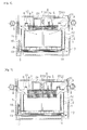
- FIGS. 1 to 17 are diagrams illustrating an air-conditioning system according to an exemplary embodiment of the present invention and the air-conditioning system according to the exemplary embodiment includes a storage chamber 1 having a space portion therein, a cooling chamber 2 including a heat medium supplying unit positioned in the storage chamber 1, having the space portion therein, and supplying a heat medium onto the space portion and including an air inflow unit configured to receive external air to cool the heat medium through the supplied air and store the cooled heat medium, and a cool wind supplying unit configured to supply air cooled to a low temperature by exchanging heat with the cooled heat medium stored in the cooling chamber 2 to a use place 3.
- a storage chamber 1 having a space portion therein
- a cooling chamber 2 including a heat medium supplying unit positioned in the storage chamber 1, having the space portion therein, and supplying a heat medium onto the space portion and including an air inflow unit configured to receive external air to cool the heat medium through the supplied air and store the cooled heat medium, and a cool wind supplying unit configured
- the heat medium is received through the heat medium supplying unit and external cool air is received through the air inflow unit to cool the heat medium, and cool and store the cooled heat medium in the cooling chamber 2 and thereafter, as necessary in the summer time, the cool wind which exchanges heat with the cooled heat medium stored in the cooling chamber 2 selectively to be cooled at the low temperature is supplied to the use place 3 through the cool wind supplying unit to cool the use place 3.
- the storage chamber 1 is formed by a basement of a multi-story building and the use place 3 is constituted by ground stories including the basement of the multi-story building.
- the environment-friendly air-conditioning system is implemented by using the basement of the multi-story building.
- the heat medium is most preferably composed of water in order to use ice (a solid state of water) having relatively high cooling power storage density, but the present invention is not limited thereto.
- the air inflow unit is formed by a blower 4 that is provided in the storage chamber 1 to blow external air to the cooling chamber 2.
- the heat medium is cooled by supplying cool air enough to cool water to the cooling chamber 2 from the outside of a building in the winter timeby using the blower 4 in the winter time to be stored in an ice state.
- the ice stored in the cooling chamber 2 is prevented from being liquefied without permission by closing the cooling chamber 2 so as to prevent the external air from flowing into the cooling chamber 2.
- the heat medium supplying unit includes a supply pipe 5 configured to supply water from the outside, a first valve 6 provided in the supply pipe 5 and configured to open and close the supply of the heat medium, a branch pipe 7 provided in the cooling chamber 2 and connected with the supply pipe 5 to receive the heat medium, and branched into multiple pipes, and an injection nozzle 8 provided in the branch pipe 7 and configured to inject the heat medium that flows into the branch pipe 7 to the cooling chamber 2.
- the heat medium is minutely injected into the cooling chamber 2 to be evenly supplied throughout an entire area on a space portion of the cooling chamber 2, the heat medium is easily condensed by increasing a contact area with the cool air supplied by the blower 4 to be stored while the heat medium is state-changed to the ice state.
- the branch pipe 7 extends radially in plural around the supply pipe 5 to evenly supply the heat medium to the entire area of the cooling chamber 2, but the present invention is not limited thereto.
- an air collecting chamber 9 configured to collect high-temperature air in the cooling chamber 2 and discharge the collected air to the outside is provided in an upper part of the space portion of the cooling chamber 2, and a discharge valve 10 configured to open and close based on pressure set according to the pressure of air to discharge the air to the outside is provided in the air collecting chamber 9.
- the cool air that exchanges heat with the heat medium in the cooling chamber 2 continuously exchanges heat with low-temperature air which flows in from the outside to increase cooling efficiency of the heat medium.
- a storage tank 11 in which the heat medium is cooled and stored is provided in the cooling chamber 2 to store the heat medium in an additional space on the cooling chamber 2, and it is preferable that an inner wall of the storage tank 11 is formed by a heat insulator 12 having elasticity to have extensibility.
- breakage and damage are prevented by actively responding to a volume which varies depending on a state change depending on condensation and liquefaction of the heat medium.
- An air chamber 13 in which cooling air is circulated is provided in a lower part of the storage tank 11, a housing chamber 14 housing a liquefied heat medium generated by liquefying the cooled heat medium is provided in a lower part of the air chamber 13, and the air chamber 13 is connected with the storage tank 11 and the housing chamber 14, and as a result, the air and the liquefied heat medium are circulated in the air chamber 13.
- a plurality of via-holes is preferably formed on a bottom surface of the storage tank 11.
- the cooled cool wind is supplied to the use place 3 via the cool wind supplying unit through the air chamber 13, and the liquefied heat medium freely falls to be housed in the housing chamber 14 via the air chamber 13.
- a blowing pipe 15 configured to supply air to the use place 3 is provided in the air chamber 13, a second valve 16 opened and closed to control the supply of air is provided in the blowing pipe 15, and an input pipe 17 configured to receive air from the outside and exchange heat with the liquefied heat medium housed in the housing chamber 14 to cool the received air at the low temperature and connected with the blowing pipe 15 to supply the air cooled at the low temperature is provided in the housing chamber 14.
- the cool wind supplying unit that supplies the cool wind to the use place 3 from the cooling chamber 2is constituted by the blowing pipe 15, the second valve 16, and the input pipe 17.
- the input pipe 17 includes a third valve 18 configured to open and close the supply of air and an air pump 19 configured to forcibly blow air.
- the cool wind that remains in the air chamber 13 is sent to the use place 3 through the blowing pipe 15 to cool the use place 3, and the cool wind is further supplied to the use place 3 by forcibly blowing the cool wind cooled through the housing chamber 14 through the input pipe 17 by using the air pump 19 due to a necessity to further supply the cool wind to the use place 3 to thereby control the temperature of air.
- an inflow pipe 20 supplying the air of the storage chamber 1 to the space portion of the cooling chamber 2 and constituted by a plurality of discharge holes is provided in the cooling chamber 2, and a fourth valve 21 opened and closed to control the supply of air is provided in the inflow pipe 20.
- a recovery pipe 22 configured to supply the low-temperature used air collected in the use place 3 is provided in the cooling chamber 2 and a fifth valve 23 opened and closed to control the supply of air is provided in the recovery pipe 22.
- the used low-temperature indoor air which has the lower temperature feature than outdoor air of the building is reused, and as a result, air-conditioning is achieved while consuming less cooling energy of the heat medium, thereby saving energy.
- the cooling chamber 2 is connected with an outlet of an ice maker 24 to receive ice made by the ice maker 24, in the air-conditioning system according to the exemplary embodiment, in order to complement the loss.
- the ice maker 24 is provided to receive power through a solar cell provided in the building of the use place 3 or receive power through a wind power generator provided in the building of the use place 3.
- the external cool air is supplied to the cooling chamber 2 in the winter time and water which is the heat medium is received through the heat medium supplying unit, and the heat medium is cooled and stored in the storage tank 11, as illustrated in FIGS. 4 to 8 .
- the heat medium which is evenly injected throughout the entire area of the storage tank 11 through the branch pipe 7 is preferably refrigerated and stored in multiple stages while forming stories.
- a process is sequentially performed, in which the air that cools the use place 3 and is recovered to the recovery pipe 22 is reinput into the cooling chamber 2 to be heat-exchanged and thereafter, reblown to the use place in a cool wind state, and as a result, the air is circulated.
- the ice is liquefied by the air supplied to the storage tank 11 to be converted into a liquid state and thereafter, freely falls and is housed in the housing chamber 14. Therefore, the liquefied water housed in the housing chamber 14 which is at the low temperature exchanges heat with air that passes through the input pipe 17 to generate the cool wind and the cool wind is forcibly blown to the use place through the air pump 19.
Landscapes
- Engineering & Computer Science (AREA)
- Mechanical Engineering (AREA)
- General Engineering & Computer Science (AREA)
- Physics & Mathematics (AREA)
- Thermal Sciences (AREA)
- Life Sciences & Earth Sciences (AREA)
- Sustainable Development (AREA)
- Chemical & Material Sciences (AREA)
- Combustion & Propulsion (AREA)
- Sustainable Energy (AREA)
- Air Conditioning Control Device (AREA)
- Central Air Conditioning (AREA)
Abstract
Description
- This application claims priority to and the benefit of Korean Patent Application No.
10-2012-0067621 - The present invention relates to air-conditioning that controls a living temperature by lowering the temperature of a room, and more particularly, to an air-conditioning system that cools and stores a heat medium (water) by using external cool air in the winter time and thereafter, supplies cool wind which is heat-exchanged with the heat medium to a place requiring the cool wind when necessary (in the summer time) to cool the room, thereby obtaining an economic gain by significantly reducing energy consumption and implement nature-friendly cooling for reducing discharge of greenhouse gas.
- In general, air-conditioning that artificially lowers the temperature of the room is performed so as to live a fresh life by controlling a human physical body temperature depending on an increase of the temperature of the room in a serious heat wave of the summer time.
- That is, a human body reaches a physical body temperature control region by perspiration when an external temperature is equal to or higher than 31°C and the human body is vulnerable to various diseases, and as a result, it is difficult to continue health and a life due to a rise of the body temperature when the external temperature is equal to or higher than 35°C.
- Therefore, the cool wind is supplied to a high-temperature room to be cooled for the health and the fresh life of the human body to achieve the health and the fresh life.
- For such cooling, a cooling apparatus (air-conditioner) is primarily used, which cools the heat medium by receiving power, lowers an air temperature to be a lower temperature by exchanging heat between the cooled heat medium and air, and thereafter, supplies the air whose temperature is lowered to a low temperature to the room to cool the room.
- However, the aforementioned conventional cooling apparatuses excessively consume additional energy (electric energy) to causes nation's power demand and supply crisis due to excessive power consumption in the summer time when cooling is rapidly saturated, degrade use efficiency of energy, and increase discharge of greenhouse gas due to production of power, thereby causing an environmental problem such as global warming.
- With an increase in energy use cost by driving the cooling apparatus, an economical problem may be caused to a user.
- The present invention has been made in an effort to provide an air-conditioning system based on a seasonal cooling power storage concept that cools and stores a heat medium (water) by using external cool air that is naturally formed in the winter time and thereafter, supplies a cool wind which is heat-exchanged with a previously stored heat medium to a place requiring the cool wind when cooling power is required to cool a room, thereby obtaining an economical gain by significantly energy consumption and implementing nature-friendly cooling for reducing discharge of greenhouse gas.
- An exemplary embodiment of the present invention provides an air-conditioning system, including: a storage chamber having a space portion therein; a cooling chamber including a heat medium supplying unit positioned in the storage chamber, having a space portion therein, and supplying a heat medium onto the space portion and including an air inflow unit configured to receive external air to cool the heat medium through the supplied air and store the cooled heat medium; and a cool wind supplying unit configured to supply air cooled at a low temperature by exchanging heat with the cooled heat medium stored in the cooling chamber to a use place.
- The storage chamber may be formed by a basement of a multi-story building.
- The use place may be constituted by ground stories including the basement of the multi-story building.
- The heat medium may be composed of water.
- The air inflow unit may be formed by a blower that is provided in the storage chamber to blow external air to the cooling chamber.
- The heat medium supplying unit may include a supply pipe configured to supply water from the outside, a first valve provided in the supply pipe to open and close the supply of the heat medium, a branch pipe provided in the cooling chamber and connected with the supply pipe to receive the heat medium, and branched into multiple pipes, and an injection nozzle provided in the branch pipe and configured to inject the heat medium that flows into the branch pipe to the cooling chamber.
- The branch pipe may extend radially in plural around the supply pipe.
- A storage tank in which the heat medium is cooled and stored may be provided in the cooling chamber.
- An air collecting chamber configured to collect high-temperature air in the cooling chamber and discharge the collected air to the outside may be provided in an upper part of the space portion of the cooling chamber, and a discharge valve configured to open and close based on pressure set according to the pressure of air to discharge the air to the outside may be provided in the air collecting chamber.
- An inner wall of the storage tank may be formed by a heat insulator having elasticity to have extensibility.
- An air chamber in which cooling air is circulated may be provided in a lower part of the storage tank.
- A housing chamber housing a liquefied heat medium generated by liquefying the cooled heat medium may be provided in a lower part of the air chamber.
- A plurality of via-holes may be formed on a bottom surface of the storage tank.
- The air chamber may be connected with the storage tank and the housing chamber, and as a result, the air and the liquefied heat medium may flow in the air chamber.
- A blowing pipe configured to supply air to the use place may be provided in the air chamber, and a second valve opened and closed to control the supply of air may be provided in the blowing pipe.
- An input pipe configured to receive air from the outside and exchange heat with the liquefied heat medium housed in the housing chamber to cool the received air at the low temperature and connected with the blowing pipe to supply the air cooled at the low temperature may be provided in the housing chamber.
- A third valve configured to open and close the supply of air may be provided in the input pipe and an air pump configured to forcibly blow air may be provided in the input pipe.
- An inflow pipe supplying the air of the storage chamber to the space portion of the cooling chamber and constituted by a plurality of discharge holes may be provided in the cooling chamber, and a fourth valve opened and closed to control the supply of air may be provided in the inflow pipe.
- A recovery pipe configured to supply the low-temperature used air collected in the use place may be provided in the cooling chamber and a fifth valve opened and closed to control the supply of air may be provided in the recovery pipe.
- The cooling chamber may be connected with an outlet of an ice maker to receive ice made by the ice maker.
- The ice maker may receive power through a solar cell provided in the building of the use place.
- The ice maker may receive power through a wind power generator provided in the building of the use place.
- According to the exemplary embodiment of the present invention, the air-conditioning system cools a heat medium (water) by using external cool air that is naturally formed in the winter time and stores the cooled heat medium in a storage of a cooling chamber and thereafter, generates a cool wind by melting the cooled heat medium stored in the storage of the cooling chamber when necessary in the summer time and cools air of a use place by using the cool wind to the use place by using a cool wind supplying means, thereby obtaining an economical gain by performing cooling without consuming additional energy and implementing environment-friendly cooling by reducing discharge of greenhouse gas through a decrease of a greenhouse gas generation cause.
-
-
FIG. 1 is a schematic cross-sectional exemplary view illustrating an air-conditioning system according to an exemplary embodiment of the present invention. -
FIG. 2 is a schematic cross-sectional exemplary view illustrating an operation of cooling a heat medium in the air-conditioning system according to the exemplary embodiment. -
FIG. 3 is a schematic cross-sectional exemplary view illustrating an operation of generating a cool wind through the heat medium and supplying the generated cool wind to a use place in the air-conditioning system according to the exemplary embodiment. -
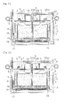
FIGS. 4 to 8 are partial schematic exemplary views sequentially illustrating an operation of cooling the heat medium in the air-conditioning system according to the exemplary embodiment. -
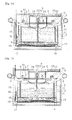
FIGS. 9 to 15 are partial schematic exemplary views sequentially illustrating an operation of generating the cool wind through the heat medium and supplying the generated cool wind in the air-conditioning system according to the exemplary embodiment. -
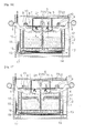
FIGS. 16 and 17 are partial schematic exemplary views illustrating complementation of the cooled heat medium lost in the air-conditioning system according to the exemplary embodiment. - Hereinafter, an air-conditioning system according to an exemplary embodiment of the present invention will be described in detail below with reference to the accompanying drawings.
- Moreover, as terms used in the present invention, general terms generally widely used at present as possible are selected, but in a specific case, terms arbitrarily selected by an applicant may be used and in this case, meanings thereof are described in detail in a description part of the present invention which is relevant, and as a result, it is apparent that the present invention is appreciated with not simple names of terms but the meanings of the terms. Further, in describing an exemplary embodiment, a description of a technical content which is well known in a technical field to which the present invention pertains and is not directly related with the present invention will be omitted. This is to more clearly transfer the spirit of the present invention without making the spirit of the present invention be opaque by omitting an unnecessary description.
-
FIGS. 1 to 17 are diagrams illustrating an air-conditioning system according to an exemplary embodiment of the present invention and the air-conditioning system according to the exemplary embodiment includes astorage chamber 1 having a space portion therein, acooling chamber 2 including a heat medium supplying unit positioned in thestorage chamber 1, having the space portion therein, and supplying a heat medium onto the space portion and including an air inflow unit configured to receive external air to cool the heat medium through the supplied air and store the cooled heat medium, and a cool wind supplying unit configured to supply air cooled to a low temperature by exchanging heat with the cooled heat medium stored in thecooling chamber 2 to ause place 3. - That is, in the winter time, the heat medium is received through the heat medium supplying unit and external cool air is received through the air inflow unit to cool the heat medium, and cool and store the cooled heat medium in the
cooling chamber 2 and thereafter, as necessary in the summer time, the cool wind which exchanges heat with the cooled heat medium stored in thecooling chamber 2 selectively to be cooled at the low temperature is supplied to theuse place 3 through the cool wind supplying unit to cool theuse place 3. - Therefore, an economic gain is obtained as a room is cooled without consuming additional energy for production of cooling power and discharge of greenhouse gas is reduced by decreasing a greenhouse gas generation cause through, thereby implementing environment-friendly air-conditioning to implement environment-friendly air-conditioning.
- In the air-conditioning system according to the exemplary embodiment, it is preferable that the
storage chamber 1 is formed by a basement of a multi-story building and theuse place 3 is constituted by ground stories including the basement of the multi-story building. - It is most preferable that the environment-friendly air-conditioning system is implemented by using the basement of the multi-story building.
- The heat medium is most preferably composed of water in order to use ice (a solid state of water) having relatively high cooling power storage density, but the present invention is not limited thereto.
- In the air-conditioning system according to the exemplary embodiment, the air inflow unit is formed by a
blower 4 that is provided in thestorage chamber 1 to blow external air to thecooling chamber 2. - That is, the heat medium is cooled by supplying cool air enough to cool water to the
cooling chamber 2 from the outside of a building in the winter timeby using theblower 4 in the winter time to be stored in an ice state. - Of course, after a cooling work of the heat medium is completed, the ice stored in the
cooling chamber 2 is prevented from being liquefied without permission by closing thecooling chamber 2 so as to prevent the external air from flowing into thecooling chamber 2. - In the air-conditioning system according to the exemplary embodiment, the heat medium supplying unit includes a
supply pipe 5 configured to supply water from the outside, afirst valve 6 provided in thesupply pipe 5 and configured to open and close the supply of the heat medium, abranch pipe 7 provided in thecooling chamber 2 and connected with thesupply pipe 5 to receive the heat medium, and branched into multiple pipes, and aninjection nozzle 8 provided in thebranch pipe 7 and configured to inject the heat medium that flows into thebranch pipe 7 to thecooling chamber 2. - As a result, air is supplied through the
supply pipe 5, and the heat medium is injected and supplied into thecooling chamber 2 from theinjection nozzle 8 via thebranch pipe 7 by opening thefirst valve 6. - That is, as the heat medium is minutely injected into the
cooling chamber 2 to be evenly supplied throughout an entire area on a space portion of thecooling chamber 2, the heat medium is easily condensed by increasing a contact area with the cool air supplied by theblower 4 to be stored while the heat medium is state-changed to the ice state. - Therefore, heat-exchange efficiency of the cool air and the heat medium is increased to rapidly cool and store the heat medium.
- As described above, it is preferable that the
branch pipe 7 extends radially in plural around thesupply pipe 5 to evenly supply the heat medium to the entire area of thecooling chamber 2, but the present invention is not limited thereto. - In the air-conditioning system according to the exemplary embodiment, an
air collecting chamber 9 configured to collect high-temperature air in thecooling chamber 2 and discharge the collected air to the outside is provided in an upper part of the space portion of thecooling chamber 2, and adischarge valve 10 configured to open and close based on pressure set according to the pressure of air to discharge the air to the outside is provided in theair collecting chamber 9. - That is, air of which the temperature is increased by receiving heat through heat-exchange with the heat medium is naturally lifted in the cooling chamber2 and the temperature-increased air is received by the
air collecting chamber 9 and discharged to the outside (storage chamber) through thedischarge valve 10. - Accordingly, the cool air that exchanges heat with the heat medium in the
cooling chamber 2 continuously exchanges heat with low-temperature air which flows in from the outside to increase cooling efficiency of the heat medium. - In the air-conditioning system according to the exemplary embodiment, a
storage tank 11 in which the heat medium is cooled and stored is provided in thecooling chamber 2 to store the heat medium in an additional space on thecooling chamber 2, and it is preferable that an inner wall of thestorage tank 11 is formed by aheat insulator 12 having elasticity to have extensibility. - That is, breakage and damage are prevented by actively responding to a volume which varies depending on a state change depending on condensation and liquefaction of the heat medium.
- An
air chamber 13 in which cooling air is circulated is provided in a lower part of thestorage tank 11, ahousing chamber 14 housing a liquefied heat medium generated by liquefying the cooled heat medium is provided in a lower part of theair chamber 13, and theair chamber 13 is connected with thestorage tank 11 and thehousing chamber 14, and as a result, the air and the liquefied heat medium are circulated in theair chamber 13. - To this end, a plurality of via-holes is preferably formed on a bottom surface of the
storage tank 11. - Therefore, as necessary in the summer timeair is input into the
cooling chamber 2 to exchange heat with the cooled heat medium stored in thestorage tank 11, the cooled cool wind is supplied to theuse place 3 via the cool wind supplying unit through theair chamber 13, and the liquefied heat medium freely falls to be housed in thehousing chamber 14 via theair chamber 13. - While the liquefied heat medium is housed in the
housing chamber 14 via theair chamber 13, the cool wind passing through theair chamber 13 is further cooled and supplied to theuse place 3. - A blowing
pipe 15 configured to supply air to theuse place 3 is provided in theair chamber 13, asecond valve 16 opened and closed to control the supply of air is provided in the blowingpipe 15, and aninput pipe 17 configured to receive air from the outside and exchange heat with the liquefied heat medium housed in thehousing chamber 14 to cool the received air at the low temperature and connected with the blowingpipe 15 to supply the air cooled at the low temperature is provided in thehousing chamber 14. - That is, the cool wind supplying unit that supplies the cool wind to the
use place 3 from the cooling chamber 2is constituted by the blowingpipe 15, thesecond valve 16, and theinput pipe 17. - The
input pipe 17 includes athird valve 18 configured to open and close the supply of air and anair pump 19 configured to forcibly blow air. - Therefore, the cool wind that remains in the
air chamber 13 is sent to theuse place 3 through the blowingpipe 15 to cool theuse place 3, and the cool wind is further supplied to theuse place 3 by forcibly blowing the cool wind cooled through thehousing chamber 14 through theinput pipe 17 by using theair pump 19 due to a necessity to further supply the cool wind to theuse place 3 to thereby control the temperature of air. - In the air-conditioning system according to the exemplary embodiment, an inflow pipe 20 supplying the air of the
storage chamber 1 to the space portion of thecooling chamber 2 and constituted by a plurality of discharge holes is provided in thecooling chamber 2, and a fourth valve 21 opened and closed to control the supply of air is provided in the inflow pipe 20. - Therefore, as air that exchanges heat with the cooled heat medium stored in the
storage tank 11, indoor air of thestorage chamber 1, which has a lower temperature feature than outdoor air of the building is used, and as a result, air-conditioning is achieved while consuming less cooling energy of the heat medium. - In the air-conditioning system according to the exemplary embodiment, a recovery pipe 22 configured to supply the low-temperature used air collected in the
use place 3 is provided in thecooling chamber 2 and a fifth valve 23 opened and closed to control the supply of air is provided in the recovery pipe 22. - That is, as the air that exchanges heat with the cooled heat medium stored in the
storage tank 11, the used low-temperature indoor air which has the lower temperature feature than outdoor air of the building is reused, and as a result, air-conditioning is achieved while consuming less cooling energy of the heat medium, thereby saving energy. - As described above, when the cooled heat medium stored in the
storage tank 11 is lost, the coolingchamber 2 is connected with an outlet of anice maker 24 to receive ice made by theice maker 24, in the air-conditioning system according to the exemplary embodiment, in order to complement the loss. - It is preferable that the
ice maker 24 is provided to receive power through a solar cell provided in the building of theuse place 3 or receive power through a wind power generator provided in the building of theuse place 3. - That is, it is most preferable to supplement the
cooling chamber 2 with the cooling power by using natural energy. - In the air-conditioning system according to the exemplary embodiment configured as above, the external cool air is supplied to the
cooling chamber 2 in the winter time and water which is the heat medium is received through the heat medium supplying unit, and the heat medium is cooled and stored in thestorage tank 11, as illustrated inFIGS. 4 to 8 . - In this case, the heat medium which is evenly injected throughout the entire area of the
storage tank 11 through thebranch pipe 7 is preferably refrigerated and stored in multiple stages while forming stories. - That is, by repeating a process of cooling water with a predetermined thickness and then stacking and cooling water with a predetermined thickness thereon, ice is cooled and stored to be stacked in multiple stages with stories.
- As illustrated in
FIGS. 9 to 15 , as necessary in the summer timewhen the air of thestorage chamber 1 is input into the upper part of thestorage tank 11 and thus exchanges heat with the ice to form the cool wind, the cool wind freely falls downward to flow into theair chamber 13 and is supplied to theuse place 3 through the blowingpipe 15 configuring the cool wind supplying unit to cool theuse place 3. - A process is sequentially performed, in which the air that cools the
use place 3 and is recovered to the recovery pipe 22 is reinput into thecooling chamber 2 to be heat-exchanged and thereafter, reblown to the use place in a cool wind state, and as a result, the air is circulated. - The ice is liquefied by the air supplied to the
storage tank 11 to be converted into a liquid state and thereafter, freely falls and is housed in thehousing chamber 14. Therefore, the liquefied water housed in thehousing chamber 14 which is at the low temperature exchanges heat with air that passes through theinput pipe 17 to generate the cool wind and the cool wind is forcibly blown to the use place through theair pump 19. - That is, when a large amount of cool wind is required, the cool wind is just supplied by driving the
air pump 19. - When the heat medium in a cooling state, which is stored in the
storage tank 11 is excessively consumed, stable air-conditioning is achieved by supplementing the cooling power by receiving ice made through theice maker 24. - Although the present invention has been described with the above examples, the present invention is not particularly limited to the examples and various modifications can be made without departing from the spirit of the present invention. Accordingly, the disclosed examples are not used to not limit the spirit of the present invention but describe the spirit and the scope of the spirit of the present invention is not limited by the examples. The scope of the present invention should be interpreted based on the following appended claims. It should be analyzed that all spirits which are within an equivalent range are included in the claims of the present invention.
Claims (23)
- An air-conditioning system based on seasonal cooling power storage, comprising:a storage chamber having a space portion therein;a cooling chamber including a heat medium supplying unit positioned in the storage chamber, having a space portion therein, and supplying a heat medium onto the space portion and including an air inflow unit configured to receive external air to cool the heat medium through the supplied air and store the cooled heat medium; anda cool wind supplying unit configured to supply air cooled at a low temperature by exchanging heat with the cooled heat medium stored in the cooling chamber to a use place.
- The air-conditioning system based on seasonal cooling power storage of claim 1, wherein the storage chamber is formed by a basement of a multi-story building.
- The air-conditioning system based on seasonal cooling power storage of claim 1, wherein the use place is constituted by ground stories including the basement of the multi-story building.
- The air-conditioning system based on seasonal cooling power storage of claim 1, wherein the heat medium is composed of water.
- The air-conditioning system based on seasonal cooling power storage of claim 1, wherein the air inflow unit is formed by a blower that is provided in the storage chamber to blow external air to the cooling chamber.
- The air-conditioning system based on seasonal cooling power storage of claim 1, wherein the heat medium supplying unit includes:a supply pipe configured to supply water from the outside;a first valve provided in the supply pipe and configured to open and close the supply of the heat medium;a branch pipe provided in the cooling chamber and connected with the supply pipe to receive the heat medium, and branched into multiple pipes; andan injection nozzle provided in the branch pipe and configured to inject the heat medium that flows into the branch pipe to the cooling chamber.
- The air-conditioning system based on seasonal cooling power storage of claim 6, wherein the branch pipe extends radially in plural around the supply pipe.
- The air-conditioning system based on seasonal cooling power storage of claim 1, wherein a storage tank in which the heat medium is cooled and stored is provided in the cooling chamber.
- The air-conditioning system based on seasonal cooling power storage of claim 1, wherein an air collecting chamber configured to collect high-temperature air in the cooling chamber and discharge the collected air to the outside is provided in an upper part of the space portion of the cooling chamber, and a discharge valve configured to open and close based on pressure set according to the pressure of air to discharge the air to the outside is provided in the air collecting chamber.
- The air-conditioning system based on seasonal cooling power storage of claim 8, wherein an inner wall of the storage tank is formed by a heat insulator having elasticity to have extensibility.
- The air-conditioning system based on seasonal cooling power storage of claim 8, wherein an air chamber in which cooling air is circulated is provided in a lower part of the storage tank.
- The air-conditioning system based on seasonal cooling power storage of claim 11, wherein a housing chamber housing a liquefied heat medium generated by liquefying the cooled heat medium is provided in a lower part of the air chamber.
- The air-conditioning system based on seasonal cooling power storage of claim 8, wherein a plurality of via-holes is formed on a bottom surface of the storage tank.
- The air-conditioning system based on seasonal cooling power storage of any one of claims 11 and 12, wherein the air chamber is connected with the storage tank and the housing chamber such that the air and the liquefied heat medium flows in the air chamber.
- The air-conditioning system based on seasonal cooling power storage of claim 11, wherein a blowing pipe configured to supply air to the use place is provided in the air chamber, and a second valve opened and closed to control the supply of air is provided in the blowing pipe.
- The air-conditioning system based on seasonal cooling power storage of any one of claims 12 and 15, wherein an input pipe configured to receive air from the outside and exchange heat with the liquefied heat medium housed in the housing chamber to cool the received air at the low temperature and connected with the blowing pipe to supply the air cooled at the low temperature is provided in the housing chamber.
- The air-conditioning system based on seasonal cooling power storage of claim 16, wherein a third valve configured to open and close the supply of air is provided in the input pipe and an air pump configured to forcibly blow air is provided in the input pipe.
- The air-conditioning system based on seasonal cooling power storage of claim 1, wherein an inflow pipe supplying the air of the storage chamber to the space portion of the cooling chamber and constituted by a plurality of discharge holes is provided in the cooling chamber, and a fourth valve opened and closed to control the supply of air is provided in the inflow pipe.
- The air-conditioning system based on seasonal cooling power storage of claim 1, wherein a recovery pipe configured to supply the low-temperature used air collected in the use place is provided in the cooling chamber and a fifth valve opened and closed to control the supply of air is provided in the recovery pipe.
- The air-conditioning system based on seasonal cooling power storage of claim 1, wherein the cooling chamber is connected with an outlet of an ice maker to receive ice made by the ice maker.
- The air-conditioning system based on seasonal cooling power storage of claim 20, wherein the ice maker receives power through a solar cell provided in the building of the use place.
- The air-conditioning system based on seasonal cooling power storage of claim 20, wherein the ice maker receives power through a wind power generator provided in the building of the use place.
- The air-conditioning system based on seasonal cooling power storage of claim 1, wherein by sequentially repeating a process of cooling water with a predetermined thickness and then stacking and cooling water with a predetermined thickness thereon in cooling of a heat medium through outdoor air, ice is cooled and stored to be effectively stacked in multiple stages with stories.
Applications Claiming Priority (2)
| Application Number | Priority Date | Filing Date | Title |
|---|---|---|---|
| KR1020120067621A KR20140003695A (en) | 2012-06-22 | 2012-06-22 | An air-conditioning system based on seasonal cooling power storage |
| PCT/KR2012/008832 WO2013191331A1 (en) | 2012-06-22 | 2012-10-26 | Cooling system using cold air on inter-seasonal basis |
Publications (3)
| Publication Number | Publication Date |
|---|---|
| EP2711644A1 true EP2711644A1 (en) | 2014-03-26 |
| EP2711644A4 EP2711644A4 (en) | 2016-02-17 |
| EP2711644B1 EP2711644B1 (en) | 2018-08-01 |
Family
ID=49768907
Family Applications (1)
| Application Number | Title | Priority Date | Filing Date |
|---|---|---|---|
| EP12873882.0A Active EP2711644B1 (en) | 2012-06-22 | 2012-10-26 | Cooling system using cold air on inter-seasonal basis |
Country Status (4)
| Country | Link |
|---|---|
| EP (1) | EP2711644B1 (en) |
| JP (1) | JP5807799B2 (en) |
| KR (1) | KR20140003695A (en) |
| WO (1) | WO2013191331A1 (en) |
Cited By (3)
| Publication number | Priority date | Publication date | Assignee | Title |
|---|---|---|---|---|
| FR3080439A1 (en) * | 2018-04-24 | 2019-10-25 | Jean Raymond | METHOD AND DEVICE FOR THERMAL CONTROL OF A BUILDING |
| WO2021167479A1 (en) * | 2020-02-20 | 2021-08-26 | Mohammed Ejaz | Cooling reduction using soil temperature |
| CN115790030A (en) * | 2023-02-13 | 2023-03-14 | 深圳市前海能源科技发展有限公司 | Cold-storage equipment and electric power peak regulation system |
Families Citing this family (2)
| Publication number | Priority date | Publication date | Assignee | Title |
|---|---|---|---|---|
| KR101649329B1 (en) * | 2016-06-23 | 2016-08-18 | 대양기전 주식회사 | Refrigerator with ice maker |
| KR102532590B1 (en) * | 2020-10-23 | 2023-05-15 | 이낙영 | Greenhouse gas treatment device |
Family Cites Families (11)
| Publication number | Priority date | Publication date | Assignee | Title |
|---|---|---|---|---|
| US1297633A (en) * | 1917-11-07 | 1919-03-18 | Charles S Ashley | Cooling and ventilating method. |
| JPH06257799A (en) * | 1993-03-01 | 1994-09-16 | Kajima Corp | Personal ice storage cooling system |
| JP2001235180A (en) * | 1999-12-12 | 2001-08-31 | Ice Shelter:Kk | Ventilation cooling method and apparatus using natural ice |
| JP2001317845A (en) * | 2000-05-02 | 2001-11-16 | Dogoshi Hitoshi | Method and apparatus for utilizing cold heat of natural ice |
| JP3611199B2 (en) * | 2001-02-05 | 2005-01-19 | 大成建設株式会社 | Thermal storage air conditioning system using natural cold air |
| JP4096587B2 (en) * | 2002-03-20 | 2008-06-04 | 株式会社大林組 | Cold storage facility |
| JP2003336869A (en) * | 2002-05-15 | 2003-11-28 | Kudo Kensetsu Kk | Snow preservation method and design method for snow preserving snow/ice storage |
| JP4146732B2 (en) * | 2003-01-14 | 2008-09-10 | 鹿島建設株式会社 | Snow and ice heat source supply system |
| JP2005042511A (en) * | 2003-07-25 | 2005-02-17 | Sunrise Square Hanbai Kk | Rc heat storage air conditioning system and its method of construction |
| JP5374133B2 (en) * | 2008-12-16 | 2013-12-25 | 株式会社土谷特殊農機具製作所 | Ice storage facility using cylindrical water tank |
| JP2011226753A (en) * | 2010-04-20 | 2011-11-10 | Kiyoshi Yanagimachi | Air conditioning facility and geothermal heat pipe |
-
2012
- 2012-06-22 KR KR1020120067621A patent/KR20140003695A/en not_active Ceased
- 2012-10-26 WO PCT/KR2012/008832 patent/WO2013191331A1/en not_active Ceased
- 2012-10-26 JP JP2014521578A patent/JP5807799B2/en not_active Expired - Fee Related
- 2012-10-26 EP EP12873882.0A patent/EP2711644B1/en active Active
Cited By (4)
| Publication number | Priority date | Publication date | Assignee | Title |
|---|---|---|---|---|
| FR3080439A1 (en) * | 2018-04-24 | 2019-10-25 | Jean Raymond | METHOD AND DEVICE FOR THERMAL CONTROL OF A BUILDING |
| EP3561402A1 (en) * | 2018-04-24 | 2019-10-30 | Jean Raymond | Method and device for thermal control of a building |
| WO2021167479A1 (en) * | 2020-02-20 | 2021-08-26 | Mohammed Ejaz | Cooling reduction using soil temperature |
| CN115790030A (en) * | 2023-02-13 | 2023-03-14 | 深圳市前海能源科技发展有限公司 | Cold-storage equipment and electric power peak regulation system |
Also Published As
| Publication number | Publication date |
|---|---|
| WO2013191331A1 (en) | 2013-12-27 |
| EP2711644B1 (en) | 2018-08-01 |
| KR20140003695A (en) | 2014-01-10 |
| JP5807799B2 (en) | 2015-11-10 |
| EP2711644A4 (en) | 2016-02-17 |
| JP2014519012A (en) | 2014-08-07 |
Similar Documents
| Publication | Publication Date | Title |
|---|---|---|
| CN103190313B (en) | Air energy soil-thermal storage heating and cooling device for fruit and vegetable plastic sheds or greenhouses in cold areas | |
| CN102589195A (en) | Heat supply and refrigeration system combining spatial energy with ground source energy | |
| EP2711644B1 (en) | Cooling system using cold air on inter-seasonal basis | |
| CN104792067B (en) | Soil source solar heat pump warmhouse booth heating system and control method | |
| CN107062472A (en) | Double cold source refrigerating systems that natural cooling unit is combined with centrifugal water chillers | |
| US20250351782A1 (en) | Energy and hydrometric control of horticultural greenhouses | |
| CN2797997Y (en) | Multi-functional integrated cabinet machine of regrigerator and air conditioner | |
| CN106482265A (en) | A kind of ground energy pipe laying constant temperature system of efficient energy-saving and emission-reducing | |
| CN203798019U (en) | Waste heat recovery device for water source heat pump | |
| CN206572676U (en) | Double cold source refrigerating systems that natural cooling unit is combined with centrifugal water chillers | |
| CN206496460U (en) | Whole year operation air-conditioning cooling device | |
| CN201852397U (en) | Improved heat-exchange device of evaporating cold and defrosting water | |
| CN204757443U (en) | Viscose degasification refrigeration cycle water cooling system | |
| CN104214869A (en) | A high-efficiency water storage device | |
| CN102759161B (en) | Solar radiation air-conditioner | |
| CN104566708A (en) | Heat pump type household air conditioning method and device as well as outdoor module of device | |
| CN210569361U (en) | Deep well water direct cooling coupling deep well water source heat pump system | |
| CN102759160B (en) | Ground source heat pump and energy storing method thereof | |
| CN107166803A (en) | A kind of hot and cold water economic benefits and social benefits exchange cycles system of edible mushroom factory | |
| CN108224623B (en) | Passive fresh air system using dry air energy and solar energy as driving energy | |
| CN213577845U (en) | An air-conditioning refrigeration system combining water-cooled seasonal cold storage and evaporative cooling | |
| CN203964463U (en) | A kind of novel high-efficiency and energy-saving condenser | |
| CN104157400B (en) | One kind has photovoltaic conversion function main transformer falling film type heat-exchanger rig and application method | |
| KR101337353B1 (en) | Heat pump system using water for irrigation of golf course reservoir | |
| CN206398898U (en) | The wine cellar air-conditioning system that solar energy is applied with geothermal energy united |
Legal Events
| Date | Code | Title | Description |
|---|---|---|---|
| PUAI | Public reference made under article 153(3) epc to a published international application that has entered the european phase |
Free format text: ORIGINAL CODE: 0009012 |
|
| 17P | Request for examination filed |
Effective date: 20131015 |
|
| AK | Designated contracting states |
Kind code of ref document: A1 Designated state(s): AL AT BE BG CH CY CZ DE DK EE ES FI FR GB GR HR HU IE IS IT LI LT LU LV MC MK MT NL NO PL PT RO RS SE SI SK SM TR |
|
| RIN1 | Information on inventor provided before grant (corrected) |
Inventor name: PARK, BYUNG SIK Inventor name: IM, YONGHOON Inventor name: CHUNG, DEAHUN |
|
| DAX | Request for extension of the european patent (deleted) | ||
| RA4 | Supplementary search report drawn up and despatched (corrected) |
Effective date: 20160120 |
|
| RIC1 | Information provided on ipc code assigned before grant |
Ipc: F24J 2/00 20140101ALI20160114BHEP Ipc: F24F 11/00 20060101ALI20160114BHEP Ipc: F28D 20/00 20060101ALI20160114BHEP Ipc: F28D 20/02 20060101ALI20160114BHEP Ipc: F24F 5/00 20060101AFI20160114BHEP Ipc: F28F 25/06 20060101ALI20160114BHEP |
|
| REG | Reference to a national code |
Ref country code: DE Ref legal event code: R079 Ref document number: 602012049284 Country of ref document: DE Free format text: PREVIOUS MAIN CLASS: F24F0005000000 Ipc: F28D0020020000 |
|
| GRAP | Despatch of communication of intention to grant a patent |
Free format text: ORIGINAL CODE: EPIDOSNIGR1 |
|
| RIC1 | Information provided on ipc code assigned before grant |
Ipc: F24F 5/00 20060101ALI20180201BHEP Ipc: F28F 25/06 20060101ALI20180201BHEP Ipc: F28D 20/00 20060101ALI20180201BHEP Ipc: F24F 11/00 20180101ALI20180201BHEP Ipc: F28D 20/02 20060101AFI20180201BHEP |
|
| INTG | Intention to grant announced |
Effective date: 20180219 |
|
| GRAS | Grant fee paid |
Free format text: ORIGINAL CODE: EPIDOSNIGR3 |
|
| GRAA | (expected) grant |
Free format text: ORIGINAL CODE: 0009210 |
|
| AK | Designated contracting states |
Kind code of ref document: B1 Designated state(s): AL AT BE BG CH CY CZ DE DK EE ES FI FR GB GR HR HU IE IS IT LI LT LU LV MC MK MT NL NO PL PT RO RS SE SI SK SM TR |
|
| REG | Reference to a national code |
Ref country code: GB Ref legal event code: FG4D |
|
| REG | Reference to a national code |
Ref country code: CH Ref legal event code: EP Ref country code: AT Ref legal event code: REF Ref document number: 1024803 Country of ref document: AT Kind code of ref document: T Effective date: 20180815 |
|
| REG | Reference to a national code |
Ref country code: IE Ref legal event code: FG4D |
|
| REG | Reference to a national code |
Ref country code: DE Ref legal event code: R096 Ref document number: 602012049284 Country of ref document: DE |
|
| REG | Reference to a national code |
Ref country code: SE Ref legal event code: TRGR |
|
| REG | Reference to a national code |
Ref country code: NL Ref legal event code: MP Effective date: 20180801 |
|
| REG | Reference to a national code |
Ref country code: LT Ref legal event code: MG4D |
|
| REG | Reference to a national code |
Ref country code: AT Ref legal event code: MK05 Ref document number: 1024803 Country of ref document: AT Kind code of ref document: T Effective date: 20180801 |
|
| PG25 | Lapsed in a contracting state [announced via postgrant information from national office to epo] |
Ref country code: LT Free format text: LAPSE BECAUSE OF FAILURE TO SUBMIT A TRANSLATION OF THE DESCRIPTION OR TO PAY THE FEE WITHIN THE PRESCRIBED TIME-LIMIT Effective date: 20180801 Ref country code: PL Free format text: LAPSE BECAUSE OF FAILURE TO SUBMIT A TRANSLATION OF THE DESCRIPTION OR TO PAY THE FEE WITHIN THE PRESCRIBED TIME-LIMIT Effective date: 20180801 Ref country code: IS Free format text: LAPSE BECAUSE OF FAILURE TO SUBMIT A TRANSLATION OF THE DESCRIPTION OR TO PAY THE FEE WITHIN THE PRESCRIBED TIME-LIMIT Effective date: 20181201 Ref country code: RS Free format text: LAPSE BECAUSE OF FAILURE TO SUBMIT A TRANSLATION OF THE DESCRIPTION OR TO PAY THE FEE WITHIN THE PRESCRIBED TIME-LIMIT Effective date: 20180801 Ref country code: GR Free format text: LAPSE BECAUSE OF FAILURE TO SUBMIT A TRANSLATION OF THE DESCRIPTION OR TO PAY THE FEE WITHIN THE PRESCRIBED TIME-LIMIT Effective date: 20181102 Ref country code: FI Free format text: LAPSE BECAUSE OF FAILURE TO SUBMIT A TRANSLATION OF THE DESCRIPTION OR TO PAY THE FEE WITHIN THE PRESCRIBED TIME-LIMIT Effective date: 20180801 Ref country code: NO Free format text: LAPSE BECAUSE OF FAILURE TO SUBMIT A TRANSLATION OF THE DESCRIPTION OR TO PAY THE FEE WITHIN THE PRESCRIBED TIME-LIMIT Effective date: 20181101 Ref country code: BG Free format text: LAPSE BECAUSE OF FAILURE TO SUBMIT A TRANSLATION OF THE DESCRIPTION OR TO PAY THE FEE WITHIN THE PRESCRIBED TIME-LIMIT Effective date: 20181101 Ref country code: AT Free format text: LAPSE BECAUSE OF FAILURE TO SUBMIT A TRANSLATION OF THE DESCRIPTION OR TO PAY THE FEE WITHIN THE PRESCRIBED TIME-LIMIT Effective date: 20180801 Ref country code: NL Free format text: LAPSE BECAUSE OF FAILURE TO SUBMIT A TRANSLATION OF THE DESCRIPTION OR TO PAY THE FEE WITHIN THE PRESCRIBED TIME-LIMIT Effective date: 20180801 |
|
| PG25 | Lapsed in a contracting state [announced via postgrant information from national office to epo] |
Ref country code: HR Free format text: LAPSE BECAUSE OF FAILURE TO SUBMIT A TRANSLATION OF THE DESCRIPTION OR TO PAY THE FEE WITHIN THE PRESCRIBED TIME-LIMIT Effective date: 20180801 Ref country code: LV Free format text: LAPSE BECAUSE OF FAILURE TO SUBMIT A TRANSLATION OF THE DESCRIPTION OR TO PAY THE FEE WITHIN THE PRESCRIBED TIME-LIMIT Effective date: 20180801 Ref country code: AL Free format text: LAPSE BECAUSE OF FAILURE TO SUBMIT A TRANSLATION OF THE DESCRIPTION OR TO PAY THE FEE WITHIN THE PRESCRIBED TIME-LIMIT Effective date: 20180801 |
|
| PG25 | Lapsed in a contracting state [announced via postgrant information from national office to epo] |
Ref country code: CZ Free format text: LAPSE BECAUSE OF FAILURE TO SUBMIT A TRANSLATION OF THE DESCRIPTION OR TO PAY THE FEE WITHIN THE PRESCRIBED TIME-LIMIT Effective date: 20180801 Ref country code: IT Free format text: LAPSE BECAUSE OF FAILURE TO SUBMIT A TRANSLATION OF THE DESCRIPTION OR TO PAY THE FEE WITHIN THE PRESCRIBED TIME-LIMIT Effective date: 20180801 Ref country code: ES Free format text: LAPSE BECAUSE OF FAILURE TO SUBMIT A TRANSLATION OF THE DESCRIPTION OR TO PAY THE FEE WITHIN THE PRESCRIBED TIME-LIMIT Effective date: 20180801 Ref country code: RO Free format text: LAPSE BECAUSE OF FAILURE TO SUBMIT A TRANSLATION OF THE DESCRIPTION OR TO PAY THE FEE WITHIN THE PRESCRIBED TIME-LIMIT Effective date: 20180801 Ref country code: EE Free format text: LAPSE BECAUSE OF FAILURE TO SUBMIT A TRANSLATION OF THE DESCRIPTION OR TO PAY THE FEE WITHIN THE PRESCRIBED TIME-LIMIT Effective date: 20180801 |
|
| REG | Reference to a national code |
Ref country code: DE Ref legal event code: R097 Ref document number: 602012049284 Country of ref document: DE |
|
| PG25 | Lapsed in a contracting state [announced via postgrant information from national office to epo] |
Ref country code: DK Free format text: LAPSE BECAUSE OF FAILURE TO SUBMIT A TRANSLATION OF THE DESCRIPTION OR TO PAY THE FEE WITHIN THE PRESCRIBED TIME-LIMIT Effective date: 20180801 Ref country code: SK Free format text: LAPSE BECAUSE OF FAILURE TO SUBMIT A TRANSLATION OF THE DESCRIPTION OR TO PAY THE FEE WITHIN THE PRESCRIBED TIME-LIMIT Effective date: 20180801 Ref country code: SM Free format text: LAPSE BECAUSE OF FAILURE TO SUBMIT A TRANSLATION OF THE DESCRIPTION OR TO PAY THE FEE WITHIN THE PRESCRIBED TIME-LIMIT Effective date: 20180801 |
|
| REG | Reference to a national code |
Ref country code: CH Ref legal event code: PL |
|
| PLBE | No opposition filed within time limit |
Free format text: ORIGINAL CODE: 0009261 |
|
| STAA | Information on the status of an ep patent application or granted ep patent |
Free format text: STATUS: NO OPPOSITION FILED WITHIN TIME LIMIT |
|
| REG | Reference to a national code |
Ref country code: BE Ref legal event code: MM Effective date: 20181031 |
|
| PG25 | Lapsed in a contracting state [announced via postgrant information from national office to epo] |
Ref country code: MC Free format text: LAPSE BECAUSE OF FAILURE TO SUBMIT A TRANSLATION OF THE DESCRIPTION OR TO PAY THE FEE WITHIN THE PRESCRIBED TIME-LIMIT Effective date: 20180801 Ref country code: LU Free format text: LAPSE BECAUSE OF NON-PAYMENT OF DUE FEES Effective date: 20181026 |
|
| 26N | No opposition filed |
Effective date: 20190503 |
|
| GBPC | Gb: european patent ceased through non-payment of renewal fee |
Effective date: 20181101 |
|
| REG | Reference to a national code |
Ref country code: IE Ref legal event code: MM4A |
|
| PG25 | Lapsed in a contracting state [announced via postgrant information from national office to epo] |
Ref country code: BE Free format text: LAPSE BECAUSE OF NON-PAYMENT OF DUE FEES Effective date: 20181031 Ref country code: SI Free format text: LAPSE BECAUSE OF FAILURE TO SUBMIT A TRANSLATION OF THE DESCRIPTION OR TO PAY THE FEE WITHIN THE PRESCRIBED TIME-LIMIT Effective date: 20180801 Ref country code: CH Free format text: LAPSE BECAUSE OF NON-PAYMENT OF DUE FEES Effective date: 20181031 Ref country code: FR Free format text: LAPSE BECAUSE OF NON-PAYMENT OF DUE FEES Effective date: 20181031 Ref country code: LI Free format text: LAPSE BECAUSE OF NON-PAYMENT OF DUE FEES Effective date: 20181031 |
|
| PG25 | Lapsed in a contracting state [announced via postgrant information from national office to epo] |
Ref country code: IE Free format text: LAPSE BECAUSE OF NON-PAYMENT OF DUE FEES Effective date: 20181026 |
|
| PG25 | Lapsed in a contracting state [announced via postgrant information from national office to epo] |
Ref country code: GB Free format text: LAPSE BECAUSE OF NON-PAYMENT OF DUE FEES Effective date: 20181101 |
|
| PG25 | Lapsed in a contracting state [announced via postgrant information from national office to epo] |
Ref country code: MT Free format text: LAPSE BECAUSE OF NON-PAYMENT OF DUE FEES Effective date: 20181026 |
|
| PG25 | Lapsed in a contracting state [announced via postgrant information from national office to epo] |
Ref country code: TR Free format text: LAPSE BECAUSE OF FAILURE TO SUBMIT A TRANSLATION OF THE DESCRIPTION OR TO PAY THE FEE WITHIN THE PRESCRIBED TIME-LIMIT Effective date: 20180801 |
|
| PG25 | Lapsed in a contracting state [announced via postgrant information from national office to epo] |
Ref country code: PT Free format text: LAPSE BECAUSE OF FAILURE TO SUBMIT A TRANSLATION OF THE DESCRIPTION OR TO PAY THE FEE WITHIN THE PRESCRIBED TIME-LIMIT Effective date: 20180801 |
|
| PG25 | Lapsed in a contracting state [announced via postgrant information from national office to epo] |
Ref country code: HU Free format text: LAPSE BECAUSE OF FAILURE TO SUBMIT A TRANSLATION OF THE DESCRIPTION OR TO PAY THE FEE WITHIN THE PRESCRIBED TIME-LIMIT; INVALID AB INITIO Effective date: 20121026 Ref country code: MK Free format text: LAPSE BECAUSE OF NON-PAYMENT OF DUE FEES Effective date: 20180801 Ref country code: CY Free format text: LAPSE BECAUSE OF FAILURE TO SUBMIT A TRANSLATION OF THE DESCRIPTION OR TO PAY THE FEE WITHIN THE PRESCRIBED TIME-LIMIT Effective date: 20180801 |
|
| PGFP | Annual fee paid to national office [announced via postgrant information from national office to epo] |
Ref country code: SE Payment date: 20250910 Year of fee payment: 14 |
|
| PGFP | Annual fee paid to national office [announced via postgrant information from national office to epo] |
Ref country code: DE Payment date: 20250902 Year of fee payment: 14 |