EP2711590A1 - Drive gear - Google Patents
Drive gear Download PDFInfo
- Publication number
- EP2711590A1 EP2711590A1 EP13180313.2A EP13180313A EP2711590A1 EP 2711590 A1 EP2711590 A1 EP 2711590A1 EP 13180313 A EP13180313 A EP 13180313A EP 2711590 A1 EP2711590 A1 EP 2711590A1
- Authority
- EP
- European Patent Office
- Prior art keywords
- gear
- drive gear
- tooth
- grooves
- reel
- Prior art date
- Legal status (The legal status is an assumption and is not a legal conclusion. Google has not performed a legal analysis and makes no representation as to the accuracy of the status listed.)
- Granted
Links
Images




Classifications
-
- A—HUMAN NECESSITIES
- A01—AGRICULTURE; FORESTRY; ANIMAL HUSBANDRY; HUNTING; TRAPPING; FISHING
- A01K—ANIMAL HUSBANDRY; AVICULTURE; APICULTURE; PISCICULTURE; FISHING; REARING OR BREEDING ANIMALS, NOT OTHERWISE PROVIDED FOR; NEW BREEDS OF ANIMALS
- A01K89/00—Reels
- A01K89/015—Reels with a rotary drum, i.e. with a rotating spool
-
- A—HUMAN NECESSITIES
- A01—AGRICULTURE; FORESTRY; ANIMAL HUSBANDRY; HUNTING; TRAPPING; FISHING
- A01K—ANIMAL HUSBANDRY; AVICULTURE; APICULTURE; PISCICULTURE; FISHING; REARING OR BREEDING ANIMALS, NOT OTHERWISE PROVIDED FOR; NEW BREEDS OF ANIMALS
- A01K89/00—Reels
-
- A—HUMAN NECESSITIES
- A01—AGRICULTURE; FORESTRY; ANIMAL HUSBANDRY; HUNTING; TRAPPING; FISHING
- A01K—ANIMAL HUSBANDRY; AVICULTURE; APICULTURE; PISCICULTURE; FISHING; REARING OR BREEDING ANIMALS, NOT OTHERWISE PROVIDED FOR; NEW BREEDS OF ANIMALS
- A01K89/00—Reels
- A01K89/01—Reels with pick-up, i.e. with the guiding member rotating and the spool not rotating during normal retrieval of the line
-
- A—HUMAN NECESSITIES
- A01—AGRICULTURE; FORESTRY; ANIMAL HUSBANDRY; HUNTING; TRAPPING; FISHING
- A01K—ANIMAL HUSBANDRY; AVICULTURE; APICULTURE; PISCICULTURE; FISHING; REARING OR BREEDING ANIMALS, NOT OTHERWISE PROVIDED FOR; NEW BREEDS OF ANIMALS
- A01K89/00—Reels
- A01K89/01—Reels with pick-up, i.e. with the guiding member rotating and the spool not rotating during normal retrieval of the line
- A01K89/0114—Reciprocating mechanisms
-
- A—HUMAN NECESSITIES
- A01—AGRICULTURE; FORESTRY; ANIMAL HUSBANDRY; HUNTING; TRAPPING; FISHING
- A01K—ANIMAL HUSBANDRY; AVICULTURE; APICULTURE; PISCICULTURE; FISHING; REARING OR BREEDING ANIMALS, NOT OTHERWISE PROVIDED FOR; NEW BREEDS OF ANIMALS
- A01K89/00—Reels
- A01K89/015—Reels with a rotary drum, i.e. with a rotating spool
- A01K89/0183—Drive mechanism details
- A01K89/0186—Drive mechanism details with disengageable positive drive components, e.g. a clutch
-
- F—MECHANICAL ENGINEERING; LIGHTING; HEATING; WEAPONS; BLASTING
- F16—ENGINEERING ELEMENTS AND UNITS; GENERAL MEASURES FOR PRODUCING AND MAINTAINING EFFECTIVE FUNCTIONING OF MACHINES OR INSTALLATIONS; THERMAL INSULATION IN GENERAL
- F16H—GEARING
- F16H55/00—Elements with teeth or friction surfaces for conveying motion; Worms, pulleys or sheaves for gearing mechanisms
- F16H55/02—Toothed members; Worms
- F16H55/08—Profiling
Definitions
- the present invention relates to a drive gear, particularly to a drive gear to be used for a fishing reel.
- a drive gear is used for a fishing reel in order to transmit handle rotation.
- a drive gear with helical teeth is used for a dual-bearing reel in order to transmit handle rotation to a spool.
- a drive gear with face gear teeth is used for a spinning reel in order to transmit handle rotation to a rotor.
- a drive gear is necessary to enhance rotational feeling.
- the drive gear is necessary to enable the handle to be smoothly rotated without inconstant rotation as much as possible.
- a type of drive gear has been known that the number of gear teeth is increased for enhancing rotational feeling as described in Japan Laid-open Patent Application Publication No. JP-A-2012-120444 .
- frequency at which gear teeth mesh per rotation of the drive gear is increased.
- gear mesh frequency is increased.
- rotational feeling is enhanced even when amplitude is the same.
- a drive gear is increased in its diameter.
- a reel is increased in its size.
- a well-known drive gear employs micro module gear teeth with a module of 0.35 for preventing increase in its size.
- each gear tooth is reduced in its size and chances are that the drive gear is degraded in its strength unless being appropriately designed.
- a fishing reel drive gear is used for a fishing reel.
- the fishing reel drive gear is arranged to be meshed with a pinion gear.
- the fishing reel drive gear includes a gear tooth portion and a disc portion.
- the gear tooth portion has first and second gear teeth.
- the first gear tooth includes a first tooth surface.
- the second gear tooth includes a second tooth surface.
- the first tooth surface includes a first groove thereon.
- the second tooth surface includes a second groove thereon.
- the first and second grooves intersect with a mesh directional.
- the disc portion has an outer peripheral surface and a radially outer portion of a lateral face.
- the gear tooth portion is configured on the outer peripheral surface or the radially outer portion.
- the fishing reel drive gear is arranged to be meshed with the pinion gear in a direction of the mesh directional path.
- the virtual mesh frequency can be herein increased by forming the groove/grooves intersecting with the mesh directional path on the tooth surface of each gear tooth of the drive gear. Therefore, the rotational feeling of the drive gear can be enhanced without increase in diameter of the drive gear and without degradation in strength of the drive gear.
- the groove/grooves may be extended along a simultaneous mesh contact line.
- a gear to be meshed with the drive gear more reliably and easily gets across the groove/grooves due to the structure that the groove/grooves are extended along a simultaneous mesh contact line.
- the grooves may be a plurality of grooves disposed on the tooth surface at an interval or intervals in a direction of the mesh directional path.
- virtual mesh frequency is increased by a multiple of a value obtained by adding 1 to the number of grooves due to the structure that the plural grooves are disposed at an interval or intervals in the direction of the mesh directional path. Therefore, rotational feeling can be further enhanced.
- the grooves may be seven to fifteen grooves formed on the tooth surface.
- the frequency of vibrations felt by an angler exceeds 200 Hz. Therefore, rotational feeling can be further enhanced.
- the gear teeth may include face gear teeth formed on the radially outer portion of the lateral face of the disc portion. In this case, it is possible to enhance the rotational feeling of a face gear with face gear teeth as a drive gear for a spinning reel.
- the groove/grooves may be curvedly formed on the tooth surface.
- the groove/grooves are curved, and thereby, can be formed along the simultaneous mesh contact line of a pinion gear with helical teeth to be meshed with face gear teeth.
- the gear teeth may include any of spur teeth, helical teeth and double helical teeth formed on the outer peripheral surface of the disc portion. In this case, it is possible to enhance the rotational feeling of a cylindrical gear with spur teeth, helical teeth or double helical teeth as a drive gear for a dual-bearing reel.
- FIG. 1 is a cross-sectional side view of a spinning reel employing a first exemplary embodiment of the present invention
- FIG. 2 is a cross-sectional rear view of the spinning reel of FIG. 1 taken along a line II-II;
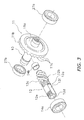
- FIG. 3 is an exploded perspective view of a rotor drive mechanism
- FIG. 4 is a plan view of the rotor drive mechanism
- FIG. 5 is a schematic view of a face gear part of a drive gear
- FIG. 6 is a plan view of a dual bearing reel employing a second exemplary embodiment of the present invention.
- FIG. 7 is a cross-sectional plan view of the dual bearing reel according to the second exemplary embodiment.
- FIG. 8 is an exploded perspective view of a gear mechanism
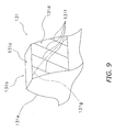
- FIG. 9 is a schematic view of a gear tooth portion with helical teeth in the drive gear.
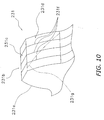
- FIG. 10 is a diagram of a drive gear according to another exemplary embodiment and corresponds to FIG. 9 .
- a spinning reel 100 (exemplary fishing reel) employing a first exemplary embodiment of the present invention includes a handle 1, a reel unit 2, a rotor 3, and a spool 4.
- the reel unit 2 supports the handle 1 in a rotatable state.
- the rotor 3 is rotatably supported at the front of the reel unit 2.
- the spool 4 is configured to wind a fishing line onto the outer peripheral surface thereof.
- the spool 4 is disposed at the front of the rotor 3 while being movable back and forth. It should be noted that the handle 1 is attachable to either of the right side and the left side of the reel unit 2.
- the handle 1 includes a handle shaft 1a, a handle arm 1b, and a handle knob 1c.
- the handle arm 1b extends from the handle shaft 1a in the radial direction of the handle shaft 1a.
- the handle knob 1c is rotatably mounted to the tip of the handle arm 1b.
- the reel unit 2 includes a reel body 2a and a lid member 2b (see FIG. 2 ).
- the reel body 2a has a laterally opened accommodation space in the inside thereof.
- the lid member 2b is detachably attached to the reel body 2a in order to close the opening of the accommodation space of the reel body 2a.
- the reel unit 2 includes a reel unit guard 26 for covering the rear part of the reel body 2a and that of the lid member 2b.
- the reel body 2a is made of, for instance, light metal alloy such as magnesium alloy or aluminum alloy. Further, the reel body 2a has a fishing rod attachment leg 2c integrally formed on the top thereof. The fishing rod attachment leg 2c is formed in a T-shape while the top thereof extends back and forth. As illustrated in FIG. 1 , the reel body 2a accommodates a rotor drive mechanism 5 and an oscillation mechanism 6 in the accommodation space.
- the rotor drive mechanism 5 is configured to rotate the rotor 3 in conjunction with rotation of the handle 1 in order to transmit rotation of the handle 1 to the rotor 3.
- the rotor drive mechanism 5 includes a drive gear 11 and a pinion gear 12.
- the drive gear 11 is configured to be rotated with a drive shaft 10 to which the handle shaft 1a of the handle 1 is coupled in a unitarily rotatable state.
- the pinion gear 12 is meshed with the drive gear 11.
- the drive gear 11 is formed integrally with the drive shaft 10 in the present exemplary embodiment.
- the drive gear 11 can be alternatively formed separately from the drive shaft 10.
- the drive shaft 10 is screwed and coupled onto the handle shaft 1a in a unitarily rotatable state in the present exemplary embodiment.
- the drive shaft 10 can be alternatively coupled onto the handle shaft 1a in a unitarily rotatable state while a non-circular cross-sectional part of the drive shaft 10 is engaged with that of the handle shaft 1a.
- the drive shaft 10 is rotatably attached to the reel unit 2 through bearings 27a and 27b.
- the bearing 27a is attached to the lid member 2b, whereas the bearing 27b is attached to the reel body 2a.
- the drive shaft 10 has a left female threaded portion 10a and a right female threaded portion 10b on the inner peripheral surfaces of the both ends thereof. Either of the left female threaded portion 10a and the right female threaded portion 10b is allowed to be screwed onto the handle shaft 1a.
- the left female threaded portion 10a which is disposed closer to the drive gear 11, is a left handed screw
- the right female threaded portion 10b which is disposed away from the drive gear 11, is a right handed screw. Therefore, as the handle shaft 1a, two types of handle shafts are prepared to be used for the left handled screw and the right handled screw.
- the drive gear 11 is of a face gear type.
- the drive gear 11 has a disc portion 11a and a gear tooth portion 11b.
- the disc portion 11a is integrally formed with the drive shaft 10.
- the gear tooth portion 11b is formed on the radially outer portion of one of the faces of the disc portion 11a.
- the gear tooth portion 11b has a plurality of face gear teeth 11c.
- the face gear teeth 11c are formed on the radially outer portion of the aforementioned face of the disc portion 11a while being circumferentially aligned at predetermined intervals.
- the drive gear 11, together with the drive shaft 10, is formed by forging of aluminum alloy, for instance. As illustrated in FIG.
- each face gear tooth 11c has a first tooth surface 11d and a second tooth surface 11e.
- the first tooth surface 11d is configured to be meshed with the pinion gear 12 when the handle 1 is rotated in a fishing-line winding direction.
- the second tooth surface 11e is configured to be meshed with the pinion gear 12 when the handle 1 is rotated in a fishing-line releasing direction.
- the first tooth surface 11d is formed as a concave surface of which a center part in the tooth trace direction is recessed.
- the second tooth surface 11e is formed as a convex surface of which a center part in the tooth trace direction protrudes.
- At least the first tooth surface 11d has at least one groove 11f formed along a direction perpendicular to a mesh directional path 11g, specifically, along a simultaneous mesh contact line 11h.
- the simultaneous mesh contact line 11h refers to a portion where the tooth tip of the pinion gear 12 linearly contacts the first tooth surface 11d of the face gear tooth 11c when the substantially entire length of the tooth width of the tooth tip of the pinion gear 12 simultaneously contacts the first tooth surface 11d of the drive gear 11.
- the simultaneous mesh contact line 11h is a line which has a shape similar to the groove 11f.
- the number of grooves 11f can be one.
- the number of grooves 11f is plural, it is preferable to form seven to fifteen grooves 11f. Accordingly, apparent mesh frequency is multiplied by eight to sixteen times, and rotational feeling can be thereby enhanced.
- a plurality of (e.g., 13) grooves 11f are formed at predetermined intervals in the direction of the mesh directional path 11g indicating the shift direction of the simultaneous mesh contact line.
- each groove 11f has a groove width in a range of 25 ⁇ m to 100 ⁇ m and has a depth in a range of 10 ⁇ m to 50 ⁇ m. It should be noted that in forming the drive gear 11 by die forming, the grooves 11f are formed with a die.
- the specification of the drive gear 11 is set as follows: a teeth number of 31; an outer diameter of 25.9 mm; an inner diameter of 21.4 mm; and a reference offset of 6.5 mm.
- the pinion gear 12 has a gear body 12a and a gear portion 12b.
- the gear body 12a has a tubular shape.
- the gear portion 12b has helical teeth 12c formed on the outer peripheral surface of the rear part of the gear body 12a.
- the gear body 12a is attached to the reel body 2a while being rotatable about an axis (i.e., a spool shaft 15) being different from the handle shaft 1a.
- the gear body 12a is rotatably supported by the reel body 2a through a front bearing 14a and a rear bearing 14b.
- the front bearing 14a is herein disposed forward of the gear portion 12b, whereas the rear bearing 14b is disposed rearward of the gear portion 12b.
- the gear body 12a has a through hole 12d in the center thereof for allowing the spool shaft 15 to penetrate therethrough.
- the gear body 12a has a male threaded portion 12e on the outer peripheral surface of the front end thereof.
- a nut 13 is screwed onto the male threaded portion 12e for fixing the rotor 3.
- the gear body 12a further has a pair of anti-rotation planes 12f on the outer peripheral surface of the front part thereof.
- the anti-rotation planes 12f are parallel planes used for coupling the rotor 3 onto the pinion gear 12 in a unitarily rotatable state.
- the drive gear 11 and the pinion gear 12 are designed to be meshed at a reference mesh height.
- the specification of the pinion gear 12 is set as follows: a module of 0.65 mm; a pressure angle of 20; a teeth number of 6; an addendum modification coefficient of +0.5; and a torsion angle of 55 degrees.
- the oscillation mechanism 6 is the one configured to move back and forth the spool shaft 15 coupled to the center part of the spool 4 through a drag mechanism 60 for moving the spool 4 in the same direction as the spool shaft 15.
- the oscillation mechanism 6 includes a traverse cam shaft 21, a slider 22 and an intermediate gear 23.
- the traverse cam shaft 21 is disposed below and in parallel to the spool shaft 15.
- the slider 22 is guided by the reel body 2a while being movable back and forth along the traverse cam shaft 21.
- the intermediate gear 23 is fixed to the tip of the traverse cam shaft 21.
- the rear end of the spool shaft 15 is fixed to the slider 22 in a non-rotatable state.
- the intermediate gear 23 is meshed with the pinion gear 12.
- the rotor 3 is made of, for instance, light metal alloy such as magnesium alloy or aluminum alloy. As illustrated in FIG. 1 , the rotor 3 is coupled to the pinion gear 12 in a non-rotatable state. However, the rotor 3 is rotatable with respect to the reel unit 2.
- the rotor 3 includes a tubular portion 30, a first rotor arm 31, and a second rotor arm 32.
- the tubular portion 30 is coupled to the pinion gear 12 in a unitarily rotatable state.
- the first and second rotor arms 31 and 32 are connected to the rear part of the tubular portion 30 while being opposed to each other. Each of the first and second rotor arms 31 and 32 forwardly extends at an interval from the tubular portion 30.
- the tubular portion 30 has a disc-shaped wall portion 30d on the inner peripheral side of the front part thereof.
- the wall portion 30d has an annular boss 30e in the center part thereof.
- the boss 30e is coupled to the pinion gear 12 in a unitarily rotatable state.
- the front part of the pinion gear 12 penetrates through the inner periphery of the boss 30e, while the anti-rotation planes 12f formed on the front part of the pinion gear 12 are fitted to the inner peripheral surface of the boss 30e in a unitarily rotatable state.
- the nut 13 is screwed onto the male threaded portion 12e of the pinion gear 12.
- the rotor 3 is thereby fixed to the pinion gear 12.
- a bail arm 44 is attached to the outer peripheral side of the tip of the first rotor arm 31 for leading the fishing line to the spool 4, while being pivotable between a fishing-line releasing position and a fishing-line winding position.
- the rotor 3 accommodates an anti-reverse mechanism 50 in the inside of the tubular portion 30 thereof.
- the anti-reverse mechanism 50 is configured to prevent or allow reverse rotation of the rotor 3.
- the anti-reverse mechanism 50 includes a one-way clutch 51 and a switching lever 52.
- the one-way clutch 51 is of a roller-type one-way clutch that the inner race thereof is allowed to freely rotate.
- the switching lever 52 is configured to switch the one-way clutch 51 between an activated state (i.e., an anti-reverse rotational state) and a deactivated state (i.e., a reverse rotational state).
- the switching lever 52 is pivotably attached to the reel body 2a.
- a cam (not illustrated in the figures) is disposed on the tip of the switching lever 52. When the switching lever 52 is pivoted, the cam switches the one-way clutch 51 between the activated state and the deactivated state.
- the spool 4 is attached onto the tip of the spool shaft 15 through the drag mechanism 60, while being disposed between the first and second rotor arms 31 and 32 of the rotor 3.
- the spool 4 has a bobbin trunk 4a, a skirt 4b, and a flange 4c.
- the bobbin trunk 4a is a portion for winding the fishing line about the outer periphery thereof.
- the skirt 4b is a tubular portion extending rearwards from the bobbin trunk 4a.
- the skirt 4b is herein integrally formed with the bobbin trunk 4a.
- the flange 4c is a large diameter portion disposed on the front end of the bobbin trunk 4a.
- the drag mechanism 60 is the one configured to brake rotation of the spool 4.
- the drag mechanism 60 includes a drag regulation knob 61 and a brake part 62.
- the drag regulation knob 61 is screwed onto the tip of the spool shaft 15.
- the brake part 62 is configured to brake the spool 4 when being pressed by the drag regulation knob 61.
- the drive gear 11 when an angler rotates the handle 1 in the fishing-line winding direction while the bail arm 44 is set to be in a fishing-line guide position after casting, the drive gear 11 is rotated in conjunction with rotation of the handle 1, and further, the pinion gear 12 meshed with the drive gear 11 is rotated. The rotor 3 is thereby rotated in the fishing-line winding direction, and the released fishing line is wound about the spool 4. At this time, the teeth of the pinion gear 12 make contact at their tips with the grooves 11f formed along the simultaneous mesh contact line. Therefore, in conjunction with rotation of the pinion gear 12, the drive gear 11 vibrates at a mesh frequency of (N + 1) times as much as the mesh frequency where no groove is formed.
- the value (N +1) is herein obtained by adding 1 to the number N of the grooves 11f. In other words, apparent mesh frequency is multiplied by (N+1) times. Accordingly, an angular comes to recognize that the rotational feeling has been enhanced.
- the grooves 11f are formed on the drive gear 11, and the apparent mesh frequency is thereby increased. Therefore, the rotational feeling of the drive gear 11 can be enhanced. In other words, the rotational feeling of the drive gear 11 can be enhanced without causing increase in diameter of the drive gear 11 and without causing degradation in strength of the drive gear 11.
- the present invention has been explained by exemplifying the drive gear 11 of a face gear type in the spinning reel 100 as an exemplary fishing reel.
- the present invention will be explained by exemplifying a drive gear 131 of a dual-bearing reel 200 as another exemplary fishing reel.
- the dual-bearing reel 200 employing the second exemplary embodiment of the present invention is a small-type low-profile bait-casting reel.
- the dual-bearing reel 200 includes a reel unit 101, a handle 102 for spool rotation and a star drag 103 for drag regulation.
- the handle 102 is disposed laterally to the reel unit 101.
- the star drag 103 is disposed on the reel unit 101 side of the handle 102.
- the reel unit 101 includes a frame 105, a first side cover 106a, and a second side cover 106b.
- the first and second side covers 106a and 106b are attached to the both lateral sides of the frame 105.
- the reel unit 101 further includes a front cover 107 and a thumb rest 108.
- the front cover 107 covers the front side of the reel unit 101, whereas the thumb rest 108 covers the top side of the reel unit 101.
- the reel unit 101 yet further includes a shaft support part 109 to be screwed to the first side cover 106a.
- a spool 112 is rotatably and detachably mounted inside the reel unit 101 for winding a fishing line.
- the frame 105 includes a pair of a first side plate 105a and a second side plate 105b and a plurality of coupling portions (not illustrated in the figures).
- the first and second side plates 105a and 105b are disposed in opposition to each other at a predetermined interval.
- the coupling portions couple the first side plate 105a and the second side plate 105b.
- the first side plate 105a has a first opening 105c for allowing the spool 112 to pass therethrough.
- the first side cover 106a is supported by the rear part of the first side plate 105a and that of the second side plate 105b while being rotatable and axially movable.
- the first side cover 106a can be opened and closed.
- the front cover 107 and the thumb rest 108 are screwed to the frame 105.
- the shaft support part 109 is a closed-end tubular member.
- the shaft support part 109 supports an end of a spool shaft 116.
- the second side cover 106b is screwed to the second side plate 105b.
- the second side cover 106b has a first boss 106c and a second boss 106d.
- the first boss 106c is provided for supporting a drive shaft 130 (to be described) to which the handle 102 is coupled.
- the second boss 106d is provided for supporting the spool shaft 116 to which the spool 112 is fixed.
- the spool 112, a level winding mechanism 115, and a clutch operating member 117 are disposed inside the frame 105.
- the level winding mechanism 115 serves to uniformly wind the fishing line about the spool 112.
- the clutch operating member 117 functions as a thumb pad in thumbing the fishing line.
- the spool 112 is allowed to pass through the first opening 105c of the first side plate 105a.
- a gear mechanism 118, a clutch mechanism, a clutch control mechanism, a casting control mechanism (which are not illustrated in the figures), and a drag mechanism 121 are disposed between the frame 105 and the second side cover 106b.
- the gear mechanism 118 is configured to transmit rotational force from the handle 102 to the spool 112 and the level winding mechanism 115.
- the clutch control mechanism is configured to engage/disengage and control the clutch mechanism in response to an operation of the clutch operating member 117.
- the casting control mechanism is a brake mechanism for regulating resistive force to be produced in rotation of the spool 112.
- a spool brake device 123 is disposed between the frame 105 and the first side cover 106a. The spool brake device 123 is configured to inhibit occurrence of backlash in casting.
- the spool 112 is a member that the fishing line is wound about the outer periphery thereof.
- One end of the spool shaft 116 extends outside the second side cover 106b while penetrating through the second side plate 105b.
- the other end of the spool shaft 116 is supported by the second side cover 106b.
- the gear mechanism 118 includes the drive shaft 130, the drive gear 131, a pinion gear 132 (see FIG. 8 ), a first gear 133, and a second gear 134.
- the handle 102 is coupled to the drive shaft 130 while being unitarily rotatable therewith.
- the drive gear 131 is attached to the drive shaft 130.
- the pinion gear 132 is meshed with the drive gear 131.
- the first gear 133 is coupled to the drive shaft 130 while being unitarily rotatable therewith.
- the second gear 134 is meshed with the first gear 133.
- the second gear 134 is provided for reciprocating right and left the level winding mechanism 115 in conjunction with rotation of the handle 102.
- the drive shaft 130 is allowed to be rotated only in the fishing-line winding direction by a one-way clutch 140 attached to the first boss 106c of the reel unit 101.
- the drive shaft 130 is rotatably supported by the reel unit 101 through a first bearing 135a and a second bearing 135b.
- the first bearing 135a is attached to the first boss 106c of the second side cover 106b.
- the second bearing 135b is attached to the second side plate 105b.
- a ratchet wheel 136 which functions as a drag receiver member for receiving drag force of the drag mechanism 121, is attached to the drive shaft 130 while being unitarily rotatable therewith.
- the ratchet wheel 136 functions not only as the drag receiver member but also as a clutch returning mechanism for returning the clutch mechanism from a clutch-off state to a clutch-on state.
- the drive gear 131 is rotatably attached to the drive shaft 130, while a drag plate 137 of the drag mechanism 121 is attached to the drive shaft 130 in a unitarily rotatable state.
- the star drag 103 is screwed onto the drive shaft 130.
- the handle 102 is fixed to the drive shaft 130 while being unitarily rotatable therewith.
- the drive gear 131 is a cylindrical gear with a module of roughly 1 and a teeth number of roughly 42. Therefore, the pitch circle diameter is roughly 42 mm.
- the drive gear 131 is depicted as a gear with sour teeth for convenience of illustration. However, the drive gear 131 is actually produced as a cylindrical gear with helical teeth.
- the drive gear 131 has a disc portion 131a and a gear tooth portion 131b formed on the outer peripheral surface of the disc portion 131a.
- the drive gear 131 is formed by gear cutting for stainless alloy.
- the gear tooth portion 131b has a plurality of gear teeth 131c circumferentially disposed at intervals.
- each gear tooth 131c has a first tooth surface 131d and a second tooth surface 131e.
- the first tooth surface 131d is meshed with the pinion gear 132 when the handle 102 is rotated in the fishing-line winding direction.
- the second tooth surface 131e is meshed with the pinion gear 132 when the handle 102 is rotated in the fishing-line releasing direction.
- At least the first tooth surface 131d has at least one groove 131f formed along a simultaneous mesh contact line. The number of grooves 131f can be one.
- the number of grooves 131f is plural, three to fifteen grooves 131f are preferably formed and aligned at intervals in a direction of a mesh directional path 131g. Accordingly, apparent mesh frequency is multiplied by four to sixteen times, and rotational feeling can be thereby enhanced.
- a plurality of (e.g., four) grooves 131f are formed and aligned at intervals in the direction of the mesh directional path 131g intersecting with the simultaneous mesh contact line.
- Each groove 131f has a groove width in a range of 25 ⁇ m to 100 ⁇ m and has a depth in a range of 10 ⁇ m to 50 ⁇ m.
- the grooves 131f are formed by machining after gear cutting.
- the pinion gear 132 is a tubular member that the spool shaft 116 penetrates through the center thereof.
- the pinion gear 132 is rotatably supported by the reel unit 101. Further, the pinion gear 132 is attached to the reel unit 101 while being movable in the spool shaft direction.
- the pinion gear 132 has an engaged groove 132a on one end thereof.
- the engaged groove 132a is formed along the diameter of the pinion gear 132.
- the engaged groove 132a is engaged with an engaging pin (not illustrated in the figures).
- the pinion gear 132 has a gear portion 132b on the other end part thereof.
- the gear portion 132b is meshed with the drive gear 131.
- the pinion gear 132 has a narrowed portion 132c formed between the engaged groove 132a and the gear portion 132b.
- the clutch control mechanism is engaged with the narrowed portion 132c.
- the pinion gear 132 is configured to be moved to an off-position located on the right side (i.e., the second side cover 106b side) of an on-position in FIG. 7 . Accordingly, the clutch mechanism is set to be in the clutch-off state.
- the second gear 134 is coupled to a warm shaft (not illustrated in the figures) of the level winding mechanism 115 while being unitarily rotatable therewith.
- the drag mechanism 121 is configured to brake rotation of the spool 112 in the fishing-line releasing direction through the drive gear 131.
- Drag force of the drag mechanism 121 is regulated by the star drag 103.
- the drag mechanism 121 is configured to slip the drive gear 131 by transmitting the rotation of the handle 102 and the pressing force of the star drag 103 to the drive gear 131 through an inner race 140a of the one-way clutch 140. Rotation of the spool 112 is thereby braked in the fishing-line releasing direction.
- the drag mechanism 121 includes the ratchet wheel 136 and the drag plate 137 coupled to the inner race 140a in a unitarily rotatable state.
- a first drag washer 141a is attached between the drag plate 137 and the drive gear 131, while a second drag washer 141b is attached between the drive gear 131 and the ratchet wheel 136.
- the first and second drag washers 141a and 141b are made of either felt or graphite.
- the clutch mechanism In releasing the fishing line, the clutch mechanism is switched into the clutch-off state by operating the clutch operating member 117. As a result, the spool 112 becomes freely rotatable. In casting, the spool 112 is rotated in the fishing-line releasing direction, and the fishing line with a terminal tackle attached to the tip thereof is released from the spool 112.
- the handle 102 When the terminal tackle lands in water, the handle 102 is rotated in the fishing-line winding direction and the clutch mechanism is thereby switched into the on-state. Accordingly, the handle 102 and the spool 112 are coupled.
- the handle 102 When a fish is hooked by the terminal tackle, the handle 102 is rotated in the fishing-line winding direction. Accordingly, the rotation of the handle 102 is transmitted to the spool 112 from the drive gear 131 through the pinion gear 132. The spool 112 is thereby rotated in the fishing-line winding direction.
- the drive gear 11 (or 131) of the spinning reel 100 (or the dual-bearing reel 200) as a fishing reel is a drive gear to be used for a fishing reel.
- the drive gear 11 (or 131) has the gear tooth portion 11b (or 131b) and the disc portion 11a (or 131a).
- the gear tooth portion 11b (or 131b) has the face gear teeth 11c (or the gear teeth 131c), and each face gear tooth 11c (or each gear tooth 131c) has at least one groove 11f (or 131f), which is formed on the first tooth surface 11d (or 131d) thereof while extending along the direction intersecting with the mesh directional path 11g (or 131g).
- the disc portion 11a (or 131a) is a portion that the gear tooth portion 11b (or 131b) is formed on the radially outer portion of the lateral surface (or the outer peripheral surface) thereof.
- virtual mesh frequency is increased with a multiple of a value obtained by adding 1 to the number of grooves 11f (or 131f).
- the virtual mesh frequency can be increased by forming the groove/grooves 11f (or 131f), intersecting with the mesh directional path 11g (131g), on each first tooth surface 11d (or 131d) of the drive gear 11 (or 131). Therefore, the rotational feeling of the drive gear 11 (or 131) can be enhanced without increase in diameter of the drive gear 11 (or 131) and without degradation in strength of the drive gear 11 (or 131).
- At least one groove 11f (or 131f) extends along the simultaneous mesh contact line.
- the gear to be meshed with the drive gear more reliably and easily makes contact with the groove/grooves due to the structure that the groove/grooves 11f (or 131f) extend(s) along the simultaneous mesh contact line.
- a plurality of grooves 11f (or 131f) are formed on each tooth surface while being disposed at intervals in the direction of the mesh directional path 11g (or 131g).
- virtual mesh frequency is increased with a multiple of a value obtained by adding 1 to the number of the grooves 11f (or 131f) due to the structure that the plural grooves 11f (or 131f) are formed at intervals along the mesh directional path. Therefore, rotational feeling can be further enhanced.
- the drive gear 11 has seven to fifteen grooves 11f formed on each first tooth surface 11d thereof.
- the gear tooth portion 11b has the face gear teeth 11c formed on the radially outer portion of one lateral face of the disc portion 11a. In this case, it is possible to enhance the rotational feeling of the drive gear 11 as the face gear with the face gear teeth 11c for the spinning reel 100.
- the groove/grooves 11f is/are curvedly formed on each first tooth surface 11d. In this case, because of its/their curved shape/shapes, the groove/grooves 11f can be formed along the simultaneous mesh contact line of the pinion gear 12 having the helical teeth to be meshed with the face gear teeth 11c.
- the gear teeth 131c include the helical teeth formed on the outer peripheral surface of the disc portion 131a. In this case, it is possible to enhance the rotational feeling of the drive gear 131 as the cylindrical gear with helical teeth for the dual-baring reel 200.
- the drive gear 11 is formed by die forming.
- the drive gear 11 can be formed by machining.
- the groove/grooves can be formed by machining, or alternatively, by stamping.
- the groove/grooves is/are entirely formed along the simultaneous mesh contact line.
- the present invention is not limited to the structure.
- the groove/grooves can be arbitrarily formed as long as it/they is/are formed to intersect with the mesh directional path.
- the groove/grooves can be formed not entirely but partially along the simultaneous mesh contact line.
- a plurality of grooves 231f can be formed in a direction perpendicular to a tooth trace direction, while being aligned in parallel to each other at intervals in the tooth trace direction. Even in this case, the grooves 231f are formed while intersecting with a mesh directional path 231g.
- Such grooves 231f can be formed by machining.
- such grooves 231f can be formed by overlapping a plurality of metal plate blanks along the tooth flank direction, executing gear cutting with respect to the overlapped metal plate blanks, and disposing spacers among the post-gear cut metal plate blanks. In this case, the width of each groove can be adjusted.
- reference numerals assigned to components in FIG. 10 are expressed by adding 100 to those assigned to corresponding components in FIG. 9 . Therefore, components except for the grooves 231f and the mesh directional path 231g are the same as those in FIG. 9 , and the explanation thereof will be hereinafter omitted.
- the dual-bearing reel (including an electric reel) and the spinning reel are exemplified as a fishing reel.
- the present invention can be applied to the other fishing reels.
- the present invention can be also applied to a spin cast reel including a drive gear and a single-bearing reel including a drive gear.
- virtual mesh frequency can be increased by forming one or more grooves intersecting with a mesh directional path on either or both of the tooth surfaces of each gear tooth. Therefore, the rotational feeling of a drive gear can be enhanced without increase in diameter of the drive gear and without degradation in strength of the drive gear.
Landscapes
- Life Sciences & Earth Sciences (AREA)
- Environmental Sciences (AREA)
- Animal Husbandry (AREA)
- Biodiversity & Conservation Biology (AREA)
- Engineering & Computer Science (AREA)
- General Engineering & Computer Science (AREA)
- Mechanical Engineering (AREA)
Description
- This application claims priority to Japanese Patent Application No.
2012-210574, filed September 25, 2012 2012-210574 - The present invention relates to a drive gear, particularly to a drive gear to be used for a fishing reel.
- A drive gear is used for a fishing reel in order to transmit handle rotation. For example, a drive gear with helical teeth is used for a dual-bearing reel in order to transmit handle rotation to a spool. Further, a drive gear with face gear teeth is used for a spinning reel in order to transmit handle rotation to a rotor.
- In a fishing reel, a drive gear is necessary to enhance rotational feeling. In other words, the drive gear is necessary to enable the handle to be smoothly rotated without inconstant rotation as much as possible.
- A type of drive gear has been known that the number of gear teeth is increased for enhancing rotational feeling as described in Japan Laid-open Patent Application Publication No.
JP-A-2012-120444 - When the number of gear teeth of a drive gear is increased by reducing the module of the gear teeth for preventing increase in a diameter of the drive gear, each gear tooth is reduced in its size and chances are that the drive gear is degraded in its strength unless being appropriately designed.
- It is an advantage of the present invention to enhance rotational feeling of a drive gear without increase in diameter of the drive gear and without degradation in strength of the drive gear.
- A fishing reel drive gear is used for a fishing reel. The fishing reel drive gear is arranged to be meshed with a pinion gear. The fishing reel drive gear includes a gear tooth portion and a disc portion. The gear tooth portion has first and second gear teeth. The first gear tooth includes a first tooth surface. The second gear tooth includes a second tooth surface. The first tooth surface includes a first groove thereon. The second tooth surface includes a second groove thereon. The first and second grooves intersect with a mesh directional. The disc portion has an outer peripheral surface and a radially outer portion of a lateral face. The gear tooth portion is configured on the outer peripheral surface or the radially outer portion. The fishing reel drive gear is arranged to be meshed with the pinion gear in a direction of the mesh directional path.
- In the drive gear, at least one groove, intersecting with the mesh directional path, is formed on a tooth surface of each gear tooth. Therefore, when another gear to be meshed with the drive gear is actually meshed with the drive gear, a contact path of the tooth surface of each gear tooth of the aforementioned another gear meshed with the drive gear, i.e., a simultaneous mesh contact line inevitably gets across the groove/grooves. When the tooth surface of each gear tooth of the aforementioned another gear meshed with the drive gear gets across the groove/grooves, vibrations are produced similarly to those produced in meshing. Accordingly, virtual mesh frequency is increased by a multiple of a value obtained by adding 1 to the number of groove/grooves. Thus, the virtual mesh frequency can be herein increased by forming the groove/grooves intersecting with the mesh directional path on the tooth surface of each gear tooth of the drive gear. Therefore, the rotational feeling of the drive gear can be enhanced without increase in diameter of the drive gear and without degradation in strength of the drive gear.
- In the fishing reel drive gear, the groove/grooves may be extended along a simultaneous mesh contact line. In this case, a gear to be meshed with the drive gear more reliably and easily gets across the groove/grooves due to the structure that the groove/grooves are extended along a simultaneous mesh contact line.
- In the fishing reel drive gear, the grooves may be a plurality of grooves disposed on the tooth surface at an interval or intervals in a direction of the mesh directional path. In this case, virtual mesh frequency is increased by a multiple of a value obtained by adding 1 to the number of grooves due to the structure that the plural grooves are disposed at an interval or intervals in the direction of the mesh directional path. Therefore, rotational feeling can be further enhanced.
- In the fishing reel drive gear, the grooves may be seven to fifteen grooves formed on the tooth surface. In this case, the frequency of vibrations felt by an angler exceeds 200 Hz. Therefore, rotational feeling can be further enhanced.
- In the fishing reel drive gear, the gear teeth may include face gear teeth formed on the radially outer portion of the lateral face of the disc portion. In this case, it is possible to enhance the rotational feeling of a face gear with face gear teeth as a drive gear for a spinning reel.
- In the fishing reel drive gear, the groove/grooves may be curvedly formed on the tooth surface. In this case, the groove/grooves are curved, and thereby, can be formed along the simultaneous mesh contact line of a pinion gear with helical teeth to be meshed with face gear teeth.
- In the fishing reel drive gear, the gear teeth may include any of spur teeth, helical teeth and double helical teeth formed on the outer peripheral surface of the disc portion. In this case, it is possible to enhance the rotational feeling of a cylindrical gear with spur teeth, helical teeth or double helical teeth as a drive gear for a dual-bearing reel.
- Referring now to the attached drawings which form a part of this original disclosure:
-
FIG. 1 is a cross-sectional side view of a spinning reel employing a first exemplary embodiment of the present invention; -
FIG. 2 is a cross-sectional rear view of the spinning reel ofFIG. 1 taken along a line II-II; -
FIG. 3 is an exploded perspective view of a rotor drive mechanism; -
FIG. 4 is a plan view of the rotor drive mechanism; -
FIG. 5 is a schematic view of a face gear part of a drive gear; -
FIG. 6 is a plan view of a dual bearing reel employing a second exemplary embodiment of the present invention; -
FIG. 7 is a cross-sectional plan view of the dual bearing reel according to the second exemplary embodiment; -
FIG. 8 is an exploded perspective view of a gear mechanism; -
FIG. 9 is a schematic view of a gear tooth portion with helical teeth in the drive gear; and -
FIG. 10 is a diagram of a drive gear according to another exemplary embodiment and corresponds toFIG. 9 . - As illustrated in
FIG. 1 , a spinning reel 100 (exemplary fishing reel) employing a first exemplary embodiment of the present invention includes ahandle 1, areel unit 2, arotor 3, and a spool 4. - The
reel unit 2 supports thehandle 1 in a rotatable state. Therotor 3 is rotatably supported at the front of thereel unit 2. The spool 4 is configured to wind a fishing line onto the outer peripheral surface thereof. The spool 4 is disposed at the front of therotor 3 while being movable back and forth. It should be noted that thehandle 1 is attachable to either of the right side and the left side of thereel unit 2. - The
handle 1 includes ahandle shaft 1a, ahandle arm 1b, and a handle knob 1c. Thehandle arm 1b extends from thehandle shaft 1a in the radial direction of thehandle shaft 1a. The handle knob 1c is rotatably mounted to the tip of thehandle arm 1b. - As illustrated in
FIG. 1 , thereel unit 2 includes areel body 2a and alid member 2b (seeFIG. 2 ). Thereel body 2a has a laterally opened accommodation space in the inside thereof. Thelid member 2b is detachably attached to thereel body 2a in order to close the opening of the accommodation space of thereel body 2a. Further, thereel unit 2 includes areel unit guard 26 for covering the rear part of thereel body 2a and that of thelid member 2b. - The
reel body 2a is made of, for instance, light metal alloy such as magnesium alloy or aluminum alloy. Further, thereel body 2a has a fishing rod attachment leg 2c integrally formed on the top thereof. The fishing rod attachment leg 2c is formed in a T-shape while the top thereof extends back and forth. As illustrated inFIG. 1 , thereel body 2a accommodates a rotor drive mechanism 5 and anoscillation mechanism 6 in the accommodation space. - The rotor drive mechanism 5 is configured to rotate the
rotor 3 in conjunction with rotation of thehandle 1 in order to transmit rotation of thehandle 1 to therotor 3. As illustrated inFIGS. 2 and3 , the rotor drive mechanism 5 includes adrive gear 11 and apinion gear 12. Thedrive gear 11 is configured to be rotated with adrive shaft 10 to which thehandle shaft 1a of thehandle 1 is coupled in a unitarily rotatable state. Thepinion gear 12 is meshed with thedrive gear 11. - As illustrated in
FIG. 2 , thedrive gear 11 is formed integrally with thedrive shaft 10 in the present exemplary embodiment. However, thedrive gear 11 can be alternatively formed separately from thedrive shaft 10. Thedrive shaft 10 is screwed and coupled onto thehandle shaft 1a in a unitarily rotatable state in the present exemplary embodiment. However, thedrive shaft 10 can be alternatively coupled onto thehandle shaft 1a in a unitarily rotatable state while a non-circular cross-sectional part of thedrive shaft 10 is engaged with that of thehandle shaft 1a. Thedrive shaft 10 is rotatably attached to thereel unit 2 throughbearings bearing 27a is attached to thelid member 2b, whereas thebearing 27b is attached to thereel body 2a. Thedrive shaft 10 has a left female threadedportion 10a and a right female threadedportion 10b on the inner peripheral surfaces of the both ends thereof. Either of the left female threadedportion 10a and the right female threadedportion 10b is allowed to be screwed onto thehandle shaft 1a. In this case, the left female threadedportion 10a, which is disposed closer to thedrive gear 11, is a left handed screw, whereas the right female threadedportion 10b, which is disposed away from thedrive gear 11, is a right handed screw. Therefore, as thehandle shaft 1a, two types of handle shafts are prepared to be used for the left handled screw and the right handled screw. - As illustrated in
FIGS. 2 ,3 and4 , thedrive gear 11 is of a face gear type. Thedrive gear 11 has adisc portion 11a and agear tooth portion 11b. Thedisc portion 11a is integrally formed with thedrive shaft 10. Thegear tooth portion 11b is formed on the radially outer portion of one of the faces of thedisc portion 11a. Thegear tooth portion 11b has a plurality offace gear teeth 11c. Theface gear teeth 11c are formed on the radially outer portion of the aforementioned face of thedisc portion 11a while being circumferentially aligned at predetermined intervals. Thedrive gear 11, together with thedrive shaft 10, is formed by forging of aluminum alloy, for instance. As illustrated inFIG. 5 , eachface gear tooth 11c has afirst tooth surface 11d and asecond tooth surface 11e. Thefirst tooth surface 11d is configured to be meshed with thepinion gear 12 when thehandle 1 is rotated in a fishing-line winding direction. Thesecond tooth surface 11e is configured to be meshed with thepinion gear 12 when thehandle 1 is rotated in a fishing-line releasing direction. Thefirst tooth surface 11d is formed as a concave surface of which a center part in the tooth trace direction is recessed. On the other hand, thesecond tooth surface 11e is formed as a convex surface of which a center part in the tooth trace direction protrudes. At least thefirst tooth surface 11d has at least onegroove 11f formed along a direction perpendicular to a mesh directional path 11g, specifically, along a simultaneousmesh contact line 11h. Here, the simultaneousmesh contact line 11h refers to a portion where the tooth tip of thepinion gear 12 linearly contacts thefirst tooth surface 11d of theface gear tooth 11c when the substantially entire length of the tooth width of the tooth tip of thepinion gear 12 simultaneously contacts thefirst tooth surface 11d of thedrive gear 11. As illustrated by a broken line ofFIG. 5 , the simultaneousmesh contact line 11h is a line which has a shape similar to thegroove 11f. When thedrive gear 11 is rotated, the simultaneousmesh contact line 11h moves while sliding from the tooth base to the tooth tip side of thefirst tooth surface 11d of thedrive gear 11, and thedrive gear 11 rotates thepinion gear 12. The number ofgrooves 11f can be one. When the number ofgrooves 11f is plural, it is preferable to form seven to fifteengrooves 11f. Accordingly, apparent mesh frequency is multiplied by eight to sixteen times, and rotational feeling can be thereby enhanced. - In the first exemplary embodiment, a plurality of (e.g., 13)
grooves 11f are formed at predetermined intervals in the direction of the mesh directional path 11g indicating the shift direction of the simultaneous mesh contact line. For example, eachgroove 11f has a groove width in a range of 25 µm to 100 µm and has a depth in a range of 10 µm to 50 µm. It should be noted that in forming thedrive gear 11 by die forming, thegrooves 11f are formed with a die. - For example, the specification of the
drive gear 11 is set as follows: a teeth number of 31; an outer diameter of 25.9 mm; an inner diameter of 21.4 mm; and a reference offset of 6.5 mm. - The
pinion gear 12 has agear body 12a and agear portion 12b. Thegear body 12a has a tubular shape. Thegear portion 12b hashelical teeth 12c formed on the outer peripheral surface of the rear part of thegear body 12a. Thegear body 12a is attached to thereel body 2a while being rotatable about an axis (i.e., a spool shaft 15) being different from thehandle shaft 1a. Thegear body 12a is rotatably supported by thereel body 2a through afront bearing 14a and arear bearing 14b. Thefront bearing 14a is herein disposed forward of thegear portion 12b, whereas therear bearing 14b is disposed rearward of thegear portion 12b. Thegear body 12a has a throughhole 12d in the center thereof for allowing thespool shaft 15 to penetrate therethrough. Thegear body 12a has a male threadedportion 12e on the outer peripheral surface of the front end thereof. Anut 13 is screwed onto the male threadedportion 12e for fixing therotor 3. Thegear body 12a further has a pair ofanti-rotation planes 12f on the outer peripheral surface of the front part thereof. Theanti-rotation planes 12f are parallel planes used for coupling therotor 3 onto thepinion gear 12 in a unitarily rotatable state. Thedrive gear 11 and thepinion gear 12 are designed to be meshed at a reference mesh height. - For example, the specification of the
pinion gear 12 is set as follows: a module of 0.65 mm; a pressure angle of 20; a teeth number of 6; an addendum modification coefficient of +0.5; and a torsion angle of 55 degrees. - As illustrated in
FIGS. 1 and2 , theoscillation mechanism 6 is the one configured to move back and forth thespool shaft 15 coupled to the center part of the spool 4 through adrag mechanism 60 for moving the spool 4 in the same direction as thespool shaft 15. Theoscillation mechanism 6 includes atraverse cam shaft 21, aslider 22 and anintermediate gear 23. Thetraverse cam shaft 21 is disposed below and in parallel to thespool shaft 15. Theslider 22 is guided by thereel body 2a while being movable back and forth along thetraverse cam shaft 21. Theintermediate gear 23 is fixed to the tip of thetraverse cam shaft 21. The rear end of thespool shaft 15 is fixed to theslider 22 in a non-rotatable state. Theintermediate gear 23 is meshed with thepinion gear 12. - The
rotor 3 is made of, for instance, light metal alloy such as magnesium alloy or aluminum alloy. As illustrated inFIG. 1 , therotor 3 is coupled to thepinion gear 12 in a non-rotatable state. However, therotor 3 is rotatable with respect to thereel unit 2. Therotor 3 includes atubular portion 30, afirst rotor arm 31, and asecond rotor arm 32. Thetubular portion 30 is coupled to thepinion gear 12 in a unitarily rotatable state. The first andsecond rotor arms tubular portion 30 while being opposed to each other. Each of the first andsecond rotor arms tubular portion 30. - The
tubular portion 30 has a disc-shapedwall portion 30d on the inner peripheral side of the front part thereof. Thewall portion 30d has anannular boss 30e in the center part thereof. Theboss 30e is coupled to thepinion gear 12 in a unitarily rotatable state. The front part of thepinion gear 12 penetrates through the inner periphery of theboss 30e, while theanti-rotation planes 12f formed on the front part of thepinion gear 12 are fitted to the inner peripheral surface of theboss 30e in a unitarily rotatable state. Under the condition, thenut 13 is screwed onto the male threadedportion 12e of thepinion gear 12. Therotor 3 is thereby fixed to thepinion gear 12. Abail arm 44 is attached to the outer peripheral side of the tip of thefirst rotor arm 31 for leading the fishing line to the spool 4, while being pivotable between a fishing-line releasing position and a fishing-line winding position. - The
rotor 3 accommodates ananti-reverse mechanism 50 in the inside of thetubular portion 30 thereof. Theanti-reverse mechanism 50 is configured to prevent or allow reverse rotation of therotor 3. Theanti-reverse mechanism 50 includes a one-way clutch 51 and a switchinglever 52. The one-way clutch 51 is of a roller-type one-way clutch that the inner race thereof is allowed to freely rotate. The switchinglever 52 is configured to switch the one-way clutch 51 between an activated state (i.e., an anti-reverse rotational state) and a deactivated state (i.e., a reverse rotational state). The switchinglever 52 is pivotably attached to thereel body 2a. A cam (not illustrated in the figures) is disposed on the tip of the switchinglever 52. When the switchinglever 52 is pivoted, the cam switches the one-way clutch 51 between the activated state and the deactivated state. - As illustrated in
FIG. 1 , the spool 4 is attached onto the tip of thespool shaft 15 through thedrag mechanism 60, while being disposed between the first andsecond rotor arms rotor 3. The spool 4 has abobbin trunk 4a, askirt 4b, and aflange 4c. Thebobbin trunk 4a is a portion for winding the fishing line about the outer periphery thereof. Theskirt 4b is a tubular portion extending rearwards from thebobbin trunk 4a. Theskirt 4b is herein integrally formed with thebobbin trunk 4a. Theflange 4c is a large diameter portion disposed on the front end of thebobbin trunk 4a. - The
drag mechanism 60 is the one configured to brake rotation of the spool 4. Thedrag mechanism 60 includes adrag regulation knob 61 and abrake part 62. Thedrag regulation knob 61 is screwed onto the tip of thespool shaft 15. Thebrake part 62 is configured to brake the spool 4 when being pressed by thedrag regulation knob 61. - In the
spinning reel 100 structured as described above, when an angler rotates thehandle 1 in the fishing-line winding direction while thebail arm 44 is set to be in a fishing-line guide position after casting, thedrive gear 11 is rotated in conjunction with rotation of thehandle 1, and further, thepinion gear 12 meshed with thedrive gear 11 is rotated. Therotor 3 is thereby rotated in the fishing-line winding direction, and the released fishing line is wound about the spool 4. At this time, the teeth of thepinion gear 12 make contact at their tips with thegrooves 11f formed along the simultaneous mesh contact line. Therefore, in conjunction with rotation of thepinion gear 12, thedrive gear 11 vibrates at a mesh frequency of (N + 1) times as much as the mesh frequency where no groove is formed. The value (N +1) is herein obtained by adding 1 to the number N of thegrooves 11f. In other words, apparent mesh frequency is multiplied by (N+1) times. Accordingly, an angular comes to recognize that the rotational feeling has been enhanced. - In this case, the
grooves 11f are formed on thedrive gear 11, and the apparent mesh frequency is thereby increased. Therefore, the rotational feeling of thedrive gear 11 can be enhanced. In other words, the rotational feeling of thedrive gear 11 can be enhanced without causing increase in diameter of thedrive gear 11 and without causing degradation in strength of thedrive gear 11. - In the first exemplary embodiment, the present invention has been explained by exemplifying the
drive gear 11 of a face gear type in thespinning reel 100 as an exemplary fishing reel. By contrast, in the second exemplary embodiment, as illustrated inFIG. 7 , the present invention will be explained by exemplifying adrive gear 131 of a dual-bearing reel 200 as another exemplary fishing reel. - As illustrated in
FIGS. 6 and7 , the dual-bearing reel 200 employing the second exemplary embodiment of the present invention is a small-type low-profile bait-casting reel. The dual-bearing reel 200 includes areel unit 101, ahandle 102 for spool rotation and astar drag 103 for drag regulation. Thehandle 102 is disposed laterally to thereel unit 101. Thestar drag 103 is disposed on thereel unit 101 side of thehandle 102. - The
reel unit 101 includes aframe 105, afirst side cover 106a, and asecond side cover 106b. The first and second side covers 106a and 106b are attached to the both lateral sides of theframe 105. Thereel unit 101 further includes afront cover 107 and athumb rest 108. Thefront cover 107 covers the front side of thereel unit 101, whereas thethumb rest 108 covers the top side of thereel unit 101. As illustrated inFIG. 7 , thereel unit 101 yet further includes ashaft support part 109 to be screwed to thefirst side cover 106a. Aspool 112 is rotatably and detachably mounted inside thereel unit 101 for winding a fishing line. - The
frame 105 includes a pair of afirst side plate 105a and asecond side plate 105b and a plurality of coupling portions (not illustrated in the figures). The first andsecond side plates first side plate 105a and thesecond side plate 105b. Thefirst side plate 105a has afirst opening 105c for allowing thespool 112 to pass therethrough. - The
first side cover 106a is supported by the rear part of thefirst side plate 105a and that of thesecond side plate 105b while being rotatable and axially movable. Thefirst side cover 106a can be opened and closed. - The
front cover 107 and the thumb rest 108 (seeFIG. 6 ) are screwed to theframe 105. Theshaft support part 109 is a closed-end tubular member. Theshaft support part 109 supports an end of aspool shaft 116. - The
second side cover 106b is screwed to thesecond side plate 105b. Thesecond side cover 106b has a first boss 106c and a second boss 106d. The first boss 106c is provided for supporting a drive shaft 130 (to be described) to which thehandle 102 is coupled. The second boss 106d is provided for supporting thespool shaft 116 to which thespool 112 is fixed. - The
spool 112, alevel winding mechanism 115, and aclutch operating member 117 are disposed inside theframe 105. Thelevel winding mechanism 115 serves to uniformly wind the fishing line about thespool 112. Theclutch operating member 117 functions as a thumb pad in thumbing the fishing line. Thespool 112 is allowed to pass through thefirst opening 105c of thefirst side plate 105a. Further, a gear mechanism 118, a clutch mechanism, a clutch control mechanism, a casting control mechanism (which are not illustrated in the figures), and adrag mechanism 121 are disposed between theframe 105 and thesecond side cover 106b. The gear mechanism 118 is configured to transmit rotational force from thehandle 102 to thespool 112 and thelevel winding mechanism 115. The clutch control mechanism is configured to engage/disengage and control the clutch mechanism in response to an operation of theclutch operating member 117. The casting control mechanism is a brake mechanism for regulating resistive force to be produced in rotation of thespool 112. Further, aspool brake device 123 is disposed between theframe 105 and thefirst side cover 106a. Thespool brake device 123 is configured to inhibit occurrence of backlash in casting. - The
spool 112 is a member that the fishing line is wound about the outer periphery thereof. One end of thespool shaft 116 extends outside thesecond side cover 106b while penetrating through thesecond side plate 105b. The other end of thespool shaft 116 is supported by thesecond side cover 106b. - As illustrated in
FIGS. 7 and8 , the gear mechanism 118 includes thedrive shaft 130, thedrive gear 131, a pinion gear 132 (seeFIG. 8 ), afirst gear 133, and a second gear 134. Thehandle 102 is coupled to thedrive shaft 130 while being unitarily rotatable therewith. Thedrive gear 131 is attached to thedrive shaft 130. Thepinion gear 132 is meshed with thedrive gear 131. Thefirst gear 133 is coupled to thedrive shaft 130 while being unitarily rotatable therewith. The second gear 134 is meshed with thefirst gear 133. The second gear 134 is provided for reciprocating right and left thelevel winding mechanism 115 in conjunction with rotation of thehandle 102. - The
drive shaft 130 is allowed to be rotated only in the fishing-line winding direction by a one-way clutch 140 attached to the first boss 106c of thereel unit 101. Thedrive shaft 130 is rotatably supported by thereel unit 101 through a first bearing 135a and asecond bearing 135b. The first bearing 135a is attached to the first boss 106c of thesecond side cover 106b. Thesecond bearing 135b is attached to thesecond side plate 105b. - A
ratchet wheel 136, which functions as a drag receiver member for receiving drag force of thedrag mechanism 121, is attached to thedrive shaft 130 while being unitarily rotatable therewith. Theratchet wheel 136 functions not only as the drag receiver member but also as a clutch returning mechanism for returning the clutch mechanism from a clutch-off state to a clutch-on state. - Further, the
drive gear 131 is rotatably attached to thedrive shaft 130, while adrag plate 137 of thedrag mechanism 121 is attached to thedrive shaft 130 in a unitarily rotatable state. Yet further, thestar drag 103 is screwed onto thedrive shaft 130. Thehandle 102 is fixed to thedrive shaft 130 while being unitarily rotatable therewith. - For example, the
drive gear 131 is a cylindrical gear with a module of roughly 1 and a teeth number of roughly 42. Therefore, the pitch circle diameter is roughly 42 mm. InFIG. 8 , thedrive gear 131 is depicted as a gear with sour teeth for convenience of illustration. However, thedrive gear 131 is actually produced as a cylindrical gear with helical teeth. Thedrive gear 131 has adisc portion 131a and agear tooth portion 131b formed on the outer peripheral surface of thedisc portion 131a. For example, thedrive gear 131 is formed by gear cutting for stainless alloy. Thegear tooth portion 131b has a plurality ofgear teeth 131c circumferentially disposed at intervals. For example, thegear tooth portion 131b has helical teeth with a helix angle of 20 degrees or less. As illustrated inFIG. 9 , eachgear tooth 131c has afirst tooth surface 131d and asecond tooth surface 131e. Thefirst tooth surface 131d is meshed with thepinion gear 132 when thehandle 102 is rotated in the fishing-line winding direction. Thesecond tooth surface 131e is meshed with thepinion gear 132 when thehandle 102 is rotated in the fishing-line releasing direction. At least thefirst tooth surface 131d has at least onegroove 131f formed along a simultaneous mesh contact line. The number ofgrooves 131f can be one. When the number ofgrooves 131f is plural, three to fifteengrooves 131f are preferably formed and aligned at intervals in a direction of a meshdirectional path 131g. Accordingly, apparent mesh frequency is multiplied by four to sixteen times, and rotational feeling can be thereby enhanced. - In the second exemplary embodiment, a plurality of (e.g., four)
grooves 131f are formed and aligned at intervals in the direction of the meshdirectional path 131g intersecting with the simultaneous mesh contact line. Eachgroove 131f has a groove width in a range of 25 µm to 100 µm and has a depth in a range of 10 µm to 50 µm. Thegrooves 131f are formed by machining after gear cutting. - The
pinion gear 132 is a tubular member that thespool shaft 116 penetrates through the center thereof. Thepinion gear 132 is rotatably supported by thereel unit 101. Further, thepinion gear 132 is attached to thereel unit 101 while being movable in the spool shaft direction. As illustrated inFIG. 8 , thepinion gear 132 has an engagedgroove 132a on one end thereof. The engagedgroove 132a is formed along the diameter of thepinion gear 132. The engagedgroove 132a is engaged with an engaging pin (not illustrated in the figures). Thepinion gear 132 has agear portion 132b on the other end part thereof. Thegear portion 132b is meshed with thedrive gear 131. Thepinion gear 132 has a narrowedportion 132c formed between the engagedgroove 132a and thegear portion 132b. The clutch control mechanism is engaged with the narrowedportion 132c. When theclutch operating member 117 is operated and located in a clutch-off position, thepinion gear 132 is configured to be moved to an off-position located on the right side (i.e., thesecond side cover 106b side) of an on-position inFIG. 7 . Accordingly, the clutch mechanism is set to be in the clutch-off state. - The second gear 134 is coupled to a warm shaft (not illustrated in the figures) of the
level winding mechanism 115 while being unitarily rotatable therewith. - In the clutch-on state, the
drag mechanism 121 is configured to brake rotation of thespool 112 in the fishing-line releasing direction through thedrive gear 131. Drag force of thedrag mechanism 121 is regulated by thestar drag 103. As illustrated inFIGS. 7 and8 , thedrag mechanism 121 is configured to slip thedrive gear 131 by transmitting the rotation of thehandle 102 and the pressing force of thestar drag 103 to thedrive gear 131 through aninner race 140a of the one-way clutch 140. Rotation of thespool 112 is thereby braked in the fishing-line releasing direction. Thedrag mechanism 121 includes theratchet wheel 136 and thedrag plate 137 coupled to theinner race 140a in a unitarily rotatable state. To smoothly slip thedrive gear 131 in drag actuation, afirst drag washer 141a is attached between thedrag plate 137 and thedrive gear 131, while asecond drag washer 141b is attached between thedrive gear 131 and theratchet wheel 136. The first andsecond drag washers - Next, the action of the dual-bearing reel will be explained.
- In releasing the fishing line, the clutch mechanism is switched into the clutch-off state by operating the
clutch operating member 117. As a result, thespool 112 becomes freely rotatable. In casting, thespool 112 is rotated in the fishing-line releasing direction, and the fishing line with a terminal tackle attached to the tip thereof is released from thespool 112. - When the terminal tackle lands in water, the
handle 102 is rotated in the fishing-line winding direction and the clutch mechanism is thereby switched into the on-state. Accordingly, thehandle 102 and thespool 112 are coupled. When a fish is hooked by the terminal tackle, thehandle 102 is rotated in the fishing-line winding direction. Accordingly, the rotation of thehandle 102 is transmitted to thespool 112 from thedrive gear 131 through thepinion gear 132. Thespool 112 is thereby rotated in the fishing-line winding direction. At this time, when thehandle 102 is rotated twice in a second, the apparent mesh frequency of thedrive gear 131 rotating in the fishing-line winding direction will be 200 or greater in the one-way clutch 140 and thehandle 102 vibrates at 200 Hz or greater. Therefore, even when amplitude is enlarged, an angler does not feel it uncomfortable. Thus, feeling for gear noise is inhibited and rotational feeling is enhanced. - Next, when the fishing line is released by pull of a fish or the like, rotation of the
spool 112 is transmitted to thedrive gear 131 and is further transmitted to thedrive shaft 130 and the one-way clutch 140 through thedrag mechanism 121. The one-way clutch 140 prevents reverse rotation of thedrive shaft 130. When the fishing line is weakly pulled by a fish, thespool 112 is not rotated and therefore the fishing line is not released. When the fishing line is strongly pulled by a fish and the rotational force of thespool 112 is increased, the rotational force to be transmitted exceeds a set rotational resistive force of thedrag mechanism 121. Accordingly, a slip occurs in thedrag mechanism 121, and thespool 112 part including thedrive gear 131 starts rotating. At this time, thedrag mechanism 121 constantly applies predetermined resistive force, i.e., drag force to thespool 112. - The aforementioned exemplary embodiments can be expressed as follows.
- (A) The drive gear 11 (or 131) of the spinning reel 100 (or the dual-bearing reel 200) as a fishing reel is a drive gear to be used for a fishing reel. The drive gear 11 (or 131) has the
gear tooth portion 11b (or 131b) and thedisc portion 11a (or 131a). Thegear tooth portion 11b (or 131b) has theface gear teeth 11c (or thegear teeth 131c), and eachface gear tooth 11c (or eachgear tooth 131c) has at least onegroove 11f (or 131f), which is formed on thefirst tooth surface 11d (or 131d) thereof while extending along the direction intersecting with the mesh directional path 11g (or 131g). Thedisc portion 11a (or 131a) is a portion that thegear tooth portion 11b (or 131b) is formed on the radially outer portion of the lateral surface (or the outer peripheral surface) thereof. - In the drive gear 11 (or 131), at least one
groove 11f (or 131f), which intersects with the mesh directional path 11g (or 131g), is formed on thefirst tooth surface 11d (or 131d) of eachface gear tooth 11c (or thegear tooth 131c). Therefore, when the pinion gear 12 (or 132), which is arranged to be meshed with the drive gear 11 (or 131), is actually meshed with the drive gear 11 (or 131), the contact line of the tooth surface of the pinion gear 12 (or 132), i.e., the simultaneous mesh contact line inevitably moves across the groove/grooves 11f (or 131f). Similarly to meshing, vibrations are produced when each tooth surface of the pinion gear 12 (or 132) gets across the groove/grooves 11f (or 131f). Accordingly, virtual mesh frequency is increased with a multiple of a value obtained by adding 1 to the number ofgrooves 11f (or 131f). In this case, the virtual mesh frequency can be increased by forming the groove/grooves 11f (or 131f), intersecting with the mesh directional path 11g (131g), on eachfirst tooth surface 11d (or 131d) of the drive gear 11 (or 131). Therefore, the rotational feeling of the drive gear 11 (or 131) can be enhanced without increase in diameter of the drive gear 11 (or 131) and without degradation in strength of the drive gear 11 (or 131). - (B) In the drive gear 11 (or 131), at least one
groove 11f (or 131f) extends along the simultaneous mesh contact line. In this case, the gear to be meshed with the drive gear more reliably and easily makes contact with the groove/grooves due to the structure that the groove/grooves 11f (or 131f) extend(s) along the simultaneous mesh contact line. - (C) In the drive gear 11 (or 131), a plurality of
grooves 11f (or 131f) are formed on each tooth surface while being disposed at intervals in the direction of the mesh directional path 11g (or 131g). In this case, virtual mesh frequency is increased with a multiple of a value obtained by adding 1 to the number of thegrooves 11f (or 131f) due to the structure that theplural grooves 11f (or 131f) are formed at intervals along the mesh directional path. Therefore, rotational feeling can be further enhanced. - (D) The
drive gear 11 has seven to fifteengrooves 11f formed on eachfirst tooth surface 11d thereof. - (E) In the
drive gear 11, thegear tooth portion 11b has theface gear teeth 11c formed on the radially outer portion of one lateral face of thedisc portion 11a. In this case, it is possible to enhance the rotational feeling of thedrive gear 11 as the face gear with theface gear teeth 11c for thespinning reel 100. - (F) In the
drive gear 11, the groove/grooves 11f is/are curvedly formed on eachfirst tooth surface 11d. In this case, because of its/their curved shape/shapes, the groove/grooves 11f can be formed along the simultaneous mesh contact line of thepinion gear 12 having the helical teeth to be meshed with theface gear teeth 11c. - (G) In the
drive gear 131, thegear teeth 131c include the helical teeth formed on the outer peripheral surface of thedisc portion 131a. In this case, it is possible to enhance the rotational feeling of thedrive gear 131 as the cylindrical gear with helical teeth for the dual-baringreel 200. - Exemplary embodiments of the present invention have been explained above. However, the present invention is not limited to the aforementioned exemplary embodiments, and a variety of changes can be made without departing from the scope of the present invention. Especially, the plural exemplary embodiments and modifications described in the present specification can be arbitrarily combined on an as-needed basis.
- (a) In the first exemplary embodiment, the
drive gear 11 is formed by die forming. However, thedrive gear 11 can be formed by machining. In this case, the groove/grooves can be formed by machining, or alternatively, by stamping. - (b) In the second exemplary embodiment, the present invention has been explained by exemplifying a cylindrical gear with helical teeth. However, the present invention can be also applied to a cylindrical gear with either double helical teeth or spur teeth.
- (c) In the present exemplary embodiment, the groove/grooves is/are entirely formed along the simultaneous mesh contact line. However, the present invention is not limited to the structure. The groove/grooves can be arbitrarily formed as long as it/they is/are formed to intersect with the mesh directional path. For example, the groove/grooves can be formed not entirely but partially along the simultaneous mesh contact line.
- Further, as illustrated in
FIG. 10 , a plurality ofgrooves 231f can be formed in a direction perpendicular to a tooth trace direction, while being aligned in parallel to each other at intervals in the tooth trace direction. Even in this case, thegrooves 231f are formed while intersecting with a meshdirectional path 231g.Such grooves 231f can be formed by machining. Alternatively,such grooves 231f can be formed by overlapping a plurality of metal plate blanks along the tooth flank direction, executing gear cutting with respect to the overlapped metal plate blanks, and disposing spacers among the post-gear cut metal plate blanks. In this case, the width of each groove can be adjusted. It should be noted that reference numerals assigned to components inFIG. 10 are expressed by adding 100 to those assigned to corresponding components inFIG. 9 . Therefore, components except for thegrooves 231f and the meshdirectional path 231g are the same as those inFIG. 9 , and the explanation thereof will be hereinafter omitted. - (d) In the aforementioned exemplary embodiments, the dual-bearing reel (including an electric reel) and the spinning reel are exemplified as a fishing reel. However, the present invention can be applied to the other fishing reels. For example, the present invention can be also applied to a spin cast reel including a drive gear and a single-bearing reel including a drive gear.
- According to the present invention, virtual mesh frequency can be increased by forming one or more grooves intersecting with a mesh directional path on either or both of the tooth surfaces of each gear tooth. Therefore, the rotational feeling of a drive gear can be enhanced without increase in diameter of the drive gear and without degradation in strength of the drive gear.
Claims (7)
- A fishing reel drive gear for a fishing reel, the fishing reel drive gear being arranged to be meshed with a pinion gear, the fishing reel drive gear comprising:a gear tooth portion having first and second gear teeth, the first gear tooth including a first tooth surface, the second gear tooth including a second tooth surface, the first tooth surface including a first groove thereon, the second tooth surface including a second groove thereon, the first and second grooves intersecting with a mesh directional path; anda disc portion having an outer peripheral surface and a radially outer portion of a lateral face,the gear tooth portion being configured on the outer peripheral surface or the radially outer portion,the fishing reel drive gear being arranged to be meshed with the pinion gear in a direction of the mesh directional path.
- The fishing reel drive gear according to claim 1, wherein
the first groove extends along a simultaneous mesh contact line being a line at which the tooth surface is linearly in contact with the pinion gear. - The fishing reel drive gear according to claim 1 or 2, wherein
the first and second grooves are disposed at an interval in a direction of the mesh directional path. - The fishing reel drive gear according to claim 3, wherein
the gear tooth portion includes third to fifteenth grooves formed on the first tooth surface. - The fishing reel drive gear according to any one of claims 1 to 4, wherein
the first gear teeth includes a face gear teeth formed on a radially outer portion of a lateral face of the disc portion. - The fishing reel drive gear according to claim 5, wherein
the first groove is curvedly formed on the first tooth surface. - The fishing reel drive gear according to any one of claims 1 to 4, wherein
the first gear tooth is a spur tooth, a helical tooth, or a double helical tooth formed on the outer peripheral surface of the disc portion.
Applications Claiming Priority (1)
| Application Number | Priority Date | Filing Date | Title |
|---|---|---|---|
| JP2012210574A JP6202796B2 (en) | 2012-09-25 | 2012-09-25 | Drive gear |
Publications (2)
| Publication Number | Publication Date |
|---|---|
| EP2711590A1 true EP2711590A1 (en) | 2014-03-26 |
| EP2711590B1 EP2711590B1 (en) | 2018-04-18 |
Family
ID=49000793
Family Applications (1)
| Application Number | Title | Priority Date | Filing Date |
|---|---|---|---|
| EP13180313.2A Active EP2711590B1 (en) | 2012-09-25 | 2013-08-14 | Drive gear |
Country Status (7)
| Country | Link |
|---|---|
| US (1) | US9089118B2 (en) |
| EP (1) | EP2711590B1 (en) |
| JP (1) | JP6202796B2 (en) |
| KR (1) | KR102101240B1 (en) |
| CN (1) | CN103651288A (en) |
| MY (1) | MY184990A (en) |
| TW (1) | TWI626885B (en) |
Cited By (2)
| Publication number | Priority date | Publication date | Assignee | Title |
|---|---|---|---|---|
| GB2564186A (en) * | 2017-04-26 | 2019-01-09 | Shimano Kk | Gear mechanism for a fishing reel |
| GB2595953A (en) * | 2020-04-14 | 2021-12-15 | Shimano Kk | Drive gear for a fishing reel |
Families Citing this family (6)
| Publication number | Priority date | Publication date | Assignee | Title |
|---|---|---|---|---|
| US9226485B2 (en) * | 2013-12-23 | 2016-01-05 | Heligear Engineering (H.K.) Co. Ltd | Fishing reel and drive mechanism therefor |
| EP3298890B1 (en) * | 2015-05-18 | 2020-05-06 | Ningbo Zhongyuan Alljoy Fishing Tackle Co., Ltd. | Fishing reel with single-handedly assembled and disassembled rocker arm assembly |
| CN112674049A (en) * | 2015-12-18 | 2021-04-20 | 古洛布莱株式会社 | Spinning reel for fishing |
| JP6684115B2 (en) * | 2016-03-10 | 2020-04-22 | 株式会社シマノ | Spinning reel |
| JP6908447B2 (en) * | 2017-06-27 | 2021-07-28 | 株式会社シマノ | Reciprocating mechanism of fishing reel |
| JP7436173B2 (en) * | 2019-09-30 | 2024-02-21 | グローブライド株式会社 | Fishing reel and its driving gear |
Citations (3)
| Publication number | Priority date | Publication date | Assignee | Title |
|---|---|---|---|---|
| JP2002233276A (en) * | 2001-02-06 | 2002-08-20 | Daiwa Seiko Inc | Fishing reel |
| JP2011052782A (en) * | 2009-09-03 | 2011-03-17 | Shin Kobe Electric Mach Co Ltd | Resin gear |
| JP2012120444A (en) | 2010-12-06 | 2012-06-28 | Shimano Inc | Rotation transmission mechanism of fishing reel |
Family Cites Families (9)
| Publication number | Priority date | Publication date | Assignee | Title |
|---|---|---|---|---|
| US2761327A (en) * | 1950-05-19 | 1956-09-04 | John W Sawyer | Grooving of helical gears to reduce noise |
| US5255475A (en) * | 1985-12-13 | 1993-10-26 | Oerlikon Geartec Ag | Tool for grinding the teeth of bevel gears having longitudinally curved teeth |
| JP2582485Y2 (en) * | 1991-07-19 | 1998-10-08 | アスモ株式会社 | Worm reduction gear |
| JP3537655B2 (en) * | 1997-12-19 | 2004-06-14 | 日野自動車株式会社 | Tooth wheel |
| JPH11276031A (en) * | 1998-03-30 | 1999-10-12 | Daiwa Seiko Inc | Fishing reel |
| JP2002017213A (en) * | 2000-07-06 | 2002-01-22 | Shimano Inc | Spinning reel reciprocating device |
| JP2010166837A (en) * | 2009-01-21 | 2010-08-05 | Shimano Inc | Pinion gear for spinning reel |
| CN202340643U (en) * | 2011-12-13 | 2012-07-25 | 威海良美精密机械有限公司 | Double-speed speed changing device of fishing line reel |
| CN202340644U (en) * | 2011-12-13 | 2012-07-25 | 威海良美精密机械有限公司 | Wire arranging device of double-speed rotating pressing type fishing reel |
-
2012
- 2012-09-25 JP JP2012210574A patent/JP6202796B2/en active Active
-
2013
- 2013-07-23 US US13/948,533 patent/US9089118B2/en active Active
- 2013-07-30 TW TW102127251A patent/TWI626885B/en active
- 2013-08-05 CN CN201310337442.0A patent/CN103651288A/en active Pending
- 2013-08-07 MY MYPI2013701393A patent/MY184990A/en unknown
- 2013-08-14 EP EP13180313.2A patent/EP2711590B1/en active Active
- 2013-08-20 KR KR1020130098262A patent/KR102101240B1/en active Active
Patent Citations (3)
| Publication number | Priority date | Publication date | Assignee | Title |
|---|---|---|---|---|
| JP2002233276A (en) * | 2001-02-06 | 2002-08-20 | Daiwa Seiko Inc | Fishing reel |
| JP2011052782A (en) * | 2009-09-03 | 2011-03-17 | Shin Kobe Electric Mach Co Ltd | Resin gear |
| JP2012120444A (en) | 2010-12-06 | 2012-06-28 | Shimano Inc | Rotation transmission mechanism of fishing reel |
Cited By (5)
| Publication number | Priority date | Publication date | Assignee | Title |
|---|---|---|---|---|
| GB2564186A (en) * | 2017-04-26 | 2019-01-09 | Shimano Kk | Gear mechanism for a fishing reel |
| GB2564186B (en) * | 2017-04-26 | 2019-11-06 | Shimano Kk | Gear mechanism for a fishing reel |
| GB2595953A (en) * | 2020-04-14 | 2021-12-15 | Shimano Kk | Drive gear for a fishing reel |
| US11971093B2 (en) | 2020-04-14 | 2024-04-30 | Shimano Inc. | Drive gear for fishing reel |
| DE102021202327B4 (en) | 2020-04-14 | 2024-05-02 | Shimano Inc. | DRIVE GEAR FOR FISHING REEL |
Also Published As
| Publication number | Publication date |
|---|---|
| US9089118B2 (en) | 2015-07-28 |
| KR20140039983A (en) | 2014-04-02 |
| TWI626885B (en) | 2018-06-21 |
| KR102101240B1 (en) | 2020-04-16 |
| JP2014064487A (en) | 2014-04-17 |
| US20140084096A1 (en) | 2014-03-27 |
| EP2711590B1 (en) | 2018-04-18 |
| MY184990A (en) | 2021-04-30 |
| CN103651288A (en) | 2014-03-26 |
| TW201417706A (en) | 2014-05-16 |
| JP6202796B2 (en) | 2017-09-27 |
Similar Documents
| Publication | Publication Date | Title |
|---|---|---|
| EP2711590B1 (en) | Drive gear | |
| US8882013B2 (en) | Torque limiting device for fishing reel | |
| KR102143053B1 (en) | Dual-bearing reel | |
| EP2594131B1 (en) | Dual-bearing reel with handle assembly | |
| JP6407578B2 (en) | Double bearing reel and double bearing reel clutch mechanism | |
| KR20150032787A (en) | Dual-bearing reel | |
| US9700032B2 (en) | Clutch return mechanism for a dual-bearing reel | |
| JP2014064487A5 (en) | ||
| US8820670B2 (en) | Dual-bearing reel | |
| EP2883450B1 (en) | Fishing reel drive gear and fishing reel pinion gear meshed with same | |
| JP2016002062A5 (en) | ||
| EP2454938B1 (en) | Fishing reel gear attachment structure | |
| JP2015112099A5 (en) | ||
| JP6693921B2 (en) | Drive gear | |
| JP2004049115A (en) | Double-bearing reel | |
| JP2000175600A (en) | Double bearing reel |
Legal Events
| Date | Code | Title | Description |
|---|---|---|---|
| PUAI | Public reference made under article 153(3) epc to a published international application that has entered the european phase |
Free format text: ORIGINAL CODE: 0009012 |
|
| AK | Designated contracting states |
Kind code of ref document: A1 Designated state(s): AL AT BE BG CH CY CZ DE DK EE ES FI FR GB GR HR HU IE IS IT LI LT LU LV MC MK MT NL NO PL PT RO RS SE SI SK SM TR |
|
| AX | Request for extension of the european patent |
Extension state: BA ME |
|
| 17P | Request for examination filed |
Effective date: 20140926 |
|
| RBV | Designated contracting states (corrected) |
Designated state(s): AL AT BE BG CH CY CZ DE DK EE ES FI FR GB GR HR HU IE IS IT LI LT LU LV MC MK MT NL NO PL PT RO RS SE SI SK SM TR |
|
| 17Q | First examination report despatched |
Effective date: 20160323 |
|
| GRAP | Despatch of communication of intention to grant a patent |
Free format text: ORIGINAL CODE: EPIDOSNIGR1 |
|
| INTG | Intention to grant announced |
Effective date: 20171109 |
|
| GRAS | Grant fee paid |
Free format text: ORIGINAL CODE: EPIDOSNIGR3 |
|
| GRAA | (expected) grant |
Free format text: ORIGINAL CODE: 0009210 |
|
| AK | Designated contracting states |
Kind code of ref document: B1 Designated state(s): AL AT BE BG CH CY CZ DE DK EE ES FI FR GB GR HR HU IE IS IT LI LT LU LV MC MK MT NL NO PL PT RO RS SE SI SK SM TR |
|
| REG | Reference to a national code |
Ref country code: GB Ref legal event code: FG4D |
|
| REG | Reference to a national code |
Ref country code: CH Ref legal event code: EP |
|
| REG | Reference to a national code |
Ref country code: AT Ref legal event code: REF Ref document number: 990849 Country of ref document: AT Kind code of ref document: T Effective date: 20180515 |
|
| REG | Reference to a national code |
Ref country code: IE Ref legal event code: FG4D |
|
| REG | Reference to a national code |
Ref country code: DE Ref legal event code: R096 Ref document number: 602013035996 Country of ref document: DE |
|
| REG | Reference to a national code |
Ref country code: FR Ref legal event code: PLFP Year of fee payment: 6 |
|
| REG | Reference to a national code |
Ref country code: NL Ref legal event code: MP Effective date: 20180418 |
|
| REG | Reference to a national code |
Ref country code: LT Ref legal event code: MG4D |
|
| PG25 | Lapsed in a contracting state [announced via postgrant information from national office to epo] |
Ref country code: NL Free format text: LAPSE BECAUSE OF FAILURE TO SUBMIT A TRANSLATION OF THE DESCRIPTION OR TO PAY THE FEE WITHIN THE PRESCRIBED TIME-LIMIT Effective date: 20180418 |
|
| PG25 | Lapsed in a contracting state [announced via postgrant information from national office to epo] |
Ref country code: AL Free format text: LAPSE BECAUSE OF FAILURE TO SUBMIT A TRANSLATION OF THE DESCRIPTION OR TO PAY THE FEE WITHIN THE PRESCRIBED TIME-LIMIT Effective date: 20180418 Ref country code: SE Free format text: LAPSE BECAUSE OF FAILURE TO SUBMIT A TRANSLATION OF THE DESCRIPTION OR TO PAY THE FEE WITHIN THE PRESCRIBED TIME-LIMIT Effective date: 20180418 Ref country code: ES Free format text: LAPSE BECAUSE OF FAILURE TO SUBMIT A TRANSLATION OF THE DESCRIPTION OR TO PAY THE FEE WITHIN THE PRESCRIBED TIME-LIMIT Effective date: 20180418 Ref country code: BG Free format text: LAPSE BECAUSE OF FAILURE TO SUBMIT A TRANSLATION OF THE DESCRIPTION OR TO PAY THE FEE WITHIN THE PRESCRIBED TIME-LIMIT Effective date: 20180718 Ref country code: NO Free format text: LAPSE BECAUSE OF FAILURE TO SUBMIT A TRANSLATION OF THE DESCRIPTION OR TO PAY THE FEE WITHIN THE PRESCRIBED TIME-LIMIT Effective date: 20180718 Ref country code: LT Free format text: LAPSE BECAUSE OF FAILURE TO SUBMIT A TRANSLATION OF THE DESCRIPTION OR TO PAY THE FEE WITHIN THE PRESCRIBED TIME-LIMIT Effective date: 20180418 Ref country code: FI Free format text: LAPSE BECAUSE OF FAILURE TO SUBMIT A TRANSLATION OF THE DESCRIPTION OR TO PAY THE FEE WITHIN THE PRESCRIBED TIME-LIMIT Effective date: 20180418 Ref country code: PL Free format text: LAPSE BECAUSE OF FAILURE TO SUBMIT A TRANSLATION OF THE DESCRIPTION OR TO PAY THE FEE WITHIN THE PRESCRIBED TIME-LIMIT Effective date: 20180418 |
|
| PG25 | Lapsed in a contracting state [announced via postgrant information from national office to epo] |
Ref country code: GR Free format text: LAPSE BECAUSE OF FAILURE TO SUBMIT A TRANSLATION OF THE DESCRIPTION OR TO PAY THE FEE WITHIN THE PRESCRIBED TIME-LIMIT Effective date: 20180719 Ref country code: HR Free format text: LAPSE BECAUSE OF FAILURE TO SUBMIT A TRANSLATION OF THE DESCRIPTION OR TO PAY THE FEE WITHIN THE PRESCRIBED TIME-LIMIT Effective date: 20180418 Ref country code: LV Free format text: LAPSE BECAUSE OF FAILURE TO SUBMIT A TRANSLATION OF THE DESCRIPTION OR TO PAY THE FEE WITHIN THE PRESCRIBED TIME-LIMIT Effective date: 20180418 Ref country code: RS Free format text: LAPSE BECAUSE OF FAILURE TO SUBMIT A TRANSLATION OF THE DESCRIPTION OR TO PAY THE FEE WITHIN THE PRESCRIBED TIME-LIMIT Effective date: 20180418 |
|
| REG | Reference to a national code |
Ref country code: AT Ref legal event code: MK05 Ref document number: 990849 Country of ref document: AT Kind code of ref document: T Effective date: 20180418 |
|
| PG25 | Lapsed in a contracting state [announced via postgrant information from national office to epo] |
Ref country code: PT Free format text: LAPSE BECAUSE OF FAILURE TO SUBMIT A TRANSLATION OF THE DESCRIPTION OR TO PAY THE FEE WITHIN THE PRESCRIBED TIME-LIMIT Effective date: 20180820 |
|
| REG | Reference to a national code |
Ref country code: DE Ref legal event code: R097 Ref document number: 602013035996 Country of ref document: DE |
|
| PG25 | Lapsed in a contracting state [announced via postgrant information from national office to epo] |
Ref country code: CZ Free format text: LAPSE BECAUSE OF FAILURE TO SUBMIT A TRANSLATION OF THE DESCRIPTION OR TO PAY THE FEE WITHIN THE PRESCRIBED TIME-LIMIT Effective date: 20180418 Ref country code: RO Free format text: LAPSE BECAUSE OF FAILURE TO SUBMIT A TRANSLATION OF THE DESCRIPTION OR TO PAY THE FEE WITHIN THE PRESCRIBED TIME-LIMIT Effective date: 20180418 Ref country code: EE Free format text: LAPSE BECAUSE OF FAILURE TO SUBMIT A TRANSLATION OF THE DESCRIPTION OR TO PAY THE FEE WITHIN THE PRESCRIBED TIME-LIMIT Effective date: 20180418 Ref country code: AT Free format text: LAPSE BECAUSE OF FAILURE TO SUBMIT A TRANSLATION OF THE DESCRIPTION OR TO PAY THE FEE WITHIN THE PRESCRIBED TIME-LIMIT Effective date: 20180418 Ref country code: SK Free format text: LAPSE BECAUSE OF FAILURE TO SUBMIT A TRANSLATION OF THE DESCRIPTION OR TO PAY THE FEE WITHIN THE PRESCRIBED TIME-LIMIT Effective date: 20180418 Ref country code: DK Free format text: LAPSE BECAUSE OF FAILURE TO SUBMIT A TRANSLATION OF THE DESCRIPTION OR TO PAY THE FEE WITHIN THE PRESCRIBED TIME-LIMIT Effective date: 20180418 |
|
| PLBE | No opposition filed within time limit |
Free format text: ORIGINAL CODE: 0009261 |
|
| STAA | Information on the status of an ep patent application or granted ep patent |
Free format text: STATUS: NO OPPOSITION FILED WITHIN TIME LIMIT |
|
| PG25 | Lapsed in a contracting state [announced via postgrant information from national office to epo] |
Ref country code: IT Free format text: LAPSE BECAUSE OF FAILURE TO SUBMIT A TRANSLATION OF THE DESCRIPTION OR TO PAY THE FEE WITHIN THE PRESCRIBED TIME-LIMIT Effective date: 20180418 Ref country code: SM Free format text: LAPSE BECAUSE OF FAILURE TO SUBMIT A TRANSLATION OF THE DESCRIPTION OR TO PAY THE FEE WITHIN THE PRESCRIBED TIME-LIMIT Effective date: 20180418 |
|
| 26N | No opposition filed |
Effective date: 20190121 |
|
| PG25 | Lapsed in a contracting state [announced via postgrant information from national office to epo] |
Ref country code: MC Free format text: LAPSE BECAUSE OF FAILURE TO SUBMIT A TRANSLATION OF THE DESCRIPTION OR TO PAY THE FEE WITHIN THE PRESCRIBED TIME-LIMIT Effective date: 20180418 |
|
| REG | Reference to a national code |
Ref country code: CH Ref legal event code: PL |
|
| PG25 | Lapsed in a contracting state [announced via postgrant information from national office to epo] |
Ref country code: LI Free format text: LAPSE BECAUSE OF NON-PAYMENT OF DUE FEES Effective date: 20180831 Ref country code: LU Free format text: LAPSE BECAUSE OF NON-PAYMENT OF DUE FEES Effective date: 20180814 Ref country code: CH Free format text: LAPSE BECAUSE OF NON-PAYMENT OF DUE FEES Effective date: 20180831 |
|
| REG | Reference to a national code |
Ref country code: BE Ref legal event code: MM Effective date: 20180831 |
|
| REG | Reference to a national code |
Ref country code: IE Ref legal event code: MM4A |
|
| PG25 | Lapsed in a contracting state [announced via postgrant information from national office to epo] |
Ref country code: SI Free format text: LAPSE BECAUSE OF FAILURE TO SUBMIT A TRANSLATION OF THE DESCRIPTION OR TO PAY THE FEE WITHIN THE PRESCRIBED TIME-LIMIT Effective date: 20180418 |
|
| PG25 | Lapsed in a contracting state [announced via postgrant information from national office to epo] |
Ref country code: IE Free format text: LAPSE BECAUSE OF NON-PAYMENT OF DUE FEES Effective date: 20180814 |
|
| PG25 | Lapsed in a contracting state [announced via postgrant information from national office to epo] |
Ref country code: BE Free format text: LAPSE BECAUSE OF NON-PAYMENT OF DUE FEES Effective date: 20180831 |
|
| PG25 | Lapsed in a contracting state [announced via postgrant information from national office to epo] |
Ref country code: MT Free format text: LAPSE BECAUSE OF NON-PAYMENT OF DUE FEES Effective date: 20180814 |
|
| PG25 | Lapsed in a contracting state [announced via postgrant information from national office to epo] |
Ref country code: TR Free format text: LAPSE BECAUSE OF FAILURE TO SUBMIT A TRANSLATION OF THE DESCRIPTION OR TO PAY THE FEE WITHIN THE PRESCRIBED TIME-LIMIT Effective date: 20180418 |
|
| PG25 | Lapsed in a contracting state [announced via postgrant information from national office to epo] |
Ref country code: HU Free format text: LAPSE BECAUSE OF FAILURE TO SUBMIT A TRANSLATION OF THE DESCRIPTION OR TO PAY THE FEE WITHIN THE PRESCRIBED TIME-LIMIT; INVALID AB INITIO Effective date: 20130814 |
|
| PG25 | Lapsed in a contracting state [announced via postgrant information from national office to epo] |
Ref country code: MK Free format text: LAPSE BECAUSE OF NON-PAYMENT OF DUE FEES Effective date: 20180418 Ref country code: CY Free format text: LAPSE BECAUSE OF FAILURE TO SUBMIT A TRANSLATION OF THE DESCRIPTION OR TO PAY THE FEE WITHIN THE PRESCRIBED TIME-LIMIT Effective date: 20180418 |
|
| PG25 | Lapsed in a contracting state [announced via postgrant information from national office to epo] |
Ref country code: IS Free format text: LAPSE BECAUSE OF FAILURE TO SUBMIT A TRANSLATION OF THE DESCRIPTION OR TO PAY THE FEE WITHIN THE PRESCRIBED TIME-LIMIT Effective date: 20180818 |
|
| REG | Reference to a national code |
Ref country code: DE Ref legal event code: R082 Ref document number: 602013035996 Country of ref document: DE Representative=s name: SONNENBERG HARRISON PARTNERSCHAFT MBB, DE Ref country code: DE Ref legal event code: R082 Ref document number: 602013035996 Country of ref document: DE Representative=s name: SONNENBERG HARRISON PARTNERSCHAFT MBB PATENT- , DE |
|
| PGFP | Annual fee paid to national office [announced via postgrant information from national office to epo] |
Ref country code: GB Payment date: 20200818 Year of fee payment: 8 |
|
| GBPC | Gb: european patent ceased through non-payment of renewal fee |
Effective date: 20210814 |
|
| PG25 | Lapsed in a contracting state [announced via postgrant information from national office to epo] |
Ref country code: GB Free format text: LAPSE BECAUSE OF NON-PAYMENT OF DUE FEES Effective date: 20210814 |
|
| P01 | Opt-out of the competence of the unified patent court (upc) registered |
Effective date: 20230424 |
|
| PGFP | Annual fee paid to national office [announced via postgrant information from national office to epo] |
Ref country code: FR Payment date: 20230703 Year of fee payment: 11 |
|
| PG25 | Lapsed in a contracting state [announced via postgrant information from national office to epo] |
Ref country code: FR Free format text: LAPSE BECAUSE OF NON-PAYMENT OF DUE FEES Effective date: 20240831 |
|
| PGFP | Annual fee paid to national office [announced via postgrant information from national office to epo] |
Ref country code: DE Payment date: 20250702 Year of fee payment: 13 |