EP2711522A1 - Bypass valve and supercharger - Google Patents
Bypass valve and supercharger Download PDFInfo
- Publication number
- EP2711522A1 EP2711522A1 EP12786338.9A EP12786338A EP2711522A1 EP 2711522 A1 EP2711522 A1 EP 2711522A1 EP 12786338 A EP12786338 A EP 12786338A EP 2711522 A1 EP2711522 A1 EP 2711522A1
- Authority
- EP
- European Patent Office
- Prior art keywords
- valve body
- scroll section
- bypass
- bypass valve
- wall
- Prior art date
- Legal status (The legal status is an assumption and is not a legal conclusion. Google has not performed a legal analysis and makes no representation as to the accuracy of the status listed.)
- Granted
Links
Images



Classifications
-
- F—MECHANICAL ENGINEERING; LIGHTING; HEATING; WEAPONS; BLASTING
- F02—COMBUSTION ENGINES; HOT-GAS OR COMBUSTION-PRODUCT ENGINE PLANTS
- F02B—INTERNAL-COMBUSTION PISTON ENGINES; COMBUSTION ENGINES IN GENERAL
- F02B39/00—Component parts, details, or accessories relating to, driven charging or scavenging pumps, not provided for in groups F02B33/00 - F02B37/00
-
- F—MECHANICAL ENGINEERING; LIGHTING; HEATING; WEAPONS; BLASTING
- F02—COMBUSTION ENGINES; HOT-GAS OR COMBUSTION-PRODUCT ENGINE PLANTS
- F02B—INTERNAL-COMBUSTION PISTON ENGINES; COMBUSTION ENGINES IN GENERAL
- F02B37/00—Engines characterised by provision of pumps driven at least for part of the time by exhaust
- F02B37/12—Control of the pumps
- F02B37/16—Control of the pumps by bypassing charging air
-
- F—MECHANICAL ENGINEERING; LIGHTING; HEATING; WEAPONS; BLASTING
- F04—POSITIVE - DISPLACEMENT MACHINES FOR LIQUIDS; PUMPS FOR LIQUIDS OR ELASTIC FLUIDS
- F04D—NON-POSITIVE-DISPLACEMENT PUMPS
- F04D25/00—Pumping installations or systems
- F04D25/02—Units comprising pumps and their driving means
- F04D25/024—Units comprising pumps and their driving means the driving means being assisted by a power recovery turbine
-
- F—MECHANICAL ENGINEERING; LIGHTING; HEATING; WEAPONS; BLASTING
- F04—POSITIVE - DISPLACEMENT MACHINES FOR LIQUIDS; PUMPS FOR LIQUIDS OR ELASTIC FLUIDS
- F04D—NON-POSITIVE-DISPLACEMENT PUMPS
- F04D27/00—Control, e.g. regulation, of pumps, pumping installations or pumping systems specially adapted for elastic fluids
- F04D27/02—Surge control
- F04D27/0207—Surge control by bleeding, bypassing or recycling fluids
- F04D27/0215—Arrangements therefor, e.g. bleed or by-pass valves
-
- F—MECHANICAL ENGINEERING; LIGHTING; HEATING; WEAPONS; BLASTING
- F04—POSITIVE - DISPLACEMENT MACHINES FOR LIQUIDS; PUMPS FOR LIQUIDS OR ELASTIC FLUIDS
- F04D—NON-POSITIVE-DISPLACEMENT PUMPS
- F04D27/00—Control, e.g. regulation, of pumps, pumping installations or pumping systems specially adapted for elastic fluids
- F04D27/02—Surge control
- F04D27/0207—Surge control by bleeding, bypassing or recycling fluids
- F04D27/023—Details or means for fluid extraction
-
- F—MECHANICAL ENGINEERING; LIGHTING; HEATING; WEAPONS; BLASTING
- F04—POSITIVE - DISPLACEMENT MACHINES FOR LIQUIDS; PUMPS FOR LIQUIDS OR ELASTIC FLUIDS
- F04D—NON-POSITIVE-DISPLACEMENT PUMPS
- F04D29/00—Details, component parts, or accessories
- F04D29/40—Casings; Connections of working fluid
- F04D29/42—Casings; Connections of working fluid for radial or helico-centrifugal pumps
- F04D29/4206—Casings; Connections of working fluid for radial or helico-centrifugal pumps especially adapted for elastic fluid pumps
-
- F—MECHANICAL ENGINEERING; LIGHTING; HEATING; WEAPONS; BLASTING
- F02—COMBUSTION ENGINES; HOT-GAS OR COMBUSTION-PRODUCT ENGINE PLANTS
- F02M—SUPPLYING COMBUSTION ENGINES IN GENERAL WITH COMBUSTIBLE MIXTURES OR CONSTITUENTS THEREOF
- F02M26/00—Engine-pertinent apparatus for adding exhaust gases to combustion-air, main fuel or fuel-air mixture, e.g. by exhaust gas recirculation [EGR] systems
- F02M26/02—EGR systems specially adapted for supercharged engines
- F02M26/04—EGR systems specially adapted for supercharged engines with a single turbocharger
- F02M26/06—Low pressure loops, i.e. wherein recirculated exhaust gas is taken out from the exhaust downstream of the turbocharger turbine and reintroduced into the intake system upstream of the compressor
-
- F—MECHANICAL ENGINEERING; LIGHTING; HEATING; WEAPONS; BLASTING
- F05—INDEXING SCHEMES RELATING TO ENGINES OR PUMPS IN VARIOUS SUBCLASSES OF CLASSES F01-F04
- F05D—INDEXING SCHEME FOR ASPECTS RELATING TO NON-POSITIVE-DISPLACEMENT MACHINES OR ENGINES, GAS-TURBINES OR JET-PROPULSION PLANTS
- F05D2220/00—Application
- F05D2220/40—Application in turbochargers
-
- F—MECHANICAL ENGINEERING; LIGHTING; HEATING; WEAPONS; BLASTING
- F05—INDEXING SCHEMES RELATING TO ENGINES OR PUMPS IN VARIOUS SUBCLASSES OF CLASSES F01-F04
- F05D—INDEXING SCHEME FOR ASPECTS RELATING TO NON-POSITIVE-DISPLACEMENT MACHINES OR ENGINES, GAS-TURBINES OR JET-PROPULSION PLANTS
- F05D2250/00—Geometry
- F05D2250/50—Inlet or outlet
- F05D2250/52—Outlet
-
- Y—GENERAL TAGGING OF NEW TECHNOLOGICAL DEVELOPMENTS; GENERAL TAGGING OF CROSS-SECTIONAL TECHNOLOGIES SPANNING OVER SEVERAL SECTIONS OF THE IPC; TECHNICAL SUBJECTS COVERED BY FORMER USPC CROSS-REFERENCE ART COLLECTIONS [XRACs] AND DIGESTS
- Y02—TECHNOLOGIES OR APPLICATIONS FOR MITIGATION OR ADAPTATION AGAINST CLIMATE CHANGE
- Y02T—CLIMATE CHANGE MITIGATION TECHNOLOGIES RELATED TO TRANSPORTATION
- Y02T10/00—Road transport of goods or passengers
- Y02T10/10—Internal combustion engine [ICE] based vehicles
- Y02T10/12—Improving ICE efficiencies
Definitions
- the present invention relates to a bypass valve and a turbocharger. More particularly, the present invention relates to a bypass valve that is capable of suppressing reducing of pressure loss, and a turbocharger using the bypass valve.
- a turbocharger (for example, a turbocharger) is a device that increases the output of an engine by driving a turbine with the exhaust energy of the engine, driving a compressor coaxially linked to the axis of rotation thereof to compress air, and supplying high-density compressed air to the engine.
- a turbocharger in general includes a turbine housing that forms an outer shell of the turbine, a center housing (or a bearing housing) that rotatably supports the axis of rotation (or a shaft), and a compressor housing that forms an outer shell of the compressor.
- the compressor housing has a scroll section which is formed in a spiral shape about the axis of rotation of an impeller of the compressor. The compressor compresses air taken in from an axial direction, supplies the compressed air from a circumferential end surface of the impeller to the scroll section, and discharges the compressed air out of the scroll section.
- turbocharger In the turbocharger (so-called turbocharger) that is mounted on a vehicle such as an automobile, an engine side is shifted to a low rotational state by an accelerator off signal in a case where the vehicle is rapidly decelerated from high-speed driving, and thus the compressed air in a scroll is less likely to be transferred to the engine. Also, the intake amount decreases due to the compressed air remaining in the scroll. However, since inertia causes the turbocharger to continue rotating, the compressor enters a surge state. In order to control the surge state, some turbochargers have a bypass conduit that connects the scroll section of the compressor housing with an intake port of the compressor, and a bypass valve that performs the opening and closing of the bypass conduit. In this configuration, the bypass valve is opened, the compressed air in the scroll section of the compressor housing is returned to the intake port of the compressor when the vehicle is rapidly decelerated (for example, refer to Patent Document 1 and Patent Document 2).
- Patent Document 1 discloses the bypass valve in which a valve seat is arranged in a casing of the turbocharger that is routable via a bypass passage, the bypass passage is closed by a seal lip when a valve unit is lowered onto the valve seat, and a discharge side of the turbocharger controlled by high pressure is separated from an intake side controlled by low pressure.
- Patent Document 2 discloses a configuration in which a bypass pipe connecting an intake pipe on a downstream side of the compressor of the turbocharger with an intake pipe on an upstream side, and a low pressure exhaust gas recirculation (EGR) system connecting an exhaust pipe on a downstream side of the turbine of the turbocharger with the intake pipe on the upstream side of the compressor of the turbocharger are arranged.
- the bypass valve performing the opening and closing of the bypass pipe is arranged in the bypass pipe, and an EGR pipe connecting the exhaust pipe with the intake pipe, an EGR valve performing the opening and closing thereof, and an EGR cooler are arranged in the low pressure EGR system.
- the bypass valve of above-described Patent Document 1 is arranged in the scroll section of the compressor housing in many cases, and a passage is formed to penetrate part of the scroll section and the bypass valve is opened and closed outside the casing thereof. Therefore, in the turbocharger including the bypass valve, a recessed space is present in part (inside the bypass valve) of the scroll section, the flow of the compressed air is impeded, and thus there is a possibility that pressure loss might be generated and the operating efficiency of the turbocharger might decrease.
- the turbocharger including the EGR system of above-described Patent Document 2 not only clean air from which dust and the like is removed by an air cleaner but also gas containing foreign materials such as blow-by gas and EGR gas is contained in the intake pipe on the upstream side of the compressor.
- the blow-by gas is gas that flows into the intake pipe via an oil separator from an engine main body, and contains oil mist and metal powder.
- the EGR gas is gas that flows into the intake pipe through the low pressure EGR system from an exhaust pipe, and contains soot and unburnt gas. Therefore, in the turbocharger including the bypass valve, the recessed space is present in part (inside the bypass valve) of the scroll section, the foreign materials contained in the above-described gas are likely to be accumulated and the bypass conduit is likely to be mixed with foreign material.
- the present invention has been made in view of the above circumstances, and an object thereof is to provide a bypass valve and a turbocharger capable of suppressing reducing of pressure loss, inhibiting the bypass conduit from being mixed with foreign materials, and improving the operating efficiency.
- a bypass valve that diverts some of compressed air in a scroll section to an upstream side of the scroll section via a bypass conduit in an open state and sends the compressed air in the scroll section to a downstream side in a closed state
- the bypass valve including a valve body that is fittable in a branch hole in which the scroll section communicates with the bypass conduit, and an actuator that moves the valve body between the closed state where the valve body is fitted in the branch hole and the open state where the valve body is away from the branch hole, in which the valve body forms an inner surface along an inner wall of the scroll section in the closed state.
- a turbocharger including a gas turbine that rotates a moving blade with exhaust gas supplied from an engine, and a compressor that takes in air with an impeller that is coaxially connected to the moving blade, in which a compressor housing that forms an outer shell of the compressor has a scroll section which is formed in a spiral shape about an axis of rotation of the impeller, and the turbocharger further includes a bypass valve that diverts some of the compressed air in a scroll section to an upstream side of the scroll section via a bypass conduit in an open state and sends the compressed air in the scroll section to a downstream side in a closed state, the bypass valve having a valve body that is fittable in a branch hole in which the scroll section communicates with the bypass conduit, and an actuator that moves the valve body between the closed state where the valve body is fitted in the branch hole and the open state where the valve body is away from the branch hole, in which the valve body forms an inner surface along an inner wall of the scroll section in the closed state.
- the inner surface of the valve body may form one curved surface along with the inner wall of the scroll section, or to form a flat surface along the inner wall of the scroll section in the closed state.
- the valve body may include a flange portion that is locked to an outer wall of the scroll section in the closed state.
- the branch hole may include a conical surface whose diameter increases from the inner wall of the scroll section toward the outer wall, and the valve body may include an inclined surface that corresponds to the conical surface.
- the branch hole may include a circular or rectangular columnar surface that extends from the inner wall of the scroll section toward the outer wall, and the valve body may include a side surface that corresponds to the columnar surface.
- the valve body may include a tapered portion on a back surface, the diameter of the tapered portion increasing from a driving shaft of the actuator toward an outer edge portion of the valve body.
- the valve body is fitted in the branch hole and forms a conduit surface along the inner wall of the scroll section in the closed state of the bypass conduit. Therefore, a recessed space in the scroll section can be buried to prevent pressure loss and foreign material accumulation, reducing of pressure loss can be suppressed, it is possible to inhibit the bypass conduit from being mixed with foreign material, and the operating efficiency can be improved.
- FIGS. 1 to 6B embodiments of the present invention will be described with reference to FIGS. 1 to 6B .
- a turbocharger 1 includes a gas turbine 2 that rotates moving blades 21 with exhaust gas supplied from an engine 102, and a compressor 3 that takes in air with an impeller 31 that is coaxially linked to the moving blades 21.
- a compressor housing 3a that forms an outer shell of the compressor 3 has a scroll section 32 which is formed in a spiral shape about an axis of rotation of the impeller 31.
- a bypass valve 4 that diverts some of the compressed air in the scroll section 32 to an upstream side of the scroll section 32 via a bypass conduit 3b in an open state and sends the compressed air in the scroll section 32 to a downstream side in a closed state is formed.
- the bypass valve 4 has a valve body 41 that is configured to be fittable in a branch hole 3c in which the scroll section 32 communicates with the bypass conduit 3b, and an actuator 42 that moves the valve body 41 between the closed state where the valve body 41 is fitted in the branch hole 3c and the open state where the valve body 41 is away from the branch hole 3c.
- the valve body 41 forms an inner surface 41a along an inner wall 32a of the scroll section 32 in the closed state.
- the turbocharger 1 illustrated in FIG. 1 is an example of fluid machineries.
- the turbocharger 1 includes a turbine housing 2a that forms an outer shell of the gas turbine 2, a bearing housing 5a that rotatably supports a rotor shaft 5, and the compressor housing 3a that forms the outer shell of the compressor 3.
- the turbocharger 1 has the same configuration as, for example, vehicle turbochargers (so-called turbochargers) according to the related art.
- the gas turbine 2 is a centrifugal turbine, and has a scroll section 23 that is formed in a spiral shape about an axis of rotation of a disk wheel 22 which has a plurality of moving blades 21, an exhaust gas inlet 24 that supplies the exhaust gas to the scroll section 23, and an exhaust gas outlet 25 that discharges the exhaust gas supplied to the disk wheel 22 in an extension direction of the rotor shaft 5.
- the compressor 3 is a so-called centrifugal compressor, and has the scroll section 32 that is formed in a spiral shape about the axis of rotation of the impeller 31, an air inlet 33 that supplies air from the extension direction of the rotor shaft 5, and an air outlet 34 that discharges air compressed by the impeller 31 out of the scroll section 32. Also, on a surface of the impeller 31, a plurality of compressor impellers 35 is integrally formed by precision casting or the like. Also, the bypass valve 4 is provided in part of the scroll section 32. When the bypass valve 4 is opened, some of the compressed air in the scroll section 32 is diverted to the air inlet 33.
- the rotor shaft 5 has a large diameter portion 51 and a small diameter portion 52, and one end of the large diameter portion 51 is joined to the disk wheel 22 and is integrated with the moving blades 21 after finishing, hardening treatment, and outer diameter grinding are performed as is the case with the related art. Also, between the large diameter portion 51 and the small diameter portion 52, a thrust collar 53 and the like are arranged to form a thrust bearing. The impeller 31 is fitted in the small diameter portion 52 of the rotor shaft 5, and fixed by a shaft end nut 54.
- the turbocharger 1 is built into an engine driving system 100 illustrated in FIG. 2 .
- the engine driving system 100 includes an air cleaner 101 that removes fine foreign materials in intake air, the turbocharger 1 that compresses the intake air, the engine 102 that is driven by the compressed air and fuel, an after-treatment device 103 that removes harmful components generated in and discharged from a combustion chamber of the engine 102, and an electronic control unit (ECU) 104 that controls the turbocharger 1 and the engine 102.
- ECU electronice control unit
- the turbocharger 1 collects the energy of the exhaust gas using the gas turbine 2, puts the compressor 3 into operation, and supplies the compressed air to the engine 102 for an increase in output. Also, the opening and closing of the bypass valve 4 that is arranged in the scroll section 32 of the compressor 3 is controlled by the electronic control unit 104. For example, in a state where a vehicle mounted with the engine driving system 100 is rapidly decelerated from high-speed driving, the electronic control unit 104 opens the bypass valve 4 so as to suppress a surge state, and returns some of the compressed air in the scroll section 32 to the air inlet 33 side. In a normal state, the bypass valve 4 is closed, and the entire compressed air in the scroll section 32 is supplied from the air outlet 34 to the engine 102.
- the engine 102 is, for example, a diesel engine or a gasoline engine mounted on a vehicle.
- the engine 102 controls the amount of the compressed air and the fuel supplied depending on operating conditions.
- the control is performed by the electronic control unit 104.
- the engine 102 is controlled based on an air-fuel ratio (air mass/fuel mass).
- the air cleaner 101 is a device that removes the fine foreign materials in the air which is taken in from outside and supplies clean air to the turbocharger 1
- the after-treatment device 103 is a device that detoxifies the harmful components generated in and discharged from the combustion chamber of the engine 102 and discharges the result outside.
- the bypass conduit 3b is formed in the compressor housing 3a, and the branch hole 3c is formed so as to communicate the bypass conduit 3b with the scroll section 32.
- the bypass valve 4 is connected to the compressor housing 3a so as to face the bypass conduit 3b.
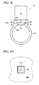
- the bypass valve 4 is arranged in such a manner that the valve body 41 can be fitted in and inserted into the branch hole 3c as illustrated in FIG. 3B and in such a manner that the valve body 41 can be away from the branch hole 3c and the branch hole 3c can communicate with the bypass conduit 3b as illustrated in FIG. 3C .
- a state where the valve body 41 is fitted in the branch hole 3c is referred to as the closed state
- a state where the valve body 41 is away from the branch hole 3c is referred to as the open state.
- the actuator 42 supports the valve body 41 using a driving shaft 42a, and is capable of moving the valve body 41 in a longitudinal direction of the driving shaft 42a based on the control by the electronic control unit 104.
- the valve body 41 (component illustrated with the oblique lines in FIGS. 3A to 3C ) is formed with the inner surface 41a so as to form one curved surface along with the inner wall 32a of the scroll section 32 in, for example, the closed state. That is, the inner surface 41 a of the valve body 41 is formed so as to form a curved surface continuing from the inner wall 32a of the scroll section 32 in the closed state. In this manner, by forming the inner surface 41a along the inner wall 32a of the scroll section 32 in the closed state, a recessed space in the scroll section 32 can be buried to prevent pressure loss and foreign material accumulation, reducing of pressure loss can be suppressed, and it is possible to inhibit the bypass conduit from being mixed with foreign material.
- FIG. 4 is a view in which the efficiency of the turbocharger 1 according to the first embodiment and the efficiency of a turbocharger according to the related art are compared to each other to illustrate the difference in efficiency.
- the horizontal axis illustrates a flow rate of the compressor 3
- the vertical axis illustrates the efficiency of the turbocharger 1.
- the solid line and the dashed line illustrate the embodiment and the related art, respectively.
- the turbocharger 1 according to the embodiment has higher efficiency than the turbocharger according to the related art regardless of the flow rate.
- the former is more effective in a case where the flow rate is relatively low.
- the pressure loss caused by the recess is larger when the flow rate is low, and thus it is clearly shown that the pressure loss is improved by the embodiment.
- FIGS. 5A to 5D Another embodiment of the present invention will be described with reference to FIGS. 5A to 5D .
- the inner surface 41 a of the valve body 41 forms a flat surface along the inner wall of the scroll section 32 in the closed state.
- the second embodiment has substantially the same effect as the first embodiment, and processing can be facilitated when the valve body 41 is manufactured and the costs can be reduced.
- the bypass valve 4 according to a third embodiment has a flange portion 41b where the valve body 41 is locked to the outer wall 32b of the scroll section 32 in the closed state.
- the closed state can be entered by bringing the flange portion 41b into contact with and by locking the flange portion to the outer wall 32b of the scroll section 32.
- the bypass valve 4 has a conical surface where the diameter of the branch hole 3c increases from the inner wall 32a of the scroll section 32 toward the outer wall 32b, and the valve body 41 has an inclined surface 41c that corresponds to the conical surface.
- the inclined surface 41c is formed by the similarly shaped conical surface so as to fit the shape of the branch hole 3c. According to the bypass valve 4 of the fourth embodiment, it is possible to form a sufficient gap between the valve body 41 and the branch hole 3c with the small amount of movement of the valve body 41, to reduce the stroke amount of the driving shaft 42a when switching between the open state and the closed state, and to improve the speed of response.
- bypass valve 4 of the fourth embodiment it is possible to prevent the valve body 41 from protruding in the scroll section 32 by mistake by bringing the conical surface of the branch hole 3c into contact with the inclined surface 41c of the valve body 41, and thus the same effect can be achieved as the above-described flange portion 41b.
- the bypass valve 4 As illustrated in FIG. 5D , the bypass valve 4 according to a fifth embodiment has a rectangular columnar surface that extends from the inner wall 32a of the scroll section 32 toward the outer wall 32b, and the valve body 41 has a side surface 41d that corresponds to the columnar surface.
- FIG. 5D illustrates a state where the branch hole 3c and the valve body 41 are viewed from inside the scroll section 32.
- the bypass valve 4 according to the first embodiment illustrated in FIG. 1 has a circular columnar surface where the branch hole 3c extends from the inner wall 32a of the scroll section 32 toward the outer wall 32b, and the valve body 41 has the side surface that corresponds to the columnar surface.
- the inner surface 41 a might have a deviated phase so as not to be the curved surface continuing from the inner wall 32a of the scroll section 32. Therefore, in order to ensure the continuity of the curved surface, it is preferable that the phase of the valve body 41 be controlled or the valve body 41 not rotate about the driving shaft 42a.
- the branch hole 3c has a rectangular cross section, and thus it is possible to forcibly match the phase if the valve body 41 is fitted in the branch hole 3c, and it is possible to easily form the curved surface continuing from the inner wall 32a of the scroll section 32.
- a tip end portion of the valve body 41 may have a tapered shape that has a decreasing diameter, or a pyramid surface may be formed in the branch hole 3c and the valve body 41 may be formed to have a shape corresponding to the pyramid surface as is the case with the branch hole 3c described in the fourth embodiment.
- the branch hole 3c has an oblong cross section instead of the rectangular cross section, the same effect as the fifth embodiment is achieved by configuring the bypass valve 4 in the same manner.
- FIGS. 6A and 6B Like reference numerals are used to refer to the same elements as illustrated in FIGS. 1 to 3C , and a redundant description thereof will be omitted here.
- the engine driving system 100 including the turbocharger 1 according to the sixth embodiment of the present invention is mounted with an EGR system 200, and, as illustrated in FIG. 6A , includes the air cleaner 101 that removes the fine foreign material in the intake air, the turbocharger 1 that compresses the intake air, the engine 102 that is driven by the compressed air and fuel, the after-treatment device 103 that removes the harmful components generated in and discharged from the combustion chamber of the engine, and the electronic control unit (ECU) 104 that controls the turbocharger 1, the engine 102, and the EGR system 200.
- ECU electronice control unit
- the EGR system 200 has an EGR cooler 201 that lowers the temperature of the exhaust gas, and an EGR valve 202 that returns some of discharge gas discharged from the engine 102 to the air inlet 33 side of the compressor 3.
- the EGR valve 202 is opened and closed based on the control by the electronic control unit 104.
- the configuration and operation of the EGR system 200 is the same as EGR systems in the related art, and thus a redundant description will be omitted here.
- the valve body 41 has a tapered portion 41e on a back surface, the diameter thereof increasing from the driving shaft 42a of the actuator 42 toward an outer edge portion of the valve body 41.
- an intake pipe on an upstream side of the compressor 3 contains not only clean air from which dust and the like is removed by the air cleaner 101 but also gas containing foreign materials such as blow-by gas and EGR gas.
- the blow-by gas is gas that flows into the intake pipe via an oil separator from an engine main body, and contains oil mist and metal powder.
- the EGR gas is gas that flows into the intake pipe through the EGR system from an exhaust pipe, and contains soot and unburnt gas.
- the air that is taken in by the compressor 3 contains various foreign materials and moisture.
- the bypass valve 4 is operated, the air containing the foreign material and moisture also flows into the bypass conduit 3b.
- the foreign materials might stick to the back surface of the valve body 41 and the moisture might be attached in a frozen state.
- the bypass valve 4 is operated in that state, there is a possibility that the valve body 41 might not be sufficiently opened due to the foreign materials and that the foreign material might be crushed or dropped out during the opening and closing of the valve body 41 to flow into the bypass conduit 3b.
- the impeller 31 of the compressor 3 might be damaged.
- the valve body 41 may be capable of rotating about the driving shaft 42a in the closed state so that the valve body 41 is opened and closed by physically releasing the sticking of the valve body 41.
- the recessed space in the scroll section can be buried to prevent the pressure loss and foreign material accumulation, reducing of pressure loss can be suppressed, and it is possible to inhibit the bypass conduit from being mixed with the foreign materials. Therefore, the operating efficiency can be improved.
Landscapes
- Engineering & Computer Science (AREA)
- Mechanical Engineering (AREA)
- General Engineering & Computer Science (AREA)
- Chemical & Material Sciences (AREA)
- Combustion & Propulsion (AREA)
- Life Sciences & Earth Sciences (AREA)
- Sustainable Development (AREA)
- Supercharger (AREA)
- Rotary Pumps (AREA)
- Exhaust-Gas Circulating Devices (AREA)
Abstract
Description
- The present invention relates to a bypass valve and a turbocharger. More particularly, the present invention relates to a bypass valve that is capable of suppressing reducing of pressure loss, and a turbocharger using the bypass valve.
- A turbocharger (for example, a turbocharger) is a device that increases the output of an engine by driving a turbine with the exhaust energy of the engine, driving a compressor coaxially linked to the axis of rotation thereof to compress air, and supplying high-density compressed air to the engine. A turbocharger in general includes a turbine housing that forms an outer shell of the turbine, a center housing (or a bearing housing) that rotatably supports the axis of rotation (or a shaft), and a compressor housing that forms an outer shell of the compressor. Also, the compressor housing has a scroll section which is formed in a spiral shape about the axis of rotation of an impeller of the compressor. The compressor compresses air taken in from an axial direction, supplies the compressed air from a circumferential end surface of the impeller to the scroll section, and discharges the compressed air out of the scroll section.
- In the turbocharger (so-called turbocharger) that is mounted on a vehicle such as an automobile, an engine side is shifted to a low rotational state by an accelerator off signal in a case where the vehicle is rapidly decelerated from high-speed driving, and thus the compressed air in a scroll is less likely to be transferred to the engine. Also, the intake amount decreases due to the compressed air remaining in the scroll. However, since inertia causes the turbocharger to continue rotating, the compressor enters a surge state. In order to control the surge state, some turbochargers have a bypass conduit that connects the scroll section of the compressor housing with an intake port of the compressor, and a bypass valve that performs the opening and closing of the bypass conduit. In this configuration, the bypass valve is opened, the compressed air in the scroll section of the compressor housing is returned to the intake port of the compressor when the vehicle is rapidly decelerated (for example, refer to
Patent Document 1 and Patent Document 2). -
Patent Document 1 discloses the bypass valve in which a valve seat is arranged in a casing of the turbocharger that is routable via a bypass passage, the bypass passage is closed by a seal lip when a valve unit is lowered onto the valve seat, and a discharge side of the turbocharger controlled by high pressure is separated from an intake side controlled by low pressure. - The Background Art section of
Patent Document 2 discloses a configuration in which a bypass pipe connecting an intake pipe on a downstream side of the compressor of the turbocharger with an intake pipe on an upstream side, and a low pressure exhaust gas recirculation (EGR) system connecting an exhaust pipe on a downstream side of the turbine of the turbocharger with the intake pipe on the upstream side of the compressor of the turbocharger are arranged. The bypass valve performing the opening and closing of the bypass pipe is arranged in the bypass pipe, and an EGR pipe connecting the exhaust pipe with the intake pipe, an EGR valve performing the opening and closing thereof, and an EGR cooler are arranged in the low pressure EGR system. -
- [Patent Document 1] Japanese Unexamined Patent Application, First Publication No.
2007-71207 - [Patent Document 2] Japanese Unexamined Patent Application, First Publication No.
2010-265854 - However, the bypass valve of above-described
Patent Document 1 is arranged in the scroll section of the compressor housing in many cases, and a passage is formed to penetrate part of the scroll section and the bypass valve is opened and closed outside the casing thereof. Therefore, in the turbocharger including the bypass valve, a recessed space is present in part (inside the bypass valve) of the scroll section, the flow of the compressed air is impeded, and thus there is a possibility that pressure loss might be generated and the operating efficiency of the turbocharger might decrease. - Also, in the turbocharger including the EGR system of above-described
Patent Document 2, not only clean air from which dust and the like is removed by an air cleaner but also gas containing foreign materials such as blow-by gas and EGR gas is contained in the intake pipe on the upstream side of the compressor. The blow-by gas is gas that flows into the intake pipe via an oil separator from an engine main body, and contains oil mist and metal powder. The EGR gas is gas that flows into the intake pipe through the low pressure EGR system from an exhaust pipe, and contains soot and unburnt gas. Therefore, in the turbocharger including the bypass valve, the recessed space is present in part (inside the bypass valve) of the scroll section, the foreign materials contained in the above-described gas are likely to be accumulated and the bypass conduit is likely to be mixed with foreign material. - The present invention has been made in view of the above circumstances, and an object thereof is to provide a bypass valve and a turbocharger capable of suppressing reducing of pressure loss, inhibiting the bypass conduit from being mixed with foreign materials, and improving the operating efficiency.
- According to a first aspect of the present invention, there is provided a bypass valve that diverts some of compressed air in a scroll section to an upstream side of the scroll section via a bypass conduit in an open state and sends the compressed air in the scroll section to a downstream side in a closed state, the bypass valve including a valve body that is fittable in a branch hole in which the scroll section communicates with the bypass conduit, and an actuator that moves the valve body between the closed state where the valve body is fitted in the branch hole and the open state where the valve body is away from the branch hole, in which the valve body forms an inner surface along an inner wall of the scroll section in the closed state.
- According to a second aspect of the present invention, there is provided a turbocharger including a gas turbine that rotates a moving blade with exhaust gas supplied from an engine, and a compressor that takes in air with an impeller that is coaxially connected to the moving blade, in which a compressor housing that forms an outer shell of the compressor has a scroll section which is formed in a spiral shape about an axis of rotation of the impeller, and the turbocharger further includes a bypass valve that diverts some of the compressed air in a scroll section to an upstream side of the scroll section via a bypass conduit in an open state and sends the compressed air in the scroll section to a downstream side in a closed state, the bypass valve having a valve body that is fittable in a branch hole in which the scroll section communicates with the bypass conduit, and an actuator that moves the valve body between the closed state where the valve body is fitted in the branch hole and the open state where the valve body is away from the branch hole, in which the valve body forms an inner surface along an inner wall of the scroll section in the closed state.
- In the bypass valve and the turbocharger according to the above-described first and second aspects of the present invention, the inner surface of the valve body may form one curved surface along with the inner wall of the scroll section, or to form a flat surface along the inner wall of the scroll section in the closed state. Also, the valve body may include a flange portion that is locked to an outer wall of the scroll section in the closed state.
- The branch hole may include a conical surface whose diameter increases from the inner wall of the scroll section toward the outer wall, and the valve body may include an inclined surface that corresponds to the conical surface. Also, the branch hole may include a circular or rectangular columnar surface that extends from the inner wall of the scroll section toward the outer wall, and the valve body may include a side surface that corresponds to the columnar surface.
- The valve body may include a tapered portion on a back surface, the diameter of the tapered portion increasing from a driving shaft of the actuator toward an outer edge portion of the valve body.
- According to the above-described bypass valve and the turbocharger according to the present invention, the valve body is fitted in the branch hole and forms a conduit surface along the inner wall of the scroll section in the closed state of the bypass conduit. Therefore, a recessed space in the scroll section can be buried to prevent pressure loss and foreign material accumulation, reducing of pressure loss can be suppressed, it is possible to inhibit the bypass conduit from being mixed with foreign material, and the operating efficiency can be improved.
-
-
FIG. 1 is a cross-sectional view of a turbocharger according to a first embodiment of the present invention. -
FIG. 2 is a configuration diagram of an engine driving system including the turbocharger illustrated inFIG. 1 . -
FIG. 3A is a perspective view of a bypass valve illustrated inFIG. 1 . -
FIG. 3B is a cross-sectional view of the bypass valve illustrated inFIG. 1 in a closed state. -
FIG. 3C is a cross-sectional view of the bypass valve illustrated inFIG. 1 in an open state. -
FIG. 4 is a view in which the efficiency of the turbocharger illustrated inFIG. 1 with respect to a flow rate and the efficiency of a turbocharger according to the related art with respect to a flow rate are compared to each other. -
FIG. 5A is an explanatory view of a second embodiment of a bypass valve according to another embodiment of the present invention. -
FIG. 5B is an explanatory view of a third embodiment of a bypass valve according to another embodiment of the present invention. -
FIG. 5C is an explanatory view of a fourth embodiment of a bypass valve according to another embodiment of the present invention. -
FIG. 5D is an explanatory view of a fifth embodiment of a bypass valve according to another embodiment of the present invention. -
FIG. 6A is a configuration diagram of an engine driving system including a turbocharger according to a sixth embodiment of the present invention. -
FIG. 6B is a cross-sectional view of a bypass valve according to the sixth embodiment of the present invention. - Hereinafter, embodiments of the present invention will be described with reference to
FIGS. 1 to 6B . - As illustrated in
FIGS. 1 and2 , aturbocharger 1 according to a first embodiment of the present invention includes agas turbine 2 that rotates movingblades 21 with exhaust gas supplied from anengine 102, and acompressor 3 that takes in air with an impeller 31 that is coaxially linked to the movingblades 21. Acompressor housing 3a that forms an outer shell of thecompressor 3 has ascroll section 32 which is formed in a spiral shape about an axis of rotation of the impeller 31. Also, in thecompressor housing 3a, abypass valve 4 that diverts some of the compressed air in thescroll section 32 to an upstream side of thescroll section 32 via abypass conduit 3b in an open state and sends the compressed air in thescroll section 32 to a downstream side in a closed state is formed. Thebypass valve 4 has avalve body 41 that is configured to be fittable in abranch hole 3c in which thescroll section 32 communicates with thebypass conduit 3b, and anactuator 42 that moves thevalve body 41 between the closed state where thevalve body 41 is fitted in thebranch hole 3c and the open state where thevalve body 41 is away from thebranch hole 3c. Thevalve body 41 forms aninner surface 41a along aninner wall 32a of thescroll section 32 in the closed state. - The
turbocharger 1 illustrated inFIG. 1 is an example of fluid machineries. Theturbocharger 1 includes aturbine housing 2a that forms an outer shell of thegas turbine 2, a bearinghousing 5a that rotatably supports arotor shaft 5, and thecompressor housing 3a that forms the outer shell of thecompressor 3. Theturbocharger 1 has the same configuration as, for example, vehicle turbochargers (so-called turbochargers) according to the related art. - The
gas turbine 2 is a centrifugal turbine, and has ascroll section 23 that is formed in a spiral shape about an axis of rotation of adisk wheel 22 which has a plurality of movingblades 21, anexhaust gas inlet 24 that supplies the exhaust gas to thescroll section 23, and anexhaust gas outlet 25 that discharges the exhaust gas supplied to thedisk wheel 22 in an extension direction of therotor shaft 5. - The
compressor 3 is a so-called centrifugal compressor, and has thescroll section 32 that is formed in a spiral shape about the axis of rotation of the impeller 31, an air inlet 33 that supplies air from the extension direction of therotor shaft 5, and anair outlet 34 that discharges air compressed by the impeller 31 out of thescroll section 32. Also, on a surface of the impeller 31, a plurality ofcompressor impellers 35 is integrally formed by precision casting or the like. Also, thebypass valve 4 is provided in part of thescroll section 32. When thebypass valve 4 is opened, some of the compressed air in thescroll section 32 is diverted to the air inlet 33. - The
rotor shaft 5 has alarge diameter portion 51 and asmall diameter portion 52, and one end of thelarge diameter portion 51 is joined to thedisk wheel 22 and is integrated with the movingblades 21 after finishing, hardening treatment, and outer diameter grinding are performed as is the case with the related art. Also, between thelarge diameter portion 51 and thesmall diameter portion 52, athrust collar 53 and the like are arranged to form a thrust bearing. The impeller 31 is fitted in thesmall diameter portion 52 of therotor shaft 5, and fixed by ashaft end nut 54. - Also, as illustrated in
FIG. 1 , theturbocharger 1 is built into anengine driving system 100 illustrated inFIG. 2 . As illustrated inFIG. 2 , theengine driving system 100 includes anair cleaner 101 that removes fine foreign materials in intake air, theturbocharger 1 that compresses the intake air, theengine 102 that is driven by the compressed air and fuel, an after-treatment device 103 that removes harmful components generated in and discharged from a combustion chamber of theengine 102, and an electronic control unit (ECU) 104 that controls theturbocharger 1 and theengine 102. - The
turbocharger 1 collects the energy of the exhaust gas using thegas turbine 2, puts thecompressor 3 into operation, and supplies the compressed air to theengine 102 for an increase in output. Also, the opening and closing of thebypass valve 4 that is arranged in thescroll section 32 of thecompressor 3 is controlled by theelectronic control unit 104. For example, in a state where a vehicle mounted with theengine driving system 100 is rapidly decelerated from high-speed driving, theelectronic control unit 104 opens thebypass valve 4 so as to suppress a surge state, and returns some of the compressed air in thescroll section 32 to the air inlet 33 side. In a normal state, thebypass valve 4 is closed, and the entire compressed air in thescroll section 32 is supplied from theair outlet 34 to theengine 102. - The
engine 102 is, for example, a diesel engine or a gasoline engine mounted on a vehicle. Theengine 102 controls the amount of the compressed air and the fuel supplied depending on operating conditions. The control is performed by theelectronic control unit 104. Theengine 102 is controlled based on an air-fuel ratio (air mass/fuel mass). Theair cleaner 101 is a device that removes the fine foreign materials in the air which is taken in from outside and supplies clean air to theturbocharger 1, and the after-treatment device 103 is a device that detoxifies the harmful components generated in and discharged from the combustion chamber of theengine 102 and discharges the result outside. - As illustrated in
FIGS. 1 and3A , thebypass conduit 3b is formed in thecompressor housing 3a, and thebranch hole 3c is formed so as to communicate thebypass conduit 3b with thescroll section 32. Thebypass valve 4 is connected to thecompressor housing 3a so as to face thebypass conduit 3b. - By the
actuator 42, thebypass valve 4 is arranged in such a manner that thevalve body 41 can be fitted in and inserted into thebranch hole 3c as illustrated inFIG. 3B and in such a manner that thevalve body 41 can be away from thebranch hole 3c and thebranch hole 3c can communicate with thebypass conduit 3b as illustrated inFIG. 3C . In the embodiment, a state where thevalve body 41 is fitted in thebranch hole 3c is referred to as the closed state, and a state where thevalve body 41 is away from thebranch hole 3c is referred to as the open state. Theactuator 42 supports thevalve body 41 using a drivingshaft 42a, and is capable of moving thevalve body 41 in a longitudinal direction of the drivingshaft 42a based on the control by theelectronic control unit 104. - The valve body 41 (component illustrated with the oblique lines in
FIGS. 3A to 3C ) is formed with theinner surface 41a so as to form one curved surface along with theinner wall 32a of thescroll section 32 in, for example, the closed state. That is, theinner surface 41 a of thevalve body 41 is formed so as to form a curved surface continuing from theinner wall 32a of thescroll section 32 in the closed state. In this manner, by forming theinner surface 41a along theinner wall 32a of thescroll section 32 in the closed state, a recessed space in thescroll section 32 can be buried to prevent pressure loss and foreign material accumulation, reducing of pressure loss can be suppressed, and it is possible to inhibit the bypass conduit from being mixed with foreign material. - Herein,
FIG. 4 is a view in which the efficiency of theturbocharger 1 according to the first embodiment and the efficiency of a turbocharger according to the related art are compared to each other to illustrate the difference in efficiency. InFIG. 4 , the horizontal axis illustrates a flow rate of thecompressor 3, and the vertical axis illustrates the efficiency of theturbocharger 1. Also, the solid line and the dashed line illustrate the embodiment and the related art, respectively. It can be easily understood fromFIG. 4 that theturbocharger 1 according to the embodiment has higher efficiency than the turbocharger according to the related art regardless of the flow rate. In particular, the former is more effective in a case where the flow rate is relatively low. In a case where thescroll section 32 has a recess, the pressure loss caused by the recess is larger when the flow rate is low, and thus it is clearly shown that the pressure loss is improved by the embodiment. - Hereinafter, another embodiment of the present invention will be described with reference to
FIGS. 5A to 5D . - As illustrated in
FIG. 5A , in thebypass valve 4 according to a second embodiment of the present invention, theinner surface 41 a of thevalve body 41 forms a flat surface along the inner wall of thescroll section 32 in the closed state. The second embodiment has substantially the same effect as the first embodiment, and processing can be facilitated when thevalve body 41 is manufactured and the costs can be reduced. - As illustrated in
FIG. 5B , thebypass valve 4 according to a third embodiment has aflange portion 41b where thevalve body 41 is locked to theouter wall 32b of thescroll section 32 in the closed state. In thebypass valve 4 according to the first embodiment, it is necessary to set the stroke amount of the drivingshaft 42a in advance so as to properly switch between the open state and the closed state. With respect thereto, according to thebypass valve 4 of the third embodiment, the closed state can be entered by bringing theflange portion 41b into contact with and by locking the flange portion to theouter wall 32b of thescroll section 32. - Therefore, by arranging a pressure sensor and a load sensor in the
bypass valve 4, it is possible to stop theactuator 42 after detecting that theflange portion 41b of thevalve body 41 is in contact with theouter wall 32b of thescroll section 32, and it is possible to easily control the stroke amount of the drivingshaft 42a. - As illustrated in
FIG. 5C , thebypass valve 4 according to a fourth embodiment has a conical surface where the diameter of thebranch hole 3c increases from theinner wall 32a of thescroll section 32 toward theouter wall 32b, and thevalve body 41 has aninclined surface 41c that corresponds to the conical surface. Theinclined surface 41c is formed by the similarly shaped conical surface so as to fit the shape of thebranch hole 3c. According to thebypass valve 4 of the fourth embodiment, it is possible to form a sufficient gap between thevalve body 41 and thebranch hole 3c with the small amount of movement of thevalve body 41, to reduce the stroke amount of the drivingshaft 42a when switching between the open state and the closed state, and to improve the speed of response. - Also, according to the
bypass valve 4 of the fourth embodiment, it is possible to prevent thevalve body 41 from protruding in thescroll section 32 by mistake by bringing the conical surface of thebranch hole 3c into contact with theinclined surface 41c of thevalve body 41, and thus the same effect can be achieved as the above-describedflange portion 41b. - As illustrated in
FIG. 5D , thebypass valve 4 according to a fifth embodiment has a rectangular columnar surface that extends from theinner wall 32a of thescroll section 32 toward theouter wall 32b, and thevalve body 41 has aside surface 41d that corresponds to the columnar surface.FIG. 5D illustrates a state where thebranch hole 3c and thevalve body 41 are viewed from inside thescroll section 32. - The
bypass valve 4 according to the first embodiment illustrated inFIG. 1 has a circular columnar surface where thebranch hole 3c extends from theinner wall 32a of thescroll section 32 toward theouter wall 32b, and thevalve body 41 has the side surface that corresponds to the columnar surface. In the first embodiment, in a state where thevalve body 41 rotates about the drivingshaft 42a, there is a possibility that theinner surface 41 a might have a deviated phase so as not to be the curved surface continuing from theinner wall 32a of thescroll section 32. Therefore, in order to ensure the continuity of the curved surface, it is preferable that the phase of thevalve body 41 be controlled or thevalve body 41 not rotate about the drivingshaft 42a. - According to the
bypass valve 4 of the above-described fifth embodiment, thebranch hole 3c has a rectangular cross section, and thus it is possible to forcibly match the phase if thevalve body 41 is fitted in thebranch hole 3c, and it is possible to easily form the curved surface continuing from theinner wall 32a of thescroll section 32. Also, since thevalve body 41 is reliably fitted in thebranch hole 3c, a tip end portion of thevalve body 41 may have a tapered shape that has a decreasing diameter, or a pyramid surface may be formed in thebranch hole 3c and thevalve body 41 may be formed to have a shape corresponding to the pyramid surface as is the case with thebranch hole 3c described in the fourth embodiment. Even in a case where thebranch hole 3c has an oblong cross section instead of the rectangular cross section, the same effect as the fifth embodiment is achieved by configuring thebypass valve 4 in the same manner. - Hereinafter, a sixth embodiment of the present invention will be described with reference to
FIGS. 6A and 6B . Like reference numerals are used to refer to the same elements as illustrated inFIGS. 1 to 3C , and a redundant description thereof will be omitted here. - The
engine driving system 100 including theturbocharger 1 according to the sixth embodiment of the present invention is mounted with anEGR system 200, and, as illustrated inFIG. 6A , includes theair cleaner 101 that removes the fine foreign material in the intake air, theturbocharger 1 that compresses the intake air, theengine 102 that is driven by the compressed air and fuel, the after-treatment device 103 that removes the harmful components generated in and discharged from the combustion chamber of the engine, and the electronic control unit (ECU) 104 that controls theturbocharger 1, theengine 102, and theEGR system 200. - Also, the
EGR system 200 has an EGR cooler 201 that lowers the temperature of the exhaust gas, and anEGR valve 202 that returns some of discharge gas discharged from theengine 102 to the air inlet 33 side of thecompressor 3. TheEGR valve 202 is opened and closed based on the control by theelectronic control unit 104. The configuration and operation of theEGR system 200 is the same as EGR systems in the related art, and thus a redundant description will be omitted here. - As illustrated in
FIG. 6B , in thebypass valve 4 according to the sixth embodiment, thevalve body 41 has a taperedportion 41e on a back surface, the diameter thereof increasing from the drivingshaft 42a of theactuator 42 toward an outer edge portion of thevalve body 41. As described above, in a case where theEGR system 200 or the like is provided, an intake pipe on an upstream side of thecompressor 3 contains not only clean air from which dust and the like is removed by theair cleaner 101 but also gas containing foreign materials such as blow-by gas and EGR gas. The blow-by gas is gas that flows into the intake pipe via an oil separator from an engine main body, and contains oil mist and metal powder. The EGR gas is gas that flows into the intake pipe through the EGR system from an exhaust pipe, and contains soot and unburnt gas. - In this manner, the air that is taken in by the
compressor 3 contains various foreign materials and moisture. In a case where thebypass valve 4 is operated, the air containing the foreign material and moisture also flows into thebypass conduit 3b. As a result, there is a possibility that the foreign materials might stick to the back surface of thevalve body 41 and the moisture might be attached in a frozen state. In a case where thebypass valve 4 is operated in that state, there is a possibility that thevalve body 41 might not be sufficiently opened due to the foreign materials and that the foreign material might be crushed or dropped out during the opening and closing of thevalve body 41 to flow into thebypass conduit 3b. In a case where the foreign material is a relatively large lump, there is a concern that the impeller 31 of thecompressor 3 might be damaged. - Herein, by forming the tapered
portion 41e on the flat surface of thevalve body 41, it is possible to prevent the foreign material from piling up and to prevent the moisture from accumulating, and thus it is possible to easily prevent the foreign materials and ice from sticking. Also, in a case where thevalve body 41 is in the closed state and the foreign material clogs the space between thevalve body 41 and thebranch hole 3c thereby sticking them together to impede the opening and closing of thevalve body 41, thevalve body 41 may be capable of rotating about the drivingshaft 42a in the closed state so that thevalve body 41 is opened and closed by physically releasing the sticking of thevalve body 41. - The present invention is not limited to the above-described embodiments but the above-described embodiments may be appropriately combined with each other. Also, various changes may be made without departing from the scope of the present invention.
- According to the bypass valve and the turbocharger of the present invention, the recessed space in the scroll section can be buried to prevent the pressure loss and foreign material accumulation, reducing of pressure loss can be suppressed, and it is possible to inhibit the bypass conduit from being mixed with the foreign materials. Therefore, the operating efficiency can be improved.
-
- 1
- TURBOCHARGER
- 2
- GAS TURBINE
- 3
- COMPRESSOR
- 3a
- COMPRESSOR HOUSING
- 3b
- BYPASS CONDUIT
- 3c
- BRANCH HOLE
- 4
- BYPASS VALVE
- 21
- MOVING BLADE
- 31
- IMPELLER
- 32
- SCROLL SECTION
- 32a
- INNER WALL
- 32b
- OUTER WALL
- 41
- VALVE BODY
- 41a
- INNER SURFACE
- 41b
- FLANGE PORTION
- 41c
- INCLINED SURFACE
- 41d
- SIDE SURFACE
- 41e
- TAPERED PORTION
- 42
- ACTUATOR
- 42a
- DRIVING SHAFT
- 102
- ENGINE
Claims (8)
- A bypass valve that diverts some of compressed air in a scroll section to an upstream side of the scroll section via a bypass conduit in an open state and sends the compressed air in the scroll section to a downstream side in a closed state, the bypass valve comprising:a valve body that is fittable in a branch hole in which the scroll section communicates with the bypass conduit; andan actuator that moves the valve body between the closed state where the valve body is fitted in the branch hole and the open state where the valve body is away from the branch hole,wherein the valve body forms an inner surface along an inner wall of the scroll section in the closed state.
- The bypass valve according to claim 1,
wherein the inner surface of the valve body forms one curved surface along with the inner wall of the scroll section in the closed state. - The bypass valve according to claim 1,
wherein the inner surface of the valve body forms a flat surface along the inner wall of the scroll section in the closed state. - The bypass valve according to claim 1,
wherein the valve body includes a flange portion that is locked to an outer wall of the scroll section in the closed state. - The bypass valve according to claim 1,
wherein the branch hole includes a conical surface whose diameter increases from the inner wall of the scroll section toward the outer wall, and the valve body includes an inclined surface that corresponds to the conical surface. - The bypass valve according to claim 1,
wherein the branch hole includes a circular or rectangular columnar surface that extends from the inner wall of the scroll section toward the outer wall, and the valve body includes a side surface that corresponds to the columnar surface. - The bypass valve according to claim 1,
wherein the valve body includes a tapered portion on a back surface, the diameter of the tapered portion increasing from a driving shaft of the actuator toward an outer edge portion of the valve body. - A turbocharger comprising the bypass valve according to any one of claims 1 to 7, the turbocharger comprising:a gas turbine that rotates a moving blade with exhaust gas supplied from an engine; anda compressor that takes in air with an impeller that is coaxially connected to the moving blade,wherein a compressor housing that forms an outer shell of the compressor has a scroll section which is formed in a spiral shape about an axis of rotation of the impeller.
Applications Claiming Priority (2)
| Application Number | Priority Date | Filing Date | Title |
|---|---|---|---|
| JP2011110296A JP2012241558A (en) | 2011-05-17 | 2011-05-17 | Bypass valve and supercharger |
| PCT/JP2012/062273 WO2012157598A1 (en) | 2011-05-17 | 2012-05-14 | Bypass valve and supercharger |
Publications (3)
| Publication Number | Publication Date |
|---|---|
| EP2711522A1 true EP2711522A1 (en) | 2014-03-26 |
| EP2711522A4 EP2711522A4 (en) | 2014-11-12 |
| EP2711522B1 EP2711522B1 (en) | 2017-06-28 |
Family
ID=47176915
Family Applications (1)
| Application Number | Title | Priority Date | Filing Date |
|---|---|---|---|
| EP12786338.9A Not-in-force EP2711522B1 (en) | 2011-05-17 | 2012-05-14 | Bypass valve and supercharger |
Country Status (6)
| Country | Link |
|---|---|
| US (1) | US9476351B2 (en) |
| EP (1) | EP2711522B1 (en) |
| JP (1) | JP2012241558A (en) |
| KR (1) | KR20140002049A (en) |
| CN (1) | CN103608561A (en) |
| WO (1) | WO2012157598A1 (en) |
Cited By (1)
| Publication number | Priority date | Publication date | Assignee | Title |
|---|---|---|---|---|
| JP2015090111A (en) * | 2013-11-06 | 2015-05-11 | 本田技研工業株式会社 | Flow passage member |
Families Citing this family (18)
| Publication number | Priority date | Publication date | Assignee | Title |
|---|---|---|---|---|
| JP5953239B2 (en) * | 2013-01-23 | 2016-07-20 | 株式会社オティックス | Compressor housing for supercharger and method for manufacturing the same |
| CN105283674B (en) | 2013-08-06 | 2017-08-25 | 株式会社Ihi | Centrifugal compressors and superchargers |
| US9611857B2 (en) * | 2014-04-24 | 2017-04-04 | Control Components, Inc. | Dead time reducer for piston actuator |
| US10155592B2 (en) | 2014-05-05 | 2018-12-18 | Hamilton Sundstrand Corporation | Environmental control system with air cycle machine bypass shutoff valves |
| JP6288267B2 (en) * | 2014-06-02 | 2018-03-07 | 株式会社Ihi | Bearing structure and turbocharger |
| CN105840313B (en) * | 2014-08-13 | 2019-04-09 | 安萨尔多能源公司 | Repair method and kit for gas turbine power plant |
| CN104131887A (en) * | 2014-08-15 | 2014-11-05 | 无锡科博增压器有限公司 | Anti-surge structure for deceleration of pressurizer |
| CN104329161B (en) * | 2014-09-18 | 2017-01-18 | 北京航空航天大学 | High-stability anti-surge regulating system and method for turbocharger of aviation piston engine |
| CN104481673B (en) * | 2014-12-29 | 2017-03-08 | 无锡康明斯涡轮增压技术有限公司 | Exhaust-driven turbo-charger exhaust-gas turbo charger volute by-pass collar |
| JP6330770B2 (en) * | 2015-09-25 | 2018-05-30 | マツダ株式会社 | Control device for turbocharged engine |
| US9829006B2 (en) * | 2015-10-14 | 2017-11-28 | Hamilton Sundstrand Corporation | Air cycle machine compressor housing |
| US10344665B2 (en) * | 2016-01-22 | 2019-07-09 | Garrett Transportation I Inc. | Compressor recirculation system having compressor inlet recirculation duct configured to reduce noise from Rossiter excitation and cavity acoustic resonance |
| JP2017155664A (en) * | 2016-03-02 | 2017-09-07 | 株式会社豊田自動織機 | Centrifugal compressor |
| JP7042650B2 (en) * | 2018-02-28 | 2022-03-28 | 三菱重工マリンマシナリ株式会社 | Turbocharger |
| WO2020008615A1 (en) | 2018-07-06 | 2020-01-09 | 三菱重工エンジン&ターボチャージャ株式会社 | Centrifugal compressor and turbocharger |
| CN111670297B (en) | 2018-07-13 | 2022-07-26 | 三菱重工发动机和增压器株式会社 | Centrifugal compressor and turbocharger |
| CN114746636B (en) | 2019-12-17 | 2023-12-05 | 三菱重工发动机和增压器株式会社 | Compressor and turbocharger provided with same |
| JP7529620B2 (en) | 2021-06-16 | 2024-08-06 | 三菱重工エンジン&ターボチャージャ株式会社 | Pipe branching device and compressor |
Family Cites Families (18)
| Publication number | Priority date | Publication date | Assignee | Title |
|---|---|---|---|---|
| US3195805A (en) * | 1961-10-25 | 1965-07-20 | Garrett Corp | Turbocharger differential pressure control |
| JPS56167813A (en) * | 1980-05-28 | 1981-12-23 | Nissan Motor Co Ltd | Surge preventing apparatus for turbocharger |
| US4517803A (en) * | 1983-04-22 | 1985-05-21 | The Garrett Corporation | Turbocharger compressor valve |
| US5137003A (en) * | 1989-05-19 | 1992-08-11 | Mitsubishi Denki K.K. | Supercharged pressure control valve apparatus |
| JPH0482460A (en) | 1990-07-25 | 1992-03-16 | Nippon Conlux Co Ltd | Automatic telephone incoming response system |
| GB2246395A (en) * | 1990-07-26 | 1992-01-29 | Garrett Automotive Limited | Noise attenuation in a turbocharger |
| JPH0482460U (en) * | 1990-11-28 | 1992-07-17 | ||
| JPH082460A (en) | 1994-06-17 | 1996-01-09 | Ougi Kogyo:Kk | Cup part in bell for bicycle |
| US5904471A (en) * | 1996-12-20 | 1999-05-18 | Turbodyne Systems, Inc. | Cooling means for a motor-driven centrifugal air compressor |
| JP3493989B2 (en) * | 1997-12-19 | 2004-02-03 | 日産自動車株式会社 | Centrifugal supercharger |
| DE10133669A1 (en) * | 2001-07-11 | 2003-01-30 | Daimler Chrysler Ag | Exhaust gas turbocharger in an internal combustion engine |
| JP3756135B2 (en) * | 2002-08-12 | 2006-03-15 | アドバンス電気工業株式会社 | Diaphragm valve structure |
| JP2004300965A (en) * | 2003-03-28 | 2004-10-28 | Aisin Seiki Co Ltd | Variable capacity turbocharger |
| CN100547238C (en) * | 2005-07-19 | 2009-10-07 | 上海非常化油器有限公司 | Fixed choke adjustable micro porous spray tube gas mixing regulator |
| DE102005042679B4 (en) | 2005-09-08 | 2013-04-18 | Pierburg Gmbh | Bypass valve for internal combustion engines |
| JP4708300B2 (en) * | 2006-10-10 | 2011-06-22 | トヨタ自動車株式会社 | Turbocharger |
| JP2010265854A (en) | 2009-05-18 | 2010-11-25 | Isuzu Motors Ltd | Internal combustion engine with turbocharger and control method thereof |
| DE202009007233U1 (en) * | 2009-05-20 | 2009-09-03 | Borgwarner Inc., Auburn Hills | Compressor of an exhaust gas turbocharger |
-
2011
- 2011-05-17 JP JP2011110296A patent/JP2012241558A/en active Pending
-
2012
- 2012-05-14 WO PCT/JP2012/062273 patent/WO2012157598A1/en not_active Ceased
- 2012-05-14 KR KR1020137030150A patent/KR20140002049A/en not_active Ceased
- 2012-05-14 CN CN201280023260.XA patent/CN103608561A/en active Pending
- 2012-05-14 EP EP12786338.9A patent/EP2711522B1/en not_active Not-in-force
-
2013
- 2013-11-14 US US14/079,876 patent/US9476351B2/en not_active Expired - Fee Related
Cited By (1)
| Publication number | Priority date | Publication date | Assignee | Title |
|---|---|---|---|---|
| JP2015090111A (en) * | 2013-11-06 | 2015-05-11 | 本田技研工業株式会社 | Flow passage member |
Also Published As
| Publication number | Publication date |
|---|---|
| EP2711522B1 (en) | 2017-06-28 |
| WO2012157598A1 (en) | 2012-11-22 |
| CN103608561A (en) | 2014-02-26 |
| US9476351B2 (en) | 2016-10-25 |
| EP2711522A4 (en) | 2014-11-12 |
| JP2012241558A (en) | 2012-12-10 |
| US20140069096A1 (en) | 2014-03-13 |
| KR20140002049A (en) | 2014-01-07 |
Similar Documents
| Publication | Publication Date | Title |
|---|---|---|
| EP2711522B1 (en) | Bypass valve and supercharger | |
| EP2871369B1 (en) | Compressor for supercharger of internal combustion engine | |
| US9759164B2 (en) | Fluid energy machine, in particular for an exhaust gas turbocharger of an automobile | |
| KR20100117060A (en) | Supercharger | |
| EP2642108A1 (en) | Low-pressure loop egr device | |
| CN102639837B (en) | Explosive motor | |
| CN104471209B (en) | Variable capacity supercharger and method of manufacturing variable capacity supercharger housing | |
| EP3301277B1 (en) | Turbocharger with ported turbine shroud | |
| CN103732879A (en) | Exhaust turbocharger with ball joint-wastegate-valve and stress-relieved crank arm | |
| EP2921671A1 (en) | Turbine wastegate | |
| JP2012149588A (en) | Controller for internal combustion engine | |
| EP2837791A1 (en) | Seal structure and variable displacement supercharger | |
| JP2013238144A (en) | Low-pressure loop egr device | |
| JP2012102660A (en) | Variable displacement supercharger | |
| JP2010270732A (en) | Impeller and supercharger | |
| JP5218170B2 (en) | Turbocharger | |
| US11585265B2 (en) | Surge suppression device, exhaust turbine type turbocharger and surge suppression method | |
| US9896996B2 (en) | Reducing turbocharger ice damage | |
| JP5454460B2 (en) | Exhaust gas recirculation device for an internal combustion engine provided with a valve unit and a valve unit | |
| KR101336364B1 (en) | Turbo charger for vehicle | |
| SE541037C2 (en) | A stopping arrangement, an intake and exhaust system, and a vehicle comprising such a system | |
| WO2015033844A1 (en) | Turbine, turbocharger, internal combustion engine, and ship |
Legal Events
| Date | Code | Title | Description |
|---|---|---|---|
| PUAI | Public reference made under article 153(3) epc to a published international application that has entered the european phase |
Free format text: ORIGINAL CODE: 0009012 |
|
| 17P | Request for examination filed |
Effective date: 20131121 |
|
| AK | Designated contracting states |
Kind code of ref document: A1 Designated state(s): AL AT BE BG CH CY CZ DE DK EE ES FI FR GB GR HR HU IE IS IT LI LT LU LV MC MK MT NL NO PL PT RO RS SE SI SK SM TR |
|
| DAX | Request for extension of the european patent (deleted) | ||
| A4 | Supplementary search report drawn up and despatched |
Effective date: 20141013 |
|
| RIC1 | Information provided on ipc code assigned before grant |
Ipc: F04D 27/02 20060101ALI20141007BHEP Ipc: F02B 37/16 20060101AFI20141007BHEP Ipc: F02B 39/00 20060101ALI20141007BHEP |
|
| GRAP | Despatch of communication of intention to grant a patent |
Free format text: ORIGINAL CODE: EPIDOSNIGR1 |
|
| INTG | Intention to grant announced |
Effective date: 20170118 |
|
| GRAS | Grant fee paid |
Free format text: ORIGINAL CODE: EPIDOSNIGR3 |
|
| GRAA | (expected) grant |
Free format text: ORIGINAL CODE: 0009210 |
|
| AK | Designated contracting states |
Kind code of ref document: B1 Designated state(s): AL AT BE BG CH CY CZ DE DK EE ES FI FR GB GR HR HU IE IS IT LI LT LU LV MC MK MT NL NO PL PT RO RS SE SI SK SM TR |
|
| REG | Reference to a national code |
Ref country code: GB Ref legal event code: FG4D |
|
| REG | Reference to a national code |
Ref country code: CH Ref legal event code: EP |
|
| REG | Reference to a national code |
Ref country code: AT Ref legal event code: REF Ref document number: 905058 Country of ref document: AT Kind code of ref document: T Effective date: 20170715 |
|
| REG | Reference to a national code |
Ref country code: IE Ref legal event code: FG4D |
|
| REG | Reference to a national code |
Ref country code: DE Ref legal event code: R096 Ref document number: 602012034003 Country of ref document: DE |
|
| PG25 | Lapsed in a contracting state [announced via postgrant information from national office to epo] |
Ref country code: GR Free format text: LAPSE BECAUSE OF FAILURE TO SUBMIT A TRANSLATION OF THE DESCRIPTION OR TO PAY THE FEE WITHIN THE PRESCRIBED TIME-LIMIT Effective date: 20170929 Ref country code: FI Free format text: LAPSE BECAUSE OF FAILURE TO SUBMIT A TRANSLATION OF THE DESCRIPTION OR TO PAY THE FEE WITHIN THE PRESCRIBED TIME-LIMIT Effective date: 20170628 Ref country code: NO Free format text: LAPSE BECAUSE OF FAILURE TO SUBMIT A TRANSLATION OF THE DESCRIPTION OR TO PAY THE FEE WITHIN THE PRESCRIBED TIME-LIMIT Effective date: 20170928 Ref country code: LT Free format text: LAPSE BECAUSE OF FAILURE TO SUBMIT A TRANSLATION OF THE DESCRIPTION OR TO PAY THE FEE WITHIN THE PRESCRIBED TIME-LIMIT Effective date: 20170628 Ref country code: HR Free format text: LAPSE BECAUSE OF FAILURE TO SUBMIT A TRANSLATION OF THE DESCRIPTION OR TO PAY THE FEE WITHIN THE PRESCRIBED TIME-LIMIT Effective date: 20170628 |
|
| REG | Reference to a national code |
Ref country code: NL Ref legal event code: MP Effective date: 20170628 |
|
| REG | Reference to a national code |
Ref country code: LT Ref legal event code: MG4D |
|
| REG | Reference to a national code |
Ref country code: AT Ref legal event code: MK05 Ref document number: 905058 Country of ref document: AT Kind code of ref document: T Effective date: 20170628 |
|
| PG25 | Lapsed in a contracting state [announced via postgrant information from national office to epo] |
Ref country code: SE Free format text: LAPSE BECAUSE OF FAILURE TO SUBMIT A TRANSLATION OF THE DESCRIPTION OR TO PAY THE FEE WITHIN THE PRESCRIBED TIME-LIMIT Effective date: 20170628 Ref country code: LV Free format text: LAPSE BECAUSE OF FAILURE TO SUBMIT A TRANSLATION OF THE DESCRIPTION OR TO PAY THE FEE WITHIN THE PRESCRIBED TIME-LIMIT Effective date: 20170628 Ref country code: RS Free format text: LAPSE BECAUSE OF FAILURE TO SUBMIT A TRANSLATION OF THE DESCRIPTION OR TO PAY THE FEE WITHIN THE PRESCRIBED TIME-LIMIT Effective date: 20170628 Ref country code: NL Free format text: LAPSE BECAUSE OF FAILURE TO SUBMIT A TRANSLATION OF THE DESCRIPTION OR TO PAY THE FEE WITHIN THE PRESCRIBED TIME-LIMIT Effective date: 20170628 Ref country code: BG Free format text: LAPSE BECAUSE OF FAILURE TO SUBMIT A TRANSLATION OF THE DESCRIPTION OR TO PAY THE FEE WITHIN THE PRESCRIBED TIME-LIMIT Effective date: 20170928 |
|
| PG25 | Lapsed in a contracting state [announced via postgrant information from national office to epo] |
Ref country code: AT Free format text: LAPSE BECAUSE OF FAILURE TO SUBMIT A TRANSLATION OF THE DESCRIPTION OR TO PAY THE FEE WITHIN THE PRESCRIBED TIME-LIMIT Effective date: 20170628 Ref country code: EE Free format text: LAPSE BECAUSE OF FAILURE TO SUBMIT A TRANSLATION OF THE DESCRIPTION OR TO PAY THE FEE WITHIN THE PRESCRIBED TIME-LIMIT Effective date: 20170628 Ref country code: RO Free format text: LAPSE BECAUSE OF FAILURE TO SUBMIT A TRANSLATION OF THE DESCRIPTION OR TO PAY THE FEE WITHIN THE PRESCRIBED TIME-LIMIT Effective date: 20170628 Ref country code: CZ Free format text: LAPSE BECAUSE OF FAILURE TO SUBMIT A TRANSLATION OF THE DESCRIPTION OR TO PAY THE FEE WITHIN THE PRESCRIBED TIME-LIMIT Effective date: 20170628 Ref country code: SK Free format text: LAPSE BECAUSE OF FAILURE TO SUBMIT A TRANSLATION OF THE DESCRIPTION OR TO PAY THE FEE WITHIN THE PRESCRIBED TIME-LIMIT Effective date: 20170628 |
|
| PG25 | Lapsed in a contracting state [announced via postgrant information from national office to epo] |
Ref country code: ES Free format text: LAPSE BECAUSE OF FAILURE TO SUBMIT A TRANSLATION OF THE DESCRIPTION OR TO PAY THE FEE WITHIN THE PRESCRIBED TIME-LIMIT Effective date: 20170628 Ref country code: IS Free format text: LAPSE BECAUSE OF FAILURE TO SUBMIT A TRANSLATION OF THE DESCRIPTION OR TO PAY THE FEE WITHIN THE PRESCRIBED TIME-LIMIT Effective date: 20171028 Ref country code: SM Free format text: LAPSE BECAUSE OF FAILURE TO SUBMIT A TRANSLATION OF THE DESCRIPTION OR TO PAY THE FEE WITHIN THE PRESCRIBED TIME-LIMIT Effective date: 20170628 Ref country code: IT Free format text: LAPSE BECAUSE OF FAILURE TO SUBMIT A TRANSLATION OF THE DESCRIPTION OR TO PAY THE FEE WITHIN THE PRESCRIBED TIME-LIMIT Effective date: 20170628 Ref country code: PL Free format text: LAPSE BECAUSE OF FAILURE TO SUBMIT A TRANSLATION OF THE DESCRIPTION OR TO PAY THE FEE WITHIN THE PRESCRIBED TIME-LIMIT Effective date: 20170628 |
|
| REG | Reference to a national code |
Ref country code: DE Ref legal event code: R097 Ref document number: 602012034003 Country of ref document: DE |
|
| PG25 | Lapsed in a contracting state [announced via postgrant information from national office to epo] |
Ref country code: DK Free format text: LAPSE BECAUSE OF FAILURE TO SUBMIT A TRANSLATION OF THE DESCRIPTION OR TO PAY THE FEE WITHIN THE PRESCRIBED TIME-LIMIT Effective date: 20170628 |
|
| PLBE | No opposition filed within time limit |
Free format text: ORIGINAL CODE: 0009261 |
|
| STAA | Information on the status of an ep patent application or granted ep patent |
Free format text: STATUS: NO OPPOSITION FILED WITHIN TIME LIMIT |
|
| 26N | No opposition filed |
Effective date: 20180329 |
|
| PG25 | Lapsed in a contracting state [announced via postgrant information from national office to epo] |
Ref country code: SI Free format text: LAPSE BECAUSE OF FAILURE TO SUBMIT A TRANSLATION OF THE DESCRIPTION OR TO PAY THE FEE WITHIN THE PRESCRIBED TIME-LIMIT Effective date: 20170628 |
|
| REG | Reference to a national code |
Ref country code: CH Ref legal event code: PL |
|
| GBPC | Gb: european patent ceased through non-payment of renewal fee |
Effective date: 20180514 |
|
| REG | Reference to a national code |
Ref country code: BE Ref legal event code: MM Effective date: 20180531 |
|
| PG25 | Lapsed in a contracting state [announced via postgrant information from national office to epo] |
Ref country code: MC Free format text: LAPSE BECAUSE OF FAILURE TO SUBMIT A TRANSLATION OF THE DESCRIPTION OR TO PAY THE FEE WITHIN THE PRESCRIBED TIME-LIMIT Effective date: 20170628 |
|
| REG | Reference to a national code |
Ref country code: IE Ref legal event code: MM4A |
|
| PG25 | Lapsed in a contracting state [announced via postgrant information from national office to epo] |
Ref country code: LI Free format text: LAPSE BECAUSE OF NON-PAYMENT OF DUE FEES Effective date: 20180531 Ref country code: CH Free format text: LAPSE BECAUSE OF NON-PAYMENT OF DUE FEES Effective date: 20180531 |
|
| PG25 | Lapsed in a contracting state [announced via postgrant information from national office to epo] |
Ref country code: LU Free format text: LAPSE BECAUSE OF NON-PAYMENT OF DUE FEES Effective date: 20180514 |
|
| PG25 | Lapsed in a contracting state [announced via postgrant information from national office to epo] |
Ref country code: FR Free format text: LAPSE BECAUSE OF NON-PAYMENT OF DUE FEES Effective date: 20180531 Ref country code: IE Free format text: LAPSE BECAUSE OF NON-PAYMENT OF DUE FEES Effective date: 20180514 Ref country code: GB Free format text: LAPSE BECAUSE OF NON-PAYMENT OF DUE FEES Effective date: 20180514 |
|
| PG25 | Lapsed in a contracting state [announced via postgrant information from national office to epo] |
Ref country code: BE Free format text: LAPSE BECAUSE OF NON-PAYMENT OF DUE FEES Effective date: 20180531 |
|
| PG25 | Lapsed in a contracting state [announced via postgrant information from national office to epo] |
Ref country code: MT Free format text: LAPSE BECAUSE OF NON-PAYMENT OF DUE FEES Effective date: 20180514 |
|
| PG25 | Lapsed in a contracting state [announced via postgrant information from national office to epo] |
Ref country code: TR Free format text: LAPSE BECAUSE OF FAILURE TO SUBMIT A TRANSLATION OF THE DESCRIPTION OR TO PAY THE FEE WITHIN THE PRESCRIBED TIME-LIMIT Effective date: 20170628 |
|
| PG25 | Lapsed in a contracting state [announced via postgrant information from national office to epo] |
Ref country code: HU Free format text: LAPSE BECAUSE OF FAILURE TO SUBMIT A TRANSLATION OF THE DESCRIPTION OR TO PAY THE FEE WITHIN THE PRESCRIBED TIME-LIMIT; INVALID AB INITIO Effective date: 20120514 Ref country code: PT Free format text: LAPSE BECAUSE OF FAILURE TO SUBMIT A TRANSLATION OF THE DESCRIPTION OR TO PAY THE FEE WITHIN THE PRESCRIBED TIME-LIMIT Effective date: 20170628 |
|
| PG25 | Lapsed in a contracting state [announced via postgrant information from national office to epo] |
Ref country code: MK Free format text: LAPSE BECAUSE OF NON-PAYMENT OF DUE FEES Effective date: 20170628 Ref country code: CY Free format text: LAPSE BECAUSE OF FAILURE TO SUBMIT A TRANSLATION OF THE DESCRIPTION OR TO PAY THE FEE WITHIN THE PRESCRIBED TIME-LIMIT Effective date: 20170628 |
|
| PG25 | Lapsed in a contracting state [announced via postgrant information from national office to epo] |
Ref country code: AL Free format text: LAPSE BECAUSE OF FAILURE TO SUBMIT A TRANSLATION OF THE DESCRIPTION OR TO PAY THE FEE WITHIN THE PRESCRIBED TIME-LIMIT Effective date: 20170628 |
|
| PGFP | Annual fee paid to national office [announced via postgrant information from national office to epo] |
Ref country code: DE Payment date: 20210420 Year of fee payment: 10 |
|
| REG | Reference to a national code |
Ref country code: DE Ref legal event code: R119 Ref document number: 602012034003 Country of ref document: DE |
|
| PG25 | Lapsed in a contracting state [announced via postgrant information from national office to epo] |
Ref country code: DE Free format text: LAPSE BECAUSE OF NON-PAYMENT OF DUE FEES Effective date: 20221201 |