WO2015033844A1 - Turbine, turbocharger, internal combustion engine, and ship - Google Patents
Turbine, turbocharger, internal combustion engine, and ship Download PDFInfo
- Publication number
- WO2015033844A1 WO2015033844A1 PCT/JP2014/072502 JP2014072502W WO2015033844A1 WO 2015033844 A1 WO2015033844 A1 WO 2015033844A1 JP 2014072502 W JP2014072502 W JP 2014072502W WO 2015033844 A1 WO2015033844 A1 WO 2015033844A1
- Authority
- WO
- WIPO (PCT)
- Prior art keywords
- exhaust gas
- turbine
- casing
- bypass
- opening
- Prior art date
Links
Images
Classifications
-
- F—MECHANICAL ENGINEERING; LIGHTING; HEATING; WEAPONS; BLASTING
- F02—COMBUSTION ENGINES; HOT-GAS OR COMBUSTION-PRODUCT ENGINE PLANTS
- F02B—INTERNAL-COMBUSTION PISTON ENGINES; COMBUSTION ENGINES IN GENERAL
- F02B37/00—Engines characterised by provision of pumps driven at least for part of the time by exhaust
- F02B37/12—Control of the pumps
- F02B37/18—Control of the pumps by bypassing exhaust from the inlet to the outlet of turbine or to the atmosphere
-
- F—MECHANICAL ENGINEERING; LIGHTING; HEATING; WEAPONS; BLASTING
- F01—MACHINES OR ENGINES IN GENERAL; ENGINE PLANTS IN GENERAL; STEAM ENGINES
- F01D—NON-POSITIVE DISPLACEMENT MACHINES OR ENGINES, e.g. STEAM TURBINES
- F01D17/00—Regulating or controlling by varying flow
- F01D17/10—Final actuators
- F01D17/105—Final actuators by passing part of the fluid
-
- F—MECHANICAL ENGINEERING; LIGHTING; HEATING; WEAPONS; BLASTING
- F02—COMBUSTION ENGINES; HOT-GAS OR COMBUSTION-PRODUCT ENGINE PLANTS
- F02B—INTERNAL-COMBUSTION PISTON ENGINES; COMBUSTION ENGINES IN GENERAL
- F02B37/00—Engines characterised by provision of pumps driven at least for part of the time by exhaust
- F02B37/12—Control of the pumps
- F02B37/18—Control of the pumps by bypassing exhaust from the inlet to the outlet of turbine or to the atmosphere
- F02B37/183—Arrangements of bypass valves or actuators therefor
-
- F—MECHANICAL ENGINEERING; LIGHTING; HEATING; WEAPONS; BLASTING
- F05—INDEXING SCHEMES RELATING TO ENGINES OR PUMPS IN VARIOUS SUBCLASSES OF CLASSES F01-F04
- F05D—INDEXING SCHEME FOR ASPECTS RELATING TO NON-POSITIVE-DISPLACEMENT MACHINES OR ENGINES, GAS-TURBINES OR JET-PROPULSION PLANTS
- F05D2220/00—Application
- F05D2220/40—Application in turbochargers
-
- Y—GENERAL TAGGING OF NEW TECHNOLOGICAL DEVELOPMENTS; GENERAL TAGGING OF CROSS-SECTIONAL TECHNOLOGIES SPANNING OVER SEVERAL SECTIONS OF THE IPC; TECHNICAL SUBJECTS COVERED BY FORMER USPC CROSS-REFERENCE ART COLLECTIONS [XRACs] AND DIGESTS
- Y02—TECHNOLOGIES OR APPLICATIONS FOR MITIGATION OR ADAPTATION AGAINST CLIMATE CHANGE
- Y02T—CLIMATE CHANGE MITIGATION TECHNOLOGIES RELATED TO TRANSPORTATION
- Y02T10/00—Road transport of goods or passengers
- Y02T10/10—Internal combustion engine [ICE] based vehicles
- Y02T10/12—Improving ICE efficiencies
Definitions
- the present invention relates to a turbine, a turbocharger, an internal combustion engine, and a ship.
- Marine internal combustion engines, power generation internal combustion engines, and the like are required to have improved performance when operating at low loads.
- a bypass pipe L2 has one end connected to the middle of the exhaust pipe L1 and the other end connected to the middle of the exhaust pipe L3. And an exhaust gas bypass control valve V1 provided in the middle of the bypass pipe L2 to control the flow rate of the exhaust gas led to the turbocharger 3.
- V1 exhaust gas bypass control valve
- the exhaust gas bypass system can not be applied to a ship that can not secure a space necessary to draw the bypass pipe L2 because the bypass pipe L2 has to be routed around the engine room with limited space. There was a problem. In addition, even if the space required to draw the bypass pipe L2 can be secured, a large-scale piping work must be performed to draw the bypass pipe L2 in the engine room, and there is a problem that the cost is not sufficient. .
- an exhaust gas bypass passage 22b is provided inside the turbocharger 1. Therefore, unlike the exhaust gas bypass system of Patent Document 1, there is no need to provide a bypass pipe separately from the turbocharger.
- a bypass chamber 32 is provided between an inner casing and an outer casing, and the exhaust gas is led to an exhaust gas bypass flow passage 22b communicated with the bypass chamber 32.
- an inner peripheral side flow passage for guiding the exhaust gas to the axial flow turbine is provided between the inner casing and the outer casing, and the bypass chamber 32 and the inner peripheral side flow passage are partially communicated with each other.
- an on-off valve is provided in a flow passage from the inlet where the exhaust gas flows into the turbocharger 1 to the bypass chamber 32. Therefore, even if the on-off valve is closed and the exhaust gas is not bypassed, the exhaust gas may flow out of the bypass chamber 32, which may adversely affect the performance of the turbocharger 1. .
- the present invention has been made in view of the above-mentioned circumstances, and it is possible to suppress the performance decrease when the on-off valve is closed, and to reduce the design man-hour and the manufacturing cost of the casing, a turbocharger, It is an object of the present invention to provide an internal combustion engine provided with
- a turbine according to the present invention is a turbine driven by exhaust gas discharged from an internal combustion engine, and is provided on a turbine blade, a casing forming a flow path of the exhaust gas, and an outer periphery of the casing. It is characterized by comprising a bypass portion forming a bypass flow passage for introducing gas to the exhaust gas outlet without passing the turbine rotor blade, and an open / close valve opening / closing the bypass flow passage.
- a bypass flow passage is formed by a bypass portion provided on an outer periphery of a casing forming a flow passage of exhaust gas discharged from an internal combustion engine.
- the bypass flow channel is a flow channel that guides the exhaust gas to the exhaust gas outlet without passing the turbine blades, and an open / close valve is provided in the flow channel.
- the casing is disposed on an inner casing coaxial with the rotation shaft of the turbine blade, and the casing is disposed outside the inner casing, and the rotation shaft of the turbine from the exhaust gas inlet
- An outer casing that forms, together with the inner casing, an inner peripheral side flow passage for guiding the exhaust gas flowing in a direction intersecting the direction to the turbine moving blade, the outer casing intersecting the rotation axis direction
- an outer peripheral side flow passage which is disposed on the outer peripheral side than the inner peripheral side flow passage and which guides the exhaust gas flowing in from the second opening to the exhaust gas outlet.
- a turbine according to a first aspect of the present invention guides exhaust gas flowing in from an exhaust gas inlet to a turbine blade through an inner circumferential side flow passage formed by an inner casing and an outer casing. Exhaust gas having passed through the turbine blades is led to an exhaust gas outlet. Further, the exhaust gas flowing into the inner peripheral side flow passage along the direction intersecting the rotational axis direction of the turbine blade flows into the inlet portion of the bypass flow passage through the first opening of the outer casing. Since the first opening is open in a direction intersecting the rotational axis direction of the turbine blade, exhaust gas having a velocity component in a direction intersecting the rotational axis direction of the turbine blade is bypassed from the first opening It flows into the inlet of the flow channel. The exhaust gas flowing in from the first opening flows into the outer peripheral flow passage from the second opening, joins with the exhaust gas passing through the turbine blades, and is led to the exhaust gas outlet.
- the bypass flow path connects the first opening and the second opening provided in the outer casing with the on-off valve interposed therebetween, and the gas flowing in from the exhaust gas inlet passes through the turbine blade 4 when the on-off valve is closed. It does not leak to the turbine outlet casing without it. Therefore, the performance of the turbocharger is not adversely affected.
- the inner casing is not a special structure for introducing the exhaust gas into the bypass flow passage, but is formed with the outer casing to form an inner circumferential side flow passage for introducing the exhaust gas to the turbine. As described above, according to the turbocharger according to the present invention, it is possible to suppress the performance decrease when the on-off valve is closed, and to reduce the number of design steps and the manufacturing cost of the inner casing.
- the inner casing and the outer casing are respectively joined to an exhaust outlet casing forming the exhaust gas outlet by a plurality of bolts, and the inner casing and the outer
- the casing may be configured such that a rotational position of the turbine blade about the rotation axis with respect to the exhaust gas guide portion can be arbitrarily installed by attaching and detaching the plurality of bolts.
- a turbocharger according to the present invention includes any one of the above turbines.
- an internal combustion engine according to the present invention includes the above-described turbocharger.
- a ship according to the present invention includes the internal combustion engine described above.
- the turbine which can suppress the design man-hour and manufacturing cost of a casing, a turbocharger, an internal combustion engine provided with this, and a ship are provided. can do.
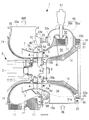
- turbocharger of one embodiment of the present invention It is a longitudinal cross-sectional view of the turbocharger of one embodiment of the present invention. It is a right view of the turbocharger of FIG. 1, and is a figure by which the bypass part and the on-off valve were abbreviate
- FIG. 1 is a longitudinal sectional view showing a turbocharger according to the present embodiment.
- the turbocharger 1 is, for example, a device that compresses combustion air of an internal combustion engine (not shown) for marine use or for power generation, and forcibly feeds high-density air into a combustion chamber of the internal combustion engine.
- the turbocharger 1 of this embodiment is provided in the internal combustion engine, and the internal combustion engine provided with the turbocharger 1 is provided in the ship.
- the turbocharger 1 is driven by the exhaust gas discharged from the internal combustion engine.
- an axial flow turbine 2 driven by exhaust gas discharged from an internal combustion engine
- a rotor shaft (rotational shaft) 3 rotationally driven by the axial flow turbine 2
- a rotor shaft 3 rotationally driven by the axial flow turbine 2
- a bearing stand (not shown) provided between the axial flow turbine 2 and the compressor and bearing-supporting the rotor shaft 3.
- the part shown by grid-like hatching in FIG. 1 is the heat insulating material 11 installed for the purpose of heat insulation and soundproofing.
- the axial flow turbine 2 includes a turbine rotor 4 driven to rotate by exhaust gas discharged from an internal combustion engine, a turbine nozzle 5 for guiding the exhaust gas to the turbine rotor 4, and an exhaust inlet casing 10.
- the turbine moving blade 4 is disposed at a downstream position close to the outlet of the turbine nozzle 5.
- a disk-shaped turbine disk 6 is disposed at one axial end of the rotor shaft 3.
- a plurality of turbine blades 4 are attached at equal intervals along the circumferential direction to the outer peripheral edge of the turbine disk 6. Then, the high temperature exhaust gas ejected from the turbine nozzle 5 passes through the turbine moving blade 4 and is expanded, whereby the turbine disk 6 and the rotor shaft 3 rotate.
- the turbine nozzle 5 is disposed on the root side (inner peripheral side) of a plurality of nozzle guide vanes 5 a annularly disposed along the circumferential direction centering on the rotor shaft 3 and the nozzle guide vanes 5 a And a ring-shaped inner peripheral member 5b joined to the root of the vane 5a. Further, the turbine nozzle 5 includes a ring-shaped outer peripheral side member 5c which is disposed on the blade end side (outer periphery side) of the nozzle guide vane 5a and joined to the blade end of the nozzle guide vane 5a.
- the turbine nozzle 5 is generally referred to as a nozzle ring, and is disposed at a close upstream position of the turbine blade 4.
- the outer peripheral side member 5c is shaped to expand in a trumpet shape from the outlet side of the exhaust gas (the downstream side of the exhaust gas flow) to the inlet side (the upstream side of the exhaust gas flow).
- a stepped portion 12 formed by bending the inner circumferential surface of the exhaust inlet casing 10 in the direction of the turbine disk 6 at an end of the outer casing 22 which is a part of the exhaust inlet casing 10 on the turbine disk 6 side. Is provided. And this level
- An exhaust gas guide cylinder 7 (exhaust gas guide portion) is connected to an end of the outlet side (downstream side of the exhaust gas flow) of the outer peripheral side member 5c.
- the connection part of the outer peripheral side member 5c and the exhaust gas guide cylinder 7 has an inlay structure in which the respective end parts are fitted.
- the exhaust gas guide cylinder 7 guides the exhaust gas having passed through the axial flow turbine 2 to the exhaust gas outlet 28 a.
- the exhaust inlet casing 10 (casing) is a member in which separate inner casing 21 and outer casing 22 are joined by a fastening portion including a bolt 23.
- the inner casing 21 and the outer casing 22 are arranged coaxially with the axial flow turbine 2.
- the outer casing 22 is disposed outside the inner casing 21.
- a space formed between the inner casing 21 and the outer casing 22 is an exhaust gas flow passage (inner circumferential side flow passage) 26 for guiding the exhaust gas to the turbine nozzle 5.
- Exhaust gas flowing from the exhaust gas inlet 10 a in a direction intersecting the axial direction of the axial flow turbine 2 (direction orthogonal to the axial direction in the example shown in FIG. 1) is led to the exhaust gas flow path 26.
- a straightening vane 61 is disposed in the exhaust gas flow path 26.
- the straightening vane 61 is for suppressing the rotational component around the axis of the turbine shaft 2 of the exhaust gas flowing into the exhaust gas flow path 26 from the exhaust gas inlet 10 a.
- the exhaust gas impinges on the straightening vane 61, whereby the rotational component of the exhaust gas around the axis of the turbine shaft 2 is suppressed, and the exhaust gas is converted into a flow along the axis.
- the straightening vane 61 is disposed at a position opposite to the exhaust gas inlet 10 a (a position 180 ° out of phase with respect to the axis of the turbine shaft 2). By providing the straightening vanes 61 at this position, the space inside the exhaust gas flow path 26 partitioned by the straightening vanes 61 becomes a laterally symmetrical space as viewed from the axial direction of the turbine shaft 2. By doing this, the exhaust gas flowing in from the exhaust gas inlet 10 a flows evenly left and right as viewed from the axial direction of the turbine shaft 2.
- the exhaust gas flow path 26 is formed over the entire circumference of the turbine rotor 4 in the rotational direction of the turbine moving blade 4 in the double structure exhaust inlet casing 10 constituted by the inner casing 21 and the outer casing 22.
- Exhaust gas introduced from the exhaust gas inlet 10 a of the exhaust inlet casing 10 as indicated by an arrow IN in FIG. 1 is led to the exhaust gas outlet 10 b through the exhaust gas flow path 26. Thereafter, the exhaust gas is discharged from the exhaust gas outlet 28a of the exhaust outlet casing 28 to the outside as shown by the arrow OUT in FIG. Further, the exhaust gas outlet 10 b is provided so as to open the exhaust gas to the turbine nozzle 5 over the entire circumference in the rotational direction of the turbine bucket 4.
- Exhaust inlet casing 10 is joined to exhaust outlet casing 28 by a plurality of bolts including bolts 60.
- the exhaust inlet casing 10 can arbitrarily set the rotational position of the axial flow turbine 2 about the axis of the axial flow turbine 2 with respect to the exhaust outlet casing 28 by attaching and detaching a plurality of bolts including the bolt 60.
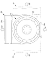
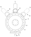
- FIG. 2 is a right side view of the turbocharger of FIG. 1, in which the bypass unit 50 and the on-off valve 51 are omitted.
- the exhaust outlet casing 28 shown by a solid line corresponds to the exhaust outlet casing shown in FIG.
- the rotational position of the exhaust outlet casing 28 with respect to the exhaust inlet casing 10 is set so that the exhaust gas inlet 10a and the exhaust gas outlet 10b are in the same direction. It can be set. Further, according to the arrangement of the exhaust outlet casing 28 shown by a solid line in FIG.
- the rotational position of the exhaust outlet casing 28 with respect to the exhaust inlet casing 10 is set so that the exhaust gas inlet 10 a and the exhaust gas outlet 10 b are orthogonal to each other. It can be set. Further, although not shown in FIG. 2, the rotational position can be set arbitrarily.
- one end (the end on the right in FIG. 1) of the inner casing 21 is fastened to the one end (the end on the right in FIG. 1) of the outer casing 22 It is fixed and supported by the unit. That is, the inner casing 21 is provided with the flange surface 21 a formed at the end on the right side in FIG. 1 opposite to the turbine disk 6. With the flange surface 22 a of the outer casing 22 superimposed on the flange surface 21 a, the inner casing 21 and the outer casing 22 are fixed by fastening with a fastening portion including the bolt 23.
- flange surfaces 21 a and 22 a are both disposed on a surface orthogonal to the axial direction of the rotor shaft 3 that rotates integrally with the turbine disk 6.
- an inner peripheral side member 5 b integrally formed with the turbine nozzle 5 is attached to an inner peripheral portion at the other end (the end on the left side in FIG. 1) of the inner casing 21 via a bolt 30.
- a first opening 22 b is provided in the inner circumferential portion of the outer casing 22 in a direction orthogonal to the axial direction of the axial flow turbine 2 (a direction orthogonal to the axial direction in the example shown in FIG. 1).
- the first opening 22 b is open to the outer peripheral surface of the outer casing 22 and is in communication with the inlet of the bypass 50 forming the bypass flow channel 52.
- the bypass flow channel 52 is a flow channel that guides the exhaust gas flowing into the exhaust gas flow channel 26 disposed on the inner circumferential side to the exhaust gas outlet 28 a without passing through the axial flow turbine 2.
- a second opening 22 c is provided in the inner peripheral portion of the outer casing 22 in a direction orthogonal to the axial direction of the axial flow turbine 2 (a direction orthogonal to the axial direction in the example shown in FIG. 1).
- the second opening 22 c is open to the outer peripheral surface of the outer casing 22 and is in communication with the outlet of the bypass 50 forming the bypass flow channel 52.
- the bypass part 50 is comprised by two members, the 1st bypass part 50a and the 2nd bypass part 50b.
- the first bypass portion 50 a is a tubular member fixed to the first opening 22 b of the outer casing 22 by a bolt or the like.
- the second bypass portion 50 b is a tubular member fixed to the second opening 22 c of the outer casing 22 by a bolt or the like.
- An on-off valve 51 for opening and closing the bypass flow passage 52 is provided between the first bypass portion 50a and the second bypass portion 50b.
- the on-off valve 51 When the on-off valve 51 is in the open state, the exhaust gas flowing into the first opening 22b circulates toward the second opening 22c.
- the open / close valve 51 When the open / close valve 51 is closed, the exhaust gas flowing into the first opening 22b is shut off so as not to flow toward the second opening 22c.
- the on-off valve 51 shall be controlled by a control part (not shown) so that it will be in an open state or any one state of a closed state
- the control unit may control so as to be in either an open state or a closed state in a plurality of stages having different degrees of opening.
- the open state is set to a small open state
- the control unit (not shown) may perform control.
- FIG. 1 shows that the bypass portion 50 and the on-off valve 51 are provided at a position facing the exhaust gas inlet 10a (180-degree rotational position around the axis of the axial flow turbine 2), but at other rotational positions It is also good.
- FIG. 3 is a right side view of the turbocharger of FIG.
- the bypass unit 50 and the on-off valve 51 shown by solid lines in FIG. 3 are disposed at the same positions as those shown in FIG. 1.
- the bypass part 50 and the on-off valve 51 which are shown by broken lines in FIG. 3 are arranged at positions different from those shown in FIG.
- the bypass portion 50 and the on-off valve 51 may be provided at any rotational position around the axis of the axial flow turbine 2.
- the rotational position of the axial flow turbine 2 about the axis of the axial flow turbine 2 with respect to the exhaust gas inlet 10 a of the bypass unit 50 and the on-off valve 51 is determined when manufacturing the outer casing 22, but the turbocharger 1 is installed It is desirable to decide according to the environment etc. of the installation place in the ship. Further, as described with reference to FIG. 2, the rotational position of the exhaust outlet casing 28 relative to the exhaust inlet casing 10 can be arbitrarily adjusted by attaching and detaching bolts. Therefore, the position of the exhaust gas inlet 10a, the positions of the bypass portion 50 and the on-off valve 51, and the position of the exhaust gas outlet 28a can be selected according to the environment of the installation place in the ship where the turbocharger 1 is installed. It is possible to set to Thereby, the appropriate turbocharger 1 can be provided according to the environment etc. of the installation place in the ship.
- the second opening 22 c of the outer casing 22 communicates with the exhaust gas flow passage 32 (the outer circumferential side flow passage) for guiding the exhaust gas flowing in from the second opening 22 c to the exhaust gas guiding cylinder 7 (exhaust gas guiding portion).
- the exhaust gas passage 32 is disposed on the outer peripheral side with respect to the exhaust gas passage 26 (inner side passage).
- the exhaust gas flow passage 32 has an other end surface 22d forming the other end (the end on the left side in FIG. 1) of the outer casing 22 and an outer peripheral surface located radially outward (outer peripheral side) of the outer peripheral side member 5c; It is a space formed by the one surface 7a which forms a recess (dent) at one end (the end on the right side in FIG. 1) of the exhaust gas guide cylinder 7 facing the other end face 22d.
- the exhaust gas flow path 32 and the space S1 formed on the radially outer side (outer peripheral side) of the exhaust gas guide cylinder 7 in the exhaust outlet casing 28 have one surface 7a and the other surface 7b opposite to the one surface 7a. It communicates via the through hole 48 penetrating in the thickness direction. Therefore, the bypass flow passage 52 and the space S1 are in communication via the exhaust gas flow passage 32 and the through hole 48.
- the on-off valve 51 is fully closed in accordance with an instruction from the control unit (not shown). In this case, the entire amount of exhaust gas discharged from the internal combustion engine flows into the axial flow turbine 2 via the exhaust gas flow passage 26 on the inner peripheral side.
- the exhaust gas led to the exhaust gas outlet 10 b of the exhaust inlet casing 10 is led to the turbine nozzle 5 from the exhaust gas outlet 10 b of the exhaust inlet casing 10.
- Exhaust gas is discharged from the downstream side of the turbine nozzle 5 after passing through the turbine nozzle 5 and is led to the entire turbine blade 4.
- the exhaust gas thus introduced to the entire turbine moving blade 4 expands as it passes through the turbine moving blade 4 and rotates the turbine disk 6 and the rotor shaft 3.
- the on-off valve 51 is fully opened in accordance with an instruction from the control unit (not shown).
- a part (for example, 4% to 20% of the total amount of exhaust gas) of the exhaust gas discharged from the internal combustion engine flows into the bypass passage 52, and the remaining exhaust gas (for example, 96% to 80% of the total amount ) Is led to the exhaust gas outlet 10 b of the exhaust inlet casing 10 through the exhaust gas flow path 26.
- the control unit when the on-off valve 51 is controlled by the control unit (not shown) so that the on-off valve 51 is in one of the open state and the closed state in multiple stages with different degrees of opening. It is preferable to control the degree appropriately in accordance with various conditions so as to suppress the deterioration of the fuel efficiency of the internal combustion engine. For example, according to the intake air temperature of the compressor (not shown) of the turbocharger 1 or the load of the internal combustion engine, the control unit varies the opening degree of the on-off valve 51 with the necessary minimum. preferable. By doing this, it is possible to prevent rapid fluctuations in the flow rate of the combustion air that cause deterioration of the fuel efficiency of the internal combustion engine.
- the exhaust gas led to the bypass flow passage 52 is led to the space S1 through the exhaust gas flow passage 32 and the through hole 48, and together with the exhaust gas passing through the turbine rotor blade 4, the exhaust gas outlet of the exhaust outlet casing 28 It is discharged from 28a to the outside. Then, when the exhaust gas passes through the turbine moving blades 4, the compressor provided at the other end of the rotor shaft 3 is driven by rotating the turbine disk 6 and the rotor shaft 3 to drive the internal combustion engine. The air supplied is compressed.
- the turbocharger 1 of the present embodiment is configured such that the exhaust gas flowing in from the exhaust gas inlet 10 a is formed by the exhaust gas flow path 26 (inner peripheral side flow path) formed by the inner casing 21 and the outer casing 22. Leads to the axial flow turbine 2.
- the exhaust gas having passed through the axial flow turbine 2 is guided by the exhaust gas guide cylinder 7 to the exhaust gas outlet 28 a. Further, the exhaust gas flowing into the exhaust gas flow path 26 (inner peripheral side flow path) along the direction intersecting the axial direction of the axial flow turbine 2 is bypassed through the first opening 22 b of the outer casing 22. It flows into the 52 entrance.
- first opening 22 b Since the first opening 22 b is open in the direction intersecting the axial direction of the axial flow turbine 2, exhaust gas having a velocity component in the direction intersecting the axial direction of the axial flow turbine 2 is the first opening 22 b Flows into the inlet portion of the bypass flow channel 52 from the The exhaust gas flowing in from the first opening 22b flows into the exhaust gas flow path 32 (outer peripheral side flow path) from the second opening 22c, merges with the exhaust gas passing through the axial flow turbine 2, and is discharged to the exhaust gas outlet 28a Led.
- bypass flow passage 52 is a passage connecting the first opening 22 b and the second opening 22 c provided in the outer casing 22, when the bypass flow passage 52 is closed by the on-off valve 51, the downstream side of the on-off valve 51 Exhaust gas is not led to the axial flow turbine 2. Therefore, the exhaust gas downstream of the on-off valve 51 does not adversely affect the performance of the turbocharger 1. Further, the exhaust gas on the upstream side of the on-off valve 51 is pushed into the first opening 22 b by the exhaust gas which is going to flow from the first opening 22 b into the inlet of the bypass flow passage 52. Therefore, the exhaust gas on the upstream side of the on-off valve 51 does not adversely affect the performance of the turbocharger 1.
- the inner casing 21 is not a special structure for guiding the exhaust gas to the bypass flow passage 52, and together with the outer casing 22, the exhaust gas flow passage 26 for guiding the exhaust gas to the axial flow turbine 2 (A flow path) is formed.
- the turbocharger 1 of the present embodiment it is possible to suppress the performance decrease when the on-off valve 51 is closed, and to suppress the design man-hour and the manufacturing cost of the inner casing 21.
- the inner casing 21 and the outer casing 22 are respectively joined to the exhaust outlet casing 28 by a plurality of bolts, and the inner casing 21 and the outer casing 22 attach and detach a plurality of bolts.
- the rotational position of the axial flow turbine 2 about the axis of the axial flow turbine 2 relative to the exhaust gas guide cylinder 7 can be arbitrarily set.
- the exhaust gas inlet 10a provided in the inner casing 21 and the outer casing 22 and the exhaust gas outlet 28a provided in the exhaust outlet casing 28 can be used according to the environment in which the turbocharger 1 is installed. It can be installed at any rotational position.
- the on-off valve 51 is opened, and a part of the exhaust gas is diverted from the exhaust gas passage 26 to the bypass passage 52, and the on-off valve 51 is opened. And a step of flowing the entire amount of exhaust gas from the exhaust gas passage 26 into the axial flow turbine 2 without diverting the exhaust gas from the exhaust gas passage 26 to the bypass passage 52 in a state. By doing this, it is possible to appropriately switch whether or not to bypass a part of the exhaust gas to the bypass flow passage 52 and operate the turbocharger 1.
- the axial flow turbine has been described.
- the present invention is also applicable to a centrifugal / slant flow turbine and a rotating machine such as a power turbine.
Abstract
Description
また、バイパス管L2を引き回すのに必要なスペースを確保できたとしても、機関室内においてバイパス管L2を引き回す大掛かりな配管工事を行わなければならず、コスト的に見合わないといった問題点があった。 Therefore, the exhaust gas bypass system can not be applied to a ship that can not secure a space necessary to draw the bypass pipe L2 because the bypass pipe L2 has to be routed around the engine room with limited space. There was a problem.
In addition, even if the space required to draw the bypass pipe L2 can be secured, a large-scale piping work must be performed to draw the bypass pipe L2 in the engine room, and there is a problem that the cost is not sufficient. .
そのため、開閉弁を閉じて排気ガスのバイパスを行わないようにしても、バイパス室32から排気ガスが流出し、ターボ過給機1の性能への悪影響が生じる可能性があるという問題があった。具体的には、内側ケーシング内の排気ガスの一部が、内側ケーシングと外側ケーシングとの間の隙間からバイパス室32へ流入してタービン動翼を通過せずに外部に流出し、タービン動翼の駆動に用いられる排気ガスの流量が減少するという問題があった。さらに、特許文献2の内側ケーシングは、バイパス室32を形成するための特殊な構造とする必要があり、内側ケーシングの設計工数がかかり、製造コストが増大するという問題もあった。 However, an inner peripheral side flow passage for guiding the exhaust gas to the axial flow turbine is provided between the inner casing and the outer casing, and the
Therefore, even if the on-off valve is closed and the exhaust gas is not bypassed, the exhaust gas may flow out of the
本発明に係るタービンは、内燃機関から排出された排気ガスにより駆動するタービンであって、タービン動翼と、前記排気ガスの流路を形成するケーシングと、前記ケーシングの外周に設けられ、前記排気ガスを、前記タービン動翼を通過させずに、排気ガス出口に導くためのバイパス流路を形成するバイパス部と、前記バイパス流路を開閉する開閉弁と、を備えることを特徴とする。 The present invention adopts the following means in order to solve the above problems.
A turbine according to the present invention is a turbine driven by exhaust gas discharged from an internal combustion engine, and is provided on a turbine blade, a casing forming a flow path of the exhaust gas, and an outer periphery of the casing. It is characterized by comprising a bypass portion forming a bypass flow passage for introducing gas to the exhaust gas outlet without passing the turbine rotor blade, and an open / close valve opening / closing the bypass flow passage.
このように、本発明に係るタービンによれば、開閉弁を閉じた際の性能低下を抑えるとともに、ケーシングの設計工数及び製造コストを抑えることが可能となる。 In the turbine according to the present invention, a bypass flow passage is formed by a bypass portion provided on an outer periphery of a casing forming a flow passage of exhaust gas discharged from an internal combustion engine. The bypass flow channel is a flow channel that guides the exhaust gas to the exhaust gas outlet without passing the turbine blades, and an open / close valve is provided in the flow channel. When the bypass flow passage is closed by the on-off valve, the exhaust gas is not led to the exhaust gas outlet without passing through the turbine blades, so the performance of the turbine is not adversely affected.
As described above, according to the turbine according to the present invention, it is possible to suppress the performance decrease when the on-off valve is closed, and to suppress the design man-hour and the manufacturing cost of the casing.
このように、本発明に係るターボ過給機によれば、開閉弁を閉じた際の性能低下を抑えるとともに、内側ケーシングの設計工数及び製造コストを抑えることができる。 The bypass flow path connects the first opening and the second opening provided in the outer casing with the on-off valve interposed therebetween, and the gas flowing in from the exhaust gas inlet passes through the
As described above, according to the turbocharger according to the present invention, it is possible to suppress the performance decrease when the on-off valve is closed, and to reduce the number of design steps and the manufacturing cost of the inner casing.
このようにすることで、内側ケーシング及び外側ケーシングに設けられた排気ガス入口と排気出口ケーシングに設けられた排気ガス出口とを、ターボ過給機が設置される環境に応じた任意の回転位置に設置することができる。 In the turbocharger according to the first aspect of the present invention, the inner casing and the outer casing are respectively joined to an exhaust outlet casing forming the exhaust gas outlet by a plurality of bolts, and the inner casing and the outer The casing may be configured such that a rotational position of the turbine blade about the rotation axis with respect to the exhaust gas guide portion can be arbitrarily installed by attaching and detaching the plurality of bolts.
By doing this, the exhaust gas inlet provided to the inner casing and the outer casing and the exhaust gas outlet provided to the exhaust outlet casing can be placed at any rotational position according to the environment where the turbocharger is installed. It can be installed.
また、本発明に係る内燃機関は、上記のターボ過給機を備えている。
また、本発明に係る船舶は、上記の内燃機関を備えている。 A turbocharger according to the present invention includes any one of the above turbines.
In addition, an internal combustion engine according to the present invention includes the above-described turbocharger.
Further, a ship according to the present invention includes the internal combustion engine described above.
図1は本実施形態のターボ過給機を示す縦断面図である。 Hereinafter, a turbocharger according to an embodiment of the present invention will be described with reference to FIG.
FIG. 1 is a longitudinal sectional view showing a turbocharger according to the present embodiment.
なお、図1中に格子状のハッチングで示す部分は、断熱および防音の目的で設置された断熱材11である。 The
In addition, the part shown by grid-like hatching in FIG. 1 is the
図2において、実線で示される排気出口ケーシング28は図1に示す排気出口ケーシングに対応している。図1及び図2において実線で示す排気出口ケーシング28の配置によれば、排気ガス入口10aと排気ガス出口10bとが同一方向となるように、排気入口ケーシング10に対する排気出口ケーシング28の回転位置を設定することができる。また、図2において実線で示す排気出口ケーシング28の配置によれば、排気ガス入口10aと排気ガス出口10bとが直交する方向となるように、排気入口ケーシング10に対する排気出口ケーシング28の回転位置を設定することができる。また、図2には示されていないが、回転位置は任意に設定可能である。 FIG. 2 is a right side view of the turbocharger of FIG. 1, in which the
In FIG. 2, the exhaust outlet casing 28 shown by a solid line corresponds to the exhaust outlet casing shown in FIG. According to the arrangement of the exhaust outlet casing 28 shown by solid lines in FIGS. 1 and 2, the rotational position of the exhaust outlet casing 28 with respect to the exhaust inlet casing 10 is set so that the
一方、内側ケーシング21の他端部(図1において左側の端部)における内周部には、タービンノズル5と一体成形された内周側部材5bがボルト30を介して取り付けられている。 In the double-structured exhaust inlet casing 10 described above, one end (the end on the right in FIG. 1) of the
On the other hand, an inner
図3は、図1のターボ過給機の右側面図である。図3において実線で示すバイパス部50及び開閉弁51は、図1に示すものと同位置に配置されている。一方、図3において破線で示すバイパス部50及び開閉弁51は、図1に示すものとは異なる位置に配置されている。その他、バイパス部50及び開閉弁51は軸流タービン2の軸周りの任意の回転位置に設けてもよい。 FIG. 1 shows that the
FIG. 3 is a right side view of the turbocharger of FIG. The
内燃機関の負荷が低く、内燃機関から排出される排気ガスの量が少ない場合、制御部(不図示)からの指示により開閉弁51は全閉状態となる。この場合、内燃機関から排出される排気ガスの全量が内周側の排気ガス流路26を介して軸流タービン2に流れ込む。 Next, the flow of the exhaust gas in the
When the load on the internal combustion engine is low and the amount of exhaust gas discharged from the internal combustion engine is small, the on-off
このように、本実施形態のターボ過給機1によれば、開閉弁51を閉じた際の性能低下を抑えるとともに、内側ケーシング21の設計工数及び製造コストを抑えることができる。 Since the
As described above, according to the
このようにすることで、内側ケーシング21及び外側ケーシング22に設けられた排気ガス入口10aと排気出口ケーシング28に設けられた排気ガス出口28aとを、ターボ過給機1が設置される環境に応じた任意の回転位置に設置することができる。 In the
By doing this, the
2 軸流タービン
3 ロータ軸
4 タービン動翼
5 タービンノズル
7 排気ガス案内筒(排気ガス案内部)
10 排気入口ケーシング(ケーシング)
10a 排気ガス入口
10b 排気ガス出口
21 内側ケーシング
22 外側ケーシング
22b 第1開口部
22c 第2開口部
26 排気ガス流路(内周側流路)
28 排気出口ケーシング
30,60 ボルト
32 排気ガス流路(外周側流路)
48 貫通穴
50 バイパス部
51 開閉弁
52 バイパス流路
10 Exhaust inlet casing (casing)
10a
28
48 through
Claims (6)
- 内燃機関から排出された排気ガスにより駆動するタービンであって、
タービン動翼と、
前記排気ガスの流路を形成するケーシングと、
前記ケーシングの外周に設けられ、前記排気ガスを、前記タービン動翼を通過させずに、排気ガス出口に導くためのバイパス流路を形成するバイパス部と、
前記バイパス流路を開閉する開閉弁と、
を備えることを特徴とするタービン。 A turbine driven by exhaust gas discharged from an internal combustion engine, comprising:
Turbine blades,
A casing forming a flow path of the exhaust gas;
A bypass portion provided on an outer periphery of the casing and forming a bypass flow passage for guiding the exhaust gas to an exhaust gas outlet without passing the turbine blade;
An on-off valve for opening and closing the bypass flow path;
A turbine characterized by comprising: - 前記ケーシングは、
前記タービン動翼の回転軸と同軸に配置される内側ケーシングと、
前記内側ケーシングの外側に配置され、排気ガス入口から前記タービン動翼の回転軸方向に交差する方向に流入する前記排気ガスを前記タービン動翼に導く内周側流路を、前記内側ケーシングとともに形成する外側ケーシングと、を備え、
前記外側ケーシングは、
前記回転軸方向に交差する方向に開口し、前記バイパス流路の入口部に連通する第1開口部と、
前記回転軸方向に交差する方向に開口し、前記バイパス流路の出口部に連通する第2開口部と、
前記内周側流路よりも外周側に配置され、前記第2開口部から流入する前記排気ガスを前記排気ガス出口へ導く外周側流路と、を有することを特徴とする請求項1に記載のタービン。 The casing is
An inner casing coaxially arranged with the rotational axis of the turbine blade;
An inner circumferential side flow path, which is disposed outside the inner casing and guides the exhaust gas flowing from the exhaust gas inlet in a direction intersecting the rotational axis direction of the turbine bucket, to the turbine bucket is formed with the inner casing. And an outer casing
The outer casing is
A first opening that opens in a direction that intersects the rotation axis direction and that communicates with the inlet of the bypass flow path;
A second opening that opens in a direction intersecting the rotation axis direction and communicates with the outlet of the bypass flow path;
The outer peripheral side flow path which is arranged on the outer peripheral side than the inner peripheral side flow path and which guides the exhaust gas flowing in from the second opening to the exhaust gas outlet. Turbines. - 前記内側ケーシング及び前記外側ケーシングは、前記排気ガス出口を形成する排気出口ケーシングにそれぞれ複数のボルトにより接合されており、
前記内側ケーシング及び前記外側ケーシングは、前記複数のボルトを着脱することにより、前記タービン動翼の前記回転軸周りの前記排気出口ケーシングに対する回転位置を任意に設置可能であることを特徴とする請求項2に記載のタービン。 The inner casing and the outer casing are respectively joined by a plurality of bolts to an exhaust outlet casing forming the exhaust gas outlet,
The inner casing and the outer casing can be installed at any rotational position relative to the exhaust outlet casing around the rotation axis of the turbine blade by attaching and detaching the plurality of bolts. The turbine according to 2. - 請求項1から請求項3のいずれかに記載のタービンを備えることを特徴とするターボ過給機。 A turbocharger comprising the turbine according to any one of claims 1 to 3.
- 請求項4に記載のターボ過給機を備えることを特徴とする内燃機関。 An internal combustion engine comprising the turbocharger according to claim 4.
- 請求項5に記載の内燃機関を備えることを特徴とする船舶。 A ship comprising the internal combustion engine according to claim 5.
Priority Applications (3)
| Application Number | Priority Date | Filing Date | Title |
|---|---|---|---|
| CN201480038588.8A CN105492738B (en) | 2013-09-05 | 2014-08-27 | Turbine, turbocharger, internal combustion engine and ship |
| EP14842587.9A EP3006694B1 (en) | 2013-09-05 | 2014-08-27 | Turbine, turbocharger, internal combustion engine, and ship |
| KR1020167000287A KR101834672B1 (en) | 2013-09-05 | 2014-08-27 | Turbine, turbocharger, internal combustion engine, and ship |
Applications Claiming Priority (2)
| Application Number | Priority Date | Filing Date | Title |
|---|---|---|---|
| JP2013184411A JP6165564B2 (en) | 2013-09-05 | 2013-09-05 | Axial turbine, turbocharger, internal combustion engine, and ship |
| JP2013-184411 | 2013-09-05 |
Publications (1)
| Publication Number | Publication Date |
|---|---|
| WO2015033844A1 true WO2015033844A1 (en) | 2015-03-12 |
Family
ID=52628319
Family Applications (1)
| Application Number | Title | Priority Date | Filing Date |
|---|---|---|---|
| PCT/JP2014/072502 WO2015033844A1 (en) | 2013-09-05 | 2014-08-27 | Turbine, turbocharger, internal combustion engine, and ship |
Country Status (5)
| Country | Link |
|---|---|
| EP (1) | EP3006694B1 (en) |
| JP (1) | JP6165564B2 (en) |
| KR (1) | KR101834672B1 (en) |
| CN (1) | CN105492738B (en) |
| WO (1) | WO2015033844A1 (en) |
Citations (4)
| Publication number | Priority date | Publication date | Assignee | Title |
|---|---|---|---|---|
| JPH11324691A (en) * | 1998-05-12 | 1999-11-26 | Mitsubishi Heavy Ind Ltd | Discharge device for leaked gas from exhaust gas turbine supercharger |
| JP2010216468A (en) * | 2009-02-18 | 2010-09-30 | Mitsubishi Heavy Ind Ltd | Turbo supercharger |
| JP2011149327A (en) | 2010-01-21 | 2011-08-04 | Mitsubishi Heavy Ind Ltd | Engine exhaust energy recovery device, and ship and power generation plant with the same |
| JP2013124626A (en) | 2011-12-15 | 2013-06-24 | Mitsubishi Heavy Ind Ltd | Exhaust gas inlet casing of turbocharger |
Family Cites Families (10)
| Publication number | Priority date | Publication date | Assignee | Title |
|---|---|---|---|---|
| JPS5520617U (en) * | 1978-07-25 | 1980-02-08 | ||
| JPS56163625U (en) * | 1980-05-06 | 1981-12-04 | ||
| GB8406860D0 (en) * | 1984-03-16 | 1984-04-18 | Holset Engineering Co | Wastegate valve |
| JPH07119476A (en) * | 1993-10-26 | 1995-05-09 | Aisin Seiki Co Ltd | Waste gate structure of turbocharger |
| JPH08232671A (en) * | 1994-12-28 | 1996-09-10 | Aisin Seiki Co Ltd | Waste gate structure for turbocharger |
| JP4231510B2 (en) * | 2006-05-11 | 2009-03-04 | トヨタ自動車株式会社 | Internal combustion engine |
| JP2009287434A (en) * | 2008-05-28 | 2009-12-10 | Toyota Motor Corp | Exhaust recirculation device for internal combustion engine |
| JP4956675B2 (en) * | 2008-11-19 | 2012-06-20 | 株式会社小松製作所 | Slide nozzle type variable turbocharger |
| JP5223898B2 (en) * | 2010-09-09 | 2013-06-26 | 株式会社デンソー | Exhaust control device for internal combustion engine |
| JP5246284B2 (en) * | 2011-03-02 | 2013-07-24 | トヨタ自動車株式会社 | Control device for internal combustion engine |
-
2013
- 2013-09-05 JP JP2013184411A patent/JP6165564B2/en active Active
-
2014
- 2014-08-27 WO PCT/JP2014/072502 patent/WO2015033844A1/en active Application Filing
- 2014-08-27 CN CN201480038588.8A patent/CN105492738B/en active Active
- 2014-08-27 EP EP14842587.9A patent/EP3006694B1/en active Active
- 2014-08-27 KR KR1020167000287A patent/KR101834672B1/en active IP Right Grant
Patent Citations (4)
| Publication number | Priority date | Publication date | Assignee | Title |
|---|---|---|---|---|
| JPH11324691A (en) * | 1998-05-12 | 1999-11-26 | Mitsubishi Heavy Ind Ltd | Discharge device for leaked gas from exhaust gas turbine supercharger |
| JP2010216468A (en) * | 2009-02-18 | 2010-09-30 | Mitsubishi Heavy Ind Ltd | Turbo supercharger |
| JP2011149327A (en) | 2010-01-21 | 2011-08-04 | Mitsubishi Heavy Ind Ltd | Engine exhaust energy recovery device, and ship and power generation plant with the same |
| JP2013124626A (en) | 2011-12-15 | 2013-06-24 | Mitsubishi Heavy Ind Ltd | Exhaust gas inlet casing of turbocharger |
Also Published As
| Publication number | Publication date |
|---|---|
| JP6165564B2 (en) | 2017-07-19 |
| EP3006694A4 (en) | 2016-07-27 |
| KR20160013248A (en) | 2016-02-03 |
| CN105492738B (en) | 2019-04-09 |
| EP3006694A1 (en) | 2016-04-13 |
| KR101834672B1 (en) | 2018-03-05 |
| EP3006694B1 (en) | 2018-11-28 |
| JP2015052276A (en) | 2015-03-19 |
| CN105492738A (en) | 2016-04-13 |
Similar Documents
| Publication | Publication Date | Title |
|---|---|---|
| KR101370117B1 (en) | Turbo supercharger | |
| US9932843B2 (en) | Double flow turbine housing turbocharger | |
| US20230148411A1 (en) | Power assisted engine start bleed system | |
| US20080298953A1 (en) | Wastegate assembly | |
| US8567190B2 (en) | Air supplier, particularly for an air supply system for fuel cells | |
| RU2494287C2 (en) | Gas turbine engine air manifold | |
| EP3301277B1 (en) | Turbocharger with ported turbine shroud | |
| CA2653904A1 (en) | Axial flow fluid device | |
| WO2013089158A1 (en) | Turbocharger exhaust entrance casing | |
| KR101529411B1 (en) | Turbocharger | |
| JP5804756B2 (en) | Supercharger system, internal combustion engine, and supercharger system control method | |
| WO2015033844A1 (en) | Turbine, turbocharger, internal combustion engine, and ship | |
| CN111794860A (en) | Turbine engine for an aircraft | |
| KR102632033B1 (en) | Supercharger casing and supercharger provided therewith | |
| EP2873830A1 (en) | Turbocharger, turbine nozzle, and ship | |
| JP5402078B2 (en) | Supercharger | |
| JP2016156358A (en) | Turbine and turbo super charger |
Legal Events
| Date | Code | Title | Description |
|---|---|---|---|
| WWE | Wipo information: entry into national phase |
Ref document number: 201480038588.8 Country of ref document: CN |
|
| 121 | Ep: the epo has been informed by wipo that ep was designated in this application |
Ref document number: 14842587 Country of ref document: EP Kind code of ref document: A1 |
|
| WWE | Wipo information: entry into national phase |
Ref document number: 2014842587 Country of ref document: EP |
|
| ENP | Entry into the national phase |
Ref document number: 20167000287 Country of ref document: KR Kind code of ref document: A |
|
| NENP | Non-entry into the national phase |
Ref country code: DE |