EP2711518A2 - Abgasanlage für ein Kraftfahrzeug - Google Patents
Abgasanlage für ein Kraftfahrzeug Download PDFInfo
- Publication number
- EP2711518A2 EP2711518A2 EP13184763.4A EP13184763A EP2711518A2 EP 2711518 A2 EP2711518 A2 EP 2711518A2 EP 13184763 A EP13184763 A EP 13184763A EP 2711518 A2 EP2711518 A2 EP 2711518A2
- Authority
- EP
- European Patent Office
- Prior art keywords
- reducing agent
- exhaust gas
- exhaust system
- gas purification
- purification device
- Prior art date
- Legal status (The legal status is an assumption and is not a legal conclusion. Google has not performed a legal analysis and makes no representation as to the accuracy of the status listed.)
- Granted
Links
Images


Classifications
-
- F—MECHANICAL ENGINEERING; LIGHTING; HEATING; WEAPONS; BLASTING
- F01—MACHINES OR ENGINES IN GENERAL; ENGINE PLANTS IN GENERAL; STEAM ENGINES
- F01N—GAS-FLOW SILENCERS OR EXHAUST APPARATUS FOR MACHINES OR ENGINES IN GENERAL; GAS-FLOW SILENCERS OR EXHAUST APPARATUS FOR INTERNAL-COMBUSTION ENGINES
- F01N3/00—Exhaust or silencing apparatus having means for purifying, rendering innocuous, or otherwise treating exhaust
- F01N3/08—Exhaust or silencing apparatus having means for purifying, rendering innocuous, or otherwise treating exhaust for rendering innocuous
- F01N3/10—Exhaust or silencing apparatus having means for purifying, rendering innocuous, or otherwise treating exhaust for rendering innocuous by thermal or catalytic conversion of noxious components of exhaust
- F01N3/18—Exhaust or silencing apparatus having means for purifying, rendering innocuous, or otherwise treating exhaust for rendering innocuous by thermal or catalytic conversion of noxious components of exhaust characterised by methods of operation; Control
- F01N3/20—Exhaust or silencing apparatus having means for purifying, rendering innocuous, or otherwise treating exhaust for rendering innocuous by thermal or catalytic conversion of noxious components of exhaust characterised by methods of operation; Control specially adapted for catalytic conversion
- F01N3/206—Adding periodically or continuously substances to exhaust gases for promoting purification, e.g. catalytic material in liquid form, NOx reducing agents
- F01N3/2066—Selective catalytic reduction [SCR]
-
- F—MECHANICAL ENGINEERING; LIGHTING; HEATING; WEAPONS; BLASTING
- F01—MACHINES OR ENGINES IN GENERAL; ENGINE PLANTS IN GENERAL; STEAM ENGINES
- F01N—GAS-FLOW SILENCERS OR EXHAUST APPARATUS FOR MACHINES OR ENGINES IN GENERAL; GAS-FLOW SILENCERS OR EXHAUST APPARATUS FOR INTERNAL-COMBUSTION ENGINES
- F01N3/00—Exhaust or silencing apparatus having means for purifying, rendering innocuous, or otherwise treating exhaust
- F01N3/08—Exhaust or silencing apparatus having means for purifying, rendering innocuous, or otherwise treating exhaust for rendering innocuous
- F01N3/10—Exhaust or silencing apparatus having means for purifying, rendering innocuous, or otherwise treating exhaust for rendering innocuous by thermal or catalytic conversion of noxious components of exhaust
- F01N3/24—Exhaust or silencing apparatus having means for purifying, rendering innocuous, or otherwise treating exhaust for rendering innocuous by thermal or catalytic conversion of noxious components of exhaust characterised by constructional aspects of converting apparatus
- F01N3/28—Construction of catalytic reactors
- F01N3/2892—Exhaust flow directors or the like, e.g. upstream of catalytic device
-
- F—MECHANICAL ENGINEERING; LIGHTING; HEATING; WEAPONS; BLASTING
- F01—MACHINES OR ENGINES IN GENERAL; ENGINE PLANTS IN GENERAL; STEAM ENGINES
- F01N—GAS-FLOW SILENCERS OR EXHAUST APPARATUS FOR MACHINES OR ENGINES IN GENERAL; GAS-FLOW SILENCERS OR EXHAUST APPARATUS FOR INTERNAL-COMBUSTION ENGINES
- F01N2240/00—Combination or association of two or more different exhaust treating devices, or of at least one such device with an auxiliary device, not covered by indexing codes F01N2230/00 or F01N2250/00, one of the devices being
- F01N2240/20—Combination or association of two or more different exhaust treating devices, or of at least one such device with an auxiliary device, not covered by indexing codes F01N2230/00 or F01N2250/00, one of the devices being a flow director or deflector
-
- F—MECHANICAL ENGINEERING; LIGHTING; HEATING; WEAPONS; BLASTING
- F01—MACHINES OR ENGINES IN GENERAL; ENGINE PLANTS IN GENERAL; STEAM ENGINES
- F01N—GAS-FLOW SILENCERS OR EXHAUST APPARATUS FOR MACHINES OR ENGINES IN GENERAL; GAS-FLOW SILENCERS OR EXHAUST APPARATUS FOR INTERNAL-COMBUSTION ENGINES
- F01N2610/00—Adding substances to exhaust gases
- F01N2610/02—Adding substances to exhaust gases the substance being ammonia or urea
-
- F—MECHANICAL ENGINEERING; LIGHTING; HEATING; WEAPONS; BLASTING
- F01—MACHINES OR ENGINES IN GENERAL; ENGINE PLANTS IN GENERAL; STEAM ENGINES
- F01N—GAS-FLOW SILENCERS OR EXHAUST APPARATUS FOR MACHINES OR ENGINES IN GENERAL; GAS-FLOW SILENCERS OR EXHAUST APPARATUS FOR INTERNAL-COMBUSTION ENGINES
- F01N2610/00—Adding substances to exhaust gases
- F01N2610/10—Adding substances to exhaust gases the substance being heated, e.g. by heating tank or supply line of the added substance
- F01N2610/102—Adding substances to exhaust gases the substance being heated, e.g. by heating tank or supply line of the added substance after addition to exhaust gases, e.g. by a passively or actively heated surface in the exhaust conduit
-
- Y—GENERAL TAGGING OF NEW TECHNOLOGICAL DEVELOPMENTS; GENERAL TAGGING OF CROSS-SECTIONAL TECHNOLOGIES SPANNING OVER SEVERAL SECTIONS OF THE IPC; TECHNICAL SUBJECTS COVERED BY FORMER USPC CROSS-REFERENCE ART COLLECTIONS [XRACs] AND DIGESTS
- Y02—TECHNOLOGIES OR APPLICATIONS FOR MITIGATION OR ADAPTATION AGAINST CLIMATE CHANGE
- Y02A—TECHNOLOGIES FOR ADAPTATION TO CLIMATE CHANGE
- Y02A50/00—TECHNOLOGIES FOR ADAPTATION TO CLIMATE CHANGE in human health protection, e.g. against extreme weather
- Y02A50/20—Air quality improvement or preservation, e.g. vehicle emission control or emission reduction by using catalytic converters
-
- Y—GENERAL TAGGING OF NEW TECHNOLOGICAL DEVELOPMENTS; GENERAL TAGGING OF CROSS-SECTIONAL TECHNOLOGIES SPANNING OVER SEVERAL SECTIONS OF THE IPC; TECHNICAL SUBJECTS COVERED BY FORMER USPC CROSS-REFERENCE ART COLLECTIONS [XRACs] AND DIGESTS
- Y02—TECHNOLOGIES OR APPLICATIONS FOR MITIGATION OR ADAPTATION AGAINST CLIMATE CHANGE
- Y02T—CLIMATE CHANGE MITIGATION TECHNOLOGIES RELATED TO TRANSPORTATION
- Y02T10/00—Road transport of goods or passengers
- Y02T10/10—Internal combustion engine [ICE] based vehicles
- Y02T10/12—Improving ICE efficiencies
Definitions
- the present invention relates to an exhaust system for a motor vehicle and a motor vehicle with such an exhaust system.
- the exhaust gases operatively generated in an internal combustion engine of a motor vehicle can be cleaned with the aid of a vehicle catalytic converter in order to significantly reduce the pollutant emission of the exhaust gas.
- Such cleaning of the exhaust gas can be done by adding a reducing agent to the exhaust gas of the internal combustion engine in an exhaust gas treatment device.
- a reducing agent to the exhaust gas of the internal combustion engine in an exhaust gas treatment device.
- One known method based on such addition of a reducing agent to the exhaust gas is so-called Selective Catalytic Reduction ("SCR”), in which nitrogen oxide compounds in the exhaust gas are chemically reduced.
- Such a selective catalytic reduction is particularly useful in connection with internal combustion engines, which generate a high excess of air in the combustion of fuel, as is the case for example in diesel engines, in whose exhaust high oxygen concentrations are present. Due to such a high oxygen concentration in the exhaust gas, the use of a conventional three-way catalyst for the reduction of nitrogen oxides is not possible. Therefore, in conjunction with diesel engines, oxidation catalysts are often used which reduce the emission of CO and C m H n .
- the catalytically active noble metals such as platinum or palladium can be stored in a so-called "washcoat".
- the actual selective catalytic reduction takes place in a region of the exhaust gas treatment device connected downstream of the diesel oxidation catalytic converter.
- a reducing agent ammonia can be used, which is the Exhaust treatment device must be provided.
- ammonia is not injected directly into the exhaust system, but introduced in the form of a reducing agent precursor in the exhaust system.
- a precursor can be, for example, a urea-water solution known commercially as "Adblue".
- the conversion of such a precursor to the actual reducing agent (ammonia) can take place thermally and / or with the aid of a catalyst within an exhaust gas stream in the region of the internal combustion engine downstream of the exhaust gas treatment device.
- the supply of the reducing agent in the exhaust system can be done for example by injection by means of an injector.
- an injector may be located downstream of the actual diesel oxidation catalyst.
- droplets of the urea-water solution can hit the surface of the diesel oxidation catalyst and form undesired deposits in such an arrangement.
- the same applies to the ammonia formed from the urea-water solution since contact of ammonia with the catalytically active noble metals of the diesel oxidation catalyst, for example in a "washcoat", lead to an undesired reaction of the ammonia with platinum or palladium to nitrogen oxides can.
- the invention is based on the general idea between the exhaust gas purification device of the exhaust system, for example a diesel oxidation catalyst "DOC", and the reducing agent supply device, for example in the form of an injector for introducing a urea-water solution into the exhaust system, a reducing agent.
- DOC diesel oxidation catalyst
- the reducing agent supply device for example in the form of an injector for introducing a urea-water solution into the exhaust system, a reducing agent.
- Provide deflection which has at least one scoop-like design reductant deflection.
- a reducing agent deflecting device By means of such a reducing agent deflecting device it can be achieved that unwanted contact between the precursor of the reducing agent, for example a urea-water solution or the reducing agent itself, for example ammonia, and the exhaust gas purification device, for example a diesel oxidation catalyst, is avoided. This applies in particular to the catalytically active noble metals in the exhaust gas purification device.
- Reducing agent and reducing agent precursor water solution can be deflected by the exhaust gas purification device by means of the at least one reducing agent deflecting element, so that it can largely or completely be prevented that the precursor or the reducing agent formed from the precursor can penetrate into the diesel oxidation catalyst.
- the exhaust system comprises an exhaust gas purification device for cleaning exhaust gas discharged from an internal combustion engine of the motor vehicle and a downstream and spaced apart from the exhaust gas purification device arranged Reducing agent supply means.
- reducing agent can be introduced into the exhaust system.
- the term "reducing agent supply means" is to be understood not only a device which introduces a reducing agent, such as ammonia, directly into the exhaust system; Rather, this term expressly also the indirect supply of the reducing agent is to be understood such that by means of the reducing agent supply means, a precursor of the reducing agent, such as a urea-water solution is introduced into the exhaust system and this precursor in the exhaust system by means of thermal reaction o .ae. reacts to the actual reducing agent.
- the reducing agent supply means may be configured and / or arranged such that a flow direction with which the reducing agent is introduced into the exhaust system, at least partially opposite to the flow direction of the exhaust gas in the exhaust system.
- the reducing agent is introduced so as to have, at least initially, a propagation direction having a directional component opposite to the exhaust gas flow direction, so that the reducing agent moves toward the upstream exhaust gas purification device.
- a time available for evaporation of the reducing agent and for mixing with the exhaust gas is increased, which improves the efficiency of the reducing agent introduction in a small space.
- the (main) flow direction of the reducing agent is inclined by 45 ° ⁇ 30 °, in particular by 45 ° ⁇ 15 °, with respect to the (main) flow direction of the exhaust gas.
- the reducing agent deflecting element may be configured such that, introduced from the reducing agent supply device into the exhaust gas system and striking the reducing agent deflecting element Reducing agent is deflected away from the exhaust gas purification device.
- the reducing agent deflecting element is designed in such a way that liquid reducing agent introduced into the exhaust gas system by the reducing agent supply device and impinging on the reducing agent deflecting element is vaporized.
- the reducing agent deflecting element can have the respective evaporator surface downstream of the exhaust gas flow, so that it is heated by the incoming exhaust gas flow, which promotes the evaporation.
- the reducing agent deflecting device is arranged and / or attached to an outlet side of the exhaust gas purification device.
- the reducing agent deflecting device can be used particularly effectively if reducing agent or a precursor thereof is introduced into the exhaust system downstream of the exhaust gas purification device by means of the reducing agent supply device and injected into the exhaust gas system against a flow direction of the exhaust gas.
- the reducing agent deflecting device may be formed as a separate component, which is mounted downstream of the exhaust gas purification device in the exhaust line; However, in a particularly easy to manufacture embodiment, the reducing agent deflecting device can also be attached directly to the outlet side of the exhaust gas purification device, for example by means of welding or the like.
- the reducing agent deflecting device can comprise not only a single reducing agent deflecting element but a plurality of such reducing agent deflecting elements, all of which are arranged in the region of the outlet side of the exhaust gas purification device are.
- a particularly high cross-section of the reducing agent deflecting device can achieve an opaque arrangement and / or an opaque configuration of the reducing agent deflecting elements in a propagation direction of the reducing agent or precursor to the outlet side. It is Under "propagation direction” to understand a direction in which the reducing agent or its precursor is injected by means of the reducing agent supply means in the exhaust system.
- the outlet side defines an outlet cross-sectional area of the exhaust gas purification device.
- at least one substantially strut-like fastening element can be arranged, which is supported on the outlet opening in each case at the end.
- at least one reducing agent deflecting element can be arranged on the at least one fastening element.
- the essentially strut-like fastening element can be fastened to the outlet opening by means of welding, for example.
- a mechanically particularly stable arrangement of the reducing agent deflecting elements in the region of the outlet side can be achieved and, optionally, the above-described opaque arrangement or design can also be realized in a simple manner.
- the reducing agent deflecting element may be formed integrally on the fastening element.
- At least two, preferably five, most preferably ten, spaced-apart fastening elements can be arranged in the region of the outlet cross-sectional area.
- Each fastening element can then be designed in the manner of a strut.
- the fastening elements can be arranged like a line in the outlet cross-sectional area.
- the reducing agent deflecting elements can then each be mounted at a distance from one another on a fastening element, so that a reducing agent deflecting element grid is formed by the reducing agent deflecting elements.
- the fastening elements may each be designed as straight struts. These struts are arranged substantially parallel and spaced from each other in the region of the outlet cross-sectional area of the exhaust gas purification device.
- the fastening elements may each be formed as curved struts, which may also be arranged spaced from each other in the region of the outlet cross-sectional area of the exhaust gas purification device.
- An improved deflection of reducing agent or its precursor by the reducing agent deflecting elements is achieved by an axially curved or angled design of the reducing agent deflecting elements according to a preferred embodiment.
- the reducing agent deflecting elements are fixed to an axial end portion of a respective fastener.
- the invention further relates to a motor vehicle having an exhaust system with one or more of the aforementioned features as well as an internal combustion engine arranged upstream of the exhaust system and connected fluidically thereto.
- the exhaust system 100 includes an exhaust gas purification device 101, which may be formed, for example, as a diesel oxidation catalyst for purifying exhaust gas discharged from an internal combustion engine (not shown) of the motor vehicle (see arrow 102).
- an exhaust gas purification device 101 which may be formed, for example, as a diesel oxidation catalyst for purifying exhaust gas discharged from an internal combustion engine (not shown) of the motor vehicle (see arrow 102).
- a diesel oxidation catalyst for example, the emission of CO and C m H n in the exhaust gas 102 can be reduced.
- a reducing agent supply device 103 may be arranged in the manner of an injector.
- a reducing agent precursor for example a urea-water solution
- This urea-water solution can in the region 104 downstream of the exhaust gas purification device 101 thermally and / or with the aid of a catalyst within the exhaust gas stream are converted into a reducing agent (such as ammonia).
- the region 104 may be followed by a particulate filter 106 ("SDPF").
- a suitable mixing element for example in the manner of a honeycomb mixer or the like, may be arranged in the region 104 (in the US Pat FIG. 1 not shown for clarity).
- a flow direction R of the urea-water solution which is injected by means of the injector 103 in the region 104 of the exhaust system, as in FIG. 1 shown, at least partially opposite to the flow direction 102 of the exhaust gas in the exhaust system 100 run in order to achieve in this way a particularly good mixing of the exhaust gas with the urea-water solution.
- the disadvantage of this is that part of the urea-water solution used in the FIG. 1 designated by the reference numeral 105, can penetrate into the exhaust gas purification device 101 and can form in this unwanted deposits or the like. Furthermore, the urea-water solution or the ammonia (NH 3 ) formed therefrom can react with a surface coating, for example palladium or platinum, of the exhaust gas purification device 101 to form nitrogen oxides (NO x ). Both effects lead to a reduced cleaning capability of the exhaust system 100.
- a surface coating for example palladium or platinum
- FIG. 2a shows a rough schematic side view
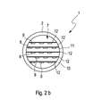
- FIG. 2b a view against the flow direction of the exhaust gas in the exhaust system 1.
- the exhaust system according to the invention is denoted by 1.
- the exhaust system 1 has an exhaust gas purification device 2 in the manner of a diesel oxidation catalyst for purifying exhaust gas 3 discharged from the internal combustion engine of the motor vehicle (not shown). Downstream of or spaced from the exhaust gas purification device 2, a reducing agent supply device 4 is arranged, by means of which a reducing agent, which in FIG. 2a roughly indicated by the reference numeral 5, can be introduced into the exhaust system 1.
- a reducing agent precursor solution for example a urea-water solution, can preferably be introduced into the exhaust system 1.
- the reducing agent precursor can be mixed with the exhaust gas 3 from the exhaust system and thus a reducing agent, in the case of the urea-water solution ammonia (NH 3 ), are generated.
- a reducing agent in the case of the urea-water solution ammonia (NH 3 )
- nitrogen oxides (NO x ) can be reduced to nitrogen (N 2 ).
- this can be injected in a flow direction S in the system 1, at least partially the flow direction of the exhaust gas 3 (see. FIG. 2a ) is directed opposite.
- a reducing agent deflecting device 7 is arranged, which has at least one scoop-like reductant deflecting element 8.
- reducing agent deflecting elements 8 are shown; It is clear that in variants but also a different number of reducing agent deflecting elements 8 may be provided.
- the reducing agent deflecting elements 8 are designed in such a way that the reducing agent or reductant precursor which has been introduced into the exhaust system 1 and is incident on the reducing agent deflecting elements 8 is deflected away from the exhaust gas purification device 2 (see arrows 9).
- the reducing agent deflecting device 7 may be arranged on an outlet side 10 of the exhaust gas purification device 2 and / or fixed.
- the reducing agent deflecting elements 8 can be arranged so as to be opaque in the propagation direction S and / or configured. In this way, it can be particularly well prevented that reducing agent can penetrate into the exhaust gas purification device 2.
- FIG. 2a shows the outlet side 10 defines an outlet cross-sectional area 11 of the exhaust gas purification device 2.
- FIG. 2b shows the exhaust gas purification device 2 with a view towards the outlet cross-sectional area 11.
- five fastening elements 12 are arranged by way of example, which are designed substantially like struts and each end side supported on the outlet side 10 of the exhaust gas purification device 2. It is clear that in variants of the embodiment, a different number of strut-like fastening elements 12 is possible.
- On each of the fasteners 12, a plurality of reducing agent deflecting elements 8 may be arranged. Also in the FIG.
- the fasteners 12 may end to the outlet side 10 of the exhaust gas purification device 2 may be attached, for example by means of welding.
- the reducing agent deflecting elements 8 may be welded to the respective fastening elements 12.
- the reducing agent deflecting elements 8 can also be formed integrally on the respective fastening element 12. At least five, preferably at least ten, most preferably at least twenty, mutually spaced-apart fastening elements 12 are preferably arranged in the region of the outlet cross-sectional area 11.
- the fastening elements 12 can be arranged in a line in the outlet cross-sectional area 11. Since the reducing agent deflecting elements 8 are each arranged at a distance from each other on each fastening element 12, a type of reducing agent deflecting element grid is formed by the reducing agent deflecting elements 8.
- the fasteners 12 may, as in the FIG. 2b shown as an example, may be formed as substantially straight struts, which are arranged substantially parallel and spaced apart in the region of the outlet cross-sectional area 11 of the exhaust gas purification device 2.
- the reducing agent deflecting elements 8 can be arranged in an axial direction A (cf. FIG. 2a ) to be straight.
- the reducing agent deflecting elements 8 along the axial direction A but also in each case curved (see. FIG. 3 ) or angled (cf. FIG. 4 ) and be secured to an attachment member 12 with an axial end portion 13, respectively.
- the fastening elements 12 can be designed as curved struts, which are arranged at a distance from one another in the region of the outlet cross-sectional area 11 of the exhaust gas purification device 2.
- the presentation of the FIG. 6 shows a particular variant of the fasteners 12 and the attached reducing agent deflecting 8.
- the fasteners 12 are formed as a two-part struts with a respective first and second strut element 14, 15.
- the two strut elements 14, 15 are arranged parallel to one another and at a distance from one another in an axial direction A.
- a plurality of reducing agent deflecting elements 8 are arranged in an intermediate area between the first and second strut elements 14, 15 in the axial direction adjacent to each other and spaced from each other and end connected respectively to the first and second strut element 14, 15, for example by welding.
- the reducing agent deflecting elements 8 may also be integrally formed on the two strut elements 14, 15.
- each curved formed reducing agent deflecting elements are shown. It is clear that other variants but also straight trained or angled trained reducing agent deflecting elements 8 (see Fig. 2 and 4 ) are conceivable.
Landscapes
- Chemical & Material Sciences (AREA)
- Engineering & Computer Science (AREA)
- Chemical Kinetics & Catalysis (AREA)
- Health & Medical Sciences (AREA)
- Toxicology (AREA)
- Combustion & Propulsion (AREA)
- Mechanical Engineering (AREA)
- General Engineering & Computer Science (AREA)
- Exhaust Gas After Treatment (AREA)
- Exhaust Gas Treatment By Means Of Catalyst (AREA)
- Treating Waste Gases (AREA)
Description
- Die vorliegende Erfindung betrifft eine Abgasanlage für ein Kraftfahrzeug sowie ein Kraftfahrzeug mit einer solchen Abgasanlage.
- Die in einer Brennkraftmaschine eines Kraftfahrzeugs betriebsmäßig erzeugten Abgase können mit Hilfe eines Fahrzeugkatalysators gereinigt werden, um die Schadstoffemission des Abgases deutlich zu reduzieren. Eine solche Reinigung des Abgases kann durch Zugabe eines Reduktionsmittels zu dem Abgas der Brennkraftmaschine in einer Abgasbehandlungseinrichtung erfolgen. Ein bekanntes Verfahren, welches auf einer derartigen Zugabe eines Reduktionsmittels in das Abgas basiert, ist die sogenannte selektive katalytische Reduktion ("SCR", "Selective Catalytic Reduction"), bei welcher Stickoxid-Verbindungen im Abgas chemisch reduziert werden.
- Eine derartige selektive katalytische Reduktion ist insbesondere in Verbindung mit Brennkraftmaschinen sinnvoll, die bei der Verbrennung von Kraftstoff einen hohen Luftüberschuss erzeugen, wie dies beispielsweise bei Dieselmotoren der Fall ist, in deren Abgas hohe Sauerstoffkonzentrationen vorhanden sind. Aufgrund einer solchen hohen Sauerstoffkonzentration im Abgas ist die Verwendung eines herkömmlichen Drei-Wege-Katalysators zur Reduktion von Stickoxiden nicht möglich. Daher werden in Verbindung mit Dieselmotoren häufig Oxidations-katalysatoren verwendet, welche die Emission von CO und CmHn vermindern. Die katalytisch aktiven Edelmetalle wie beispielsweise Platin oder Palladium können in einen sog. "Washcoat" eingelagert werden.
- Die eigentliche selektive katalytische Reduktion erfolgt in einem dem Diesel-Oxidationskatalysator nachgeschalteten Bereich der Abgasbehandlungsvorrichtung. Als Reduktionsmittel kann Ammoniak zum Einsatz kommen, welches der Abgasbehandlungsvorrichtung zur Verfügung gestellt werden muss. Zur Bereitstellung von Ammoniak in der Abgasanlage wird jedoch üblicherweise Ammoniak nicht direkt in die Abgasanlage eingespritzt, sondern in Form eines Reduktionsmittel-Vorläufers in die Abgasanlage eingebracht. Ein solcher Vorläufer kann beispielsweise eine Harnstoff-Wasser-Lösung sein, die im Handel unter dem Namen "Adblue" bekannt ist. Die Umsetzung eines derartigen Vorläufers zu dem eigentlichen Reduktionsmittel (Ammoniak) kann thermisch oder/und unter Zuhilfenahme eines Katalysators innerhalb eines Abgasstroms in dem der Abgasbehandlungseinrichtung nachgeschalteten Bereich der Brennkraftmaschine erfolgen.
- Die Zuführung des Reduktionsmittels in die Abgasanlage kann beispielsweise durch Eindüsen mittels eines Injektors erfolgen. Ein solcher Injektor kann stromab des eigentlichen Diesel-Oxidationskatalysators angeordnet sein. Bei bestimmten Einbausituationen können bei einer derartigen Anordnung jedoch eingedüste Tröpfchen der Harnstoff-Wasser-Lösung auf die Oberfläche des Diesel-Oxidationskatalysators treffen und dort unerwünschte Ablagerungen bilden. Gleiches gilt für das aus der Harnstoff-Wasser-Lösung gebildete Ammoniak, da ein Kontakt von Ammoniak mit den katalytisch aktiven Edelmetallen des Diesel-Oxidationskatalysators, beispielsweise in einer "Washcoat", zu einer unerwünschten Reaktion des Ammoniak mit Platin bzw. Palladium zu Stickoxiden führen kann.
- Es ist daher eine Aufgabe der vorliegenden Erfindung, eine Ausführungsform bereitzustellen, bei welcher oben genannte Probleme beseitigt oder zumindest reduziert sind.
- Die oben genannte Aufgabe wird gelöst durch den Gegenstand der unabhängigen Ansprüche. Bevorzugte Ausführungsformen sind Gegenstand der abhängigen Ansprüche.
- Die Erfindung beruht auf dem allgemeinen Gedanken, zwischen der Abgasreinigungseinrichtung der Abgasanlage, beispielsweise einem Diesel-Oxidationskatalysator "DOC", und der Reduktionsmittel-Zuführungseinrichtung, beispielsweise in der Art eines Injektors zum Einbringen einer Harnstoff-Wasser-Lösung in die Abgasanlage, eine Reduktionsmittel-Ablenkeinrichtung vorzusehen, welche wenigstens ein schaufelartig ausgebildetes Reduktionsmittel-Ablenkelement aufweist.
- Mittels einer derartigen Reduktionsmittel-Ablenkeinrichtung kann erreicht werden, dass ein unerwünschter Kontakt zwischen dem Vorläufer des Reduktionsmittels, also beispielsweise einer Harnstoff-Wasser-Lösung bzw. des Reduktionsmittels selbst, beispielsweise Ammoniak, und der Abgasreinigungseinrichtung, beispielsweise eines Diesel-Oxidationskatalysators, vermieden wird. Dies gilt insbesondere für die in der Abgasreinigungseinrichtung katalytisch aktiven Edelmetalle.
- Reduktionsmittel und Reduktionsmittel-Vorläufer Wasser-Lösung können mittels des wenigstens einen Reduktionsmittel-Ablenkelements von der Abgasreinigungseinrichtung abgelenkt werden, so dass weitgehend oder vollständig verhindert werden kann, dass der Vorläufer bzw. das aus dem Vorläufer gebildete Reduktionsmittel in den Diesel-Oxidationskatalysator eindringen kann.
- Auf diese Weise wird die unerwünschte Bildung von Ablagerungen bzw. Nebenprodukten, wie z.B. Stickoxiden, in der Abgasreinigungseinrichtung zum großen Teil oder sogar vollständig vermieden, was wiederum zu einer Verbesserung der Leistungsfähigkeit der Abgasanlage führt.
- Die erfindungsgemäße Abgasanlage umfasst eine Abgasreinigungseinrichtung zur Reinigung von aus einer Brennkraftmaschine des Kraftfahrzeugs abgeführtem Abgas sowie eine stromab und beabstandet zur Abgasreinigungseinrichtung angeordnete Reduktionsmittel-Zuführungseinrichtung. Mittels einer solchen Reduktionsmittel-Zuführungseinrichtung kann Reduktionsmittel in die Abgasanlage eingebracht werden. Unter dem Begriff "Reduktionsmittel-Zuführungseinrichtung" ist dabei nicht nur eine Einrichtung zu verstehen, welche ein Reduktionsmittel, z.B. Ammoniak, direkt in die Abgasanlage einbringt; vielmehr ist unter diesem Begriff ausdrücklich auch die indirekte Zuführung des Reduktionsmittels derart zu verstehen, dass mittels der Reduktionsmittel-Zuführungseinrichtung ein Vorläufer des Reduktionsmittels, z.B. eine Harnstoff-Wasser-Lösung, in die Abgasanlage eingebracht wird und dieser Vorläufer in der Abgasanlage mittels thermischer Reaktion o.ä. zu dem eigentlichen Reduktionsmittel reagiert.
- Entsprechend einer vorteilhaften Ausführungsform kann die Reduktionsmittel-Zuführungseinrichtung so ausgestaltet und/oder angeordnet sein, dass eine Strömungsrichtung, mit der das Reduktionsmittel in die Abgasanlage eingebracht wird, wenigstens teilweise entgegengesetzt zur Strömungsrichtung des Abgases in der Abgasanlage verläuft. Mit anderen Worten, das Reduktionsmittel wird so eingebracht, dass es zumindest zu Beginn eine Ausbreitungs- bzw. Bewegungsrichtung aufweist, die eine der Abgasströmungsrichtung entgegengesetzte Richtungskomponente aufweist, so dass sich das Reduktionsmittel in Richtung auf die stromauf angeordnete Abgasreinigungseinrichtung bewegt. Hierdurch wird eine zur Verdampfung des Reduktionsmittels sowie zur Vermischung mit dem Abgas zur Verfügung stehende Zeit vergrößert, was die Effizienz der Reduktionsmitteleinbringung auf engem Raum verbessert. Bevorzugt ist die (Haupt-) Strömungsrichtung des Reduktionsmittels um 45°±30°, insbesondere um 45°±15°, gegenüber der (Haupt-) Strömungsrichtung des Abgases geneigt.
- In einer bevorzugten Ausführungsform kann das Reduktionsmittel-Ablenkelement derart ausgebildet sein, dass von der Reduktionsmittel-Zuführungseinrichtung in die Abgasanlage eingebrachtes und auf das Reduktionsmittel-Ablenkelement treffendes Reduktionsmittel von der Abgasreinigungseinrichtung weggerichtet abgelenkt wird. Mittels einer derartigen Ablenkung wird erreicht, dass nur ein sehr geringer Anteil des von der Reduktionsmittel-Zuführungseinrichtung in die Abgasanlage eingebrachten Reduktionsmittels in die Abgasreinigungseinrichtung gelangen und dort zu unerwünschten Nebenprodukten bzw. Ablagerungen führen kann. Idealerweise gelangt gar kein Reduktionsmittel in die Abgasreinigungseinrichtung. Mit einem derartigen, weggerichteten Ablenken des Reduktionsmittels mittels der Reduktionsmittel-Ablenkeinrichtung und deren Reduktionsmittel-Ablenkelement(en) wird erreicht, dass die Bauteile der Abgasreinigungseinrichtung, insbesondere deren Oberfläche, z.B. eine Platin-Beschichtung, nicht von dem Reduktionsmittel berührt und kontaminiert werden, so dass eine unerwünschte chemische Reaktionen des Reduktionsmittels mit der Oberfläche der Abgasreinigungseinrichtung vermieden werden kann.
- Bei einer anderen Ausführungsform kann zusätzlich oder alternativ vorgesehen sein, dass das Reduktionsmittel-Ablenkelement derart ausgebildet ist, dass von der Reduktionsmittel-Zuführungseinrichtung in die Abgasanlage eingebrachtes und auf das Reduktionsmittel-Ablenkelement treffendes flüssiges Reduktionsmittel verdampft wird. Durch Bereitstellen einer Aufprall- und Verdampferfläche kann die Verdampfung des Reduktionsmittels unterstützt werden. Insbesondere kann das Reduktionsmittel-Ablenkelement die jeweilige Verdampferfläche bezüglich der Abgasströmung abströmseitig aufweisen, so dass diese durch die ankommende Abgasströmung beheizt wird, was die Verdampfung unterstützt. Besonders vorteilhaft ist eine Ausführungsform, bei welcher die Einbringung des flüssigen Reduktionsmittels gezielt so erfolgt, dass es zu einer Beaufschlagung des Reduktionsmittel-Ablenkelements mit Reduktionsmittel kommt, derart, dass ein Wesentlicher Anteil der Verdampfung am Reduktionsmittel-Ablenkelement erfolgt. Hierdurch kann eine Mischstrecke zwischen der Abgasreinigungseinrichtung und einem gegebenenfalls stromab davon angeordneten SCR-Katalysators vergrößert bzw. besser ausgenutzt werden.
- In einer besonders bevorzugten Ausführungsform ist die Reduktionsmittel-Ablenkeinrichtung an einer Auslassseite der Abgasreinigungseinrichtung angeordnet oder/und befestigt. Auf diese Weise kann die Reduktionsmittel-Ablenkeinrichtung besonders wirksam eingesetzt werden, wenn Reduktionsmittel oder ein Vorläufer davon mittels der Reduktionsmittel-Zuführungseinrichtung stromab der Abgasreinigungseinrichtung in die Abgasanlage eingebracht wird und entgegen einer Stromrichtung des Abgases in die Abgasanlage eingespritzt wird.
- Die Reduktionsmittel-Ablenkeinrichtung kann dabei als separates Bauteil ausgebildet sein, welches stromab der Abgasreinigungseinrichtung im Abgasstrang angebracht ist; in einer technisch besonders einfach herzustellenden Ausführungsform kann die Reduktionsmittel-Ablenkeinrichtung aber auch direkt an der Aus-lassseite der Abgasreinigungseinrichtung befestigt sein, beispielsweise mittels Verschweißen o. ä..
- Um die Abgasreinigungseinrichtung besonders gut vor dem in die Abgasanlage eingespritzten Reduktionsmittel bzw. dessen Vorläufer zu schützen, kann die Reduktionsmittel-Ablenkeinrichtung nicht nur ein einziges Reduktionsmittel-Ablenkelement, sondern eine Mehrzahl solcher Reduktionsmittel-Ablenkelemente umfassen, welche allesamt im Bereich der Auslassseite der Abgasreinigungseinrichtung angeordnet sind.
- Einen besonders hohen Wirkungsquerschnitt der Reduktionsmittel-Ablenkeinrichtung kann eine blickdichte Anordnung oder/und eine blickdichte Ausgestaltung der Reduktionsmittel-Ablenkelemente in einer Ausbreitungsrichtung des Reduktionsmittels bzw. Vorläufer zur Auslassseite hin erzielen. Dabei ist unter "Ausbreitungsrichtung" eine Richtung zu verstehen, in welcher das Reduktionsmittel bzw. dessen Vorläufer mittels der Reduktionsmittel-Zuführungseinrichtung in die Abgasanlage eingedüst wird.
- In einer weiterbildenden Ausführungsform kann daran gedacht sein, dass die Auslassseite eine Auslass-Querschnittsfläche der Abgasreinigungseinrichtung definiert. In diesem Bereich der Auslass-Querschnittsfläche kann wenigstens ein im Wesentlichen strebenartig ausgebildetes Befestigungselement angeordnet sein, welches sich jeweils endseitig an der Auslassöffnung abstützt. An dem wenigstens einen Befestigungselement wiederum kann wenigstens ein Reduktionsmittel-Ablenkelement angeordnet sein. Das im Wesentlichen strebenartig ausgebildete Befestigungselement kann beispielsweise mittels Verschweißen an der Auslassöffnung befestigt sein. Durch die Verwendung eines im Wesentlichen strebenartig ausgebildeten Befestigungselements kann eine mechanisch besonders stabile Anordnung der Reduktionsmittel-Ablenkelemente im Bereich der Auslassseite erzielt werden und optional auch die vorangehend erläuterte blickdichte Anordnung bzw. Ausgestaltung auf einfache Weise verwirklicht werden.
- In einer technisch besonders einfach herzustellenden und somit kostengünstigen Ausführungsform kann das Reduktionsmittel-Ablenkelement integral am Befestigungselement ausgeformt sein.
- In einer besonders bevorzugten Ausführungsform, welche für den Praxisbetrieb der Abgasanlage in einem Kraftfahrzeug geeignet ist, können im Bereich der Auslass-Querschnittsfläche wenigstens zwei, vorzugsweise fünf, höchst vorzugsweise zehn, zueinander beabstandet angeordnete Befestigungselemente angeordnet sein. Ein jedes Befestigungselement kann dabei dann in der Art einer Strebe ausgebildet sein. Die Bereitstellung einer Mehrzahl solcher Befestigungselemente ermöglicht die Anordnung einer großen Anzahl von Reduktionsmittel-Ablenkelementen auf diesen Befestigungselementen, was wiederum eine besonders wirksame Ablenkung von in die Abgasanlage eingebrachten Reduktionsmittel bzw. dessen Vorläufer ermöglicht.
- Vorzugsweise können die Befestigungselemente zeilenartig in der Auslass-Querschnittsfläche angeordnet sein. Die Reduktionsmittel-Ablenkelemente können dann jeweils beabstandet zueinander auf einem Befestigungselement angebracht sein, so dass durch die Reduktionsmittel-Ablenkelemente ein Reduktionsmittel-Ablenkelemente-Raster ausgebildet ist. Mittels einer derartigen rasterartigen Anordnung der Reduktionsmittel-Ablenkelemente wird eine besonders effektive Ablenkung von Reduktionsmittel bzw. dessen Vorläufer erzielt.
- In einer technisch besonders einfach herzustellenden Ausführungsform können die Befestigungselemente jeweils als gerade Streben ausgebildet sein. Diese Streben sind im Wesentlichen parallel und beabstandet zueinander im Bereich der Auslass-Querschnittsfläche der Abgasreinigungseinrichtung angeordnet.
- In einer dazu alternativen Variante können die Befestigungselemente jeweils als gekrümmte Streben ausgebildet sein, die ebenfalls beabstandet zueinander im Bereich der Auslass-Querschnittsfläche der Abgasreinigungseinrichtung angeordnet sein können.
- Eine verbesserte Ablenkung von Reduktionsmittel bzw. dessen Vorläufer durch die Reduktionsmittel-Ablenkelemente wird durch eine in der Axialrichtung gekrümmte oder abgewinkelte Ausbildung der Reduktionsmittel-Ablenkelemente gemäß einer bevorzugten Ausführungsform erzielt. Gemäß dieser Ausführungsform sind die Reduktionsmittel-Ablenkelemente an einem axialen Endabschnitt eines jeweiligen Befestigungselements befestigt.
- Die Erfindung betrifft des Weiteren ein Kraftfahrzeug mit einer Abgasanlage mit einem oder mehreren der vorhergehend genannten Merkmale sowie mit einer stromauf der Abgasanlage angeordneten und mit dieser fluidisch verbundenen Brennkraftmaschine.
- Weitere wichtige Merkmale und Vorteile der Erfindung ergeben sich aus den Unteransprüchen, aus den Zeichnungen und aus der zugehörigen Figurenbeschreibung anhand der Zeichnungen.
- Es versteht sich, dass die vorstehend genannten und die nachstehend noch zu erläuternden Merkmale nicht nur in der jeweils angegebenen Kombination, sondern auch in anderen Kombinationen oder in Alleinstellung verwendbar sind, ohne den Rahmen der vorliegenden Erfindung zu verlassen.
- Bevorzugte Ausführungsbeispiele der Erfindung sind in den Zeichnungen dargestellt und werden in der nachfolgenden Beschreibung näher erläutert, wobei sich gleiche Bezugszeichen auf gleiche oder ähnliche oder funktional gleiche Komponenten beziehen.
- Es zeigen, jeweils schematisch
- Fig. 1
- eine aus dem Stand der Technik bekannte Abgasanlage in einer grobschematischen Ansicht,
- Fig. 2a/2b
- eine erfindungsgemäße Abgasanlage in einer grobschematischen Ansicht, wobei die
Figur 2a eine Seitenansicht und dieFigur 2b eine Rückansicht zeigt, - Fig.3
- eine erste Variante des Ausführungsbeispiel der
Figur 2 mit gekrümmt ausgebildeten Ablenkelementen, - Fig.4
- eine zweite Variante des Ausführungsbeispiel der
Figur 2 mit abgewinkelt ausgebildeten Ablenkelementen, - Fig.5
- eine dritte Variante des Ausführungsbeispiel der
Figur 2 mit gekrümmt ausgebildeten Befestigungselementen, - Fig.6
- eine vierte Variante des Ausführungsbeispiel der
Figur 2 mit zweiteilig ausgebildeten Befestigungselementen. - In der Darstellung der
Figur 1 ist eine Abgasanlage grobschematisch gezeigt und mit 100 bezeichnet. Die Abgasanlage 100 umfasst eine Abgasreinigungseinrichtung 101, die beispielsweise als Diesel-Oxidationskatalysator zur Reinigung von aus einer Brennkraftmaschine (nicht gezeigt) des Kraftfahrzeugs abgeführtem Abgas (vergleiche Pfeil 102) ausgebildet sein kann. Mittels eines solchen Diesel-Oxidationskatalysators kann beispielsweise die Emission von CO und CmHn im Abgas 102 reduziert werden. - Zum Zwecke der selektiven katalytischen Reduktion kann stromab der Abgasreinigungseinrichtung 101 eine Reduktionsmittel-Zuführungseinrichtung 103 in der Art eines Injektors angeordnet sein. Mittels der Reduktionsmittel-Zuführungseinrichtung 103 kann ein Reduktionsmittel-Vorläufer, beispielsweise eine Harnstoff-Wasser-Lösung, in die Abgasanlage 100 eingebracht werden. Diese Harnstoff-Wasser-Lösung kann im Bereich 104 stromab der Abgasreinigungseinrichtung 101 thermisch und/oder unter Zuhilfenahme eines Katalysators innerhalb des Abgasstromes in ein Reduktionsmittel (wie z.B. Ammoniak) umgewandelt werden. Dem Bereich 104 kann ein Partikelfilter 106 ("SDPF") nachgeschaltet sein. Zur effektiven Vermischung der Harnstoff-Wasser-Lösung im Abgas kann im Bereich 104 ein geeignetes Durchmischungselement, beispielsweise in der Art eines Wabenmischers oder ähnlichem, angeordnet sein (in der
Figur 1 der Übersichtlichkeit halber nicht gezeigt). Alternativ dazu kann eine Strömungsrichtung R der Harnstoff-Wasser-Lösung, die mittels des Injektors 103 im Bereich 104 der Abgasanlage eingespritzt wird, wie in derFigur 1 gezeigt, wenigstens teilweise entgegengesetzt zur Strömungsrichtung 102 des Abgases in der Abgasanlage 100 verlaufen, um auf diese Weise eine besonders gute Durchmischung des Abgases mit der Harnstoff-Wasser-Lösung zu erzielen. - Nachteilig daran ist jedoch, dass ein Teil der Harnstoff-Wasser-Lösung, der in der
Figur 1 mit dem Bezugszeichen 105 bezeichnet ist, in die Abgasreinigungseinrichtung 101 eindringen kann und in dieser unerwünschte Ablagerungen oder ähnliches ausbilden kann. Des Weiteren kann die Harnstoff-Wasser-Lösung bzw. der aus dieser gebildete Ammoniak (NH3) mit einer Oberflächenbeschichtung, beispielsweise Palladium oder Platin, der Abgasreinigungseinrichtung 101 zu Stickoxiden (NOx) reagieren. Beide Effekte führen zu einer verringerten Reinigungsfähigkeit der Abgasanlage 100. - Auch für den Fall, dass im Bereich 104 der Abgasanlage 100 ein Wabenmischer oder ähnliches zur besonders effektiven Durchmischung der Harnstoff-Wasser-Lösung mit dem Abgas der Abgasanlage 100 erreicht werden kann, besteht die Gefahr, dass von dem Wabenmischer reflektiertes Reduktionsmittel in analoger Weise in den Diesel-Oxidationskatalysator eindringen und dort zu oben erwähnten Ablagerungen bzw. unerwünschten Nebenprodukten (z.B. NOx) führen kann. Demgegenüber ist in der Darstellung der
Figur 2 eine erfindungsgemäße Abgasanlage dargestellt. DieFigur 2a zeigt dabei eine grobschematische Seitenansicht, dieFigur 2b eine Ansicht gegen die Strömungsrichtung des Abgases in der Abgasanlage 1. In derFigur 2 ist die erfindungsgemäße Abgasanlage mit 1 bezeichnet. - Die Abgasanlage 1 weist eine Abgasreinigungseinrichtung 2 in der Art eines Diesel-Oxidationskatalysators zur Reinigung von aus der Brennkraftmaschine des Kraftfahrzeugs (nicht gezeigt) abgeführtem Abgas 3 auf. Stromab oder beabstandet zur Abgasreinigungseinrichtung 2 ist eine Reduktionsmittel-Zuführungseinrichtung 4 angeordnet, mittels welcher ein Reduktionsmittel, welches in
Figur 2a grobschematisch angedeutet und mit dem Bezugszeichen 5 bezeichnet ist, in die Abgasanlage 1 eingebracht werden kann. Mittels der Reduktionsmittel-Zuführungseinrichtung 4 kann vorzugsweise eine Reduktionsmittel-Vorläuferlösung, beispielsweise eine Harnstoff-Wasser-Lösung, in die Abgasanlage 1 eingebracht werden. In einem Bereich 6 stromab der Abgasreinigungseinrichtung 2 kann der Reduktionsmittel-Vorläufer mit dem Abgas 3 aus der Abgasanlage vermischt werden und somit ein Reduktionsmittel, im Falle der Harnstoff-Wasser-Lösung Ammoniak (NH3), erzeugt werden. Mittels des Reduktionsmittels können in dem Abgas 3 enthaltene Stickoxide (NOx) zu Stickstoff (N2) reduziert werden. - Zur effektiven Durchmischung des Reduktionsmittel-Vorläufers mit dem Abgas kann dieses in einer Strömungsrichtung S in die Anlage 1 eingespritzt werden, die wenigstens teilweise der Strömungsrichtung des Abgases 3 (vgl.
Figur 2a ) entgegengerichtet ist. Um zu verhindern, dass das aus der ReduktionsmittelVorläuferlösung bzw. gebildete Reduktionsmittel auf unerwünschte Weise in die Abgasreinigungseinrichtung 2 eintreten kann, ist erfindungsgemäß zwischen der Abgasreinigungseinrichtung 2 und der Reduktionsmittel-Zuführungseinrichtung 4 eine Reduktionsmittel-Ablenkeinrichtung 7 angeordnet, die wenigstens ein schaufelartig ausgebildetes Reduktionsmittel-Ablenkelement 8 aufweist. - In der Darstellung der
Figur 2a sind exemplarisch acht solcher ReduktionsmittelAblenkelemente 8 gezeigt; es ist klar, dass in Varianten aber auch eine andere Anzahl an Reduktionsmittel-Ablenkelementen 8 vorgesehen sein kann. Die Reduktionsmittel-Ablenkelemente 8 sind derart ausgebildet, dass das von der Reduktionsmittel-Zuführungseinrichtung 7 in die Abgasanlage 1 eingebrachte und auf die Reduktionsmittel-Ablenkelemente 8 treffende Reduktionsmittel bzw. der Reduktionsmittel-Vorläufer von der Abgasreinigungseinrichtung 2 weggerichtet abgelenkt wird (vergleiche Pfeile 9). Die Reduktionsmittel-Ablenkeinrichtung 7 kann an einer Auslassseite 10 der Abgasreinigungseinrichtung 2 angeordnet oder/und befestigt sein. Die Reduktionsmittel-Ablenkelemente 8 können in einer bevorzugten Variante in der Ausbreitungsrichtung S blickdicht angeordnet oder/und ausgestaltet sein. Auf diese Weise lässt sich besonders gut verhindern, dass Reduktionsmittel in die Abgasreinigungseinrichtung 2 eindringen kann. - Aus der Darstellung der
Figur 2a lässt sich auch entnehmen, dass die Auslassseite 10 eine Auslass-Querschnittsfläche 11 der Abgasreinigungseinrichtung 2 definiert. DieFigur 2b zeigt die Abgasreinigungseinrichtung 2 mit Blickrichtung auf die Auslass-Querschnittsfläche 11. Im Bereich der Auslass-Querschnittsfläche 11 sind exemplarisch fünf Befestigungselemente 12 angeordnet, die im Wesentlichen strebenartig ausgebildet sind und sich jeweils endseitig an der Auslassseite 10 der Abgasreinigungseinrichtung 2 abstützen. Es ist klar, dass in Varianten des Ausführungsbeispiels auch eine andere Anzahl an strebenartig ausgebildeten Befestigungselementen 12 möglich ist. Auf jedem der Befestigungselemente 12 können mehrere Reduktionsmittel-Ablenkelemente 8 angeordnet sein. Auch die in derFigur 2b gezeigte jeweilige Anzahl an solchen Ablenkelementen ist nur exemplarisch anzusehen. Die Befestigungselemente 12 können endseitig an der Auslassseite 10 der Abgasreinigungseinrichtung 2 befestigt sein, beispielsweise mittels Verschweißen. Ebenso können die Reduktionsmittel-Ablenkelemente 8 an den jeweiligen Befestigungselementen 12 angeschweißt sein. In einer Variante können die Reduktionsmittel-Ablenkelemente 8 aber auch integral am jeweiligen Befestigungselement 12 ausgeformt sein. Bevorzugt sind im Bereich der AuslassQuerschnittsfläche 11 wenigstens fünf, vorzugsweise wenigstens zehn, höchst vorzugsweise wenigstens zwanzig, zueinander beabstandet angeordnete Befestigungselemente 12 angeordnet. - Aus der Darstellung der
Figur 2b kann man entnehmen, dass die Befestigungselemente 12 zeilenartig in der Auslass-Querschnittsfläche 11 angeordnet sein können. Da auf jedem Befestigungselement 12 die Reduktionsmittel-Ablenkelemente 8 jeweils beabstandet zueinander angeordnet sind, wird durch die Reduktionsmittel-Ablenkelemente 8 eine Art Reduktionsmittel-Ablenkelemente-Raster ausgebildet. - Die Befestigungselemente 12 können, wie in der
Figur 2b exemplarisch gezeigt, jeweils als im Wesentlichen gerade Streben ausgebildet sein, die im Wesentlichen parallel und beabstandet zueinander im Bereich der Auslass-Querschnittsfläche 11 der Abgasreinigungseinrichtung 2 angeordnet sind. - Die Reduktionsmittel-Ablenkelemente 8 können in einer Axialrichtung A (vgl.
Figur 2a ) gerade ausgebildet sein. - In den in den
Figuren 3 und 4 gezeigten Varianten können die Reduktionsmittel-Ablenkelemente 8 entlang der axialen Richtung A aber auch jeweils gekrümmt (vgl.Figur 3 ) oder abgewinkelt (vgl.Figur 4 ) ausgebildet sein und mit einem axialen Endabschnitt 13 jeweils an einem Befestigungselement 12 befestigt sein. - In einer in der
Figur 5 gezeigten Variante können die Befestigungselemente 12 als jeweils gekrümmte Streben ausgebildet sein, welche zueinander beabstandet im Bereich der Auslass-Querschnittsfläche 11 der Abgasreinigungseinrichtung 2 angeordnet sind. - Die Darstellung der
Figur 6 zeigt schließlich eine besondere Variante der Befestigungselemente 12 bzw. der daran befestigten Reduktionsmittel-Ablenkelemente 8. Die Befestigungselemente 12 sind dabei als zweiteilige Streben mit einem jeweils ersten und zweiten Strebenelement 14, 15 ausgebildet. Die beiden Strebenelemente 14, 15 sind parallel zueinander und beabstandet zueinander in einer axialen Richtung A verlaufend angeordnet. Mehrere Reduktionsmittel-Ablenkelemente 8 sind in einem Zwischenbereich zwischen dem ersten und zweiten Strebenelement 14, 15 in der Axialrichtung benachbart und zueinander beabstandet angeordnet und endseitig jeweils mit dem ersten und zweiten Strebenelement 14, 15, beispielsweise mittels Verschweißen, verbunden. Alternativ dazu können die Reduktionsmittel-Ablenkelemente 8 aber auch integral an den beiden Strebenelementen 14, 15 ausgeformt sein. - In der Darstellung der
Figur 6 sind jeweils gekrümmt ausgebildete Reduktionsmittel-Ablenkelemente gezeigt. Es ist klar, dass weitere Varianten aber auch gerade ausgebildete oder abgewinkelt ausgebildete Reduktionsmittel-Ablenkelemente 8 (vgl. hierzuFig. 2 und4 ) vorstellbar sind.
Claims (15)
- Abgasanlage für ein Kraftfahrzeug,- mit einer Abgasreinigungseinrichtung (2) zur Reinigung von aus einer Brennkraftmaschine des Kraftfahrzeugs abgeführtem Abgas (3),- mit einer stromab und beabstandet zur Abgasreinigungseinrichtung (2) angeordneten Reduktionsmittel-Zuführungseinrichtung (4), mittels welcher ein Reduktionsmittel in die Abgasanlage (1; 100) einbringbar ist,- mit einer zwischen der Abgasreinigungseinrichtung (2) und der Reduktionsmittel-Zuführungseinrichtung (4) angebrachten Reduktionsmittel-Ablenkeinrichtung (7), welche wenigstens ein schaufelartig ausgebildetes Reduktionsmittel-Ablenkelement (8) aufweist.
- Abgasanlage nach Anspruch 1,
dadurch gekennzeichnet, dass
eine Strömungsrichtung (R), mit der das Reduktionsmittel in die Abgasanlage (1; 100) eingebracht wird, wenigstens teilweise entgegengesetzt zur Strömungsrichtung (102) des Abgases in der Abgasanlage (1; 100) verläuft. - Abgasanlage nach Anspruch 1 oder 2,
dadurch gekennzeichnet, dass
das Reduktionsmittel-Ablenkelement (7) derart ausgebildet ist, dass von der Reduktionsmittel-Zuführungseinrichtung (4) in die Abgasanlage (1) eingebrachtes und auf das Reduktionsmittel-Ablenkelement (8) treffendes Reduktionsmittel von der Abgasreinigungseinrichtung (2) weggerichtet abgelenkt wird. - Abgasanlage nach einem der Ansprüche 1 bis 3,
dadurch gekennzeichnet, dass
das Reduktionsmittel-Ablenkelement (7) derart ausgebildet ist, dass von der Reduktionsmittel-Zuführungseinrichtung (4) in die Abgasanlage (1) eingebrachtes und auf das Reduktionsmittel-Ablenkelement (8) treffendes Reduktionsmittel verdampft wird. - Abgasanlage nach einem der Ansprüche 1 bis 4,
dadurch gekennzeichnet, dass
die Reduktionsmittel-Ablenkeinrichtung (7) an einer Auslassseite (10) der Abgasreinigungseinrichtung (2) angeordnet oder/und befestigt ist. - Abgasanlage nach einem der vorhergehenden Ansprüche,
dadurch gekennzeichnet, dass
die Reduktionsmittel-Ablenkeinrichtung (7) eine Mehrzahl von Reduktionsmittel-Ablenkelementen (8) umfasst, die im Bereich der Auslassseite (10) der Abgasreinigungseinrichtung (2) angeordnet sind. - Abgasanlage nach Anspruch 6,
dadurch gekennzeichnet, dass
die Reduktionsmittel-Ablenkelemente (8) in einer Ausbreitungsrichtung (S) des Reduktionsmittels zur Auslassseite (10) blickdicht angeordnet oder/und ausgestaltet sind. - Abgasanlage nach Anspruch 6 oder 7,
dadurch gekennzeichnet, dass- die Auslassseite (10) eine Auslass-Querschnittsfläche (211) der Abgasreinigungseinrichtung (2) definiert,- im Bereich der Auslass-Querschnittfläche (11) wenigstens ein im Wesentlichen strebenartig ausgebildetes Befestigungselement (12) angeordnet ist, welches sich jeweils endseitig an der Auslassseite (10) der Abgasreinigungseinrichtung (2) abstützt,- an dem wenigstens einen Befestigungselement (12) wenigstens ein Reduktionsmittel-Ablenkelement (8) angeordnet ist. - Abgasanlage einem der vorhergehenden Ansprüche,
dadurch gekennzeichnet, dass
das Reduktionsmittel-Ablenkelement (8) integral am Befestigungselement (12) ausgeformt ist. - Abgasanlage nach Anspruch 8 oder 9,
dadurch gekennzeichnet, dass
im Bereich der Auslass-Querschnittsfläche (11) wenigstens fünf, vorzugsweise wenigstens zehn, höchst vorzugsweise wenigstens zwanzig, zueinander beabstandet angeordnete Befestigungselemente (12) angeordnet sind. - Abgasanlage nach einem der Ansprüche 8 bis 10,
dadurch gekennzeichnet, dass- die Befestigungselemente (12) zeilenartig in der Auslass-Querschnittsfläche (11) angeordnet sind,- die Reduktionsmittel-Ablenkelemente (8) jeweils beabstandet zueinander auf einem Befestigungselement (12) angebracht sind, so dass durch die Reduktionsmittel-Ablenkelemente (8) ein Reduktionsmittel-Ablenkelemente-Raster ausgebildet ist. - Abgasanlage nach einem der Ansprüche 8 bis 11,
dadurch gekennzeichnet, dass
die Befestigungselemente (12) jeweils als gerade Streben ausgebildet sind, die im Wesentlichen parallel und beabstandet zueinander im Bereich der Auslass-Querschnittsfläche (11) der Abgasreinigungseinrichtung (2) angeordnet sind. - Abgasanlage nach einem der Ansprüche 8 bis 12,
dadurch gekennzeichnet, dass
die Befestigungselemente (12) jeweils als gekrümmte Streben ausgebildet sind, die beabstandet zueinander im Bereich der Auslass-Querschnittsfläche der Abgasreinigungseinrichtung (2) angeordnet sind. - Abgasanlage nach einem der vorhergehenden Ansprüche,
dadurch gekennzeichnet, dass
die Reduktionsmittel-Ablenkelemente (8) in einer Axialrichtung (A) jeweils gekrümmt oder abgewinkelt ausgebildet sind und mit einem axialen Endabschnitt (13) an einem Befestigungselement (12) befestigt sind. - Kraftfahrzeug,- mit einer Abgasanlage (1; 100) nach einem der vorhergehenden Ansprüche,- mit einer stromauf der Abgasanlage (1; 100) angeordneten und mit dieser fluidisch verbundenen Brennkraftmaschine.
Applications Claiming Priority (1)
| Application Number | Priority Date | Filing Date | Title |
|---|---|---|---|
| DE102012216923.7A DE102012216923B4 (de) | 2012-09-20 | 2012-09-20 | Abgasanlage für ein Kraftfahrzeug |
Publications (3)
| Publication Number | Publication Date |
|---|---|
| EP2711518A2 true EP2711518A2 (de) | 2014-03-26 |
| EP2711518A3 EP2711518A3 (de) | 2017-03-29 |
| EP2711518B1 EP2711518B1 (de) | 2020-02-26 |
Family
ID=49230525
Family Applications (1)
| Application Number | Title | Priority Date | Filing Date |
|---|---|---|---|
| EP13184763.4A Active EP2711518B1 (de) | 2012-09-20 | 2013-09-17 | Abgasanlage für ein Kraftfahrzeug |
Country Status (5)
| Country | Link |
|---|---|
| US (2) | US20140075925A1 (de) |
| EP (1) | EP2711518B1 (de) |
| JP (1) | JP5808783B2 (de) |
| CN (1) | CN103670619B (de) |
| DE (1) | DE102012216923B4 (de) |
Families Citing this family (10)
| Publication number | Priority date | Publication date | Assignee | Title |
|---|---|---|---|---|
| KR101498177B1 (ko) * | 2014-11-25 | 2015-03-04 | 세종공업 주식회사 | 다층판형 우레아 믹싱장치 |
| KR101498181B1 (ko) * | 2014-11-25 | 2015-03-04 | 세종공업 주식회사 | 이중 분사형 우레아 믹싱장치 |
| KR101498182B1 (ko) * | 2014-11-25 | 2015-03-04 | 세종공업 주식회사 | 배기가스 정화장치 |
| DE102015209165B4 (de) | 2015-05-20 | 2023-08-03 | Volkswagen Aktiengesellschaft | Abgasbehandlungseinrichtung für eine Brennkraftmaschine |
| US9890682B2 (en) | 2016-04-08 | 2018-02-13 | Caterpillar Inc. | System, apparatus, and method to address unwanted DEF-based deposits in diesel exhaust system |
| KR101837555B1 (ko) * | 2016-07-20 | 2018-03-12 | 융진기업 주식회사 | Scr 믹서 및 이를 포함하는 scr 장치 |
| DE102016014966B4 (de) | 2016-12-15 | 2023-04-20 | Daimler Truck AG | Abgasnachbehandlungseinrichtung für einen Kraftwagen |
| DE102019208825A1 (de) * | 2019-06-18 | 2020-12-24 | Robert Bosch Gmbh | Abgasstrang zur Abgasnachbehandlung |
| EP4063625B1 (de) | 2021-03-25 | 2024-11-13 | Volvo Truck Corporation | Abgasnachbehandlungseinheit zur reinigung von abgasen |
| EP4063627B1 (de) * | 2021-03-25 | 2024-12-11 | Volvo Truck Corporation | Abgasnachbehandlungsanordnung zur konvertierung von nox-emissionen |
Family Cites Families (21)
| Publication number | Priority date | Publication date | Assignee | Title |
|---|---|---|---|---|
| DE10131803A1 (de) * | 2001-06-30 | 2003-05-28 | Bosch Gmbh Robert | Mischeinrichtung für eine Abgasreinigungsanlage |
| WO2005073527A1 (ja) * | 2004-02-02 | 2005-08-11 | Nissan Diesel Motor Co., Ltd. | 内燃機関の排気浄化装置 |
| JP2007032472A (ja) * | 2005-07-28 | 2007-02-08 | Hitachi Ltd | 尿素水を用いた排気処理装置 |
| SE529591C2 (sv) * | 2006-02-08 | 2007-09-25 | Stt Emtec Ab | Insprutningsanordning |
| DE102006024778B3 (de) * | 2006-03-02 | 2007-07-19 | J. Eberspächer GmbH & Co. KG | Statischer Mischer und Abgasbehandlungseinrichtung |
| DE102006038904A1 (de) * | 2006-08-18 | 2008-02-21 | Emitec Gesellschaft Für Emissionstechnologie Mbh | Verfahren zur Zugabe mindestens eines Reaktanden zu einem Abgasstrom und Vorrichtung zur Aufbereitung eines Abgasstroms einer Verbrennungskraftmaschine |
| DE102006055036B4 (de) * | 2006-11-22 | 2023-03-02 | Faurecia Emissions Control Technologies, Germany Gmbh | Mischelement sowie Abgasanlage für eine Verbrennungskraftmaschine |
| DE102007009890B4 (de) * | 2007-02-28 | 2025-05-28 | Emcon Technologies Germany (Augsburg) Gmbh | Statisches Mischelement sowie Verfahren zur Herstellung eines statischen Mischelements |
| DE102007020812B4 (de) * | 2007-05-04 | 2010-01-14 | Audi Ag | Vorrichtung und Verfahren zur Zudosierung von fluiden schadstoffreduzierenden Medien in einen Abgaskanal einer Brennkraftmaschine |
| US7788907B2 (en) * | 2007-06-08 | 2010-09-07 | Ford Global Technologies, Llc | Exhaust injector spray target |
| US7814745B2 (en) * | 2007-07-17 | 2010-10-19 | Ford Global Technologies, Llc | Approach for delivering a liquid reductant into an exhaust flow of a fuel burning engine |
| JP4375465B2 (ja) * | 2007-09-14 | 2009-12-02 | トヨタ自動車株式会社 | 排気通路の添加剤分散板構造 |
| JP4708402B2 (ja) * | 2007-09-21 | 2011-06-22 | トヨタ自動車株式会社 | 内燃機関の排気浄化装置 |
| JP4600457B2 (ja) * | 2007-10-02 | 2010-12-15 | トヨタ自動車株式会社 | 排気通路の添加剤分散板構造 |
| DE102007048558A1 (de) * | 2007-10-09 | 2009-04-16 | Audi Ag | Statischer Mischer für eine Abgasanlage eines brennkraftmaschinenbetriebenen Fahrzeugs, insbesondere eines Kraftfahrzeugs |
| DE102008048806A1 (de) * | 2008-09-24 | 2010-03-25 | Emitec Gesellschaft Für Emissionstechnologie Mbh | Abgasreinigungsanordnung und Verfahren zur Abgasreinigung mittels eines Reaktionsmittels |
| KR101331086B1 (ko) * | 2009-01-09 | 2013-11-19 | 도요타 지도샤(주) | 내연 기관의 배기 정화 장치 |
| DE102009034072A1 (de) * | 2009-07-22 | 2011-01-27 | Emitec Gesellschaft Für Emissionstechnologie Mbh | Einspritzdüse zur Zufuhr von Reduktionsmittel und Vorrichtung zur Behandlung von Abgasen |
| US8359832B2 (en) * | 2009-12-21 | 2013-01-29 | Caterpillar Inc. | SCR reductant mixer |
| US8621846B2 (en) * | 2010-03-02 | 2014-01-07 | GM Global Technology Operations LLC | Gas/liquid mixing device for diesel exhaust aftertreatment |
| DE102010025880A1 (de) * | 2010-07-02 | 2012-01-05 | Emitec Gesellschaft Für Emissionstechnologie Mbh | Abgasbehandlungsvorrichtung |
-
2012
- 2012-09-20 DE DE102012216923.7A patent/DE102012216923B4/de not_active Expired - Fee Related
-
2013
- 2013-09-17 EP EP13184763.4A patent/EP2711518B1/de active Active
- 2013-09-18 CN CN201310431056.8A patent/CN103670619B/zh active Active
- 2013-09-19 US US14/031,221 patent/US20140075925A1/en not_active Abandoned
- 2013-09-20 JP JP2013196147A patent/JP5808783B2/ja active Active
-
2018
- 2018-07-27 US US16/047,579 patent/US10767527B2/en active Active
Non-Patent Citations (1)
| Title |
|---|
| None |
Also Published As
| Publication number | Publication date |
|---|---|
| US10767527B2 (en) | 2020-09-08 |
| EP2711518B1 (de) | 2020-02-26 |
| DE102012216923B4 (de) | 2016-01-28 |
| EP2711518A3 (de) | 2017-03-29 |
| CN103670619A (zh) | 2014-03-26 |
| CN103670619B (zh) | 2017-09-15 |
| US20180334940A1 (en) | 2018-11-22 |
| JP2014062548A (ja) | 2014-04-10 |
| JP5808783B2 (ja) | 2015-11-10 |
| DE102012216923A1 (de) | 2014-03-20 |
| US20140075925A1 (en) | 2014-03-20 |
Similar Documents
| Publication | Publication Date | Title |
|---|---|---|
| DE102012216923B4 (de) | Abgasanlage für ein Kraftfahrzeug | |
| EP1830042B1 (de) | Statischer Mischer und Abgasbehandlungseinrichtung | |
| EP1985356B1 (de) | Misch- und/oder Verdampfungseinrichtung | |
| EP2813679B1 (de) | Abgasanlage einer Brennkraftmaschine | |
| EP2101049B1 (de) | Kompaktes Abgasnachbehandlungssystem | |
| EP1007191B1 (de) | Statischer mischer | |
| EP2278133B1 (de) | Misch- und/oder Verdampfungseinrichtung | |
| EP1801372B1 (de) | Partikelfilteranordnung und Verfahren zum Filtern von Abgasen | |
| EP2985434B1 (de) | Abgasreinigungsvorrichtung für ein fahrzeug, insbesondere für ein nutzfahrzeug | |
| EP2027372B1 (de) | Nebenstromfilter mit verbessertem filterwirkungsgrad | |
| EP2326807A1 (de) | Abgasreinigungssystem für dieselmotoren | |
| DE102008017395A1 (de) | Misch- und/oder Verdampfungseinrichtung und zugehöriges Herstellungsverfahren | |
| DE102007002981A1 (de) | Statischer Mischer für eine Abgasanlage eines brennkraftmaschinenbetriebenen Fahrzeugs, insbesondere Kraftfahrzeugs | |
| EP2271417B1 (de) | Partikelfilter mit hydrolysebeschichtung | |
| EP2273079A1 (de) | Abgasnachbehandlungsvorrichtung | |
| DE112017002859T5 (de) | Doppelmischer für Abgasnachbehandlungssysteme | |
| DE102012014528A1 (de) | Mehrstufiger Plattenmischer | |
| DE102011120221A1 (de) | Mischer für eine Abgasanlage und Abgasanlage | |
| DE102005012066A1 (de) | Wabenkörper mit Mitteln zur Reaktandenzufuhr und entsprechendes Verfahren und Abgassystem | |
| EP2166206B1 (de) | Dosiervorrichtung zur Zudosierung eines Reduktionsmittels, insbesondere für eine selektive katalytische Reduktion, in einen Abgasstrom einer Brennkraftmaschine | |
| EP3018315A1 (de) | Katalysatoreinrichtung für eine stationäre brennkraftmaschine | |
| DE102004054845A1 (de) | Beschichtete Partikelfalle mit Stickstoffdioxid-Neubildung | |
| DE102022132126A1 (de) | Abgasbehandlungsanordnung | |
| EP1048828B1 (de) | Katalytischer Konverter | |
| DE102017102966A1 (de) | Reinigungsvorrichtung zur Reinigung eines Abgases eines Verbrennungsmotors sowie Verbrennungsmotor |
Legal Events
| Date | Code | Title | Description |
|---|---|---|---|
| PUAI | Public reference made under article 153(3) epc to a published international application that has entered the european phase |
Free format text: ORIGINAL CODE: 0009012 |
|
| AK | Designated contracting states |
Kind code of ref document: A2 Designated state(s): AL AT BE BG CH CY CZ DE DK EE ES FI FR GB GR HR HU IE IS IT LI LT LU LV MC MK MT NL NO PL PT RO RS SE SI SK SM TR |
|
| AX | Request for extension of the european patent |
Extension state: BA ME |
|
| PUAL | Search report despatched |
Free format text: ORIGINAL CODE: 0009013 |
|
| AK | Designated contracting states |
Kind code of ref document: A3 Designated state(s): AL AT BE BG CH CY CZ DE DK EE ES FI FR GB GR HR HU IE IS IT LI LT LU LV MC MK MT NL NO PL PT RO RS SE SI SK SM TR |
|
| AX | Request for extension of the european patent |
Extension state: BA ME |
|
| RIC1 | Information provided on ipc code assigned before grant |
Ipc: F01N 3/28 20060101ALI20170221BHEP Ipc: F01N 3/20 20060101AFI20170221BHEP |
|
| STAA | Information on the status of an ep patent application or granted ep patent |
Free format text: STATUS: REQUEST FOR EXAMINATION WAS MADE |
|
| STAA | Information on the status of an ep patent application or granted ep patent |
Free format text: STATUS: EXAMINATION IS IN PROGRESS |
|
| 17P | Request for examination filed |
Effective date: 20170929 |
|
| RBV | Designated contracting states (corrected) |
Designated state(s): AL AT BE BG CH CY CZ DE DK EE ES FI FR GB GR HR HU IE IS IT LI LT LU LV MC MK MT NL NO PL PT RO RS SE SI SK SM TR |
|
| 17Q | First examination report despatched |
Effective date: 20171026 |
|
| GRAP | Despatch of communication of intention to grant a patent |
Free format text: ORIGINAL CODE: EPIDOSNIGR1 |
|
| STAA | Information on the status of an ep patent application or granted ep patent |
Free format text: STATUS: GRANT OF PATENT IS INTENDED |
|
| INTG | Intention to grant announced |
Effective date: 20190107 |
|
| GRAJ | Information related to disapproval of communication of intention to grant by the applicant or resumption of examination proceedings by the epo deleted |
Free format text: ORIGINAL CODE: EPIDOSDIGR1 |
|
| STAA | Information on the status of an ep patent application or granted ep patent |
Free format text: STATUS: EXAMINATION IS IN PROGRESS |
|
| INTC | Intention to grant announced (deleted) | ||
| GRAJ | Information related to disapproval of communication of intention to grant by the applicant or resumption of examination proceedings by the epo deleted |
Free format text: ORIGINAL CODE: EPIDOSDIGR1 |
|
| STAA | Information on the status of an ep patent application or granted ep patent |
Free format text: STATUS: GRANT OF PATENT IS INTENDED |
|
| GRAP | Despatch of communication of intention to grant a patent |
Free format text: ORIGINAL CODE: EPIDOSNIGR1 |
|
| INTG | Intention to grant announced |
Effective date: 20190819 |
|
| GRAS | Grant fee paid |
Free format text: ORIGINAL CODE: EPIDOSNIGR3 |
|
| GRAA | (expected) grant |
Free format text: ORIGINAL CODE: 0009210 |
|
| STAA | Information on the status of an ep patent application or granted ep patent |
Free format text: STATUS: THE PATENT HAS BEEN GRANTED |
|
| AK | Designated contracting states |
Kind code of ref document: B1 Designated state(s): AL AT BE BG CH CY CZ DE DK EE ES FI FR GB GR HR HU IE IS IT LI LT LU LV MC MK MT NL NO PL PT RO RS SE SI SK SM TR |
|
| REG | Reference to a national code |
Ref country code: GB Ref legal event code: FG4D Free format text: NOT ENGLISH |
|
| REG | Reference to a national code |
Ref country code: CH Ref legal event code: EP |
|
| REG | Reference to a national code |
Ref country code: DE Ref legal event code: R096 Ref document number: 502013014332 Country of ref document: DE |
|
| REG | Reference to a national code |
Ref country code: AT Ref legal event code: REF Ref document number: 1237886 Country of ref document: AT Kind code of ref document: T Effective date: 20200315 |
|
| REG | Reference to a national code |
Ref country code: IE Ref legal event code: FG4D Free format text: LANGUAGE OF EP DOCUMENT: GERMAN |
|
| REG | Reference to a national code |
Ref country code: SE Ref legal event code: TRGR |
|
| PG25 | Lapsed in a contracting state [announced via postgrant information from national office to epo] |
Ref country code: NO Free format text: LAPSE BECAUSE OF FAILURE TO SUBMIT A TRANSLATION OF THE DESCRIPTION OR TO PAY THE FEE WITHIN THE PRESCRIBED TIME-LIMIT Effective date: 20200526 Ref country code: FI Free format text: LAPSE BECAUSE OF FAILURE TO SUBMIT A TRANSLATION OF THE DESCRIPTION OR TO PAY THE FEE WITHIN THE PRESCRIBED TIME-LIMIT Effective date: 20200226 Ref country code: RS Free format text: LAPSE BECAUSE OF FAILURE TO SUBMIT A TRANSLATION OF THE DESCRIPTION OR TO PAY THE FEE WITHIN THE PRESCRIBED TIME-LIMIT Effective date: 20200226 |
|
| REG | Reference to a national code |
Ref country code: NL Ref legal event code: MP Effective date: 20200226 |
|
| REG | Reference to a national code |
Ref country code: LT Ref legal event code: MG4D |
|
| PG25 | Lapsed in a contracting state [announced via postgrant information from national office to epo] |
Ref country code: BG Free format text: LAPSE BECAUSE OF FAILURE TO SUBMIT A TRANSLATION OF THE DESCRIPTION OR TO PAY THE FEE WITHIN THE PRESCRIBED TIME-LIMIT Effective date: 20200526 Ref country code: IS Free format text: LAPSE BECAUSE OF FAILURE TO SUBMIT A TRANSLATION OF THE DESCRIPTION OR TO PAY THE FEE WITHIN THE PRESCRIBED TIME-LIMIT Effective date: 20200626 Ref country code: LV Free format text: LAPSE BECAUSE OF FAILURE TO SUBMIT A TRANSLATION OF THE DESCRIPTION OR TO PAY THE FEE WITHIN THE PRESCRIBED TIME-LIMIT Effective date: 20200226 Ref country code: GR Free format text: LAPSE BECAUSE OF FAILURE TO SUBMIT A TRANSLATION OF THE DESCRIPTION OR TO PAY THE FEE WITHIN THE PRESCRIBED TIME-LIMIT Effective date: 20200527 Ref country code: HR Free format text: LAPSE BECAUSE OF FAILURE TO SUBMIT A TRANSLATION OF THE DESCRIPTION OR TO PAY THE FEE WITHIN THE PRESCRIBED TIME-LIMIT Effective date: 20200226 |
|
| PG25 | Lapsed in a contracting state [announced via postgrant information from national office to epo] |
Ref country code: NL Free format text: LAPSE BECAUSE OF FAILURE TO SUBMIT A TRANSLATION OF THE DESCRIPTION OR TO PAY THE FEE WITHIN THE PRESCRIBED TIME-LIMIT Effective date: 20200226 |
|
| PG25 | Lapsed in a contracting state [announced via postgrant information from national office to epo] |
Ref country code: SK Free format text: LAPSE BECAUSE OF FAILURE TO SUBMIT A TRANSLATION OF THE DESCRIPTION OR TO PAY THE FEE WITHIN THE PRESCRIBED TIME-LIMIT Effective date: 20200226 Ref country code: DK Free format text: LAPSE BECAUSE OF FAILURE TO SUBMIT A TRANSLATION OF THE DESCRIPTION OR TO PAY THE FEE WITHIN THE PRESCRIBED TIME-LIMIT Effective date: 20200226 Ref country code: SM Free format text: LAPSE BECAUSE OF FAILURE TO SUBMIT A TRANSLATION OF THE DESCRIPTION OR TO PAY THE FEE WITHIN THE PRESCRIBED TIME-LIMIT Effective date: 20200226 Ref country code: EE Free format text: LAPSE BECAUSE OF FAILURE TO SUBMIT A TRANSLATION OF THE DESCRIPTION OR TO PAY THE FEE WITHIN THE PRESCRIBED TIME-LIMIT Effective date: 20200226 Ref country code: ES Free format text: LAPSE BECAUSE OF FAILURE TO SUBMIT A TRANSLATION OF THE DESCRIPTION OR TO PAY THE FEE WITHIN THE PRESCRIBED TIME-LIMIT Effective date: 20200226 Ref country code: PT Free format text: LAPSE BECAUSE OF FAILURE TO SUBMIT A TRANSLATION OF THE DESCRIPTION OR TO PAY THE FEE WITHIN THE PRESCRIBED TIME-LIMIT Effective date: 20200719 Ref country code: RO Free format text: LAPSE BECAUSE OF FAILURE TO SUBMIT A TRANSLATION OF THE DESCRIPTION OR TO PAY THE FEE WITHIN THE PRESCRIBED TIME-LIMIT Effective date: 20200226 Ref country code: CZ Free format text: LAPSE BECAUSE OF FAILURE TO SUBMIT A TRANSLATION OF THE DESCRIPTION OR TO PAY THE FEE WITHIN THE PRESCRIBED TIME-LIMIT Effective date: 20200226 Ref country code: LT Free format text: LAPSE BECAUSE OF FAILURE TO SUBMIT A TRANSLATION OF THE DESCRIPTION OR TO PAY THE FEE WITHIN THE PRESCRIBED TIME-LIMIT Effective date: 20200226 |
|
| REG | Reference to a national code |
Ref country code: DE Ref legal event code: R097 Ref document number: 502013014332 Country of ref document: DE |
|
| PLBE | No opposition filed within time limit |
Free format text: ORIGINAL CODE: 0009261 |
|
| STAA | Information on the status of an ep patent application or granted ep patent |
Free format text: STATUS: NO OPPOSITION FILED WITHIN TIME LIMIT |
|
| PG25 | Lapsed in a contracting state [announced via postgrant information from national office to epo] |
Ref country code: IT Free format text: LAPSE BECAUSE OF FAILURE TO SUBMIT A TRANSLATION OF THE DESCRIPTION OR TO PAY THE FEE WITHIN THE PRESCRIBED TIME-LIMIT Effective date: 20200226 |
|
| 26N | No opposition filed |
Effective date: 20201127 |
|
| PG25 | Lapsed in a contracting state [announced via postgrant information from national office to epo] |
Ref country code: PL Free format text: LAPSE BECAUSE OF FAILURE TO SUBMIT A TRANSLATION OF THE DESCRIPTION OR TO PAY THE FEE WITHIN THE PRESCRIBED TIME-LIMIT Effective date: 20200226 Ref country code: SI Free format text: LAPSE BECAUSE OF FAILURE TO SUBMIT A TRANSLATION OF THE DESCRIPTION OR TO PAY THE FEE WITHIN THE PRESCRIBED TIME-LIMIT Effective date: 20200226 |
|
| PG25 | Lapsed in a contracting state [announced via postgrant information from national office to epo] |
Ref country code: MC Free format text: LAPSE BECAUSE OF FAILURE TO SUBMIT A TRANSLATION OF THE DESCRIPTION OR TO PAY THE FEE WITHIN THE PRESCRIBED TIME-LIMIT Effective date: 20200226 |
|
| REG | Reference to a national code |
Ref country code: CH Ref legal event code: PL |
|
| REG | Reference to a national code |
Ref country code: BE Ref legal event code: MM Effective date: 20200930 |
|
| PG25 | Lapsed in a contracting state [announced via postgrant information from national office to epo] |
Ref country code: LU Free format text: LAPSE BECAUSE OF NON-PAYMENT OF DUE FEES Effective date: 20200917 |
|
| REG | Reference to a national code |
Ref country code: DE Ref legal event code: R081 Ref document number: 502013014332 Country of ref document: DE Owner name: PUREM GMBH, DE Free format text: FORMER OWNER: EBERSPAECHER EXHAUST TECHNOLOGY GMBH & CO. KG, 66539 NEUNKIRCHEN, DE |
|
| PG25 | Lapsed in a contracting state [announced via postgrant information from national office to epo] |
Ref country code: LI Free format text: LAPSE BECAUSE OF NON-PAYMENT OF DUE FEES Effective date: 20200930 Ref country code: IE Free format text: LAPSE BECAUSE OF NON-PAYMENT OF DUE FEES Effective date: 20200917 Ref country code: BE Free format text: LAPSE BECAUSE OF NON-PAYMENT OF DUE FEES Effective date: 20200930 Ref country code: CH Free format text: LAPSE BECAUSE OF NON-PAYMENT OF DUE FEES Effective date: 20200930 |
|
| REG | Reference to a national code |
Ref country code: AT Ref legal event code: MM01 Ref document number: 1237886 Country of ref document: AT Kind code of ref document: T Effective date: 20200917 |
|
| PG25 | Lapsed in a contracting state [announced via postgrant information from national office to epo] |
Ref country code: AT Free format text: LAPSE BECAUSE OF NON-PAYMENT OF DUE FEES Effective date: 20200917 |
|
| PG25 | Lapsed in a contracting state [announced via postgrant information from national office to epo] |
Ref country code: TR Free format text: LAPSE BECAUSE OF FAILURE TO SUBMIT A TRANSLATION OF THE DESCRIPTION OR TO PAY THE FEE WITHIN THE PRESCRIBED TIME-LIMIT Effective date: 20200226 Ref country code: MT Free format text: LAPSE BECAUSE OF FAILURE TO SUBMIT A TRANSLATION OF THE DESCRIPTION OR TO PAY THE FEE WITHIN THE PRESCRIBED TIME-LIMIT Effective date: 20200226 Ref country code: CY Free format text: LAPSE BECAUSE OF FAILURE TO SUBMIT A TRANSLATION OF THE DESCRIPTION OR TO PAY THE FEE WITHIN THE PRESCRIBED TIME-LIMIT Effective date: 20200226 |
|
| PG25 | Lapsed in a contracting state [announced via postgrant information from national office to epo] |
Ref country code: MK Free format text: LAPSE BECAUSE OF FAILURE TO SUBMIT A TRANSLATION OF THE DESCRIPTION OR TO PAY THE FEE WITHIN THE PRESCRIBED TIME-LIMIT Effective date: 20200226 Ref country code: AL Free format text: LAPSE BECAUSE OF FAILURE TO SUBMIT A TRANSLATION OF THE DESCRIPTION OR TO PAY THE FEE WITHIN THE PRESCRIBED TIME-LIMIT Effective date: 20200226 |
|
| PGFP | Annual fee paid to national office [announced via postgrant information from national office to epo] |
Ref country code: SE Payment date: 20230921 Year of fee payment: 11 |
|
| PGFP | Annual fee paid to national office [announced via postgrant information from national office to epo] |
Ref country code: DE Payment date: 20240919 Year of fee payment: 12 |
|
| PGFP | Annual fee paid to national office [announced via postgrant information from national office to epo] |
Ref country code: GB Payment date: 20240923 Year of fee payment: 12 |
|
| PGFP | Annual fee paid to national office [announced via postgrant information from national office to epo] |
Ref country code: FR Payment date: 20240930 Year of fee payment: 12 |
|
| REG | Reference to a national code |
Ref country code: SE Ref legal event code: EUG |
|
| PG25 | Lapsed in a contracting state [announced via postgrant information from national office to epo] |
Ref country code: SE Free format text: LAPSE BECAUSE OF NON-PAYMENT OF DUE FEES Effective date: 20240918 |