EP2711480B1 - A tool for use in mounting a vapour barrier collar and a method for mounting a vapour barrier collar - Google Patents
A tool for use in mounting a vapour barrier collar and a method for mounting a vapour barrier collar Download PDFInfo
- Publication number
- EP2711480B1 EP2711480B1 EP13190214.0A EP13190214A EP2711480B1 EP 2711480 B1 EP2711480 B1 EP 2711480B1 EP 13190214 A EP13190214 A EP 13190214A EP 2711480 B1 EP2711480 B1 EP 2711480B1
- Authority
- EP
- European Patent Office
- Prior art keywords
- vapour barrier
- mounting means
- mounting
- barrier collar
- tool
- Prior art date
- Legal status (The legal status is an assumption and is not a legal conclusion. Google has not performed a legal analysis and makes no representation as to the accuracy of the status listed.)
- Active
Links
Images



Classifications
-
- E—FIXED CONSTRUCTIONS
- E04—BUILDING
- E04D—ROOF COVERINGS; SKY-LIGHTS; GUTTERS; ROOF-WORKING TOOLS
- E04D13/00—Special arrangements or devices in connection with roof coverings; Protection against birds; Roof drainage ; Sky-lights
- E04D13/03—Sky-lights; Domes; Ventilating sky-lights
- E04D13/0305—Supports or connecting means for sky-lights of flat or domed shape
- E04D13/031—Supports or connecting means for sky-lights of flat or domed shape characterised by a frame for connection to an inclined roof
-
- B—PERFORMING OPERATIONS; TRANSPORTING
- B21—MECHANICAL METAL-WORKING WITHOUT ESSENTIALLY REMOVING MATERIAL; PUNCHING METAL
- B21J—FORGING; HAMMERING; PRESSING METAL; RIVETING; FORGE FURNACES
- B21J15/00—Riveting
- B21J15/10—Riveting machines
- B21J15/14—Riveting machines specially adapted for riveting specific articles, e.g. brake lining machines
-
- E—FIXED CONSTRUCTIONS
- E04—BUILDING
- E04D—ROOF COVERINGS; SKY-LIGHTS; GUTTERS; ROOF-WORKING TOOLS
- E04D13/00—Special arrangements or devices in connection with roof coverings; Protection against birds; Roof drainage ; Sky-lights
- E04D13/14—Junctions of roof sheathings to chimneys or other parts extending above the roof
- E04D13/147—Junctions of roof sheathings to chimneys or other parts extending above the roof specially adapted for inclined roofs
- E04D13/1473—Junctions of roof sheathings to chimneys or other parts extending above the roof specially adapted for inclined roofs specially adapted to the cross-section of the parts extending above the roof
- E04D13/1475—Junctions of roof sheathings to chimneys or other parts extending above the roof specially adapted for inclined roofs specially adapted to the cross-section of the parts extending above the roof wherein the parts extending above the roof have a generally rectangular cross-section
-
- E—FIXED CONSTRUCTIONS
- E04—BUILDING
- E04D—ROOF COVERINGS; SKY-LIGHTS; GUTTERS; ROOF-WORKING TOOLS
- E04D15/00—Apparatus or tools for roof working
-
- E—FIXED CONSTRUCTIONS
- E04—BUILDING
- E04F—FINISHING WORK ON BUILDINGS, e.g. STAIRS, FLOORS
- E04F21/00—Implements for finishing work on buildings
- E04F21/0038—Implements for finishing work on buildings for fitting sealing strips or like
-
- Y—GENERAL TAGGING OF NEW TECHNOLOGICAL DEVELOPMENTS; GENERAL TAGGING OF CROSS-SECTIONAL TECHNOLOGIES SPANNING OVER SEVERAL SECTIONS OF THE IPC; TECHNICAL SUBJECTS COVERED BY FORMER USPC CROSS-REFERENCE ART COLLECTIONS [XRACs] AND DIGESTS
- Y10—TECHNICAL SUBJECTS COVERED BY FORMER USPC
- Y10T—TECHNICAL SUBJECTS COVERED BY FORMER US CLASSIFICATION
- Y10T156/00—Adhesive bonding and miscellaneous chemical manufacture
- Y10T156/10—Methods of surface bonding and/or assembly therefor
- Y10T156/1002—Methods of surface bonding and/or assembly therefor with permanent bending or reshaping or surface deformation of self sustaining lamina
-
- Y—GENERAL TAGGING OF NEW TECHNOLOGICAL DEVELOPMENTS; GENERAL TAGGING OF CROSS-SECTIONAL TECHNOLOGIES SPANNING OVER SEVERAL SECTIONS OF THE IPC; TECHNICAL SUBJECTS COVERED BY FORMER USPC CROSS-REFERENCE ART COLLECTIONS [XRACs] AND DIGESTS
- Y10—TECHNICAL SUBJECTS COVERED BY FORMER USPC
- Y10T—TECHNICAL SUBJECTS COVERED BY FORMER US CLASSIFICATION
- Y10T156/00—Adhesive bonding and miscellaneous chemical manufacture
- Y10T156/10—Methods of surface bonding and/or assembly therefor
- Y10T156/1002—Methods of surface bonding and/or assembly therefor with permanent bending or reshaping or surface deformation of self sustaining lamina
- Y10T156/1051—Methods of surface bonding and/or assembly therefor with permanent bending or reshaping or surface deformation of self sustaining lamina by folding
-
- Y—GENERAL TAGGING OF NEW TECHNOLOGICAL DEVELOPMENTS; GENERAL TAGGING OF CROSS-SECTIONAL TECHNOLOGIES SPANNING OVER SEVERAL SECTIONS OF THE IPC; TECHNICAL SUBJECTS COVERED BY FORMER USPC CROSS-REFERENCE ART COLLECTIONS [XRACs] AND DIGESTS
- Y10—TECHNICAL SUBJECTS COVERED BY FORMER USPC
- Y10T—TECHNICAL SUBJECTS COVERED BY FORMER US CLASSIFICATION
- Y10T156/00—Adhesive bonding and miscellaneous chemical manufacture
- Y10T156/10—Methods of surface bonding and/or assembly therefor
- Y10T156/1052—Methods of surface bonding and/or assembly therefor with cutting, punching, tearing or severing
- Y10T156/1062—Prior to assembly
- Y10T156/1074—Separate cutting of separate sheets or webs
-
- Y—GENERAL TAGGING OF NEW TECHNOLOGICAL DEVELOPMENTS; GENERAL TAGGING OF CROSS-SECTIONAL TECHNOLOGIES SPANNING OVER SEVERAL SECTIONS OF THE IPC; TECHNICAL SUBJECTS COVERED BY FORMER USPC CROSS-REFERENCE ART COLLECTIONS [XRACs] AND DIGESTS
- Y10—TECHNICAL SUBJECTS COVERED BY FORMER USPC
- Y10T—TECHNICAL SUBJECTS COVERED BY FORMER US CLASSIFICATION
- Y10T29/00—Metal working
- Y10T29/49—Method of mechanical manufacture
-
- Y—GENERAL TAGGING OF NEW TECHNOLOGICAL DEVELOPMENTS; GENERAL TAGGING OF CROSS-SECTIONAL TECHNOLOGIES SPANNING OVER SEVERAL SECTIONS OF THE IPC; TECHNICAL SUBJECTS COVERED BY FORMER USPC CROSS-REFERENCE ART COLLECTIONS [XRACs] AND DIGESTS
- Y10—TECHNICAL SUBJECTS COVERED BY FORMER USPC
- Y10T—TECHNICAL SUBJECTS COVERED BY FORMER US CLASSIFICATION
- Y10T29/00—Metal working
- Y10T29/49—Method of mechanical manufacture
- Y10T29/49826—Assembling or joining
-
- Y—GENERAL TAGGING OF NEW TECHNOLOGICAL DEVELOPMENTS; GENERAL TAGGING OF CROSS-SECTIONAL TECHNOLOGIES SPANNING OVER SEVERAL SECTIONS OF THE IPC; TECHNICAL SUBJECTS COVERED BY FORMER USPC CROSS-REFERENCE ART COLLECTIONS [XRACs] AND DIGESTS
- Y10—TECHNICAL SUBJECTS COVERED BY FORMER USPC
- Y10T—TECHNICAL SUBJECTS COVERED BY FORMER US CLASSIFICATION
- Y10T29/00—Metal working
- Y10T29/53—Means to assemble or disassemble
-
- Y—GENERAL TAGGING OF NEW TECHNOLOGICAL DEVELOPMENTS; GENERAL TAGGING OF CROSS-SECTIONAL TECHNOLOGIES SPANNING OVER SEVERAL SECTIONS OF THE IPC; TECHNICAL SUBJECTS COVERED BY FORMER USPC CROSS-REFERENCE ART COLLECTIONS [XRACs] AND DIGESTS
- Y10—TECHNICAL SUBJECTS COVERED BY FORMER USPC
- Y10T—TECHNICAL SUBJECTS COVERED BY FORMER US CLASSIFICATION
- Y10T428/00—Stock material or miscellaneous articles
- Y10T428/19—Sheets or webs edge spliced or joined
-
- Y—GENERAL TAGGING OF NEW TECHNOLOGICAL DEVELOPMENTS; GENERAL TAGGING OF CROSS-SECTIONAL TECHNOLOGIES SPANNING OVER SEVERAL SECTIONS OF THE IPC; TECHNICAL SUBJECTS COVERED BY FORMER USPC CROSS-REFERENCE ART COLLECTIONS [XRACs] AND DIGESTS
- Y10—TECHNICAL SUBJECTS COVERED BY FORMER USPC
- Y10T—TECHNICAL SUBJECTS COVERED BY FORMER US CLASSIFICATION
- Y10T428/00—Stock material or miscellaneous articles
- Y10T428/19—Sheets or webs edge spliced or joined
- Y10T428/192—Sheets or webs coplanar
-
- Y—GENERAL TAGGING OF NEW TECHNOLOGICAL DEVELOPMENTS; GENERAL TAGGING OF CROSS-SECTIONAL TECHNOLOGIES SPANNING OVER SEVERAL SECTIONS OF THE IPC; TECHNICAL SUBJECTS COVERED BY FORMER USPC CROSS-REFERENCE ART COLLECTIONS [XRACs] AND DIGESTS
- Y10—TECHNICAL SUBJECTS COVERED BY FORMER USPC
- Y10T—TECHNICAL SUBJECTS COVERED BY FORMER US CLASSIFICATION
- Y10T428/00—Stock material or miscellaneous articles
- Y10T428/24—Structurally defined web or sheet [e.g., overall dimension, etc.]
- Y10T428/24058—Structurally defined web or sheet [e.g., overall dimension, etc.] including grain, strips, or filamentary elements in respective layers or components in angular relation
-
- Y—GENERAL TAGGING OF NEW TECHNOLOGICAL DEVELOPMENTS; GENERAL TAGGING OF CROSS-SECTIONAL TECHNOLOGIES SPANNING OVER SEVERAL SECTIONS OF THE IPC; TECHNICAL SUBJECTS COVERED BY FORMER USPC CROSS-REFERENCE ART COLLECTIONS [XRACs] AND DIGESTS
- Y10—TECHNICAL SUBJECTS COVERED BY FORMER USPC
- Y10T—TECHNICAL SUBJECTS COVERED BY FORMER US CLASSIFICATION
- Y10T428/00—Stock material or miscellaneous articles
- Y10T428/249921—Web or sheet containing structurally defined element or component
- Y10T428/249923—Including interlaminar mechanical fastener
Definitions
- the present invention relates to a kit comprising a tool for use in mounting a vapour barrier collar and a vapour barrier collar, the vapour barrier collar comprising a number of sheet elements including side sheet elements extending substantially along a longitudinal axis and top and bottom sheet elements, respectively, extending substantially along a lateral axis perpendicular to said longitudinal axis, each sheet element having two end edges adjacent to a first edge of said sheet element, said sheet elements being mutually joined together in joints extending along said end edges, and mounting means are being provided along said first edges of said sheet elements, said mounting means extending uninterruptedly along the entire length of said first edge of each sheet element.
- the invention furthermore relates to method for mounting a vapour barrier collar utilizing such a kit.
- a vapour barrier collar is for instance known from the European patent EP 0 994 991 .
- Such a vapour barrier collar is adapted to be mounted along the circumference of an aperture in a roof-penetrating building structure, such as an aperture of a window frame.
- the building structure may be any kind of roof-penetrating building structure, such as a roof window or a skylight.
- the mounting takes place by inserting the mounting means of the vapour barrier collar in a circumferential groove surrounding the aperture.
- the mounting means are in the form of a number of individual "press-in pieces" of a relatively stiffer material compared to the vapour barrier collar material, the press-in pieces being distributed with intervals along the edge of the collar that is to be inserted into the groove of the building structure.
- additional mounting means is necessary.
- strips of butyl rubber is inserted in the groove of the building structure prior to inserting the press-in pieces of the vapour barrier collar.
- great care must be taken when inserting the strips of butyl rubber. As it is time consuming and difficult to place the butyl strip correctly it is hard to obtain a sufficient degree of sealing.
- the lining which is inserted in the groove subsequently to the mounting of the vapour barrier collar, assists in providing the sealing effect by squeezing the butyl rubber strips and mounting means to abut the walls of the groove closely. For this reason, the lining must be mounted with great care too. Often, the lining, which is used, is of a different brand than the vapour barrier collar and/or the groove and may thus not fit perfectly. This increases the risk of an unsatisfactory sealing.
- WO 01/74540 A1 A further example of a tool in the prior art is represented by WO 01/74540 A1 , which describes an implement for mounting a jointing string in a slot.
- Other utensils in the prior art include a ball-point pen as represented by US patent No. 4,572,688 .
- a kit comprising a tool and a vapour barrier collar according to the present invention.
- the tool comprises insertion means for introducing the mounting means of the vapour barrier collar into a groove adapted to receive said mounting means, and operating means for operating the tool, where the insertion means comprise a face for applying a pressure and gliding on the mounting means and is connected to the operating means in at least one connection point.
- the insertion means approach and/or abut the operating means in a distance from the connection point between the insertion means and the operating means thus forming a pen clip-like structure.
- the pen clip-like structure serves as insertion means when in use for mounting. Furthermore, great robustness of the insertion means is obtained as the operating means serve as support for the end of the insertion means being in a distance from the connection point.
- the operating means of the tool comprise an oblong cavity and an opening towards the ambient in connection with the cavity, which is able to receive at least partially and retain an object, such as a carpenter's pencil.
- "Oblong" means that the dimension of the cavity in a longitudinal direction is at least slightly larger than the dimension of the cavity in a transversal direction.
- the object for instance a carpenter's pencil, serves as a handle as it prolongs the operating means of the tool when partly contained in the cavity. This provides for a tool that is always at hand. As the tool can be removed from the carpenter's pencil when not in use the tool is very little space consuming due to its compact structure.
- the operating means are oblong so as to serve as a handle.
- "oblong" means that the dimension of the operating means in a longitudinal direction is at least slightly larger than the dimension of the operating means in a transversal direction.
- the dimension of the operating means in the longitudinal direction is of a size permitting the operating means to be used as handle.
- a method for mounting a vapour barrier collar utilizing such a kit is provided.
- Fig. 1 is a schematic front view of a vapour barrier collar generally designated 1 in an example.
- the vapour barrier collar 1 comprises a number of sheet elements 2, 3, 4, 5.
- two side sheet elements 2, 3 a top sheet element 4 and a bottom sheet element 5 are provided.
- the side sheet elements 2, 3 extend in a direction along a longitudinal central axis L, and the top and bottom sheet elements, respectively, extend in a direction along a lateral central axis A perpendicular to the longitudinal axis L.
- the roof-penetrating building structure is in the following referred to as window 16a, and the aperture of the window 16 is referred to as aperture 16.
- the vapour barrier collar 1 is intended to be connected to a vapour barrier membrane 40 of an underroof forming part of an overall roof structure.
- the underroof is arranged essentially between rafters 20 and with an inner cladding (not shown) in the form of a board layer or panels fastened to the inner side of the rafters 20, the vapour barrier membrane 40, which may be produced by plastic foil, aluminium foil, kraft paper or laminates hereof, an isolation layer (not shown), the outside of which is arranged at a distance below the outside of the rafters 20 in order to provide ventilation, and an outer cladding (not shown), on the outside of which a (not shown) weather-shielding outer membrane is positioned and to which is fastened an arrangement of counter battens and battens 30 as a support for a (not shown) outer roofing, which can consist of tiles or slates.
- an inner cladding not shown
- an isolation layer not shown
- an isolation layer not shown
- an outer cladding not shown
- the vapour barrier collar 1 is, in the example shown, substantially symmetrical about both the longitudinal central axis L and the lateral central axis A. Due to this symmetry, it is understood that the description applies for all sections of the vapour barrier collar 1 though only one section of the vapour barrier collar 1 is described.
- the vapour barrier collar is composed of four trapezoidal sheet elements 2, 3, 4, 5 welded together to form a vapour barrier collar having the shape of a frustum of a pyramid. It is to be understood that the invention described is equally applicable to a vapour barrier collar having the shape shown in the above-mentioned EP 0 994 991 .
- Each sheet element 2, 3, 4, 5 has two end edges 6 adjacent to a first edge 7. Adjacent sheet elements are mutually joined together in joints 8 extending along the end edges 6. In this manner, the vapour barrier collar forms a collar including a coherent rim along the first edges of the respective sheet elements.
- the sheet elements 2, 3, 4, 5 are identically trapezoidal-shaped, i.e. the angle between the first edge 7 and each end edge 6, respectively, of a sheet element 2, 3, 4, 5 is the same for all sheet elements, thus forming, when joined together, a vapour barrier collar having the shape of a frustum of a pyramid.
- This configuration provides for use of the vapour barrier collar 1 with many different roof pitches.
- the angle between the first edge 7 and each respective end edge 6 lies in the interval between 90° and 180°, however preferably between 95° and 175°, and more preferably between 110° and 130°.
- the vapour barrier collar 1 is thus applicable in connection with roof pitches lying in the interval between 5° and 85°, however preferably between 15° and 60°.
- the orientation of the projection of the joint 8's direction on the mounting means plane is 45° in relation to the production of the first edge 9 of the sheet element 3 extending in the longitudinal direction L.
- the orientation of the projection of the joint 8's direction on the plane extending in the longitudinal direction L of the vapour barrier 1 perpendicular to the mounting means plane is 30° in relation to the production of the first edge 9 of the sheet element 3 extending in the longitudinal direction L.
- different angles may apply to different applications, one example being described in further detail below.
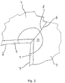
- Fig. 2 The end edges 6 and the first edge 7 of two sheet elements 3, 4 joined together in a joint 8 is seen in Fig. 2 in detail.
- Fig. 2 also shows the mounting means 9, which are provided along the first edges 7 of the sheet elements 3, 4.
- a reinforcement element 10 is provided at the joint 8.
- the reinforcement element 10 covers part of the joint 8 and part of joined sheet elements 3, 4 in an area adjacent to the joint 8 and extending from the first edges 7 of the joined sheet elements 3, 4. Even though the area in the shown example is circular, other shapes of the area could be envisaged.
- the mounting means are, in the example depicted in Fig. 2 , formed by a strip element 9 attached to each sheet element prior to the joining of the sheet elements.
- Each strip 9 is extending uninterruptedly along the entire length of the first edge 7 of each sheet element and adjacent strips 9 are joined in the joints 8 along with their respective sheet elements.
- the collar-shaped vapour barrier collar has uninterrupted mounting means along its entire rim along the first edges of the sheet elements.
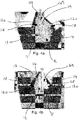
- FIG. 3a shows a section of an example of the vapour barrier collar 1 including a sheet element 3 and mounting means in the form of a strip element 9 attached thereto.
- the strip element 9 is extruded from a plastics material, such as polyethylene.
- the strip 9 has two opposite faces 17 extending between two relatively short end faces 18.
- the sheet element 3 is attached to the strip 9 at one of the faces 17 by welding, gluing, heat sealing or any other suitable process.
- a welding seam 11 is indicated.
- the strip 9 may be attached to the sheet element 3 along a central part of the strip 9, leaving the parts adjacent to the central part unattached as illustrated in Fig. 3a . This may yield a more flexible strip.
- the strip may be attached to the sheet element over its entire surface.
- Fig. 3b shows the section of the example of the vapour barrier collar 1 from Fig. 3a , now mounted in a groove 12.
- the groove 12 represents a groove such as the one surrounding an aperture of a building structure, for instance the groove (not clearly discernible) surrounding the roof window aperture 16 in Fig. 1 .
- the groove 12 has two sidewalls 13, 14 extending substantially perpendicular to a bottom wall 15.
- the strip 9 is inserted into the groove 12 so that the face 17 of the strip 9, opposite the face 17 attached to a sheet element 3, abuts the bottom wall 15 of the groove 12.
- the two short end faces 18 of the strip 9 abut each their sidewall 13, 14 of the groove 12. 18.
- the mounting means of the vapour barrier collar may be brought to abut at least one side face of the circumferential groove, or at least one side face and the bottom face of the circumferential groove.
- the strip 9 is somewhat over-dimensioned in relation to the width of the groove 12 so that the strip 9 is slightly deformed when inserted into the groove 12. Thereby a good sealing effect is obtained, and also a good securing of the strip 9 and thus of the entire vapour barrier collar 1 in the groove 12.
- the strip 9 may be substantially plane as shown.
- the thickness of the strip 9 is preferably in the range of approximately 0.5-5 mm, more preferably in the range of approximately 1-3 mm, and most preferably approximately 2 mm.
- the strip may vary in thickness from one end face 18 to the other.
- the strip may have a larger thickness proximal to the end faces in proportion to the thickness of the central part of the strip, or vice versa, the thickness of the central part of the strip may be larger in proportion to the thickness proximal to the end faces, which in this latter case ultimately may be reduced to lines.
- the strip element it comprises more than one component.
- Figs 4a-b show an example of a strip 109 comprising a first component 119 and a second component 120.
- the strip 109 has the same overall structure as described above, i.e. with two opposite faces 117 extending between two relatively short end faces 118, all of which extend in a direction along a longitudinal axis LS of the strip 109. Also, the same considerations as above regarding thickness and possible variation of thickness from one end face 118 to the other apply.
- a sheet element (not shown) is to be attached to the strip 109 at the face 117 facing away from the groove 12 in a manner and to an extent as described above.
- Each of the components 119, 120 extends in a direction along the longitudinal axis LS of the strip 109, the second component 120 being located primarily in zones proximal to the two end faces 118, while the first component 119 is primarily located in a zone extending between the zones of the second component 120.
- the zones of the second component 120 preferably constitute 5-60 % of the cross sectional area, more preferably 10-40 % and most preferably 20-30 %.
- the first component 119 is preferably extruded from a plastics material, such as polyethylene.
- the second component 120 is preferably made of a more flexible material in comparison with the material of the first component 119, such as for instance Santoprene®.
- the relatively stiff first component 119 provides stiffness and stability to the strip 109, while the relatively flexible second component yields good sealing capability and also a good securing of the strip 109 in the groove 12. This may best be seen from Fig. 4b showing the strip element 109 in a fully mounted position with the zones of the second component 120 abutting the sidewalls 13, 14 of the groove 12.
- the mounting means are an integrated part of each sheet element formed by a folded or rolled up part of each sheet element.
- the folded or rolled up part of the sheet element may be fixed in its folded or rolled up condition by any suitable process such as for instance welding, gluing or heat sealing.
- vapour barrier collar fitting a rectangular aperture of a roof-penetrating building structure
- other geometrical configurations are conceivable.
- sheet elements and/or sheet elements of alternative shapes to be joined to form a vapour barrier collar of a shape other than rectangular.
- a vapour barrier collar fitting a semicircular window aperture could be envisaged.
- the vapour barrier collar may be applied for surrounding different types of apertures of roof-penetrating building structures, such as roof windows, windows, doors, escape ways, ventilation ducts etc.
- the tool 50 comprises insertion means 51 for introducing mounting means of the vapour barrier collar into a groove adapted to receive said mounting means, and operating means 53 for operating the tool 50.
- the insertion means 51 comprise a face 52 for applying a pressure on the mounting means and are connected to the operating means 53 in a region of contact at a first end 56 of the insertion means 51.
- the face 52 of the insertion means 51 is convexly curved around an axis running parallel to the width wf of the face 52.
- the radius of curvature is constant and approximately amounts 150 mm.
- the radius of curvature may be constant or vary and preferably lies in the area between 50-300 mm, more preferably between 100-200 mm. Alternatively, a completely flat face may be envisaged.
- the width wf of the face 52 it is expedient that it is slightly smaller than the distance between the two sidewalls of the groove into which the mounting means of the vapour barrier collar is to be inserted. In the shown embodiment, the width wf is approximately 8 mm. The width wf generally preferably lies between 3-15 mm.
- the operating means 53 of the shown embodiment of the tool 50 comprise an oblong cavity 54 and an opening 55 towards the ambient in connection with the cavity 54.
- the cavity 54 is able to receive at least partially and retain a correspondingly oblong object, such as a carpenter's pencil (as shown in Fig 5b ).
- a correspondingly oblong object such as a carpenter's pencil (as shown in Fig 5b ).
- oblong is understood that the dimension of the cavity 54 in a longitudinal direction is at least slightly larger than the dimension of the cavity 54 in a transversal direction. In this particular embodiment, the dimension of the cavity 54 in a longitudinal direction is approximately 1.5 times larger than the dimension of the cavity 54 in a transversal direction.
- This is a preferred dimensioning of the cavity as a carpenter's pencil will most often into a cavity of this size thus serving as a handle as it prolongs the operating means of the tool 50.
- Different cross sectional shapes may be envisaged besides rectangular, for instance square, oval, elliptic or round.
- the dimension of the operating means in the longitudinal direction must in this case be of a size permitting the operating means to be used as handle, i.e. the operating means preferably have a dimension in the longitudinal direction of 15 mm.
- the dimension of the operating means in the longitudinal direction in this embodiment lies between 10-20 mm.
- the insertion me ans 51 approaches the operating means 53 in a distance from the connection point between the insertion means 51 and the operating means 53 thus forming a pen clip-like structure 58. The distance preferably lies in the range of 3-7 mm.
- the insertion means 51 may abut the operating means 53.
- the mounting means 9 of the vapour barrier collar 1 is successively introduced into the circumferential groove 12 of a building structure by applying a pressure on the mounting means 9 by the aid of the tool 50 while carrying out a sliding movement of said tool 50 upon the mounting means 9 in a direction parallel to the first edge 7 of each sheet element 2, 3, 4, 5.
- the face 52 of the insertion means 51 of the tool 50 faces the mounting means 9 of the vapour barrier collar 1. Since the mounting means 9, as explained above, are somewhat over-dimensioned in relation to the width of the groove 12, the mounting means 9 are successively secured well in the groove 12 and stays there while the tool is slid further on upon the mounting means.
- the above mentioned guide holes preferably going through both sheet elements 2, 3, 4, 5 and mounting means 9 may serve an additional purpose in relation to mounting the vapour barrier collar 1 in a groove.
- the guide holes are namely of a size to permit the body of a typical size screw for this purpose to pass through the guide hole, while the head of the screw will be retained by the guide hole.
- the guide hole intended to receive a mounting screw may be marked in any suitable manner, for instance by a colour marking, a different size or the like. This way, even though not necessary, screws may be utilized for securing the mounting of the vapour barrier to an extra degree by aid of screws.
Landscapes
- Engineering & Computer Science (AREA)
- Architecture (AREA)
- Civil Engineering (AREA)
- Structural Engineering (AREA)
- Mechanical Engineering (AREA)
- Building Environments (AREA)
- Greenhouses (AREA)
- Tents Or Canopies (AREA)
- Laminated Bodies (AREA)
- Absorbent Articles And Supports Therefor (AREA)
- Roof Covering Using Slabs Or Stiff Sheets (AREA)
- Lining Or Joining Of Plastics Or The Like (AREA)
- Connection Of Plates (AREA)
- Jigs For Machine Tools (AREA)
Description
- The present invention relates to a kit comprising a tool for use in mounting a vapour barrier collar and a vapour barrier collar, the vapour barrier collar comprising a number of sheet elements including side sheet elements extending substantially along a longitudinal axis and top and bottom sheet elements, respectively, extending substantially along a lateral axis perpendicular to said longitudinal axis, each sheet element having two end edges adjacent to a first edge of said sheet element, said sheet elements being mutually joined together in joints extending along said end edges, and mounting means are being provided along said first edges of said sheet elements, said mounting means extending uninterruptedly along the entire length of said first edge of each sheet element. The invention furthermore relates to method for mounting a vapour barrier collar utilizing such a kit.
- A vapour barrier collar is for instance known from the European patent
EP 0 994 991 . Such a vapour barrier collar is adapted to be mounted along the circumference of an aperture in a roof-penetrating building structure, such as an aperture of a window frame. The building structure may be any kind of roof-penetrating building structure, such as a roof window or a skylight. - The mounting takes place by inserting the mounting means of the vapour barrier collar in a circumferential groove surrounding the aperture. The mounting means are in the form of a number of individual "press-in pieces" of a relatively stiffer material compared to the vapour barrier collar material, the press-in pieces being distributed with intervals along the edge of the collar that is to be inserted into the groove of the building structure. However, to ensure a reliable and sealing mounting of the vapour barrier collar in the groove, use of additional mounting means is necessary. For this purpose, i.a. strips of butyl rubber is inserted in the groove of the building structure prior to inserting the press-in pieces of the vapour barrier collar. In order to ensure a sufficient degree of sealing against heat loss, condensation and vapour, great care must be taken when inserting the strips of butyl rubber. As it is time consuming and difficult to place the butyl strip correctly it is hard to obtain a sufficient degree of sealing.
- Furthermore, often the butyl rubber strips simply let go of the groove e.g. due to dust, wet spots etc. For this reason, screws are used to secure the mounting means in the groove on top of the butyl rubber strips. Thus, the amount of time required to mount a vapour barrier collar is relatively extensive.
- In the case of for instance a roof window, the lining, which is inserted in the groove subsequently to the mounting of the vapour barrier collar, assists in providing the sealing effect by squeezing the butyl rubber strips and mounting means to abut the walls of the groove closely. For this reason, the lining must be mounted with great care too. Often, the lining, which is used, is of a different brand than the vapour barrier collar and/or the groove and may thus not fit perfectly. This increases the risk of an unsatisfactory sealing.
- A further example of a tool in the prior art is represented by
WO 01/74540 A1 US patent No. 4,572,688 . - However, while the equipment of the prior art is suitable for the respective field of application, there still exists a need for a kit including a tool which facilitates the mounting of a vapour barrier collar.
- In a first aspect of the invention, a kit comprising a tool and a vapour barrier collar according to the present invention is provided. The tool comprises insertion means for introducing the mounting means of the vapour barrier collar into a groove adapted to receive said mounting means, and operating means for operating the tool, where the insertion means comprise a face for applying a pressure and gliding on the mounting means and is connected to the operating means in at least one connection point. The insertion means approach and/or abut the operating means in a distance from the connection point between the insertion means and the operating means thus forming a pen clip-like structure. This way multiple functionalities are provided in a very compact manner: An ability to park the tool and any e.g. pencil or pen partly received in it by the pen clip-like structure is obtained, while the face of the pen clip-like structure serves as insertion means when in use for mounting. Furthermore, great robustness of the insertion means is obtained as the operating means serve as support for the end of the insertion means being in a distance from the connection point.
- In one embodiment, the operating means of the tool comprise an oblong cavity and an opening towards the ambient in connection with the cavity, which is able to receive at least partially and retain an object, such as a carpenter's pencil. "Oblong" means that the dimension of the cavity in a longitudinal direction is at least slightly larger than the dimension of the cavity in a transversal direction. In this way, the object, for instance a carpenter's pencil, serves as a handle as it prolongs the operating means of the tool when partly contained in the cavity. This provides for a tool that is always at hand. As the tool can be removed from the carpenter's pencil when not in use the tool is very little space consuming due to its compact structure.
- In one embodiment of the tool, the operating means are oblong so as to serve as a handle. Again, "oblong" means that the dimension of the operating means in a longitudinal direction is at least slightly larger than the dimension of the operating means in a transversal direction. Preferably, the dimension of the operating means in the longitudinal direction is of a size permitting the operating means to be used as handle. This configuration makes it possible to operate the tool independently of the presence of for instance a carpenter's pencil.
- In a second aspect of the invention, a method for mounting a vapour barrier collar utilizing such a kit is provided.
- Further embodiments, examples and advantages will appear from the following, where some exemplary embodiments of the present invention will be described in further detail, some with reference to the accompanying schematic drawings, where:
-
Fig. 1 is a front view of a vapour barrier collar in a mounted condition, surrounding an aperture of a roof-penetrating building structure, -
Fig. 2 shows a section of a vapour barrier collar, more specifically an area adjacent a joint, -
Fig. 3a shows another section of a vapour barrier collar, including mounting means, -
Fig. 3b shows the section ofFig. 3a in a mounted position, and -
Fig. 3c is a detail ofFig. 3b on a larger scale, -
Fig. 4a shows a section of an example of mounting means for a vapour barrier collar in a partially mounted condition, -
Fig. 4b shows the section of the example of the mounting means ofFig. 4a in a fully mounted position, -
Fig. 5a is a perspective view of an embodiment of a tool forming part of a kit according to the invention for use in mounting a vapour barrier, and -
Fig. 5b is a perspective view of the tool offig. 5b seen from a different angle and with a carpenter's pencil inserted. -
Fig. 1 is a schematic front view of a vapour barrier collar generally designated 1 in an example. The vapour barrier collar 1 comprises a number ofsheet elements top sheet element 4 and a bottom sheet element 5 are provided. Theside sheet elements 2, 3 extend in a direction along a longitudinal central axis L, and the top and bottom sheet elements, respectively, extend in a direction along a lateral central axis A perpendicular to the longitudinal axis L. The roof-penetrating building structure is in the following referred to as window 16a, and the aperture of thewindow 16 is referred to asaperture 16. - The vapour barrier collar 1 is intended to be connected to a
vapour barrier membrane 40 of an underroof forming part of an overall roof structure. The underroof is arranged essentially betweenrafters 20 and with an inner cladding (not shown) in the form of a board layer or panels fastened to the inner side of therafters 20, thevapour barrier membrane 40, which may be produced by plastic foil, aluminium foil, kraft paper or laminates hereof, an isolation layer (not shown), the outside of which is arranged at a distance below the outside of therafters 20 in order to provide ventilation, and an outer cladding (not shown), on the outside of which a (not shown) weather-shielding outer membrane is positioned and to which is fastened an arrangement of counter battens andbattens 30 as a support for a (not shown) outer roofing, which can consist of tiles or slates. In this manner a vapour-proof transition between the roof window 16a and thevapour barrier membrane 40 of the underroof is obtained. - The vapour barrier collar 1 is, in the example shown, substantially symmetrical about both the longitudinal central axis L and the lateral central axis A. Due to this symmetry, it is understood that the description applies for all sections of the vapour barrier collar 1 though only one section of the vapour barrier collar 1 is described.
- In one example the vapour barrier collar is composed of four
trapezoidal sheet elements EP 0 994 991 . - Each
sheet element end edges 6 adjacent to afirst edge 7. Adjacent sheet elements are mutually joined together injoints 8 extending along the end edges 6. In this manner, the vapour barrier collar forms a collar including a coherent rim along the first edges of the respective sheet elements. - In one example, the
sheet elements first edge 7 and eachend edge 6, respectively, of asheet element first edge 7 and eachrespective end edge 6 lies in the interval between 90° and 180°, however preferably between 95° and 175°, and more preferably between 110° and 130°. The vapour barrier collar 1 is thus applicable in connection with roof pitches lying in the interval between 5° and 85°, however preferably between 15° and 60°. - In the example shown, as is best seen on
fig. 2 , the orientation of the projection of the joint 8's direction on the mounting means plane is 45° in relation to the production of thefirst edge 9 of thesheet element 3 extending in the longitudinal direction L. Similarly, although not interpretable fromfig. 2 , the orientation of the projection of the joint 8's direction on the plane extending in the longitudinal direction L of the vapour barrier 1 perpendicular to the mounting means plane is 30° in relation to the production of thefirst edge 9 of thesheet element 3 extending in the longitudinal direction L. However, different angles may apply to different applications, one example being described in further detail below. - The end edges 6 and the
first edge 7 of twosheet elements Fig. 2 in detail.Fig. 2 also shows the mounting means 9, which are provided along thefirst edges 7 of thesheet elements reinforcement element 10 is provided at thejoint 8. Thereinforcement element 10 covers part of the joint 8 and part of joinedsheet elements first edges 7 of the joinedsheet elements - Prior to joining of neighbouring
sheet elements sheet elements sheets - When joining together
sheet elements sheet elements sheet elements - As regards the mounting means, they are, in the example depicted in
Fig. 2 , formed by astrip element 9 attached to each sheet element prior to the joining of the sheet elements. Eachstrip 9 is extending uninterruptedly along the entire length of thefirst edge 7 of each sheet element andadjacent strips 9 are joined in thejoints 8 along with their respective sheet elements. In this manner, the collar-shaped vapour barrier collar has uninterrupted mounting means along its entire rim along the first edges of the sheet elements. - Referring now to
Figs 3a-c , the mounting means 9 will be described in further detail.Fig. 3a shows a section of an example of the vapour barrier collar 1 including asheet element 3 and mounting means in the form of astrip element 9 attached thereto. Thestrip element 9 is extruded from a plastics material, such as polyethylene. Thestrip 9 has two opposite faces 17 extending between two relatively short end faces 18. Thesheet element 3 is attached to thestrip 9 at one of the faces 17 by welding, gluing, heat sealing or any other suitable process. OnFig. 3a , a welding seam 11 is indicated. Thestrip 9 may be attached to thesheet element 3 along a central part of thestrip 9, leaving the parts adjacent to the central part unattached as illustrated inFig. 3a . This may yield a more flexible strip. Alternatively, the strip may be attached to the sheet element over its entire surface. -
Fig. 3b shows the section of the example of the vapour barrier collar 1 fromFig. 3a , now mounted in agroove 12. Thegroove 12 represents a groove such as the one surrounding an aperture of a building structure, for instance the groove (not clearly discernible) surrounding theroof window aperture 16 inFig. 1 . Thegroove 12 has twosidewalls bottom wall 15. Thestrip 9 is inserted into thegroove 12 so that the face 17 of thestrip 9, opposite the face 17 attached to asheet element 3, abuts thebottom wall 15 of thegroove 12. Also, the two short end faces 18 of thestrip 9 abut each theirsidewall groove 12. 18. In principle, the mounting means of the vapour barrier collar may be brought to abut at least one side face of the circumferential groove, or at least one side face and the bottom face of the circumferential groove. - As is best seen from
Fig. 3c , thestrip 9 is somewhat over-dimensioned in relation to the width of thegroove 12 so that thestrip 9 is slightly deformed when inserted into thegroove 12. Thereby a good sealing effect is obtained, and also a good securing of thestrip 9 and thus of the entire vapour barrier collar 1 in thegroove 12. - The
strip 9 may be substantially plane as shown. The thickness of thestrip 9 is preferably in the range of approximately 0.5-5 mm, more preferably in the range of approximately 1-3 mm, and most preferably approximately 2 mm. Alternatively, the strip may vary in thickness from oneend face 18 to the other. For instance, the strip may have a larger thickness proximal to the end faces in proportion to the thickness of the central part of the strip, or vice versa, the thickness of the central part of the strip may be larger in proportion to the thickness proximal to the end faces, which in this latter case ultimately may be reduced to lines. - In one example of the strip element, it comprises more than one component.
Figs 4a-b show an example of astrip 109 comprising afirst component 119 and asecond component 120. Thestrip 109 has the same overall structure as described above, i.e. with twoopposite faces 117 extending between two relatively short end faces 118, all of which extend in a direction along a longitudinal axis LS of thestrip 109. Also, the same considerations as above regarding thickness and possible variation of thickness from oneend face 118 to the other apply. A sheet element (not shown) is to be attached to thestrip 109 at theface 117 facing away from thegroove 12 in a manner and to an extent as described above. - Each of the
components strip 109, thesecond component 120 being located primarily in zones proximal to the two end faces 118, while thefirst component 119 is primarily located in a zone extending between the zones of thesecond component 120. - Considering the cross sectional area of the
strip 109 perpendicular to its longitudinal axis LS, the zones of thesecond component 120 preferably constitute 5-60 % of the cross sectional area, more preferably 10-40 % and most preferably 20-30 %. - The
first component 119 is preferably extruded from a plastics material, such as polyethylene. Thesecond component 120 is preferably made of a more flexible material in comparison with the material of thefirst component 119, such as for instance Santoprene®. Thus, the relatively stifffirst component 119 provides stiffness and stability to thestrip 109, while the relatively flexible second component yields good sealing capability and also a good securing of thestrip 109 in thegroove 12. This may best be seen fromFig. 4b showing thestrip element 109 in a fully mounted position with the zones of thesecond component 120 abutting thesidewalls groove 12. - Of course, other structures of the
strip 109 may be envisaged, for instance, a strip with one or more additional zones ofsecond component 120 running along the central part of the strip intended to face thebottom wall 15 of thegroove 12, thus providing an extra sealing effect. In a further, not-shown, example the mounting means are an integrated part of each sheet element formed by a folded or rolled up part of each sheet element. The folded or rolled up part of the sheet element may be fixed in its folded or rolled up condition by any suitable process such as for instance welding, gluing or heat sealing. The observations stated above in relation to the strip-type mounting means also apply to this integrated, folded or rolled up-type mounting means as regards dimensions, cross sectional shape, attachment etc. - It is understood that the invention is not limited to the embodiments described and/or shown in the above, but various modifications and combinations may be carried out without departing from the scope of the claims.
- Although the joined side, top and bottom sheet elements in the example shown and described in the above form a vapour barrier collar fitting a rectangular aperture of a roof-penetrating building structure, other geometrical configurations are conceivable. For instance, there may be provided any number of sheet elements and/or sheet elements of alternative shapes to be joined to form a vapour barrier collar of a shape other than rectangular. For instance, a vapour barrier collar fitting a semicircular window aperture could be envisaged. Also, the vapour barrier collar may be applied for surrounding different types of apertures of roof-penetrating building structures, such as roof windows, windows, doors, escape ways, ventilation ducts etc.
- Now referring to the
Figs 5a-b , a tool according to the present invention for use in mounting a vapour barrier collar will be described in further detail. The tool is applicable for use in mounting a vapour barrier collar whether formed by 1) four trapezoidal sheet elements, 2) two trapezoidal sheet elements and two rectangular sheet elements as the prior art vapour barrier collar described inEP 0 994 991 , or 3) any other shape as described in the foregoing paragraph. In the embodiment shown, thetool 50 comprises insertion means 51 for introducing mounting means of the vapour barrier collar into a groove adapted to receive said mounting means, and operating means 53 for operating thetool 50. The insertion means 51 comprise aface 52 for applying a pressure on the mounting means and are connected to the operating means 53 in a region of contact at afirst end 56 of the insertion means 51. - The
face 52 of the insertion means 51 is convexly curved around an axis running parallel to the width wf of theface 52. The radius of curvature is constant and approximately amounts 150 mm. The radius of curvature may be constant or vary and preferably lies in the area between 50-300 mm, more preferably between 100-200 mm. Alternatively, a completely flat face may be envisaged. - As regards the width wf of the
face 52, it is expedient that it is slightly smaller than the distance between the two sidewalls of the groove into which the mounting means of the vapour barrier collar is to be inserted. In the shown embodiment, the width wf is approximately 8 mm. The width wf generally preferably lies between 3-15 mm. - The operating means 53 of the shown embodiment of the
tool 50 comprise anoblong cavity 54 and anopening 55 towards the ambient in connection with thecavity 54. Thecavity 54 is able to receive at least partially and retain a correspondingly oblong object, such as a carpenter's pencil (as shown inFig 5b ). As explained above, by "oblong" is understood that the dimension of thecavity 54 in a longitudinal direction is at least slightly larger than the dimension of thecavity 54 in a transversal direction. In this particular embodiment, the dimension of thecavity 54 in a longitudinal direction is approximately 1.5 times larger than the dimension of thecavity 54 in a transversal direction. This is a preferred dimensioning of the cavity as a carpenter's pencil will most often into a cavity of this size thus serving as a handle as it prolongs the operating means of thetool 50. Different cross sectional shapes may be envisaged besides rectangular, for instance square, oval, elliptic or round. - In the case where the operating means of the tool are oblong so as to serve as a handle them selves, the same considerations as above regarding "oblong" apply. However, the dimension of the operating means in the longitudinal direction must in this case be of a size permitting the operating means to be used as handle, i.e. the operating means preferably have a dimension in the longitudinal direction of 15 mm. Preferably, the dimension of the operating means in the longitudinal direction in this embodiment lies between 10-20 mm. In the depicted embodiment, the insertion me ans 51 approaches the operating means 53 in a distance from the connection point between the insertion means 51 and the operating means 53 thus forming a pen clip-
like structure 58. The distance preferably lies in the range of 3-7 mm. The insertion means 51 may abut the operating means 53. - It the following, it will be explained how the
tool 50 is utilized in mounting the vapour barrier collar 1 in a roof-penetrating building structure. The mounting means 9 of the vapour barrier collar 1 is successively introduced into thecircumferential groove 12 of a building structure by applying a pressure on the mounting means 9 by the aid of thetool 50 while carrying out a sliding movement of saidtool 50 upon the mounting means 9 in a direction parallel to thefirst edge 7 of eachsheet element face 52 of the insertion means 51 of thetool 50 faces the mounting means 9 of the vapour barrier collar 1. Since the mounting means 9, as explained above, are somewhat over-dimensioned in relation to the width of thegroove 12, the mounting means 9 are successively secured well in thegroove 12 and stays there while the tool is slid further on upon the mounting means. - Optionally, the above mentioned guide holes preferably going through both
sheet elements - The invention is not delimited to the embodiments described in the above and shown in the drawings but various modifications and combinations may be carried out without departing from the scope of the claims.
Claims (5)
- Kit comprising a tool (50) for use in mounting a vapour barrier collar (1) and a vapour barrier collar,
the vapour barrier collar comprising a number of sheet elements (2, 3, 4, 5) including side sheet elements (2, 3) extending substantially along a longitudinal axis (L) and top (4) and bottom (5) sheet elements, respectively, extending substantially along a lateral axis (A) perpendicular to said longitudinal axis (L), each sheet element (2, 3, 4, 5) having two end edges (6) adjacent to a first edge (7) of said sheet element, said sheet elements being mutually joined together in joints (8) extending along said end edges (6), and mounting means (9) being provided along said first edges (7) of said sheet elements, said mounting means (9) extending uninterruptedly along the entire length of said first edge (7) of each sheet element (2, 3, 4, 5),
said tool (50) comprising insertion means (51) for introducing the mounting means (9) of said vapour barrier collar (1) into a groove (12) adapted to receive said mounting means (9), and
operating means (53) for operating the tool, where said insertion means (51) comprise a face (52) for applying a pressure and gliding on said mounting means (9) and is connected to said operating means (53) in at least one connection point,
where said insertion means (51) approach and/or abut said operating means (53) in a distance from said connection point between said insertion means (51) and said operating means (53) thus forming a pen clip-like structure (58). - Kit according to claim 1, where said operating means (53) comprise an oblong cavity (54) and an opening (55) towards the ambient in connection with said cavity (54), which is able to receive at least partially and retain a correspondingly oblong object, such as a carpenter's pencil.
- Kit according to any of the claims 1 and 2, where said operating means (53) are oblong so as to serve as a handle.
- Method for mounting a vapour barrier collar (1) utilizing a kit according to any of the claims 1 to 3,
the method comprising the step of:introducing successively the mounting means (9) of said vapour barrier collar (1) into a circumferential groove (12) of a building structure, wheresaid introduction takes place by applying a pressure on the mounting means (9) by means of the tool (50) while carrying out a sliding movement of said tool (50) upon the mounting means (9) in a direction parallel to the first edge (7) of each sheet element (2, 3, 4, 5),wherein the groove (12) comprises sidewalls, and a bottom wall, and the method comprising the step of bringing the mounting means (9) to abut at least one sidewall and the bottom wall (9) of the circumferential groove (12). - Method according to claim 4,
wherein the vapour barrier collar (1) comprises guide holes provided in the sheet elements (2, 3, 4, 5) and/or the mounting means (9),
the method comprises the step of utilizing additional mounting means, so as for instance screws, in connection with said guide holes provided in said sheet elements (2, 3, 4, 5) and/or mounting means (9).
Priority Applications (1)
| Application Number | Priority Date | Filing Date | Title |
|---|---|---|---|
| PL13190214T PL2711480T3 (en) | 2009-03-17 | 2010-03-04 | A tool for use in mounting a vapour barrier collar and a method for mounting a vapour barrier collar |
Applications Claiming Priority (2)
| Application Number | Priority Date | Filing Date | Title |
|---|---|---|---|
| DKPA200900374A DK177565B1 (en) | 2009-03-17 | 2009-03-17 | Vapour barrier collar, method for producing a vapour barrier collar and method for mounting a vapour barrier collar |
| EP10155419.4A EP2243893B1 (en) | 2009-03-17 | 2010-03-04 | Vapour barrier collar, method for producing a vapour barrier collar |
Related Parent Applications (2)
| Application Number | Title | Priority Date | Filing Date |
|---|---|---|---|
| EP10155419.4A Division-Into EP2243893B1 (en) | 2009-03-17 | 2010-03-04 | Vapour barrier collar, method for producing a vapour barrier collar |
| EP10155419.4A Division EP2243893B1 (en) | 2009-03-17 | 2010-03-04 | Vapour barrier collar, method for producing a vapour barrier collar |
Publications (3)
| Publication Number | Publication Date |
|---|---|
| EP2711480A2 EP2711480A2 (en) | 2014-03-26 |
| EP2711480A3 EP2711480A3 (en) | 2017-11-08 |
| EP2711480B1 true EP2711480B1 (en) | 2020-01-22 |
Family
ID=42182079
Family Applications (2)
| Application Number | Title | Priority Date | Filing Date |
|---|---|---|---|
| EP13190214.0A Active EP2711480B1 (en) | 2009-03-17 | 2010-03-04 | A tool for use in mounting a vapour barrier collar and a method for mounting a vapour barrier collar |
| EP10155419.4A Active EP2243893B1 (en) | 2009-03-17 | 2010-03-04 | Vapour barrier collar, method for producing a vapour barrier collar |
Family Applications After (1)
| Application Number | Title | Priority Date | Filing Date |
|---|---|---|---|
| EP10155419.4A Active EP2243893B1 (en) | 2009-03-17 | 2010-03-04 | Vapour barrier collar, method for producing a vapour barrier collar |
Country Status (11)
| Country | Link |
|---|---|
| US (1) | US8900684B2 (en) |
| EP (2) | EP2711480B1 (en) |
| JP (1) | JP5683823B2 (en) |
| CN (2) | CN101839043B (en) |
| DE (1) | DE202010018125U1 (en) |
| DK (2) | DK177565B1 (en) |
| EA (1) | EA024874B1 (en) |
| ES (1) | ES2599655T3 (en) |
| HU (1) | HUE032070T2 (en) |
| LT (1) | LT2243893T (en) |
| PL (2) | PL2711480T3 (en) |
Cited By (1)
| Publication number | Priority date | Publication date | Assignee | Title |
|---|---|---|---|---|
| DE202021102160U1 (en) | 2020-04-22 | 2021-08-16 | Vkr Holding A/S | A tool for use in installing a vapor barrier apron and further comprising a knife tool |
Families Citing this family (5)
| Publication number | Priority date | Publication date | Assignee | Title |
|---|---|---|---|---|
| WO2015081012A1 (en) * | 2013-11-27 | 2015-06-04 | Bluescope Buildings North America Inc. | Metal roof penetration thermal break |
| EP4219855A1 (en) | 2018-06-28 | 2023-08-02 | VKR Holding A/S | Plaster board support bracket |
| CN109822502B (en) * | 2019-03-25 | 2024-01-23 | 苏州盛贸汽车部件有限公司 | Automatic spin riveting device of automobile skylight mechanical group and spin riveting method using same |
| DE102019002839B4 (en) * | 2019-04-18 | 2021-10-14 | Manriko Pust | Extension for pens with leads that wear out |
| CN112776921B (en) * | 2021-03-16 | 2022-05-03 | 奇瑞汽车股份有限公司 | Special auxiliary tool and method for mounting panoramic sunroof of automobile |
Citations (1)
| Publication number | Priority date | Publication date | Assignee | Title |
|---|---|---|---|---|
| US4572688A (en) * | 1982-07-16 | 1986-02-25 | Prasenta Kg Weber & Co. | Ball-point pen |
Family Cites Families (28)
| Publication number | Priority date | Publication date | Assignee | Title |
|---|---|---|---|---|
| JPS5416502Y2 (en) | 1974-04-30 | 1979-06-28 | ||
| US4341007A (en) * | 1977-05-18 | 1982-07-27 | General Electric Company | Method of roller inserting filler material in crevices |
| DE2728836A1 (en) * | 1977-06-27 | 1979-01-18 | Graeff Roderich Wilhelm | Skylight or roof solar energy panel frame sealant - comprises monolithic flexible weatherproof unit, foldable for transport |
| DE2910610A1 (en) * | 1979-03-17 | 1980-09-18 | Ludwig Vetter | Pitched roof chimney retention and strengthening - involves additional plate overlapping top corner piece shanks, with sealing device |
| US4336706A (en) | 1980-05-15 | 1982-06-29 | Garcia Alberto A | Lathekin |
| DE3442276A1 (en) * | 1983-12-09 | 1985-06-13 | Peter W. 7290 Freudenstadt Barth | Securing means for beneath-roof windows |
| US5211506A (en) * | 1990-10-11 | 1993-05-18 | William Manion | Backer rod or bond breaker corrective placement tools |
| JPH05137817A (en) | 1991-11-20 | 1993-06-01 | Sumitomo Rubber Ind Ltd | Spherical material molding metal mold and golf ball molded by the same |
| DE9413970U1 (en) | 1994-08-29 | 1996-01-04 | Klöber, Johannes, 58256 Ennepetal | Sealing device |
| DE19514150C2 (en) | 1995-04-15 | 1997-05-28 | Braas Gmbh | Kit for a connection lining for a window frame |
| US5829221A (en) * | 1997-03-10 | 1998-11-03 | Archuleta; Rick A. | Roofing tool |
| DK173990B1 (en) * | 1997-07-09 | 2002-03-25 | Vkr Holding As | Skylight window with connection collar for a vapor barrier membrane |
| DE29822547U1 (en) | 1998-12-18 | 1999-02-25 | Pelikan Gmbh, 30177 Hannover | Cap for a hand-held writing instrument |
| JP2000257221A (en) * | 1999-01-01 | 2000-09-19 | Gantan Beauty Ind Co Ltd | Roof structure with inner gutter |
| DK200000108U3 (en) * | 2000-03-24 | 2000-07-28 | Niels Joergen Larsen | Tools for use in grouting |
| US6354046B1 (en) * | 2000-07-29 | 2002-03-12 | Michael R Swearingen | Skylight membrane with diverter |
| DE10057774A1 (en) * | 2000-11-22 | 2002-10-10 | Kloeber Johannes | Flashing skirt for e.g. chimney penetration through pitched roof, is pleated using series of opposed dovetail folds |
| JP2002205551A (en) * | 2001-01-10 | 2002-07-23 | Honda Motor Co Ltd | Method of fitting seal rubber for sash frame of vehicle door and fitting jig thereof |
| JP2003119971A (en) | 2001-10-18 | 2003-04-23 | Ube Kimitsu Housing Kk | Draining waterproof sheet for roof window |
| US20060117699A1 (en) * | 2002-07-10 | 2006-06-08 | Agostino Di Trapani | Building block |
| US6681613B1 (en) * | 2003-02-24 | 2004-01-27 | Jody English | Chimney flashing fabrication tool |
| US7591106B2 (en) * | 2003-12-19 | 2009-09-22 | Marvin Lumber And Cedar Company | Flashing assembly |
| CN2787805Y (en) * | 2004-06-30 | 2006-06-14 | Vkr控股公司 | Sealing collar |
| PL216384B1 (en) * | 2005-06-08 | 2014-03-31 | Fakro Pp Społka Z Ograniczoną Odpowiedzialnością | Flange that joins the building structure, passing through the roof surface to the structure under the roofing |
| US7754304B1 (en) * | 2005-12-27 | 2010-07-13 | Mitek Holdings, Inc. | Weatherproofing backer for window and door installation |
| US8096088B2 (en) * | 2006-10-19 | 2012-01-17 | Tremco Incorporated | Glazing assembly for rough openings |
| CN200974220Y (en) * | 2006-11-14 | 2007-11-14 | 中国南车集团株洲电力机车有限公司 | Mounting jig for locomotive or vehicle rubber layering core |
| CN201353751Y (en) * | 2008-12-19 | 2009-12-02 | 博西威家用电器有限公司 | Mounting tool of gland strip |
-
2009
- 2009-03-17 DK DKPA200900374A patent/DK177565B1/en active
-
2010
- 2010-03-04 DE DE201020018125 patent/DE202010018125U1/en not_active Expired - Lifetime
- 2010-03-04 LT LTEP10155419.4T patent/LT2243893T/en unknown
- 2010-03-04 EP EP13190214.0A patent/EP2711480B1/en active Active
- 2010-03-04 ES ES10155419.4T patent/ES2599655T3/en active Active
- 2010-03-04 PL PL13190214T patent/PL2711480T3/en unknown
- 2010-03-04 PL PL10155419T patent/PL2243893T3/en unknown
- 2010-03-04 HU HUE10155419A patent/HUE032070T2/en unknown
- 2010-03-04 EP EP10155419.4A patent/EP2243893B1/en active Active
- 2010-03-09 US US12/659,417 patent/US8900684B2/en not_active Expired - Fee Related
- 2010-03-16 CN CN201010134512.9A patent/CN101839043B/en active Active
- 2010-03-16 CN CN201410720792.XA patent/CN104563403B/en active Active
- 2010-03-16 EA EA201000344A patent/EA024874B1/en not_active IP Right Cessation
- 2010-03-17 JP JP2010060174A patent/JP5683823B2/en active Active
-
2011
- 2011-02-14 DK DKPA201100095A patent/DK201100095A/en not_active Application Discontinuation
Patent Citations (1)
| Publication number | Priority date | Publication date | Assignee | Title |
|---|---|---|---|---|
| US4572688A (en) * | 1982-07-16 | 1986-02-25 | Prasenta Kg Weber & Co. | Ball-point pen |
Cited By (4)
| Publication number | Priority date | Publication date | Assignee | Title |
|---|---|---|---|---|
| DE202021102160U1 (en) | 2020-04-22 | 2021-08-16 | Vkr Holding A/S | A tool for use in installing a vapor barrier apron and further comprising a knife tool |
| DE202021102163U1 (en) | 2020-04-22 | 2021-08-16 | Vkr Holding A/S | A tool for use in installing a vapor barrier apron and further comprising an insertion tool |
| DE202021102158U1 (en) | 2020-04-22 | 2021-08-16 | Vkr Holding A/S | Tool for use in installing a vapor barrier apron |
| EP3900879A1 (en) | 2020-04-22 | 2021-10-27 | VKR Holding A/S | Tool for use in the installation of a vapour barrier collar, and kit comprising such a tool and a vapour barrier collar |
Also Published As
| Publication number | Publication date |
|---|---|
| HUE032070T2 (en) | 2017-08-28 |
| JP5683823B2 (en) | 2015-03-11 |
| US8900684B2 (en) | 2014-12-02 |
| CN101839043A (en) | 2010-09-22 |
| DK201100095A (en) | 2011-02-14 |
| CN101839043B (en) | 2014-12-31 |
| EP2243893B1 (en) | 2016-08-24 |
| CN104563403A (en) | 2015-04-29 |
| EA024874B1 (en) | 2016-10-31 |
| EP2243893A1 (en) | 2010-10-27 |
| LT2243893T (en) | 2016-11-25 |
| EP2711480A2 (en) | 2014-03-26 |
| DK177565B1 (en) | 2013-10-21 |
| EA201000344A2 (en) | 2010-08-30 |
| PL2243893T3 (en) | 2017-02-28 |
| PL2711480T3 (en) | 2020-07-13 |
| US20100257717A1 (en) | 2010-10-14 |
| EP2711480A3 (en) | 2017-11-08 |
| ES2599655T3 (en) | 2017-02-02 |
| EA201000344A3 (en) | 2010-10-29 |
| DE202010018125U1 (en) | 2014-03-12 |
| JP2010216235A (en) | 2010-09-30 |
| DK200900374A (en) | 2010-09-18 |
| CN104563403B (en) | 2018-02-06 |
Similar Documents
| Publication | Publication Date | Title |
|---|---|---|
| EP2711480B1 (en) | A tool for use in mounting a vapour barrier collar and a method for mounting a vapour barrier collar | |
| AU2008320783B2 (en) | Roof element | |
| US20050257461A1 (en) | Drywall joint fixture and method | |
| EP3330452B1 (en) | A sealing collar for being mounted around a window frame mounted in an inclined roof of a building, and a method for mounting a window frame | |
| RU2436911C2 (en) | Facing panel from plate metal | |
| EP1240396B1 (en) | A ventilating device for ventilating through a ridge | |
| US8082697B2 (en) | Sunscreen and mounting bracket assembly | |
| EP3453811B1 (en) | A method for installing a window frame in an inclined roof structure and a sealing collar for use when installing a window frame | |
| JP2010216235A5 (en) | ||
| EP1896673B1 (en) | Collar connecting a roof penetrating construction with the sub-roofing structure | |
| CN1665997B (en) | Sheet-like flashing member and flashing kit | |
| EP3620593A1 (en) | Safety rail arrangement and eaves protector | |
| JP2008202307A (en) | Roof structure | |
| JP3132917U (en) | Construction structure of jointer | |
| JP3132916U (en) | Jointer Joiner | |
| EP2738319B1 (en) | Clamp for securing metal sheets to beams of covering surfaces, roofs and the like | |
| JP3522693B2 (en) | Overhang material | |
| JP7143243B2 (en) | interlocking roofing | |
| JP6017847B2 (en) | Wind-breaking decorative board and method for attaching the same | |
| EP0940524A3 (en) | Closure element for wall or ceiling coverings | |
| SE520630C2 (en) | Cargo space construction and procedure for assembling the same | |
| JP2006083553A (en) | Horizontal joint material with waterproof material, outer wall material fixing method and outer wall material fixing structure using the horizontal joint material with waterproof material | |
| JP2001132121A (en) | Waterproof structure and waterproofing sheet around clearing joints in buildings | |
| ITBO20110080A1 (en) | DEVICE FOR SUPPORTING PANELS OVER A COVERAGE |
Legal Events
| Date | Code | Title | Description |
|---|---|---|---|
| PUAI | Public reference made under article 153(3) epc to a published international application that has entered the european phase |
Free format text: ORIGINAL CODE: 0009012 |
|
| AC | Divisional application: reference to earlier application |
Ref document number: 2243893 Country of ref document: EP Kind code of ref document: P |
|
| AK | Designated contracting states |
Kind code of ref document: A2 Designated state(s): AT BE BG CH CY CZ DE DK EE ES FI FR GB GR HR HU IE IS IT LI LT LU LV MC MK MT NL NO PL PT RO SE SI SK SM TR |
|
| REG | Reference to a national code |
Ref country code: DE Ref legal event code: R079 Ref document number: 602010062928 Country of ref document: DE Free format text: PREVIOUS MAIN CLASS: E04D0013030000 Ipc: E04D0015000000 |
|
| PUAL | Search report despatched |
Free format text: ORIGINAL CODE: 0009013 |
|
| AK | Designated contracting states |
Kind code of ref document: A3 Designated state(s): AT BE BG CH CY CZ DE DK EE ES FI FR GB GR HR HU IE IS IT LI LT LU LV MC MK MT NL NO PL PT RO SE SI SK SM TR |
|
| RIC1 | Information provided on ipc code assigned before grant |
Ipc: E04D 13/147 20060101ALI20171005BHEP Ipc: E06B 1/62 20060101ALI20171005BHEP Ipc: E04F 21/00 20060101ALI20171005BHEP Ipc: E04D 15/00 20060101AFI20171005BHEP Ipc: E04D 13/03 20060101ALI20171005BHEP |
|
| STAA | Information on the status of an ep patent application or granted ep patent |
Free format text: STATUS: REQUEST FOR EXAMINATION WAS MADE |
|
| 17P | Request for examination filed |
Effective date: 20180508 |
|
| RBV | Designated contracting states (corrected) |
Designated state(s): AT BE BG CH CY CZ DE DK EE ES FI FR GB GR HR HU IE IS IT LI LT LU LV MC MK MT NL NO PL PT RO SE SI SK SM TR |
|
| STAA | Information on the status of an ep patent application or granted ep patent |
Free format text: STATUS: EXAMINATION IS IN PROGRESS |
|
| 17Q | First examination report despatched |
Effective date: 20180918 |
|
| GRAP | Despatch of communication of intention to grant a patent |
Free format text: ORIGINAL CODE: EPIDOSNIGR1 |
|
| STAA | Information on the status of an ep patent application or granted ep patent |
Free format text: STATUS: GRANT OF PATENT IS INTENDED |
|
| INTG | Intention to grant announced |
Effective date: 20191017 |
|
| GRAS | Grant fee paid |
Free format text: ORIGINAL CODE: EPIDOSNIGR3 |
|
| GRAA | (expected) grant |
Free format text: ORIGINAL CODE: 0009210 |
|
| STAA | Information on the status of an ep patent application or granted ep patent |
Free format text: STATUS: THE PATENT HAS BEEN GRANTED |
|
| AC | Divisional application: reference to earlier application |
Ref document number: 2243893 Country of ref document: EP Kind code of ref document: P |
|
| AK | Designated contracting states |
Kind code of ref document: B1 Designated state(s): AT BE BG CH CY CZ DE DK EE ES FI FR GB GR HR HU IE IS IT LI LT LU LV MC MK MT NL NO PL PT RO SE SI SK SM TR |
|
| REG | Reference to a national code |
Ref country code: GB Ref legal event code: FG4D |
|
| REG | Reference to a national code |
Ref country code: CH Ref legal event code: EP |
|
| REG | Reference to a national code |
Ref country code: DE Ref legal event code: R096 Ref document number: 602010062928 Country of ref document: DE |
|
| REG | Reference to a national code |
Ref country code: AT Ref legal event code: REF Ref document number: 1226989 Country of ref document: AT Kind code of ref document: T Effective date: 20200215 |
|
| REG | Reference to a national code |
Ref country code: IE Ref legal event code: FG4D |
|
| REG | Reference to a national code |
Ref country code: NL Ref legal event code: MP Effective date: 20200122 |
|
| REG | Reference to a national code |
Ref country code: LT Ref legal event code: MG4D |
|
| PG25 | Lapsed in a contracting state [announced via postgrant information from national office to epo] |
Ref country code: NO Free format text: LAPSE BECAUSE OF FAILURE TO SUBMIT A TRANSLATION OF THE DESCRIPTION OR TO PAY THE FEE WITHIN THE PRESCRIBED TIME-LIMIT Effective date: 20200422 Ref country code: PT Free format text: LAPSE BECAUSE OF FAILURE TO SUBMIT A TRANSLATION OF THE DESCRIPTION OR TO PAY THE FEE WITHIN THE PRESCRIBED TIME-LIMIT Effective date: 20200614 Ref country code: FI Free format text: LAPSE BECAUSE OF FAILURE TO SUBMIT A TRANSLATION OF THE DESCRIPTION OR TO PAY THE FEE WITHIN THE PRESCRIBED TIME-LIMIT Effective date: 20200122 Ref country code: NL Free format text: LAPSE BECAUSE OF FAILURE TO SUBMIT A TRANSLATION OF THE DESCRIPTION OR TO PAY THE FEE WITHIN THE PRESCRIBED TIME-LIMIT Effective date: 20200122 |
|
| PG25 | Lapsed in a contracting state [announced via postgrant information from national office to epo] |
Ref country code: GR Free format text: LAPSE BECAUSE OF FAILURE TO SUBMIT A TRANSLATION OF THE DESCRIPTION OR TO PAY THE FEE WITHIN THE PRESCRIBED TIME-LIMIT Effective date: 20200423 Ref country code: BG Free format text: LAPSE BECAUSE OF FAILURE TO SUBMIT A TRANSLATION OF THE DESCRIPTION OR TO PAY THE FEE WITHIN THE PRESCRIBED TIME-LIMIT Effective date: 20200422 Ref country code: HR Free format text: LAPSE BECAUSE OF FAILURE TO SUBMIT A TRANSLATION OF THE DESCRIPTION OR TO PAY THE FEE WITHIN THE PRESCRIBED TIME-LIMIT Effective date: 20200122 Ref country code: IS Free format text: LAPSE BECAUSE OF FAILURE TO SUBMIT A TRANSLATION OF THE DESCRIPTION OR TO PAY THE FEE WITHIN THE PRESCRIBED TIME-LIMIT Effective date: 20200522 Ref country code: SE Free format text: LAPSE BECAUSE OF FAILURE TO SUBMIT A TRANSLATION OF THE DESCRIPTION OR TO PAY THE FEE WITHIN THE PRESCRIBED TIME-LIMIT Effective date: 20200122 Ref country code: LV Free format text: LAPSE BECAUSE OF FAILURE TO SUBMIT A TRANSLATION OF THE DESCRIPTION OR TO PAY THE FEE WITHIN THE PRESCRIBED TIME-LIMIT Effective date: 20200122 |
|
| REG | Reference to a national code |
Ref country code: DE Ref legal event code: R097 Ref document number: 602010062928 Country of ref document: DE |
|
| PG25 | Lapsed in a contracting state [announced via postgrant information from national office to epo] |
Ref country code: MC Free format text: LAPSE BECAUSE OF FAILURE TO SUBMIT A TRANSLATION OF THE DESCRIPTION OR TO PAY THE FEE WITHIN THE PRESCRIBED TIME-LIMIT Effective date: 20200122 Ref country code: ES Free format text: LAPSE BECAUSE OF FAILURE TO SUBMIT A TRANSLATION OF THE DESCRIPTION OR TO PAY THE FEE WITHIN THE PRESCRIBED TIME-LIMIT Effective date: 20200122 Ref country code: SK Free format text: LAPSE BECAUSE OF FAILURE TO SUBMIT A TRANSLATION OF THE DESCRIPTION OR TO PAY THE FEE WITHIN THE PRESCRIBED TIME-LIMIT Effective date: 20200122 Ref country code: SM Free format text: LAPSE BECAUSE OF FAILURE TO SUBMIT A TRANSLATION OF THE DESCRIPTION OR TO PAY THE FEE WITHIN THE PRESCRIBED TIME-LIMIT Effective date: 20200122 Ref country code: LT Free format text: LAPSE BECAUSE OF FAILURE TO SUBMIT A TRANSLATION OF THE DESCRIPTION OR TO PAY THE FEE WITHIN THE PRESCRIBED TIME-LIMIT Effective date: 20200122 Ref country code: CZ Free format text: LAPSE BECAUSE OF FAILURE TO SUBMIT A TRANSLATION OF THE DESCRIPTION OR TO PAY THE FEE WITHIN THE PRESCRIBED TIME-LIMIT Effective date: 20200122 Ref country code: DK Free format text: LAPSE BECAUSE OF FAILURE TO SUBMIT A TRANSLATION OF THE DESCRIPTION OR TO PAY THE FEE WITHIN THE PRESCRIBED TIME-LIMIT Effective date: 20200122 Ref country code: RO Free format text: LAPSE BECAUSE OF FAILURE TO SUBMIT A TRANSLATION OF THE DESCRIPTION OR TO PAY THE FEE WITHIN THE PRESCRIBED TIME-LIMIT Effective date: 20200122 Ref country code: EE Free format text: LAPSE BECAUSE OF FAILURE TO SUBMIT A TRANSLATION OF THE DESCRIPTION OR TO PAY THE FEE WITHIN THE PRESCRIBED TIME-LIMIT Effective date: 20200122 |
|
| REG | Reference to a national code |
Ref country code: CH Ref legal event code: PL |
|
| REG | Reference to a national code |
Ref country code: AT Ref legal event code: MK05 Ref document number: 1226989 Country of ref document: AT Kind code of ref document: T Effective date: 20200122 |
|
| PLBE | No opposition filed within time limit |
Free format text: ORIGINAL CODE: 0009261 |
|
| STAA | Information on the status of an ep patent application or granted ep patent |
Free format text: STATUS: NO OPPOSITION FILED WITHIN TIME LIMIT |
|
| REG | Reference to a national code |
Ref country code: BE Ref legal event code: MM Effective date: 20200331 |
|
| 26N | No opposition filed |
Effective date: 20201023 |
|
| PG25 | Lapsed in a contracting state [announced via postgrant information from national office to epo] |
Ref country code: LU Free format text: LAPSE BECAUSE OF NON-PAYMENT OF DUE FEES Effective date: 20200304 |
|
| PG25 | Lapsed in a contracting state [announced via postgrant information from national office to epo] |
Ref country code: IE Free format text: LAPSE BECAUSE OF NON-PAYMENT OF DUE FEES Effective date: 20200304 Ref country code: LI Free format text: LAPSE BECAUSE OF NON-PAYMENT OF DUE FEES Effective date: 20200331 Ref country code: IT Free format text: LAPSE BECAUSE OF FAILURE TO SUBMIT A TRANSLATION OF THE DESCRIPTION OR TO PAY THE FEE WITHIN THE PRESCRIBED TIME-LIMIT Effective date: 20200122 Ref country code: CH Free format text: LAPSE BECAUSE OF NON-PAYMENT OF DUE FEES Effective date: 20200331 Ref country code: AT Free format text: LAPSE BECAUSE OF FAILURE TO SUBMIT A TRANSLATION OF THE DESCRIPTION OR TO PAY THE FEE WITHIN THE PRESCRIBED TIME-LIMIT Effective date: 20200122 |
|
| PG25 | Lapsed in a contracting state [announced via postgrant information from national office to epo] |
Ref country code: SI Free format text: LAPSE BECAUSE OF FAILURE TO SUBMIT A TRANSLATION OF THE DESCRIPTION OR TO PAY THE FEE WITHIN THE PRESCRIBED TIME-LIMIT Effective date: 20200122 Ref country code: BE Free format text: LAPSE BECAUSE OF NON-PAYMENT OF DUE FEES Effective date: 20200331 |
|
| PG25 | Lapsed in a contracting state [announced via postgrant information from national office to epo] |
Ref country code: TR Free format text: LAPSE BECAUSE OF FAILURE TO SUBMIT A TRANSLATION OF THE DESCRIPTION OR TO PAY THE FEE WITHIN THE PRESCRIBED TIME-LIMIT Effective date: 20200122 Ref country code: MT Free format text: LAPSE BECAUSE OF FAILURE TO SUBMIT A TRANSLATION OF THE DESCRIPTION OR TO PAY THE FEE WITHIN THE PRESCRIBED TIME-LIMIT Effective date: 20200122 Ref country code: CY Free format text: LAPSE BECAUSE OF FAILURE TO SUBMIT A TRANSLATION OF THE DESCRIPTION OR TO PAY THE FEE WITHIN THE PRESCRIBED TIME-LIMIT Effective date: 20200122 |
|
| PG25 | Lapsed in a contracting state [announced via postgrant information from national office to epo] |
Ref country code: MK Free format text: LAPSE BECAUSE OF FAILURE TO SUBMIT A TRANSLATION OF THE DESCRIPTION OR TO PAY THE FEE WITHIN THE PRESCRIBED TIME-LIMIT Effective date: 20200122 |
|
| PGFP | Annual fee paid to national office [announced via postgrant information from national office to epo] |
Ref country code: GB Payment date: 20260209 Year of fee payment: 17 |
|
| PGFP | Annual fee paid to national office [announced via postgrant information from national office to epo] |
Ref country code: DE Payment date: 20260204 Year of fee payment: 17 |
|
| PGFP | Annual fee paid to national office [announced via postgrant information from national office to epo] |
Ref country code: FR Payment date: 20260223 Year of fee payment: 17 |
|
| PGFP | Annual fee paid to national office [announced via postgrant information from national office to epo] |
Ref country code: PL Payment date: 20260212 Year of fee payment: 17 |