EP2711341A2 - Electrolyzer structure of electrolysis device - Google Patents
Electrolyzer structure of electrolysis device Download PDFInfo
- Publication number
- EP2711341A2 EP2711341A2 EP12785227.5A EP12785227A EP2711341A2 EP 2711341 A2 EP2711341 A2 EP 2711341A2 EP 12785227 A EP12785227 A EP 12785227A EP 2711341 A2 EP2711341 A2 EP 2711341A2
- Authority
- EP
- European Patent Office
- Prior art keywords
- pipe
- transport
- stacked
- pipes
- electrolyzer
- Prior art date
- Legal status (The legal status is an assumption and is not a legal conclusion. Google has not performed a legal analysis and makes no representation as to the accuracy of the status listed.)
- Granted
Links
Images




Classifications
-
- C—CHEMISTRY; METALLURGY
- C02—TREATMENT OF WATER, WASTE WATER, SEWAGE, OR SLUDGE
- C02F—TREATMENT OF WATER, WASTE WATER, SEWAGE, OR SLUDGE
- C02F1/00—Treatment of water, waste water, or sewage
- C02F1/46—Treatment of water, waste water, or sewage by electrochemical methods
- C02F1/461—Treatment of water, waste water, or sewage by electrochemical methods by electrolysis
- C02F1/46104—Devices therefor; Their operating or servicing
-
- B—PERFORMING OPERATIONS; TRANSPORTING
- B63—SHIPS OR OTHER WATERBORNE VESSELS; RELATED EQUIPMENT
- B63B—SHIPS OR OTHER WATERBORNE VESSELS; EQUIPMENT FOR SHIPPING
- B63B13/00—Conduits for emptying or ballasting; Self-bailing equipment; Scuppers
-
- C—CHEMISTRY; METALLURGY
- C02—TREATMENT OF WATER, WASTE WATER, SEWAGE, OR SLUDGE
- C02F—TREATMENT OF WATER, WASTE WATER, SEWAGE, OR SLUDGE
- C02F1/00—Treatment of water, waste water, or sewage
- C02F1/46—Treatment of water, waste water, or sewage by electrochemical methods
- C02F1/461—Treatment of water, waste water, or sewage by electrochemical methods by electrolysis
- C02F1/467—Treatment of water, waste water, or sewage by electrochemical methods by electrolysis by electrochemical disinfection; by electrooxydation or by electroreduction
- C02F1/4672—Treatment of water, waste water, or sewage by electrochemical methods by electrolysis by electrochemical disinfection; by electrooxydation or by electroreduction by electrooxydation
-
- C—CHEMISTRY; METALLURGY
- C25—ELECTROLYTIC OR ELECTROPHORETIC PROCESSES; APPARATUS THEREFOR
- C25B—ELECTROLYTIC OR ELECTROPHORETIC PROCESSES FOR THE PRODUCTION OF COMPOUNDS OR NON-METALS; APPARATUS THEREFOR
- C25B15/00—Operating or servicing cells
- C25B15/08—Supplying or removing reactants or electrolytes; Regeneration of electrolytes
-
- C—CHEMISTRY; METALLURGY
- C25—ELECTROLYTIC OR ELECTROPHORETIC PROCESSES; APPARATUS THEREFOR
- C25B—ELECTROLYTIC OR ELECTROPHORETIC PROCESSES FOR THE PRODUCTION OF COMPOUNDS OR NON-METALS; APPARATUS THEREFOR
- C25B9/00—Cells or assemblies of cells; Constructional parts of cells; Assemblies of constructional parts, e.g. electrode-diaphragm assemblies; Process-related cell features
-
- C—CHEMISTRY; METALLURGY
- C25—ELECTROLYTIC OR ELECTROPHORETIC PROCESSES; APPARATUS THEREFOR
- C25B—ELECTROLYTIC OR ELECTROPHORETIC PROCESSES FOR THE PRODUCTION OF COMPOUNDS OR NON-METALS; APPARATUS THEREFOR
- C25B9/00—Cells or assemblies of cells; Constructional parts of cells; Assemblies of constructional parts, e.g. electrode-diaphragm assemblies; Process-related cell features
- C25B9/13—Single electrolytic cells with circulation of an electrolyte
-
- B—PERFORMING OPERATIONS; TRANSPORTING
- B63—SHIPS OR OTHER WATERBORNE VESSELS; RELATED EQUIPMENT
- B63J—AUXILIARIES ON VESSELS
- B63J4/00—Arrangements of installations for treating ballast water, waste water, sewage, sludge, or refuse, or for preventing environmental pollution not otherwise provided for
- B63J4/002—Arrangements of installations for treating ballast water, waste water, sewage, sludge, or refuse, or for preventing environmental pollution not otherwise provided for for treating ballast water
-
- C—CHEMISTRY; METALLURGY
- C02—TREATMENT OF WATER, WASTE WATER, SEWAGE, OR SLUDGE
- C02F—TREATMENT OF WATER, WASTE WATER, SEWAGE, OR SLUDGE
- C02F2103/00—Nature of the water, waste water, sewage or sludge to be treated
- C02F2103/008—Originating from marine vessels, ships and boats, e.g. bilge water or ballast water
-
- C—CHEMISTRY; METALLURGY
- C02—TREATMENT OF WATER, WASTE WATER, SEWAGE, OR SLUDGE
- C02F—TREATMENT OF WATER, WASTE WATER, SEWAGE, OR SLUDGE
- C02F2201/00—Apparatus for treatment of water, waste water or sewage
- C02F2201/002—Construction details of the apparatus
-
- C—CHEMISTRY; METALLURGY
- C02—TREATMENT OF WATER, WASTE WATER, SEWAGE, OR SLUDGE
- C02F—TREATMENT OF WATER, WASTE WATER, SEWAGE, OR SLUDGE
- C02F2201/00—Apparatus for treatment of water, waste water or sewage
- C02F2201/46—Apparatus for electrochemical processes
- C02F2201/461—Electrolysis apparatus
- C02F2201/46105—Details relating to the electrolytic devices
-
- C—CHEMISTRY; METALLURGY
- C02—TREATMENT OF WATER, WASTE WATER, SEWAGE, OR SLUDGE
- C02F—TREATMENT OF WATER, WASTE WATER, SEWAGE, OR SLUDGE
- C02F2201/00—Apparatus for treatment of water, waste water or sewage
- C02F2201/46—Apparatus for electrochemical processes
- C02F2201/461—Electrolysis apparatus
- C02F2201/46105—Details relating to the electrolytic devices
- C02F2201/4611—Fluid flow
-
- C—CHEMISTRY; METALLURGY
- C02—TREATMENT OF WATER, WASTE WATER, SEWAGE, OR SLUDGE
- C02F—TREATMENT OF WATER, WASTE WATER, SEWAGE, OR SLUDGE
- C02F2301/00—General aspects of water treatment
- C02F2301/02—Fluid flow conditions
- C02F2301/028—Tortuous
-
- C—CHEMISTRY; METALLURGY
- C02—TREATMENT OF WATER, WASTE WATER, SEWAGE, OR SLUDGE
- C02F—TREATMENT OF WATER, WASTE WATER, SEWAGE, OR SLUDGE
- C02F2303/00—Specific treatment goals
- C02F2303/22—Eliminating or preventing deposits, scale removal, scale prevention
-
- Y—GENERAL TAGGING OF NEW TECHNOLOGICAL DEVELOPMENTS; GENERAL TAGGING OF CROSS-SECTIONAL TECHNOLOGIES SPANNING OVER SEVERAL SECTIONS OF THE IPC; TECHNICAL SUBJECTS COVERED BY FORMER USPC CROSS-REFERENCE ART COLLECTIONS [XRACs] AND DIGESTS
- Y02—TECHNOLOGIES OR APPLICATIONS FOR MITIGATION OR ADAPTATION AGAINST CLIMATE CHANGE
- Y02T—CLIMATE CHANGE MITIGATION TECHNOLOGIES RELATED TO TRANSPORTATION
- Y02T70/00—Maritime or waterways transport
Definitions
- the present invention relates to an electrolyzer structure for electrolysis apparatus and, more particularly, to an electrolyzer structure for electrolysis apparatus that is designed to prevent deterioration in the performance of electrodes possibly caused by scales and the contact with hydrogen.
- ballast water The water filled in the ballast tank is generally called "ballast water”.
- the ballast water serves to maintain the balance of the ship and enhance the stability and exerts an auxiliary function to help the propeller and the rudder running effectively in water.
- ballast water has been used since the late of the 1870's with an advent of the ships built with steel materials.
- ore or sand may also be used as a ballast material in place of the ballast water.
- sea water or fresh water is generally used as the ballast water.
- ballast water contains a variety of water lives and goes to the ballast tank of a ship, as it is sea water or fresh water collected from harbors, waterways or oceans.
- ballast water may vary according to the industrial development, resource endowment or the like of the destination country as a port of call.
- oil tankers or bulk carriers that have to load a vast amount of ballast water due to the nature of their work, they have more risks of being exposed to all kinds of pathogenic bacteria or foreign marine lives in oil-producing countries or exporting countries of raw materials than in importing countries.
- ballast water can be basically used as a medium through which foreign marine lives propagate.
- the water lives or pathogenic bacteria living in a specific sea area can be transferred to another sea area by the ship carrying the ballast water containing them. This leads to destabilization of the environment and ecosystem in the sea area.
- Such an electrolysis-based treatment apparatus for ballast water is an apparatus for killing lives contained in the ballast water using gaseous chlorine or hypochlorite (HClO) generated by electrolysis in the ship.
- gaseous chlorine or hypochlorite (HClO) generated by electrolysis in the ship.
- FIG. 1 is an illustration of an apparatus for treating ballast water, which apparatus includes: a ballast water pump 20 for supplying sea water entering an inlet opening 10 to an electrolysis apparatus 30 and a ballast water tank 60; the electrolysis apparatus 30 for converting the sea water into electrolyte water through electrolysis and then supplying the electrolyte water to a gas isolator; a power supply 30a for supplying electric current to the electrolysis apparatus 30; the gas isolator 40 for separating gaseous hydrogen and hypochlorite from the electrolyte water generated from the electrolysis apparatus 30; an electrolyte injection pump 50 for injecting the hypochlorite concentrate isolated by the gas isolator 40 into the ballast water tank 60; and a controller 70 for controlling the drives of the individual components.
- a ballast water pump 20 for supplying sea water entering an inlet opening 10 to an electrolysis apparatus 30 and a ballast water tank 60
- the electrolysis apparatus 30 for converting the sea water into electrolyte water through electrolysis and then supplying the
- the electrolyzer of the electrolysis apparatus 30 can be described as follows with reference to FIG. 2 .
- the conventional electrolyzer of the electrolysis apparatus 30 as illustrated in FIG. 2 consists of an electrode separator 32 for partitioning the electrolyzer into electrode chambers 31 each having anode and cathode to flow electricity out; and a case 34 for holding electrodes 33 and the electrode separator 32.
- An inlet opening 34a is formed in the bottom portion on the one side of the electrolyzer, and an outlet opening 34b is formed on the top portion on the other side to discharge hypochlorite generated by electrolysis.
- sea water is fed into the electrolyzer through the inlet opening 34a, entering each electrode chamber 31 through the hole that goes all the way through the lower part of the electrode separator 32, and then flowing upward to undergo electrolysis and generate hypochlorite.
- the hypochlorite together with the gaseous hydrogen generated in the hydrolysis process is discharged from the outlet opening 34b through the hole that goes all the way through the upper part of the electrode separator 32 and then stored in a gas isolator (not shown).
- the electrode separator 32 in the above-constructed conventional electrolyzer of the electrolysis apparatus 30 has through holes on its upper and lower parts through which the individual electrode chambers 31 are connected to one another.
- the sea water flows into the respective electrode chambers 31 via the through holes formed in the lower part of the electrolyzer 32 and passes the electrode 33 in the upper part of the electrolyzer 32 to undergo electrolysis.
- the products of the electrolysis that is, hypochlorite and gaseous hydrogen go through the through holes formed on the upper part of the electrode separator 32, enter the respective electrode chambers 31 and then exit the outlet opening 34b.
- the conventional electrolyzer structure of the electrolysis apparatus 30 with such a construction has some problems as follows.
- the speed of flow in the electrolyzer reduces with an increase in the number of the electrode chambers 31. This deteriorates the effect of stripping scales generated from the electrode according to the speed of flow, thereby decreasing the electric current efficiency resulting from the scale formation.
- a flow passage for sea water, hypochlorite, and gaseous hydrogen is formed along the upper and lower through holes of the electrode separator 32. This results in insufficient partition between the electrode chambers 31 to form a lot of bypass current between the electrode chambers 31 and cause a current loss. Such a current loss reduces the yield of hypochlorite per unit power and increases the consumption of electric energy.
- an insufficient discharge of the gaseous hydrogen causes the hydrogen to form a layer on the electrode 33 and increase the resistance, which does not only increase the voltage on the electrode 33 but also lowers the current efficiency, consequently with unnecessary consumption of electric energy.
- a separate hydrogen isolating device is placed in each electrode chamber 31 of the electrolyzer, yet not preventing the increasing tendency of the scale production rate caused by the reduction of the speed of flow according to the division of the flow.
- arranging the electrode chambers in series may reduce the effect of the scale attachment rate, but it inevitably needs the electrolyzer to be longer.
- the present invention is devised to solve the problems with the prior art, and its object is to provide an electrolyzer structure for electrolysis apparatus that has a plurality of transport pipes stacked in series on top of one another to prevent a decrease in the flow speed of the fluid, and an orifice hole formed on either side of the flow passage in a staggered manner to induce the upward flow of the hydrogen generated in the electrolysis process without passing the next electrode, thereby preventing deterioration in the electrode performance possibly caused by the contact between the electrode and the hydrogen and providing a solution to the problem in regards to the limited amounting space.
- an electrolyzer structure for electrolysis apparatus that includes: an inlet opening and an outlet opening formed on bottom and top portions on the one side thereof, respectively; a plurality of transport pipes stacked in series on top of one another to form a one-way flow passage in a zigzag pattern; and an electrode placed in each transport pipe to cause an electrical reaction of ballast water flowing into the transport pipe, where both end portions of the stacked transport pipes are alternately closed down and up, the closed portion having an orifice hole going all the way to the upper adjacent transport pipe.
- the transport pipes includes: a plurality of branch pipes placed on either side of the transport pipe and stacked on top of one another; and a main pipe provided to connect the branch pipes together.
- a cut-off plate having an orifice hole is disposed between one branch pipe and an upper adjacent branch pipe thereof. The cut-off plate is placed on the branch pipes on either side in a staggered manner.
- an electrolyzer structure for electrolysis apparatus that includes: an inlet opening and an outlet opening formed on bottom and top portions on the one side thereof, respectively; a plurality of transport pipes stacked in series on top of one another and arranged on the front and rear sides to form a one-way flow passage; and an electrode placed in each transport pipe to cause an electrical reaction of ballast water flowing into the transport pipe, where the transport pipe includes a branch pipe for providing a three-way flow passage on either side, and a main pipe for connecting two opposing branch pipes together. Further, a cut-off plate is disposed between the stacked branch pipes to form a one-way flow passage from the inlet opening to the outlet opening. The cut-off plate has an orifice hole.
- the electrolyzer structure for electrolysis apparatus according to the present invention has the effects as follows.
- a plurality of flow passages are stacked on top of one another and arranged in series to prevent a decrease in the flow speed of the fluid.
- cut-off plates for providing a zigzag flow passage are placed on the branch pipes on either side in a staggered manner, and the branch pipes are stacked on top of one another on either side.
- each cut-off plate has an orifice hole, which goes all the way up to the upper adjacent branch pipe so that the hydrogen generated in the hydrolysis process cannot flow upward through the orifice hole.
- the fluid passes the electrode along the zigzag flow passage, while the hydrogen is exhausted directly into the upper branch pipe without passing the electrode. This prevents deterioration in the performance of the electrode possibly caused by the contact between the electrode and hydrogen.
- the electrolysis apparatus is used to electrolyze sea water and generate hypochlorite.
- the electrolyzer which the sea water enters consists of, as shown in FIG. 3 , a plurality of transport pipes 100 stacked on top of one another.
- the electrolyzer has an inlet opening 100a on the bottom portion on the one side to provide an intake for sea water, and an outlet opening 100b on the top portion on the other side to discharge the electrolyzed sea water.
- the flow passage of the transport pipes 100 is formed in a zigzag pattern, as described later in detail.
- Each transport pipe 100 consists of a branch pipe 110 and a main pipe 120.
- the branch pipe 110 is to change the flow direction of the fluid.
- a plurality of branch pipes 110 are provided on either side of the transport pipe 100 and stacked on top of one another.
- the branch pipes 110 are T-shaped.
- the branch pipe 110 on the one side of the transport pipe 100 is placed opposite to the branch pipe 110 on the other side.
- the main pipe 120 provides a linear flow passage for the fluid and connects the two opposing branch pipes 110 together.
- an electrode (not shown) in the lengthwise direction to electrolyze the sea water.
- a cut-off plate 130 is provided between the two adjacent branch pipes 110 stacked on top of one the other.
- the cut-off plate 130 is placed between the branch pipes 110 alternately from bottom to top.
- the cut-off plate 130 forms the flow passage in a zigzag pattern in the electrolyzer by intentionally cutting off the flow passage between the two adjacent branch pipes 110 stacked on top of one the other.
- the cut-off plate 130 is placed in the portion "A" of FIG. 3 .
- the branch pipes 110 stacked on top of one another on the one side provide a flow passage in the closed-open-closed pattern from bottom to top
- the branch pipes 110 stacked on top of one another on the other side provide a flow passage in the open-closed-open pattern from bottom to top
- the cut-off plate 130 has an orifice hole 131.
- the orifice hole 131 is a passage through which the hydrogen generated from the sea water during the electrolysis process can be exhausted from one branch pipe 110 directly to the upper adjacent branch pipe 110 without passing the electrode of the main pipe 120.
- the orifice hole 131 keeps the hydrogen from entering the main pipe 120 having an electrode, it can prevent deterioration in performance of the electrode possibly caused by the contact between the electrode and the hydrogen.
- the uppermost branch pipe 110 has an exhaust pipe 140 through which the hydrogen is lastly let out.
- FIG. 5 describe the flow of a fluid in the above-constructed electrolyzer.
- the sea water entering the electrolyzer through the inlet opening 100a on the one side passes the main pipe 120 and undergoes electrolysis via the electrode mounted in the main pipe 120.
- the electrolysis of the sea water forms hypochlorite and hydrogen.
- electrolyte that is the electrolyzed sea water flows from the branch pipe 110a on the other side (that is, the left side of the drawing) up to the upper adjacent branch pipe 110b.
- the electrolyte is directed to the branch pipe 110c on the one side.
- the hydrogen does not pass through the main pipe 120 together with the electrolyte but directly goes out to the upper branch pipe 110e.
- the electrolyte transported from the other side to the one side passes through the main pipe 120 to undergo a second electrolysis via the electrode.
- the electrolysis produces hydrogen again.
- the electrolyte together with the hydrogen after electrolysis flows up to the upper adjacent branch pipe 110d.
- the cut-off plate 130 closes the upward flow passage from the branch pipe 110d, the electrolyte is directed to the branch pipe 110e on the other side through the main pipe 120.
- the hydrogen does not pass through the main pipe 120 together with the electrolyte but directly goes out to the upper adjacent branch pipe 110g through the orifice hole 131 of the cut-off plate 130.
- the hydrogen is then discharged to the gas isolator (not shown) through the exhaust pipe 140 formed on the branch pipe 110g.
- the electrolyte transported from the branch pipe 110d on the one side to the branch pipe 110e on the other side through the main pipe 120 flows up to the upper branch pipe 110f together with the hydrogen exhausted from the lower adjacent branch pipe 110b.
- the electrolyte further goes to the branch pipe 110g on the one side through the main pipe 120 and exits the branch pipe 110g through the outlet opening 100b.
- the hydrogen transported to the branch pipe 110f does not flow to the branch pipe 110g on the one side through the main pipe 120 but goes out through the exhaust pipe 140 formed on the branch pipe 110f.
- the electrolyzer consisting of a plurality of transport pipes 100 stacked in series on top of one another is constructed to direct the fluid from bottom to top in a zigzag manner.
- the electrolyzer has such a technical characteristic to discharge the fluid at a constant speed of flow without generating scales on the pipes or electrodes.
- the cut-off plates are provided on the close portion of the branch pipes 110 on either side alternately to change the flow of the fluid in a zigzag pattern.
- the cut-off plates 130 are arranged in a staggered manner on the branch pipes 110 provided on either side, each cut-off plate 130 having the orifice hole 131.
- the hydrogen generated in the electrolysis process does not flow together with the fluid in a zigzag fashion along the main pipe 120 but directly goes out through the orifice hole 131 without passing through the main pipe 121.
- the electrode mounted in the main pipe 120 has a least contact with the hydrogen, minimizing the formation of a hydrogen layer on the electrode and thus preventing deterioration in the performance of the electrode or an increase of the energy consumption caused by a rise of voltage.
- the transport pipes may also be arranged on front and rear sides and stacked on top of one another.
- transport pipes 100 are stacked on top of one another and arranged on front and rear sides.
- Each transport pipe 100 consists of a branch pipe 150 and a main pipe 120.
- the branch pipe 110 provides a flow passage for changing the direction of the flow.
- a plurality of branch pipes 110 are provided on either side of the transport pipe 100.
- the branch pipes 110 form a three-way flow passage.
- a three-way flow passage left-and-right direction, up-and-down direction, and front-and-rear direction.
- the transport pipes 100 may be arranged in left-and-right direction, up-and-down direction, and front-and-rear direction.
- the main pipe 120 connects two opposing branch pipes 150 on either side together. Inside the main pipe 120 is placed an electrode.
- Such an electrolyzer structure also has a serial component arrangement to form a one-way flow passage.
- inlet opening 100a and outlet opening 100b are formed in the bottom and top portions on the one side, respectively.
- branch pipes 150 is provided between the branch pipes 150 in order to form a one-way flow passage from inlet opening 100a to outlet opening 100b.
- the fluid flows in the bottom-to-top direction of the electrolyzer.
- the cut-off plate 130 is provided to keep the fluid from moving to the top portion of the electrolyzer while the fluid is flowing through the branch pipes 150 and the main pipe 120 arranged in the bottom portion.
- the cut-off plate 130 is shown in the portion "B" only.
- the cut-off plate 130 has an orifice hole 131, which goes all the way to the upper adjacent branch pipe 150.
- the uppermost branch pipe 150 has an exhaust pipe 140 for the final hydrogen discharge.
- the sea water entering the electrolyzer through the inlet opening 100a on the one side moves to the main pipe 120 and undergoes electrolysis through the electrode mounted provided in the main pipe 120.
- the electrolysis of the sea water results in production of hypochlorite and hydrogen.
- the electrolyte that is the electrolyzed sea water is directed to the rear branch pipe 150b.
- the gaseous hydrogen undergoes gas-liquid separation and directly passes out to the upper adjacent branch pipe 150f through the orifice hole 131 of the cut-off plate 130.
- the electrolyte together with the hydrogen generated from the electrolysis flows to the upper branch pipe 150d.
- the hydrogen exits the branch pipe 150d through the exhaust pipe 140, while the electrolyte flows into the branch pipe 150e on the other side through the main pipe 120.
- the electrolyte transported to the other side flows into the front branch pipe 150f, turns to the branch pipe 150g on the one side and then exits the branch pipe 150g through the outlet opening 100b.
- the hydrogen generated in the electrolysis process together with the fluid does not pass through the main pipe 120 but directly flows upward through the orifice hole 131.
- the electrode mounted in the main pipe 120 has a least contact with the hydrogen, minimizing the formation of a hydrogen layer on the electrode and thus preventing deterioration in the performance of the electrode or an increase of the energy consumption caused by a rise of voltage.
Landscapes
- Chemical & Material Sciences (AREA)
- Engineering & Computer Science (AREA)
- Chemical Kinetics & Catalysis (AREA)
- Electrochemistry (AREA)
- Organic Chemistry (AREA)
- Metallurgy (AREA)
- Materials Engineering (AREA)
- Water Supply & Treatment (AREA)
- Environmental & Geological Engineering (AREA)
- Hydrology & Water Resources (AREA)
- Life Sciences & Earth Sciences (AREA)
- General Chemical & Material Sciences (AREA)
- Combustion & Propulsion (AREA)
- Mechanical Engineering (AREA)
- Ocean & Marine Engineering (AREA)
- Electrolytic Production Of Non-Metals, Compounds, Apparatuses Therefor (AREA)
Abstract
Description
- The present invention relates to an electrolyzer structure for electrolysis apparatus and, more particularly, to an electrolyzer structure for electrolysis apparatus that is designed to prevent deterioration in the performance of electrodes possibly caused by scales and the contact with hydrogen.
- Marine cargo vessels, which take up over 80 % of the worldwide cargo shipping, are run with sea water filled in a ballast tank in order for the propeller and the rudder to operate with efficiency, keep in balance, and secure higher stability in water in the case of having an insufficient load of freights. The water filled in the ballast tank is generally called "ballast water".
- Being a weight water used to control the draft of a ship's hull and trim (the difference between forward and aft drafts), the ballast water serves to maintain the balance of the ship and enhance the stability and exerts an auxiliary function to help the propeller and the rudder running effectively in water.
- The ballast water has been used since the late of the 1870's with an advent of the ships built with steel materials. Depending on the type of the ship, in some cases, ore or sand may also be used as a ballast material in place of the ballast water. Even though, sea water or fresh water is generally used as the ballast water.
- On the other hand, the ballast water contains a variety of water lives and goes to the ballast tank of a ship, as it is sea water or fresh water collected from harbors, waterways or oceans.
- The intake and discharge of the ballast water may vary according to the industrial development, resource endowment or the like of the destination country as a port of call. As for oil tankers or bulk carriers that have to load a vast amount of ballast water due to the nature of their work, they have more risks of being exposed to all kinds of pathogenic bacteria or foreign marine lives in oil-producing countries or exporting countries of raw materials than in importing countries.
- The most significant problem with the ballast water is that the ballast water can be basically used as a medium through which foreign marine lives propagate. In other words, the water lives or pathogenic bacteria living in a specific sea area can be transferred to another sea area by the ship carrying the ballast water containing them. This leads to destabilization of the environment and ecosystem in the sea area.
- Thus, there have recently been developed different treatment methods and apparatus for ballast water, among which an apparatus for treating ballast water through electrolysis is being actively studied.
- Such an electrolysis-based treatment apparatus for ballast water is an apparatus for killing lives contained in the ballast water using gaseous chlorine or hypochlorite (HClO) generated by electrolysis in the ship.
-
FIG. 1 is an illustration of an apparatus for treating ballast water, which apparatus includes: aballast water pump 20 for supplying sea water entering an inlet opening 10 to anelectrolysis apparatus 30 and aballast water tank 60; theelectrolysis apparatus 30 for converting the sea water into electrolyte water through electrolysis and then supplying the electrolyte water to a gas isolator; apower supply 30a for supplying electric current to theelectrolysis apparatus 30; thegas isolator 40 for separating gaseous hydrogen and hypochlorite from the electrolyte water generated from theelectrolysis apparatus 30; anelectrolyte injection pump 50 for injecting the hypochlorite concentrate isolated by thegas isolator 40 into theballast water tank 60; and acontroller 70 for controlling the drives of the individual components. - The electrolyzer of the
electrolysis apparatus 30 can be described as follows with reference toFIG. 2 . - The conventional electrolyzer of the
electrolysis apparatus 30 as illustrated inFIG. 2 consists of anelectrode separator 32 for partitioning the electrolyzer intoelectrode chambers 31 each having anode and cathode to flow electricity out; and acase 34 for holdingelectrodes 33 and theelectrode separator 32. - An inlet opening 34a is formed in the bottom portion on the one side of the electrolyzer, and an outlet opening 34b is formed on the top portion on the other side to discharge hypochlorite generated by electrolysis.
- In the conventional electrolyzer of the
electrolysis apparatus 30, as shown inFIG. 2 , sea water is fed into the electrolyzer through the inlet opening 34a, entering eachelectrode chamber 31 through the hole that goes all the way through the lower part of theelectrode separator 32, and then flowing upward to undergo electrolysis and generate hypochlorite. The hypochlorite together with the gaseous hydrogen generated in the hydrolysis process is discharged from the outlet opening 34b through the hole that goes all the way through the upper part of theelectrode separator 32 and then stored in a gas isolator (not shown). - The
electrode separator 32 in the above-constructed conventional electrolyzer of theelectrolysis apparatus 30 has through holes on its upper and lower parts through which theindividual electrode chambers 31 are connected to one another. Thus, the sea water flows into therespective electrode chambers 31 via the through holes formed in the lower part of theelectrolyzer 32 and passes theelectrode 33 in the upper part of theelectrolyzer 32 to undergo electrolysis. - The products of the electrolysis, that is, hypochlorite and gaseous hydrogen go through the through holes formed on the upper part of the
electrode separator 32, enter therespective electrode chambers 31 and then exit the outlet opening 34b. - However, the conventional electrolyzer structure of the
electrolysis apparatus 30 with such a construction has some problems as follows. - As the sea water in the electrolyzer is divided into the
respective electrode chamber 31, the speed of flow in the electrolyzer reduces with an increase in the number of theelectrode chambers 31. This deteriorates the effect of stripping scales generated from the electrode according to the speed of flow, thereby decreasing the electric current efficiency resulting from the scale formation. - Further, a flow passage for sea water, hypochlorite, and gaseous hydrogen is formed along the upper and lower through holes of the
electrode separator 32. This results in insufficient partition between theelectrode chambers 31 to form a lot of bypass current between theelectrode chambers 31 and cause a current loss. Such a current loss reduces the yield of hypochlorite per unit power and increases the consumption of electric energy. - Besides, an insufficient discharge of the gaseous hydrogen causes the hydrogen to form a layer on the
electrode 33 and increase the resistance, which does not only increase the voltage on theelectrode 33 but also lowers the current efficiency, consequently with unnecessary consumption of electric energy. - To solve this problem, a separate hydrogen isolating device is placed in each
electrode chamber 31 of the electrolyzer, yet not preventing the increasing tendency of the scale production rate caused by the reduction of the speed of flow according to the division of the flow. - In addition, arranging the electrode chambers in series may reduce the effect of the scale attachment rate, but it inevitably needs the electrolyzer to be longer.
- This adds up to a limitation in the inner space of the ship for mounting the electrolyzer.
- The present invention is devised to solve the problems with the prior art, and its object is to provide an electrolyzer structure for electrolysis apparatus that has a plurality of transport pipes stacked in series on top of one another to prevent a decrease in the flow speed of the fluid, and an orifice hole formed on either side of the flow passage in a staggered manner to induce the upward flow of the hydrogen generated in the electrolysis process without passing the next electrode, thereby preventing deterioration in the electrode performance possibly caused by the contact between the electrode and the hydrogen and providing a solution to the problem in regards to the limited amounting space.
- In an example to achieve the object of the present invention, there is provided an electrolyzer structure for electrolysis apparatus that includes: an inlet opening and an outlet opening formed on bottom and top portions on the one side thereof, respectively; a plurality of transport pipes stacked in series on top of one another to form a one-way flow passage in a zigzag pattern; and an electrode placed in each transport pipe to cause an electrical reaction of ballast water flowing into the transport pipe, where both end portions of the stacked transport pipes are alternately closed down and up, the closed portion having an orifice hole going all the way to the upper adjacent transport pipe.
- Preferably, the transport pipes includes: a plurality of branch pipes placed on either side of the transport pipe and stacked on top of one another; and a main pipe provided to connect the branch pipes together. Further, a cut-off plate having an orifice hole is disposed between one branch pipe and an upper adjacent branch pipe thereof. The cut-off plate is placed on the branch pipes on either side in a staggered manner.
- In another example to achieve the object of the present invention, there is provided an electrolyzer structure for electrolysis apparatus that includes: an inlet opening and an outlet opening formed on bottom and top portions on the one side thereof, respectively; a plurality of transport pipes stacked in series on top of one another and arranged on the front and rear sides to form a one-way flow passage; and an electrode placed in each transport pipe to cause an electrical reaction of ballast water flowing into the transport pipe, where the transport pipe includes a branch pipe for providing a three-way flow passage on either side, and a main pipe for connecting two opposing branch pipes together. Further, a cut-off plate is disposed between the stacked branch pipes to form a one-way flow passage from the inlet opening to the outlet opening. The cut-off plate has an orifice hole.
- The electrolyzer structure for electrolysis apparatus according to the present invention has the effects as follows.
- Firstly, a plurality of flow passages are stacked on top of one another and arranged in series to prevent a decrease in the flow speed of the fluid.
- Thus, there remains no scale formed by the reduced speed of flow, thus avoiding deterioration in the energy efficiency of the electrodes placed in the flow passages and the performance of the electrolyzer.
- Secondly, cut-off plates for providing a zigzag flow passage are placed on the branch pipes on either side in a staggered manner, and the branch pipes are stacked on top of one another on either side. In this regard, each cut-off plate has an orifice hole, which goes all the way up to the upper adjacent branch pipe so that the hydrogen generated in the hydrolysis process cannot flow upward through the orifice hole.
- In other words, the fluid passes the electrode along the zigzag flow passage, while the hydrogen is exhausted directly into the upper branch pipe without passing the electrode. This prevents deterioration in the performance of the electrode possibly caused by the contact between the electrode and hydrogen.
-
-
FIG. 1 is a schematic block diagram showing a general treatment apparatus for ballast water. -
FIG. 2 is a schematic diagram showing the flow of sea water fed into a conventional electrolyzer for electrolysis apparatus. -
FIG. 3 is a perspective view showing the construction of an electrolyzer for electrolysis apparatus according to a preferred embodiment of the present invention. -
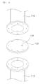
FIG. 4 is an exploded perspective showing the portion "A" ofFIG. 3 . -
FIG. 5 is a cross-sectional view showing the flow of hydrogen and sea water fed into the electrolyzer for electrolysis apparatus according to the preferred embodiment of the present invention. -
FIG. 6 is a perspective view showing the construction of an electrolyzer for electrolysis apparatus according to another preferred embodiment of the present invention. - It should be understood that the terms used in the specification and the appended claims should not be construed as limited to general and dictionary meanings, but interpreted based on the meanings and concepts corresponding to technical aspects of the present invention on the basis of the principle that the inventor is allowed to define terms appropriately for the best explanation.
- Hereinafter, a description will be given as to an electrolyzer structure for electrolysis apparatus according to a preferred embodiment of the present invention with reference to
FIGS. 3 ,4 and5 . - The electrolysis apparatus is used to electrolyze sea water and generate hypochlorite.
- In the electrolysis apparatus, the electrolyzer which the sea water enters consists of, as shown in
FIG. 3 , a plurality oftransport pipes 100 stacked on top of one another. - Because the
plural transport pipes 100 are arranged in series, the electrolyzer has an inlet opening 100a on the bottom portion on the one side to provide an intake for sea water, and an outlet opening 100b on the top portion on the other side to discharge the electrolyzed sea water. - The flow passage of the
transport pipes 100 is formed in a zigzag pattern, as described later in detail. - Each
transport pipe 100 consists of abranch pipe 110 and amain pipe 120. - The
branch pipe 110 is to change the flow direction of the fluid. A plurality ofbranch pipes 110 are provided on either side of thetransport pipe 100 and stacked on top of one another. - The
branch pipes 110 are T-shaped. Thebranch pipe 110 on the one side of thetransport pipe 100 is placed opposite to thebranch pipe 110 on the other side. - The
main pipe 120 provides a linear flow passage for the fluid and connects the two opposingbranch pipes 110 together. - Inside the
main pipe 120 is placed an electrode (not shown) in the lengthwise direction to electrolyze the sea water. - On the other hand, a cut-
off plate 130 is provided between the twoadjacent branch pipes 110 stacked on top of one the other. The cut-off plate 130 is placed between thebranch pipes 110 alternately from bottom to top. - The cut-
off plate 130 forms the flow passage in a zigzag pattern in the electrolyzer by intentionally cutting off the flow passage between the twoadjacent branch pipes 110 stacked on top of one the other. - The cut-
off plate 130 is placed in the portion "A" ofFIG. 3 . - In other words, with the cut-off plates, the
branch pipes 110 stacked on top of one another on the one side (that is, on the left side of the drawing) provide a flow passage in the closed-open-closed pattern from bottom to top, while thebranch pipes 110 stacked on top of one another on the other side provide a flow passage in the open-closed-open pattern from bottom to top. - As shown in
FIG. 4 , the cut-off plate 130 has anorifice hole 131. - The
orifice hole 131 is a passage through which the hydrogen generated from the sea water during the electrolysis process can be exhausted from onebranch pipe 110 directly to the upperadjacent branch pipe 110 without passing the electrode of themain pipe 120. - As the
orifice hole 131 keeps the hydrogen from entering themain pipe 120 having an electrode, it can prevent deterioration in performance of the electrode possibly caused by the contact between the electrode and the hydrogen. - The
uppermost branch pipe 110 has anexhaust pipe 140 through which the hydrogen is lastly let out. - Hereinafter, reference will be made to
FIG. 5 to describe the flow of a fluid in the above-constructed electrolyzer. - The sea water entering the electrolyzer through the
inlet opening 100a on the one side (that is, the left side of the drawing) passes themain pipe 120 and undergoes electrolysis via the electrode mounted in themain pipe 120. - The electrolysis of the sea water forms hypochlorite and hydrogen.
- Then, electrolyte that is the electrolyzed sea water flows from the
branch pipe 110a on the other side (that is, the left side of the drawing) up to the upperadjacent branch pipe 110b. As the cut-off plate 130 closes the upward flow passage from thebranch pipe 110b, the electrolyte is directed to thebranch pipe 110c on the one side. - While the flow is turning from the other side to the one side, the gaseous hydrogen undergoes gas-liquid separation and directly goes out to the upper
adjacent branch pipe 110e through theorifice hole 131 of the cut-off plate 130. - In other words, as can be seen in
FIG. 5 , the hydrogen does not pass through themain pipe 120 together with the electrolyte but directly goes out to theupper branch pipe 110e. - The electrolyte transported from the other side to the one side passes through the
main pipe 120 to undergo a second electrolysis via the electrode. - The electrolysis produces hydrogen again. The electrolyte together with the hydrogen after electrolysis flows up to the upper
adjacent branch pipe 110d. As the cut-off plate 130 closes the upward flow passage from thebranch pipe 110d, the electrolyte is directed to thebranch pipe 110e on the other side through themain pipe 120. - In the meantime, the hydrogen does not pass through the
main pipe 120 together with the electrolyte but directly goes out to the upperadjacent branch pipe 110g through theorifice hole 131 of the cut-off plate 130. The hydrogen is then discharged to the gas isolator (not shown) through theexhaust pipe 140 formed on thebranch pipe 110g. - On the other hand, the electrolyte transported from the
branch pipe 110d on the one side to thebranch pipe 110e on the other side through themain pipe 120 flows up to theupper branch pipe 110f together with the hydrogen exhausted from the loweradjacent branch pipe 110b. The electrolyte further goes to thebranch pipe 110g on the one side through themain pipe 120 and exits thebranch pipe 110g through theoutlet opening 100b. - In the meanwhile, the hydrogen transported to the
branch pipe 110f does not flow to thebranch pipe 110g on the one side through themain pipe 120 but goes out through theexhaust pipe 140 formed on thebranch pipe 110f. - As described above, the electrolyzer consisting of a plurality of
transport pipes 100 stacked in series on top of one another is constructed to direct the fluid from bottom to top in a zigzag manner. - Accordingly, the electrolyzer has such a technical characteristic to discharge the fluid at a constant speed of flow without generating scales on the pipes or electrodes.
- Further, the cut-off plates are provided on the close portion of the
branch pipes 110 on either side alternately to change the flow of the fluid in a zigzag pattern. In this regard, the cut-offplates 130 are arranged in a staggered manner on thebranch pipes 110 provided on either side, each cut-off plate 130 having theorifice hole 131. - With such a construction, the hydrogen generated in the electrolysis process does not flow together with the fluid in a zigzag fashion along the
main pipe 120 but directly goes out through theorifice hole 131 without passing through the main pipe 121. - Therefore, the electrode mounted in the
main pipe 120 has a least contact with the hydrogen, minimizing the formation of a hydrogen layer on the electrode and thus preventing deterioration in the performance of the electrode or an increase of the energy consumption caused by a rise of voltage. - Even though the preferred embodiment of the present invention exemplifies the transport pipes stacked in series on top of one another, the transport pipes may also be arranged on front and rear sides and stacked on top of one another.
- This arrangement of the transport pipes can be described according to another embodiment of the present invention with reference to
FIG. 6 . - In the specification, the same reference numbers may be used to denote similar components in various embodiments of the present invention without further explanation.
- As shown in
FIG. 6 ,transport pipes 100 are stacked on top of one another and arranged on front and rear sides. - Each
transport pipe 100 consists of a branch pipe 150 and amain pipe 120. - The
branch pipe 110 provides a flow passage for changing the direction of the flow. A plurality ofbranch pipes 110 are provided on either side of thetransport pipe 100. - Unlike the case of the preferred embodiment, the
branch pipes 110 form a three-way flow passage. - In contrast to the two-way flow passage (i.e., left-and-right direction and up-and-down direction) of the
transport pipes 100 in the preferred embodiment, there is formed a three-way flow passage: left-and-right direction, up-and-down direction, and front-and-rear direction. - As a result, the
transport pipes 100 may be arranged in left-and-right direction, up-and-down direction, and front-and-rear direction. - The
main pipe 120 connects two opposing branch pipes 150 on either side together. Inside themain pipe 120 is placed an electrode. - Such an electrolyzer structure also has a serial component arrangement to form a one-way flow passage.
- In other words,
inlet opening 100a andoutlet opening 100b are formed in the bottom and top portions on the one side, respectively. Between the branch pipes 150 is provided a cut-off plate 130 in order to form a one-way flow passage from inlet opening 100a tooutlet opening 100b. - As the
inlet opening 100a is formed in the bottom portion, the fluid flows in the bottom-to-top direction of the electrolyzer. - The cut-
off plate 130 is provided to keep the fluid from moving to the top portion of the electrolyzer while the fluid is flowing through the branch pipes 150 and themain pipe 120 arranged in the bottom portion. For better understanding, the cut-off plate 130 is shown in the portion "B" only. - The cut-
off plate 130 has anorifice hole 131, which goes all the way to the upper adjacent branch pipe 150. - The uppermost branch pipe 150 has an
exhaust pipe 140 for the final hydrogen discharge. - Hereinafter, a description will be given as to the flow in the above-constructed electrolyzer according to another embodiment of the present invention.
- The sea water entering the electrolyzer through the
inlet opening 100a on the one side (that is, the left side of the drawing) moves to themain pipe 120 and undergoes electrolysis through the electrode mounted provided in themain pipe 120. - The electrolysis of the sea water results in production of hypochlorite and hydrogen.
- As the cut-
off plate 130 closes the upward flow passage, the electrolyte that is the electrolyzed sea water is directed to therear branch pipe 150b. - While the flow is turning from front to rear side, the gaseous hydrogen undergoes gas-liquid separation and directly passes out to the upper
adjacent branch pipe 150f through theorifice hole 131 of the cut-off plate 130. - Subsequently, the hydrogen is discharged through the
exhaust pipe 140. - On the other hand, the electrolyte transported to the
rear branch pipe 150b enters the branch pipe 150c on the one side through themain pipe 120. In the meanwhile, electrolysis takes place again to generate hydrogen. - The electrolyte together with the hydrogen generated from the electrolysis flows to the
upper branch pipe 150d. The hydrogen exits thebranch pipe 150d through theexhaust pipe 140, while the electrolyte flows into thebranch pipe 150e on the other side through themain pipe 120. - The electrolyte transported to the other side flows into the
front branch pipe 150f, turns to thebranch pipe 150g on the one side and then exits thebranch pipe 150g through theoutlet opening 100b. - With this construction according to another embodiment of the present invention, the hydrogen generated in the electrolysis process together with the fluid does not pass through the
main pipe 120 but directly flows upward through theorifice hole 131. - Therefore, the electrode mounted in the
main pipe 120 has a least contact with the hydrogen, minimizing the formation of a hydrogen layer on the electrode and thus preventing deterioration in the performance of the electrode or an increase of the energy consumption caused by a rise of voltage. - The above description of the present invention is provided in detail for the purpose of illustration of the embodiments disclosed herein. But various changes and modifications may be made without changing technical conception of the present invention but not intended to limit the scope of the present invention.
- 100: transport pipe
- 100a: inlet opening
- 100b: outlet opening
- 110 ((110a - 110g): branch pipe
- 120: main pipe
- 130: cut-off plate
- 131: orifice hole
- 140: exhaust pipe
- 150 ((150a - 150g): branch pipe
Claims (3)
- An electrolyzer structure for electrolysis apparatus, comprising:an inlet opening and an outlet opening formed on bottom and top portions on the one side thereof, respectively;a plurality of transport pipes stacked in series on top of one another to form a one-way flow passage in a zigzag pattern; andan electrode placed in each transport pipe to cause an electrical reaction of ballast water flowing into the transport pipe,wherein both end portions of the stacked transport pipes are alternately closed down and up,wherein the closed portion has an orifice hole going all the way to the upper adjacent transport pipe.
- The electrolyzer structure for electrolysis apparatus as claimed in claim 1, wherein the transport pipes comprise:a plurality of branch pipes placed on either side of the transport pipe and stacked on top of one another; anda main pipe provided to connect the branch pipes together,wherein a cut-off plate having an orifice hole is disposed between one branch pipe and an upper adjacent branch pipe thereof,the cut-off plate being placed on the branch pipes on either side of the transport pipe in a staggered manner.
- An electrolyzer structure for electrolysis apparatus, comprising:an inlet opening and an outlet opening formed on bottom and top portions on the one side thereof, respectively;a plurality of transport pipes stacked in series on top of one another and arranged on the front and rear sides to form a one-way flow passage; andan electrode placed in each transport pipe to cause an electrical reaction of ballast water flowing into the transport pipe,wherein the transport pipe comprises a branch pipe for providing a three-way flow passage on either side, and a main pipe for connecting two opposing branch pipes together,wherein a cut-off plate is disposed between the stacked branch pipes to form a one-way flow passage from the inlet opening to the outlet opening,the cut-off plate having an orifice hole.
Applications Claiming Priority (2)
| Application Number | Priority Date | Filing Date | Title |
|---|---|---|---|
| KR1020110047007A KR101679325B1 (en) | 2011-05-18 | 2011-05-18 | Electrolyzer structure of electrolysis apparatus |
| PCT/KR2012/002554 WO2012157847A2 (en) | 2011-05-18 | 2012-04-05 | Electrolyzer structure of electrolysis device |
Publications (3)
| Publication Number | Publication Date |
|---|---|
| EP2711341A2 true EP2711341A2 (en) | 2014-03-26 |
| EP2711341A4 EP2711341A4 (en) | 2015-03-11 |
| EP2711341B1 EP2711341B1 (en) | 2019-06-19 |
Family
ID=47177416
Family Applications (1)
| Application Number | Title | Priority Date | Filing Date |
|---|---|---|---|
| EP12785227.5A Active EP2711341B1 (en) | 2011-05-18 | 2012-04-05 | Electrolyzer structure of electrolysis device |
Country Status (5)
| Country | Link |
|---|---|
| EP (1) | EP2711341B1 (en) |
| JP (1) | JP5832637B2 (en) |
| KR (1) | KR101679325B1 (en) |
| CN (1) | CN103596884B (en) |
| WO (1) | WO2012157847A2 (en) |
Families Citing this family (7)
| Publication number | Priority date | Publication date | Assignee | Title |
|---|---|---|---|---|
| KR101481327B1 (en) * | 2013-10-22 | 2015-01-12 | 현대중공업 주식회사 | Bipolar type electrolysis reactor |
| CN106976955B (en) * | 2017-04-26 | 2020-12-11 | 中国科学院生态环境研究中心 | Electrode, monopolar chamber bioelectrochemical device and method for adjusting its hydraulic flow |
| KR102280040B1 (en) | 2019-11-14 | 2021-07-21 | 현대중공업 주식회사 | Electrolyzer structure of electrolysis apparatus |
| CN110902773A (en) * | 2019-11-15 | 2020-03-24 | 沪东中华造船(集团)有限公司 | Cabin sea water pipe microorganism treatment system and ship |
| KR102451586B1 (en) * | 2020-10-14 | 2022-10-06 | (주)아큐스 | Sodium Hypochlorite generating device |
| CN113856425B (en) * | 2021-11-10 | 2022-06-03 | 南通理工学院 | A electrolytic device for electrolyzing marine water method handles boats and ships tail gas |
| CN116853411B (en) * | 2023-06-29 | 2023-12-08 | 中国船舶集团有限公司第七一九研究所 | Surface microstructure with drag reduction function and forming method thereof |
Family Cites Families (13)
| Publication number | Priority date | Publication date | Assignee | Title |
|---|---|---|---|---|
| US3480529A (en) * | 1965-10-18 | 1969-11-25 | Owen R Waltrip | Electro-chemical method for selected dissociation |
| US3925176A (en) * | 1973-10-10 | 1975-12-09 | Adolph P Okert | Apparatus and method for electrolytic sewage treatment |
| JPS5576085A (en) * | 1978-12-05 | 1980-06-07 | Isomura Housui Kiko Kk | Producing apparatus of sodium hypochlorite |
| JPS5951066U (en) * | 1982-09-28 | 1984-04-04 | 横浜電工株式会社 | Diaphragmless horizontal parallel branch type bipolar electrolyzer |
| KR19980034458U (en) * | 1996-12-10 | 1998-09-15 | 박병재 | silencer |
| JP2002531704A (en) * | 1998-12-07 | 2002-09-24 | ザッピ・ウォーター・ピューリフィケーション・システムズ・インコーポレーテッド | Electrolytic apparatus, method for purifying aqueous solution, and method for synthesizing chemical substance |
| JP2002307070A (en) | 2001-04-17 | 2002-10-22 | Haccpper Giken:Kk | Seawater treatment equipment and treatment method |
| JP4460439B2 (en) * | 2004-01-09 | 2010-05-12 | エア・ウォーター株式会社 | Solution quality control method and apparatus |
| US20060283718A1 (en) * | 2005-06-21 | 2006-12-21 | Schreppel Rudy Jr | Reactor loop for producing hydroxyl water |
| US20080258080A1 (en) * | 2007-04-23 | 2008-10-23 | Bill Rippe Toe | Method and apparatus for treating fluids to alter their physical characteristics |
| CN101781043B (en) * | 2010-02-10 | 2012-09-26 | 青岛海德威科技有限公司 | Novel ballast water treatment method and device |
| CN201770560U (en) * | 2010-08-13 | 2011-03-23 | 宁波四通金属制品有限公司 | Ship sewage treatment device |
| KR101211033B1 (en) * | 2011-03-24 | 2012-12-11 | 한국원자력연구원 | Electrochemical system which consists of oblique cylinder reator |
-
2011
- 2011-05-18 KR KR1020110047007A patent/KR101679325B1/en not_active Expired - Fee Related
-
2012
- 2012-04-05 CN CN201280022422.8A patent/CN103596884B/en not_active Expired - Fee Related
- 2012-04-05 EP EP12785227.5A patent/EP2711341B1/en active Active
- 2012-04-05 WO PCT/KR2012/002554 patent/WO2012157847A2/en not_active Ceased
- 2012-04-05 JP JP2014510239A patent/JP5832637B2/en not_active Expired - Fee Related
Also Published As
| Publication number | Publication date |
|---|---|
| CN103596884B (en) | 2015-04-22 |
| WO2012157847A2 (en) | 2012-11-22 |
| KR101679325B1 (en) | 2016-11-24 |
| KR20120129011A (en) | 2012-11-28 |
| WO2012157847A3 (en) | 2013-02-07 |
| EP2711341A4 (en) | 2015-03-11 |
| CN103596884A (en) | 2014-02-19 |
| JP2014513216A (en) | 2014-05-29 |
| EP2711341B1 (en) | 2019-06-19 |
| JP5832637B2 (en) | 2015-12-16 |
Similar Documents
| Publication | Publication Date | Title |
|---|---|---|
| EP2711341B1 (en) | Electrolyzer structure of electrolysis device | |
| TWI504784B (en) | Seawater electrolysis system and seawater electrolysis method | |
| JP5791377B2 (en) | Seawater electrolysis system and seawater electrolysis method | |
| SE452173B (en) | ELECTROLYSIS DEVICE FOR ELECTROLYSIS OF SALT SOLUTIONS FOR PREPARATION OF HYPOOCLORITE | |
| US6516738B2 (en) | Method and apparatus for delivering ozone to ballast tanks | |
| US20130140171A1 (en) | Electrolyser module | |
| JP2012111990A (en) | Apparatus, system and method for electrolyzing seawater | |
| US5378324A (en) | Process and an electrolytic cell for the production of fluorine | |
| KR20170040680A (en) | electrolytic apparatus | |
| KR20120002074A (en) | High concentration sodium hypochlorite aqueous solution manufacturing device | |
| US7955481B2 (en) | Internal flow control in electrolytic cells | |
| US10287200B2 (en) | Method for treating ballast water and device for treating ballast water used therefor | |
| JP6114335B2 (en) | Seawater electrolysis system and seawater electrolysis method | |
| KR101731659B1 (en) | Electrolyzer of electrolysis apparatus | |
| FI65091C (en) | ELEKTROLYSCELL | |
| CN118026362A (en) | A low-flow electrolysis ballast water treatment system | |
| EP3299342B1 (en) | Dehydrogenation tank for ballast water treatment system having same | |
| KR102280040B1 (en) | Electrolyzer structure of electrolysis apparatus | |
| EP3055255A1 (en) | Apparatus and method for electrochemical treatment of water | |
| CN216890228U (en) | Ballast water cyclone separator | |
| CN206157238U (en) | Electrolyzes seawater method ship ballast water processing system | |
| KR100592331B1 (en) | Electrolyzer for generating sodium hypochlorite | |
| CN202705499U (en) | Electrolytic bath with multilayer vibration screen plate | |
| KR102086912B1 (en) | Ballast water treatment system | |
| JPH08158086A (en) | Salt water electrolytic cell |
Legal Events
| Date | Code | Title | Description |
|---|---|---|---|
| PUAI | Public reference made under article 153(3) epc to a published international application that has entered the european phase |
Free format text: ORIGINAL CODE: 0009012 |
|
| 17P | Request for examination filed |
Effective date: 20131113 |
|
| AK | Designated contracting states |
Kind code of ref document: A2 Designated state(s): AL AT BE BG CH CY CZ DE DK EE ES FI FR GB GR HR HU IE IS IT LI LT LU LV MC MK MT NL NO PL PT RO RS SE SI SK SM TR |
|
| RIN1 | Information on inventor provided before grant (corrected) |
Inventor name: KIM, YANG-GYU Inventor name: LEE, TAE-JIN Inventor name: HAN, KI-HOON Inventor name: JEONG, GIL-JU Inventor name: LEE, JI-HYOUNG |
|
| DAX | Request for extension of the european patent (deleted) | ||
| A4 | Supplementary search report drawn up and despatched |
Effective date: 20150209 |
|
| RIC1 | Information provided on ipc code assigned before grant |
Ipc: C02F 1/461 20060101ALI20150203BHEP Ipc: B63B 13/00 20060101ALI20150203BHEP Ipc: C25B 9/00 20060101ALI20150203BHEP Ipc: C02F 1/467 20060101AFI20150203BHEP |
|
| GRAP | Despatch of communication of intention to grant a patent |
Free format text: ORIGINAL CODE: EPIDOSNIGR1 |
|
| STAA | Information on the status of an ep patent application or granted ep patent |
Free format text: STATUS: GRANT OF PATENT IS INTENDED |
|
| INTG | Intention to grant announced |
Effective date: 20190108 |
|
| GRAS | Grant fee paid |
Free format text: ORIGINAL CODE: EPIDOSNIGR3 |
|
| GRAA | (expected) grant |
Free format text: ORIGINAL CODE: 0009210 |
|
| STAA | Information on the status of an ep patent application or granted ep patent |
Free format text: STATUS: THE PATENT HAS BEEN GRANTED |
|
| AK | Designated contracting states |
Kind code of ref document: B1 Designated state(s): AL AT BE BG CH CY CZ DE DK EE ES FI FR GB GR HR HU IE IS IT LI LT LU LV MC MK MT NL NO PL PT RO RS SE SI SK SM TR |
|
| REG | Reference to a national code |
Ref country code: GB Ref legal event code: FG4D |
|
| REG | Reference to a national code |
Ref country code: CH Ref legal event code: EP |
|
| REG | Reference to a national code |
Ref country code: IE Ref legal event code: FG4D |
|
| REG | Reference to a national code |
Ref country code: DE Ref legal event code: R096 Ref document number: 602012061203 Country of ref document: DE |
|
| REG | Reference to a national code |
Ref country code: AT Ref legal event code: REF Ref document number: 1145280 Country of ref document: AT Kind code of ref document: T Effective date: 20190715 |
|
| REG | Reference to a national code |
Ref country code: NL Ref legal event code: MP Effective date: 20190619 |
|
| PG25 | Lapsed in a contracting state [announced via postgrant information from national office to epo] |
Ref country code: HR Free format text: LAPSE BECAUSE OF FAILURE TO SUBMIT A TRANSLATION OF THE DESCRIPTION OR TO PAY THE FEE WITHIN THE PRESCRIBED TIME-LIMIT Effective date: 20190619 Ref country code: LT Free format text: LAPSE BECAUSE OF FAILURE TO SUBMIT A TRANSLATION OF THE DESCRIPTION OR TO PAY THE FEE WITHIN THE PRESCRIBED TIME-LIMIT Effective date: 20190619 Ref country code: FI Free format text: LAPSE BECAUSE OF FAILURE TO SUBMIT A TRANSLATION OF THE DESCRIPTION OR TO PAY THE FEE WITHIN THE PRESCRIBED TIME-LIMIT Effective date: 20190619 Ref country code: AL Free format text: LAPSE BECAUSE OF FAILURE TO SUBMIT A TRANSLATION OF THE DESCRIPTION OR TO PAY THE FEE WITHIN THE PRESCRIBED TIME-LIMIT Effective date: 20190619 Ref country code: SE Free format text: LAPSE BECAUSE OF FAILURE TO SUBMIT A TRANSLATION OF THE DESCRIPTION OR TO PAY THE FEE WITHIN THE PRESCRIBED TIME-LIMIT Effective date: 20190619 Ref country code: NO Free format text: LAPSE BECAUSE OF FAILURE TO SUBMIT A TRANSLATION OF THE DESCRIPTION OR TO PAY THE FEE WITHIN THE PRESCRIBED TIME-LIMIT Effective date: 20190919 |
|
| REG | Reference to a national code |
Ref country code: LT Ref legal event code: MG4D |
|
| PG25 | Lapsed in a contracting state [announced via postgrant information from national office to epo] |
Ref country code: LV Free format text: LAPSE BECAUSE OF FAILURE TO SUBMIT A TRANSLATION OF THE DESCRIPTION OR TO PAY THE FEE WITHIN THE PRESCRIBED TIME-LIMIT Effective date: 20190619 Ref country code: GR Free format text: LAPSE BECAUSE OF FAILURE TO SUBMIT A TRANSLATION OF THE DESCRIPTION OR TO PAY THE FEE WITHIN THE PRESCRIBED TIME-LIMIT Effective date: 20190920 Ref country code: RS Free format text: LAPSE BECAUSE OF FAILURE TO SUBMIT A TRANSLATION OF THE DESCRIPTION OR TO PAY THE FEE WITHIN THE PRESCRIBED TIME-LIMIT Effective date: 20190619 Ref country code: BG Free format text: LAPSE BECAUSE OF FAILURE TO SUBMIT A TRANSLATION OF THE DESCRIPTION OR TO PAY THE FEE WITHIN THE PRESCRIBED TIME-LIMIT Effective date: 20190919 |
|
| REG | Reference to a national code |
Ref country code: AT Ref legal event code: MK05 Ref document number: 1145280 Country of ref document: AT Kind code of ref document: T Effective date: 20190619 |
|
| PG25 | Lapsed in a contracting state [announced via postgrant information from national office to epo] |
Ref country code: RO Free format text: LAPSE BECAUSE OF FAILURE TO SUBMIT A TRANSLATION OF THE DESCRIPTION OR TO PAY THE FEE WITHIN THE PRESCRIBED TIME-LIMIT Effective date: 20190619 Ref country code: CZ Free format text: LAPSE BECAUSE OF FAILURE TO SUBMIT A TRANSLATION OF THE DESCRIPTION OR TO PAY THE FEE WITHIN THE PRESCRIBED TIME-LIMIT Effective date: 20190619 Ref country code: NL Free format text: LAPSE BECAUSE OF FAILURE TO SUBMIT A TRANSLATION OF THE DESCRIPTION OR TO PAY THE FEE WITHIN THE PRESCRIBED TIME-LIMIT Effective date: 20190619 Ref country code: PT Free format text: LAPSE BECAUSE OF FAILURE TO SUBMIT A TRANSLATION OF THE DESCRIPTION OR TO PAY THE FEE WITHIN THE PRESCRIBED TIME-LIMIT Effective date: 20191021 Ref country code: AT Free format text: LAPSE BECAUSE OF FAILURE TO SUBMIT A TRANSLATION OF THE DESCRIPTION OR TO PAY THE FEE WITHIN THE PRESCRIBED TIME-LIMIT Effective date: 20190619 Ref country code: EE Free format text: LAPSE BECAUSE OF FAILURE TO SUBMIT A TRANSLATION OF THE DESCRIPTION OR TO PAY THE FEE WITHIN THE PRESCRIBED TIME-LIMIT Effective date: 20190619 Ref country code: SK Free format text: LAPSE BECAUSE OF FAILURE TO SUBMIT A TRANSLATION OF THE DESCRIPTION OR TO PAY THE FEE WITHIN THE PRESCRIBED TIME-LIMIT Effective date: 20190619 |
|
| PG25 | Lapsed in a contracting state [announced via postgrant information from national office to epo] |
Ref country code: ES Free format text: LAPSE BECAUSE OF FAILURE TO SUBMIT A TRANSLATION OF THE DESCRIPTION OR TO PAY THE FEE WITHIN THE PRESCRIBED TIME-LIMIT Effective date: 20190619 Ref country code: IT Free format text: LAPSE BECAUSE OF FAILURE TO SUBMIT A TRANSLATION OF THE DESCRIPTION OR TO PAY THE FEE WITHIN THE PRESCRIBED TIME-LIMIT Effective date: 20190619 Ref country code: IS Free format text: LAPSE BECAUSE OF FAILURE TO SUBMIT A TRANSLATION OF THE DESCRIPTION OR TO PAY THE FEE WITHIN THE PRESCRIBED TIME-LIMIT Effective date: 20191019 Ref country code: SM Free format text: LAPSE BECAUSE OF FAILURE TO SUBMIT A TRANSLATION OF THE DESCRIPTION OR TO PAY THE FEE WITHIN THE PRESCRIBED TIME-LIMIT Effective date: 20190619 |
|
| PG25 | Lapsed in a contracting state [announced via postgrant information from national office to epo] |
Ref country code: TR Free format text: LAPSE BECAUSE OF FAILURE TO SUBMIT A TRANSLATION OF THE DESCRIPTION OR TO PAY THE FEE WITHIN THE PRESCRIBED TIME-LIMIT Effective date: 20190619 |
|
| PG25 | Lapsed in a contracting state [announced via postgrant information from national office to epo] |
Ref country code: DK Free format text: LAPSE BECAUSE OF FAILURE TO SUBMIT A TRANSLATION OF THE DESCRIPTION OR TO PAY THE FEE WITHIN THE PRESCRIBED TIME-LIMIT Effective date: 20190619 Ref country code: PL Free format text: LAPSE BECAUSE OF FAILURE TO SUBMIT A TRANSLATION OF THE DESCRIPTION OR TO PAY THE FEE WITHIN THE PRESCRIBED TIME-LIMIT Effective date: 20190619 |
|
| PG25 | Lapsed in a contracting state [announced via postgrant information from national office to epo] |
Ref country code: IS Free format text: LAPSE BECAUSE OF FAILURE TO SUBMIT A TRANSLATION OF THE DESCRIPTION OR TO PAY THE FEE WITHIN THE PRESCRIBED TIME-LIMIT Effective date: 20200224 |
|
| REG | Reference to a national code |
Ref country code: DE Ref legal event code: R097 Ref document number: 602012061203 Country of ref document: DE |
|
| PLBE | No opposition filed within time limit |
Free format text: ORIGINAL CODE: 0009261 |
|
| STAA | Information on the status of an ep patent application or granted ep patent |
Free format text: STATUS: NO OPPOSITION FILED WITHIN TIME LIMIT |
|
| PG2D | Information on lapse in contracting state deleted |
Ref country code: IS |
|
| 26N | No opposition filed |
Effective date: 20200603 |
|
| PG25 | Lapsed in a contracting state [announced via postgrant information from national office to epo] |
Ref country code: SI Free format text: LAPSE BECAUSE OF FAILURE TO SUBMIT A TRANSLATION OF THE DESCRIPTION OR TO PAY THE FEE WITHIN THE PRESCRIBED TIME-LIMIT Effective date: 20190619 |
|
| REG | Reference to a national code |
Ref country code: DE Ref legal event code: R119 Ref document number: 602012061203 Country of ref document: DE |
|
| PG25 | Lapsed in a contracting state [announced via postgrant information from national office to epo] |
Ref country code: MC Free format text: LAPSE BECAUSE OF FAILURE TO SUBMIT A TRANSLATION OF THE DESCRIPTION OR TO PAY THE FEE WITHIN THE PRESCRIBED TIME-LIMIT Effective date: 20190619 |
|
| REG | Reference to a national code |
Ref country code: CH Ref legal event code: PL |
|
| PG25 | Lapsed in a contracting state [announced via postgrant information from national office to epo] |
Ref country code: CH Free format text: LAPSE BECAUSE OF NON-PAYMENT OF DUE FEES Effective date: 20200430 Ref country code: DE Free format text: LAPSE BECAUSE OF NON-PAYMENT OF DUE FEES Effective date: 20201103 Ref country code: LU Free format text: LAPSE BECAUSE OF NON-PAYMENT OF DUE FEES Effective date: 20200405 Ref country code: FR Free format text: LAPSE BECAUSE OF NON-PAYMENT OF DUE FEES Effective date: 20200430 Ref country code: LI Free format text: LAPSE BECAUSE OF NON-PAYMENT OF DUE FEES Effective date: 20200430 |
|
| REG | Reference to a national code |
Ref country code: BE Ref legal event code: MM Effective date: 20200430 |
|
| PG25 | Lapsed in a contracting state [announced via postgrant information from national office to epo] |
Ref country code: BE Free format text: LAPSE BECAUSE OF NON-PAYMENT OF DUE FEES Effective date: 20200430 |
|
| GBPC | Gb: european patent ceased through non-payment of renewal fee |
Effective date: 20200405 |
|
| PG25 | Lapsed in a contracting state [announced via postgrant information from national office to epo] |
Ref country code: GB Free format text: LAPSE BECAUSE OF NON-PAYMENT OF DUE FEES Effective date: 20200405 Ref country code: IE Free format text: LAPSE BECAUSE OF NON-PAYMENT OF DUE FEES Effective date: 20200405 |
|
| PG25 | Lapsed in a contracting state [announced via postgrant information from national office to epo] |
Ref country code: MT Free format text: LAPSE BECAUSE OF FAILURE TO SUBMIT A TRANSLATION OF THE DESCRIPTION OR TO PAY THE FEE WITHIN THE PRESCRIBED TIME-LIMIT Effective date: 20190619 Ref country code: CY Free format text: LAPSE BECAUSE OF FAILURE TO SUBMIT A TRANSLATION OF THE DESCRIPTION OR TO PAY THE FEE WITHIN THE PRESCRIBED TIME-LIMIT Effective date: 20190619 |
|
| PG25 | Lapsed in a contracting state [announced via postgrant information from national office to epo] |
Ref country code: MK Free format text: LAPSE BECAUSE OF FAILURE TO SUBMIT A TRANSLATION OF THE DESCRIPTION OR TO PAY THE FEE WITHIN THE PRESCRIBED TIME-LIMIT Effective date: 20190619 |