EP2711184A1 - Printing device - Google Patents
Printing device Download PDFInfo
- Publication number
- EP2711184A1 EP2711184A1 EP11865727.9A EP11865727A EP2711184A1 EP 2711184 A1 EP2711184 A1 EP 2711184A1 EP 11865727 A EP11865727 A EP 11865727A EP 2711184 A1 EP2711184 A1 EP 2711184A1
- Authority
- EP
- European Patent Office
- Prior art keywords
- mask
- printing
- raising
- mechanical part
- screen mask
- Prior art date
- Legal status (The legal status is an assumption and is not a legal conclusion. Google has not performed a legal analysis and makes no representation as to the accuracy of the status listed.)
- Granted
Links
Images



Classifications
-
- B—PERFORMING OPERATIONS; TRANSPORTING
- B41—PRINTING; LINING MACHINES; TYPEWRITERS; STAMPS
- B41F—PRINTING MACHINES OR PRESSES
- B41F15/00—Screen printers
- B41F15/14—Details
- B41F15/34—Screens, Frames; Holders therefor
-
- B—PERFORMING OPERATIONS; TRANSPORTING
- B41—PRINTING; LINING MACHINES; TYPEWRITERS; STAMPS
- B41F—PRINTING MACHINES OR PRESSES
- B41F15/00—Screen printers
- B41F15/08—Machines
- B41F15/0881—Machines for printing on polyhedral articles
-
- B—PERFORMING OPERATIONS; TRANSPORTING
- B41—PRINTING; LINING MACHINES; TYPEWRITERS; STAMPS
- B41F—PRINTING MACHINES OR PRESSES
- B41F15/00—Screen printers
- B41F15/14—Details
- B41F15/34—Screens, Frames; Holders therefor
- B41F15/36—Screens, Frames; Holders therefor flat
-
- B—PERFORMING OPERATIONS; TRANSPORTING
- B41—PRINTING; LINING MACHINES; TYPEWRITERS; STAMPS
- B41F—PRINTING MACHINES OR PRESSES
- B41F15/00—Screen printers
- B41F15/14—Details
- B41F15/40—Inking units
- B41F15/42—Inking units comprising squeegees or doctors
- B41F15/423—Driving means for reciprocating squeegees
-
- H—ELECTRICITY
- H05—ELECTRIC TECHNIQUES NOT OTHERWISE PROVIDED FOR
- H05K—PRINTED CIRCUITS; CASINGS OR CONSTRUCTIONAL DETAILS OF ELECTRIC APPARATUS; MANUFACTURE OF ASSEMBLAGES OF ELECTRICAL COMPONENTS
- H05K3/00—Apparatus or processes for manufacturing printed circuits
- H05K3/10—Apparatus or processes for manufacturing printed circuits in which conductive material is applied to the insulating support in such a manner as to form the desired conductive pattern
- H05K3/12—Apparatus or processes for manufacturing printed circuits in which conductive material is applied to the insulating support in such a manner as to form the desired conductive pattern using thick film techniques, e.g. printing techniques to apply the conductive material or similar techniques for applying conductive paste or ink patterns
- H05K3/1216—Apparatus or processes for manufacturing printed circuits in which conductive material is applied to the insulating support in such a manner as to form the desired conductive pattern using thick film techniques, e.g. printing techniques to apply the conductive material or similar techniques for applying conductive paste or ink patterns by screen printing or stencil printing
-
- B—PERFORMING OPERATIONS; TRANSPORTING
- B41—PRINTING; LINING MACHINES; TYPEWRITERS; STAMPS
- B41P—INDEXING SCHEME RELATING TO PRINTING, LINING MACHINES, TYPEWRITERS, AND TO STAMPS
- B41P2215/00—Screen printing machines
- B41P2215/10—Screen printing machines characterised by their constructional features
- B41P2215/11—Registering devices
- B41P2215/112—Registering devices with means for displacing the frame
-
- H—ELECTRICITY
- H05—ELECTRIC TECHNIQUES NOT OTHERWISE PROVIDED FOR
- H05K—PRINTED CIRCUITS; CASINGS OR CONSTRUCTIONAL DETAILS OF ELECTRIC APPARATUS; MANUFACTURE OF ASSEMBLAGES OF ELECTRICAL COMPONENTS
- H05K3/00—Apparatus or processes for manufacturing printed circuits
- H05K3/30—Assembling printed circuits with electric components, e.g. with resistors
- H05K3/32—Assembling printed circuits with electric components, e.g. with resistors electrically connecting electric components or wires to printed circuits
- H05K3/34—Assembling printed circuits with electric components, e.g. with resistors electrically connecting electric components or wires to printed circuits by soldering
- H05K3/3465—Application of solder
- H05K3/3485—Application of solder paste, slurry or powder
Definitions
- the present invention relates to a printing device including a mask raising/lowering mechanical part for raising and lowering a screen mask, and a print head unit for squeegeeing a screen mask.
- a printing device including a printing device having a mask raising/lowering mechanical part for raising and lowering a screen mask, and a print head unit for squeegeeing a screen mask (for instance, refer to Patent Document 1).
- Patent Document 1 discloses a screen printing machine for printing a solder paste, via a mask, on a work (object to be printed) fixed on a table.
- This screen printing machine is provided with a mask raising/lowering mechanical part for raising and lowering the held mask and positioning the mask in the height direction of the work relative to the table disposed at a predetermined height position.
- a squeegee unit for applying a paste material supplied on a top face of the mask is mounted movably along the top face of the mask.
- the squeegee unit is heavy since it includes a squeegee for wiping the paste material, a printing pressure load mechanical part for pressing the squeegee against the top face of the mask, and a movable mechanical part for performing squeegeeing by moving the squeegee and the printing pressure load mechanical part in the front and back direction.
- Patent Document 1 Japanese Patent Application Publication No. 2010-280068
- An object of the present invention is to provide a printing device capable of inhibiting the height position accuracy of the mask raising/lowering mechanical part from being affected by the movement of the print head unit.
- the printing device for achieving the foregoing object includes a mask raising/lowering mechanical part for raising/lowering, in a state of holding a screen mask, the screen mask in a vertical direction and positioning the screen mask relative to a substrate, a frame part disposed in a state of being independent from a raising/lowering operation of the screen mask, and a print head unit provided movably to the frame part and performing squeegeeing of the screen mask to which a solder has been supplied.
- the printing device 100 is a printing machine for mask-printing a solder paste on a top face 5a of a printed board (wiring substrate) 5 which is loaded into the device body.
- the printed board 5 is an example of the "substrate" of the present invention.
- the printing device 100 is installed on a floor face 1 (refer to Fig. 1 ) to become an X-Y plane.
- the printing device 100 includes one printing unit 90 (outer shape is indicated with a two-dot chain line) on a base 10.
- the printing unit 90 is disposed such that the longitudinal direction, which becomes the loading/unloading direction of the printed board 5, substantially coincides with the X direction of the base 10.
- the loading direction of the printed board 5 in the printing unit 90 is the X direction
- the printing direction of the solder 2 (refer to Fig. 5 ) to the printed board 5 is the Y direction.
- the X direction and the Y direction are directions that are mutually orthogonal on the base 10.
- the right side (X2 side) of Fig. 2 is the loading side of the printed board 5, and the left side (X1 side) of Fig. 2 is the unloading side of the printed board 5.
- the area on the base 10 on the side that is more rightward than the frame structure 40 (top panel part 42) described later disposed on the right side of Fig. 2 is the standby area of the printed board 5 before printing.
- the area on the side that is more leftward than the frame structure 40 (top panel part 42) disposed on the left side of Fig. 2 is the unloading area of the printed board 5 after printing.
- the area sandwiched between the left and right top panel parts 42 corresponds to the printing area of the printed board 5.
- the printing unit 90 When the printing unit 90 is viewed along the X direction in a state where the plurality of outer covers 101 (refer to Fig. 1 ) covering the printing device 100 are removed, as shown in Fig. 4 , the printing unit 90 includes a substrate transport part 20 which is disposed on the base 10 and transports the printed board 5, a horizontal positioning mechanical part 30 which is disposed movably on the base 10 and on which the mask raising/lowering mechanical part 50 described later is mounted, a frame structure 40 mounted on the horizontal positioning mechanical part 30, and a printing mechanical part 60 provided above (Z1 direction) of the mask raising/lowering mechanical part 50. Moreover, as shown in Fig. 3 , the printing device 100 has a built-in control device 80 described later for performing the operational control of the respective parts explained below. Note that the frame structure 40 is an example of the "frame part" of the present invention.
- the substrate transport part 20 has a function of transporting the printed board 5 before printing, which is disposed on the substrate loading side of the printing unit 90, to the printing area with a conveyer belt 21 which moves in the X1 direction, and a function of transporting the printed board 5 after printing from the printing area to the unloading area.
- the printing area refers to an area on the top face 5a of the printed board 5 where the screen mask 6 (refer to Fig. 4 ) is mounted during printing.
- the horizontal positioning mechanical part 30 includes a plurality of sliding mechanical parts 31, and a table 32 fixed to the upper side of the sliding mechanical part 31.
- the plurality of sliding mechanical parts 31 are disposed with a predetermined clearance in the Y direction across the area where the substrate transport part 20 is mounted on the base 10.
- the table 32 is supported by a pair of sliding mechanical parts 31 facing each other in the Y direction.
- the horizontal positioning mechanical part 30 is provided with a drive mechanism not shown for driving the sliding mechanical part 31, and configured to enable the table 32 to move in the X-Y plane based on the foregoing drive mechanism. Note that, by individually driving the respective sliding mechanical parts 31, not only can the table 32 be moved parallel in the Y direction, the table 32 can also be slightly turned around the Z axis in the X-Y plane.
- a frame structure 40 is mounted on a top face 32a of the table 32.
- the frame structure 40 includes a pair of leg parts 41 extending upward (normal direction of the sheet) from the vicinity of corners (four locations) of the table 32, and a top panel part 42 which connects the upper ends of the pair of leg parts 41 in a horizontal direction in the X-Y plane.
- the leg parts 41 are fixed to the top face 32a of the table 32 (refer to Fig. 4 ) with fastening members not shown. Consequently, the top panel part 42 covers the upper side of the substrate transport part 20 via the leg parts 41.
- Fig. 4 the top panel part 42 covers the upper side of the substrate transport part 20 via the leg parts 41.
- the frame structure 40 when the printing unit 90 is viewed from the side along the X direction, the frame structure 40 is formed in a gate-shaped structure by the leg parts 41 and the top panel part 42.
- the top panel part 42 is an example of the "support part" of the present invention. Note that, in Fig. 2 , the illustration of the printing mechanical part 60 (refer to Fig. 4 ) described later provided on a top face 42a of the top panel part 42 is omitted.
- the mask raising/lowering mechanical part 50 is disposed inside the frame structure 40 having the gate-shaped structure.
- the mask raising/lowering mechanical part 50 includes a mask holding table 51 for holding the screen mask 6, four ball screw axes 52 extending downward (Z2 direction) from the mask holding table 51, pulleys 53 which is threadably mounted respectively on the four ball screw axes 52 and mounted rotatably without changing the position of the table 32 in the height direction on the top face 32a, a belt 54 provided for simultaneously rotating the four pulleys 53 in the same direction, and a servo motor 55 which is fixed to the leg parts 41 and drives the belt 54.
- the four pulleys 53 are rotated in the same direction pursuant to the rotation of the servo motor 55, and the four ball screw axes 52 which are threadably mounted on the pulleys 53 are simultaneously moved in the axial direction (Z direction). Consequently, the mask holding table 51 is raised/lowered along the vertical direction (Z direction) while maintaining its horizontal state.
- the mask raising/lowering mechanical part 50 lowers the mask holding table 51 in the Z2 direction during printing, and causes the screen mask 6 held by the mask holding table 51 to come into contact with the top face 5a of the printed board 5 loaded to the printing area. After the printing, the mask raising/lowering mechanical part 50 raises the mask holding table 51 in the Z1 direction, and releases the screen mask 6 from the top face 5a of the printed board 5.
- the frame structure 40 including the mask raising/lowering mechanical part 50 is mounted on the horizontal positioning mechanical part 30.
- the screen mask 6 held by the mask holding table 51 can be aligned in detail in the horizontal plane (in the X-Y plane) relative to the printed board 5 loaded to the printing area.
- a printing mechanical part 60 is provided on the top face 42a of the top panel part 42 in the frame structure 40.
- the tope face 42a of the top panel part 42 configures a horizontal plane as with the top face 10a of the base 10.
- the printing mechanical part 60 has a function of performing printing (squeegeeing) of the solder 2 (refer to Fig. 5 ) to the top face 5a of the printed board 5.
- the printing mechanical part 60 includes a printing pressure load unit 61 which slides in the Y direction while pressing the paste solder 2 against the top face 6a (Z1 side) of the screen mask 6, a solder supplying part 62 which is mounted on the printing pressure load unit 61 and supplies the solder 2 to the top face 6a of the screen mask 6, a ball screw axis 63 extending in the Y direction on the top face 42a, a nut member 64 which is threadably mounted on the ball screw axis 63 and fixed to the side of the solder supplying part 62, and a servo motor 65 for driving the ball screw axis 63.
- the vicinity of both ends in the axial direction (Y direction) is rotatably fixed on the top face 42a by a fixing member 66 and a fixing member 67.
- the servo motor 65 is fixed on the top face 42a by the fixing member 66.
- a rail 15 extending in the Y direction is provided on the top face 42a of the top panel part 42.
- the rail 15 has a length that is longer than the length of the screen mask 6, in the Y direction, held by the mask holding table 51.
- the solder supplying part 62 on which the printing pressure load unit 61 is mounted is installed movably on the rail 15. Consequently, as a result of the rotation of the servo motor 65 the printing pressure load unit 61 moves relatively reciprocally along the printing direction (Y direction) relative to the screen mask 6.
- a squeegee 70 which slides on the top face 6a of the screen mask 6 is mounted on the printing pressure load unit 61 via an expandable/contractable rod 71.
- a lower end 70a of the squeegee 70 comes into contact with the screen mask 6 at a predetermined pressing force as a result of the rod 71 extending from the printing pressure load unit 61 being extended downward (Z2 direction).
- Z2 direction a predetermined pressing force as a result of the rod 71 extending from the printing pressure load unit 61 being extended downward
- a pair of squeegees 70 is provided to face each other in the Y direction, and the squeegee 70 which slides over the screen mask 6 is switched according to the printing direction (Y1 direction, Y2 direction).
- the printing pressure load unit 61 moves reciprocally in the printing direction (Y direction) relative to the mask holding table 51, the solder 2 is printed on the printed board 5.
- the printing pressure load unit 61 is an example of the "print head unit” of the present invention
- the squeegee 70 is an example of the "spatula member" of the present invention.
- the mask raising/lowering mechanical part 50 disposed inside the frame structure 40 and the printing mechanical part 60 disposed on the top panel part 42 of the frame structure 40 are structurally isolated and separated.
- the frame structure 40 (top panel part 42) is disposed in a state of being independent from the raising/lowering operation of the mask holding table 51 holding the screen mask 6 (that is, the raising/lowering operation of the screen mask 6), and the printing mechanical part 60 for performing squeegeeing is provided to the frame structure 40 (top panel part 42). Accordingly, even when the printing pressure load unit 61 of the printing mechanical part 60 moves in the printing direction (Y direction) on the top panel part 42, the weight of the printing pressure load unit 61 is not directly applied to the mask holding table 51 via the screen mask 6.
- the top panel part 42 is disposed with a clearance L1 above the top face 51a of the mask holding table 51. Accordingly, even when the mask holding table 51 is raised to the uppermost position based on the raising/lowering operation of the mask raising/lowering mechanical part 50, a state where the top face 51a is separated at a clearance L1 in the Z2 direction relative to the bottom face 42b of the top panel part 42 is maintained.
- the mask raising/lowering mechanical part 50 raises/lowers the screen mask 6 held by the mask holding table 51 in a vertical direction, in a state of being independent from the top panel part 42, and thereby positions the screen mask 6 relative to the printed board 5.
- the printing mechanical part 60 is provided to the top panel part 42 of the frame structure 40.
- the printing pressure load unit 61 is also moved in the same direction as the moving direction of the mask raising/lowering mechanical part 50.
- the printing pressure load unit 61 is also integrally moved in the X-Y plane in synchronization with the alignment of the screen mask 6 with the printed board 5 in the X-Y plane, the positional relation of the squeegee 70 relative to the screen mask 6 will never change.
- the screen mask 6 and the squeegee 70 are disposed so that the lower end 70a of the squeegee 70 extends in the X direction which is substantially orthogonal to one side of the screen mask 6 in the Y direction (printing direction). Accordingly, even when the frame structure 40 and the mask raising/lowering mechanical part 50 are moved in parallel in the X-Y plane or turned about the Z axis by the horizontal positioning mechanical part 30, it is possible to prevent a state where the squeegee 70 slides obliquely relative to the screen mask 6.
- the mask raising/lowering mechanical part 50 is provided with a substrate camera not shown with the imaging lens thereof facing downward (Z2 direction).
- a fiducial mark (alignment mark) not shown appended to the top face 5a of the printed board 5 is detected by the substrate camera when the printed board 5 is transported in the X1 direction by the substrate transport part 20. Consequently, before the printing is started, the printed board 5 and the screen mask 6 transported to the printing area can be aligned accurately in the horizontal plane (in the X-Y plane).
- the screen mask 6 (refer to Fig. 4 ) is configured from a plate-shaped (sheet-shaped) member having a thickness of approximately 20 ⁇ m or more and approximately 150 ⁇ m or less, and has an opening area where a plurality of openings (not shown) are patterned. Since the sheet-shaped screen mask 6 is flexible, the periphery of the screen mask 6 is fixed with the mask holding table 51 made from a highly rigid member.
- the control device 80 is configured from a CPU (arithmetic processing unit) and a substrate circuit part. Specifically, as shown in Fig. 3 , the control device 80 is mainly configured from an arithmetic processing unit 81, a storage unit 82, an external I/O unit 83, an image processing unit 84 and a drive control unit 85. Note that the drive control unit 85 is an example of the "control unit" of the present invention.
- the arithmetic processing unit 81 is configured from a CPU, and governs the overall operation of the printing unit 90. Moreover, the control operation of the servo motor group is performed by the drive control unit 85 based on commands from the arithmetic processing unit 81.
- the drive control unit 85 performs control of separating the squeegee 70 from the printed board 5 in the upward direction in synchronization with the operation of separating the screen mask 6 from the printed board 5 in the upward direction (Z1 direction).
- the drive control unit 85 performs the operation of simultaneously lifting the rod 71 together with the raising of the mask holding table 51.
- the drive control unit 85 lifts the rod 71 upward in a state where the lower end 70a of the squeegee 70 is in contact with the top face 6a of the screen mask 6 by finely controlling the printing pressure with the printing pressure load unit 61. Consequently, when the screen mask 6 is released from the printed board 5, the state where the squeegee 70 is in contact with the screen mask 6 at a predetermined pressing force is maintained. Accordingly, it is possible to inhibit the screen mask 6 from being released from the printed board 5 while flapping in the vertical direction.
- the storage unit 82 includes an operation program storage unit 82a storing control programs and the like that can be executed by the arithmetic processing unit 81, and a control data storage unit 82b storing data and the like which are required upon performing the printing operation.
- the operation program storage unit 82a is configured from a flash ROM (Read Only Memory)
- the control data storage unit 82b is configured from a RAM (Random Access Memory).
- the external I/O unit 83 has the function of controlling the I/O from various buttons such as the operation start button 95 which are used for operational control, and various sensors such as a substrate position sensor, a mask position sensor, and a squeegee position sensor.
- the image processing unit 84 plays the role of processing image data that was captured by the substrate camera and internally generating data which is required for the operation of the printing unit 90.
- the drive control unit 85 controls the various servo motors of the printing unit 90 based on the control signals output from the arithmetic processing unit 81.
- the servo motors to be controlled included are a servo motor for individually driving the sliding mechanical parts 31 of the horizontal positioning mechanical part 30, a servo motor 65 (refer to Fig. 4 ) for raising/lowering the mask holding table 51 in the Z direction, a servo motor 65 (refer to Fig. 4 ) for moving the printing pressure load unit 61 in the Y direction, a servo motor for raising/lowering the rod 71 in the printing pressure load unit 61, and a servo motor of a transport axis (not shown) provided to the substrate transport part 20.
- the drive control unit 85 can recognize the position in the X-Y plane of the frame structure 40 (mask holding table 51), and the height position (Z direction) and the rotating position (about the Z axis) of the mask holding table 51 based on the signals from an encoder (not shown) of the respective servo motors.
- the control device 80 is connected to an emergency shut-down circuit part 92 provided to the device body.
- Electrically connected to the emergency shut-down circuit part 92 are a cover open switch 93 provided at a predetermined position in the device body, and a push button-type emergency shut-down button 94.
- the cover open switch 93 With the cover open switch 93, the opening and closing of the switch is switched according to the open/closed state of the access cover 101a (refer to Fig. 1 ). Consequently, in a state where the access cover 101a is open, the emergency shut-down circuit part 92 functions and the operation of the printing unit 90 is not started (resumed).
- the emergency shut-down button 94 the emergency shut-down circuit part 92 functions and the operation o is instantaneously discontinued.
- a display panel 102 is provided outside the printing device 100.
- the user can comprehend the progress of the printing operation via the respective display panels 102 and perform mechanical operations according to the contents displayed on the display panel 102.
- the printing device 100 is provided with an indicator light 103.
- the indicator light 103 is disposed at a position that is higher than the upper surface part of the printing device 100, and the user can visually recognize the operation condition of the printing device 100 even from a location away from the printing device 100.
- the substrate camera (not shown) disposed on the mask raising/lowering mechanical part 50 detects a fiducial mark (not shown) appended to the top face 5a of the printed board 5. Subsequently, based on the fiducial mark of the printed board 5 detected by the substrate camera, the sliding mechanical part 31 of the horizontal positioning mechanical part 30 is driven and the printed board 5 and the mask holding table 51 are aligned in the X-Y plane. Consequently, the screen mask 6 is accurately overlapped at a predetermined position on the printed board 5.
- the screen mask 6 held by the mask holding table 51 is lowered in the Z2 direction as a result of the servo motor 55 of the mask raising/lowering mechanical part 50 being driven. Consequently, the screen mask 6 is pressed against the top face 5a of the printed board 5 at a predetermined pressing force.
- the printing pressure load unit 61 is moved to a position near the ends of the printing area on the Y1 side as a result of the servo motor 65 of the printing mechanical part 60 being driven. Subsequently, a predetermined amount of solder 2 is supplied by the solder supplying part 62 to the top face 6a of the screen mask 6. Thereafter, as a result of the rod 71 on the Y1 side of the printing pressure load unit 61 being extended downward, the lower end 70a of the squeegee 70 on the Y1 side comes into contact with the top face 6a of the screen mask 6 at a predetermined pressing force.
- the squeegee 70 is moved in the Y2 direction together with the printing pressure load unit 61, and squeegeeing (wiping operation of the paste solder 2) is performed.
- the solder 2 is printed, via the screen mask 6, on the top face 5a of the printed board 5.
- the screen mask 6 held by the mask holding table 51 is raised in the Z1 direction and released from the printed board 5 as a result of the servo motor 55 being driven.
- the drive control unit 85 (refer to Fig. 3 ) performs the operation of lifting the squeegee 70 upward in synchronization with the operation of releasing the screen mask 6 from the printed board 5.
- the speed of releasing the screen mask 6 speed of raising the mask holding table 51
- the speed of raising the rod 71 speed of raising the squeegee 70
- the screen mask 6 and the squeegee 70 are both raised.
- the rod 71 is lifted upward while causing the lower end 70a of the squeegee 70 to come into contact with the top face 6a of the screen mask 6.
- the load upon raising the squeegee 70 (pressing force of the squeegee 70 against the screen mask 6) is controlled to be smaller than the printing pressure load upon performing squeegeeing. Subsequently, as shown in Fig. 8 , the squeegee 70 is additionally lifted from the position where the raising of the mask holding table 51 has been stopped with a clearance L1 relative to the bottom face 42b of the top panel part 42.
- the conveyer belt 21 of the substrate transport part 20 is driven and the printed board 5, in which the printing is complete, is transported from the printing area to the unloading area in the X1 direction.
- the printing unit 90 printing to the printed board 5 is continuously performed by repeating the foregoing printing operation.
- the squeegee 70 on the Y1 side and the squeegee 70 on the Y2 side are alternately switched in accordance with the printing direction, and the printing pressure load unit 61 is moved reciprocally to perform printing on the printed board 5.
- the printing device 100 includes a frame structure 40 disposed in a state of being independent from the raising/lowering operation (Z direction) of the screen mask 6, and a printing mechanical part 60 including a printing pressure load unit 61 which is provided movably to the frame structure 40 in the Y direction and squeegees the screen mask 6 to which a solder 2 was supplied.
- the frame structure 40 includes a top panel part 42 which extends in a horizontal direction with a clearance above (Z1 direction) the mask raising/lowering mechanical part 50, and the printing mechanical part 60 including the printing pressure load unit 61 is supported movably in a horizontal direction by the top panel part 42. Consequently, when squeegeeing is performed, the printing pressure load unit 61 can be easily moved in the printing direction (Y direction) with the top panel part 42 provided independently above the mask holding table 51.
- the mask raising/lowering mechanical part 50 is configured to raise/lower the screen mask 6 in the vertical direction and position the screen mask 6 relative to the printed board 5 in a state of being independent from the top panel part 42 of the frame structure 40. Consequently, even when the printing pressure load unit 61 moves the top panel part 42 in a horizontal direction pursuant to squeegeeing, since the top panel part 42 and the mask raising/lowering mechanical part 50 (mask holding table 51) are structurally independent from each other, it is possible to easily inhibit the load during the movement of the printing pressure load unit 61 from being directly applied to the mask holding table 51.
- the frame structure 40 further includes a leg part 41 which supports the top panel part 42 from below and extends in a vertical direction, and is formed in a gate-shaped structure by the leg part 41 and the top panel part 42.
- the mask raising/lowering mechanical part 50 is disposed inside the frame structure 40 having the gate-shaped structure. Consequently, the mask raising/lowering mechanical part 50 can be easily disposed inside the frame structure 40 having a gate-shaped structure.
- the printing pressure load unit 61 can be moved in a horizontal direction (printing direction) via the top panel part 42 to become the beam part of the gate-shaped structure having predetermined rigidity. It is thereby possible to inhibit the height position accuracy of the mask raising/lowering mechanical part 50 from being affected by the movement of the printing pressure load unit 61.
- the printing pressure load unit 61 is supported movably in a horizontal direction on a top face 42a side of the top panel part 42 in the frame structure 40. Consequently, space (clearance L1, L2) can be easily secured between the printing pressure load unit 61 and the mask holding table 51, which is below the top panel part 42. Accordingly, the printing pressure load unit 61 and the mask raising/lowering mechanical part 50 can be easily driven respectively in a mutually independent state.
- the printing device 100 further includes a horizontal positioning mechanical part 30 for enabling the mask raising/lowering mechanical part 50 to move on the X-Y plane.
- the leg part 41 of the frame structure 40 is fixed to the horizontal positioning mechanical part 30. Consequently, since the mask raising/lowering mechanical part 50 can be moved in a horizontal direction while stably maintaining the height position accuracy of the mask raising/lowering mechanical part 50, the screen mask 6 can be aligned accurately relative to the printed board 5.
- the printing pressure load unit 61 of the printing mechanical part 60 is configured to move pursuant to the movement of the mask raising/lowering mechanical part 50 in a horizontal direction (Y direction) by the horizontal positioning mechanical part 30. Consequently, in the horizontal direction, the printing pressure load unit 61 and the mask raising/lowering mechanical part 50 can be moved integrally. Accordingly, it is possible to inhibit, as much as possible, a deviation in the relative positional relation (positional relation about the Z axis) of the printing pressure load unit 61 and the mask raising/lowering mechanical part 50 in the horizontal plane (in the X-Y plane).
- the printing pressure load unit 61 (squeegee 70) is inhibited from moving in an oblique direction relative to the appropriate squeegeeing direction (Y direction) of the screen mask 6 during the squeegeeing. Accordingly, the printing quality of the solder 2 to the printed board 5 can be maintained favorably.
- the printing device 100 further includes a drive control unit 85 for controlling the height position of the squeegee 70 during the movement of the screen mask 6 in a vertical direction by the mask raising/lowering mechanical part 50.
- the drive control unit 85 performs control of separating the squeegee 70 from the printed board 5 in synchronization with the operation of separating the screen mask 6 from the printed board 5 in a vertical direction.
- the movement of the squeegee 70 extending from the printing pressure load unit 61 can be appropriately controlled to be in synchronization with the movement of the screen mask 6 in the vertical direction by the mask raising/lowering mechanical part 50. Accordingly, the screen mask 6 can be easily released from the printed board 5 after printing.
- the printing mechanical part 60 is configured to press the screen mask 6, at a predetermined pressing force, with the squeegee 70 when the squeegeeing is performed.
- the drive control unit 85 performs control of separating the squeegee 70 from the printed board 5, in a state where the squeegee 70 is in contact with the screen mask 6, when the screen mask 6 is separated from the printed board 5 by the mask raising/lowering mechanical part 50. Consequently, upon releasing the screen mask 6 from the printed board 5, the screen mask 6 can be released in a state of being in contact with the squeegee 70. Accordingly, it is possible to inhibit the screen mask 6 from being released from the printed board 5 while flapping in the vertical direction. Consequently, it is possible to inhibit the printing quality from deteriorating due to the inappropriate release of the screen mask 6.
- the second embodiment is now explained with reference to Fig. 9 .
- the printing device 200 according to the second embodiment is not provided with a horizontal positioning mechanical part 30 as in the first embodiment, and the frame structure 40 is directly fixed on the base 210.
- the same configuration as the first embodiment in the diagram is illustrated by being given the same reference numeral as in the first embodiment.
- the base 210 is an example of the "seating part" of the present invention.
- the printing device 200 includes a printing unit 290 in which the mask raising/lowering mechanical part 50 is directly fixed to a top face 210a of the base 210. That is, the frame structure 40 provided with the mask raising/lowering mechanical part 50 is configured so that it will not move in the horizontal plane (in the X-Y plane). Accordingly, in the printing device 200, the substrate transport part 220 is configured to be movable in the horizontal plane (in the X-Y plane), and the printed board 5 and the screen mask 6 are thereby aligned in detail.
- the substrate transport part 220 includes a sliding mechanical part 221, and a substrate table 222 fixed to the upper side of the sliding mechanical part 221.
- a plurality of pins (not shown) extending upward from the top face (Z1 side) are mounted on the substrate table 222.
- the printed board 5 is mounted on the substrate table 222 in a state where the bottom face thereof is supported by the pins.
- the substrate transport part 220 is provided with a drive mechanism not shown for driving the sliding mechanical part 221, and the substrate table 222 can move in the X-Y plane based on the foregoing drive mechanism.
- the mask raising/lowering mechanical part 50 disposed in the frame structure 40 and the printing mechanical part 60 disposed on the top panel part 42 of the frame structure 40 are structurally isolated. Accordingly, even when the printing mechanical part 60 moves above the top panel part 42 in the printing direction (Y direction), the weight of the printing mechanical part 60 is not directly applied to the mask holding table 51.
- the remaining configuration of the printing device 200 is the same as the configuration of the printing device 100 in the first embodiment. Moreover, excluding the point that the alignment of the screen mask 6 held by the mask holding table 51 and the printed board 5 is performed on the side of the substrate transport part 220 before the printing is started, the printing operation of the printing device 200 is substantially the same as the printing operation of the printing device 100 in the first embodiment.
- the printing device 200 includes a base 210 on which the mask raising/lowering mechanical part 50 is fixedly mounted, and the leg part 41 of the frame structure 40 is fixed to the base 210.
- the printing device 200 capable of stably maintaining the height position accuracy of the mask raising/lowering mechanical part 50 can be obtained with a simple configuration. Note that the other effects of the second embodiment are the same as those of the first embodiment.
- the third embodiment is now explained with reference to Fig. 3 , Fig. 10 and Fig. 11 .
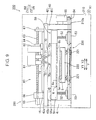
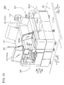
- the printing device 300 according to the third embodiment includes two printing units 290 illustrated in the second embodiment. Note that the same configuration as the second embodiment in the diagram is illustrated by being given the same reference numeral as in the second embodiment.
- the printing device 300 includes two printing units 390 and 391, and, by individually driving the respective printing units, mask-printing is performed to the printed board 5 in the respective printing units.
- the respective printing units can perform printing to printed boards 5 of mutually different sizes.
- the two printing units 390 and 391 are aligned in the Y direction on the base 310 mounted on the floor face 301 (refer to Fig. 10 ).
- the printing units 390 and 391 are disposed such that the longitudinal direction, which becomes the loading/unloading direction of the printed board 5, substantially coincides with the X direction of the base 310.
- the substrate transport part 320 of the printing unit 390 and the substrate transport part 321 of the printing unit 391 can mutually move in the Y direction to a position that is immediately below the mask raising/lowering mechanical part 50 of its counterpart.
- the substrate table 222 of the substrate transport part 320 can move in the Y1 direction while holding the printed board 5 and be aligned with the mask raising/lowering mechanical part 50 of the printing unit 391 in the X-Y plane. Consequently even in cases where the printing mechanical part 60 of the printing unit 390 is unable to perform printing for some reason, printing can be performed by using the mask raising/lowering mechanical part 50 and the printing mechanical part 60 of the printing unit 391. Accordingly, with the printing device 300, the printed board 5 loaded to one printing unit can be transferred to the other printing unit for printing.
- the printing units 390 and 391 respectively include a control device 80 (refer to Fig. 3 ) which is substantially the same as the printing unit 290 illustrated in the second embodiment.
- the respective control devices 80 are connected to an integrated controller (main CPU) not shown.
- the respective printing units are individually driven based on commands from the integrated controller.
- the operations of the respective printing units can also be driven by being mutually associated based on commands from the integrated controller.
- the printed board 5 can be transferred to the printing unit 391 (390) in order to continue the printing process.
- the remaining configuration of the printing units 390 and 391 is substantially the same as the printing unit 290 illustrated in the second embodiment.
- the printing device 300 includes two printing units 390 and 391 having a configuration that is substantially the same as the second embodiment. With this kind of printing device 300 also, it is possible to effectively inhibit the height position accuracy of the mask raising/lowering mechanical part 50 from being affected due to the movement of the printing pressure load unit 61 in the respective printing units. Note that the other effects of the third embodiment are the same as those of the first and second embodiments.
- the present invention is not limited thereto.
- the mask raising/lowering mechanical part 50 may also be mounted on the leg part 41 of the frame structure 40.
- the mask raising/lowering mechanical part 50 can be mounted by providing a support member or the like for supporting the mask holding table 51, in a manner that enables the raising/lowering thereof, to the side face of the leg part 41.
- the printing mechanical part 60 was mounted on the top panel part 42
- the present invention is not limited thereto.
- the printing mechanical part 60 can also be provided movably on the side of the bottom face 42b of the top panel part 42.
- the printing device 400 can be illustrated as shown in a second modified example shown in Fig. 12 .
- the leg part 441 is extending more upward (Z1 direction) in comparison to the frame structure 40 of the first embodiment.
- the printing mechanical part 60 is movably suspended on the bottom face 42b of the top panel part 42 by using the space having a greater clearance L3 (L3 > L2) between the mask holding table 51 and the top panel part 42.
- L3 L3 > L2
- the printing pressure load unit 61 and the mask holding table 51 can be disposed closer to each other in the vertical direction without having to interpose the top panel part 42. Accordingly, the operational control of the printing pressure load unit 61 (raising/lowering operation of the squeegee 70) associated with the raising/lowering operation of the screen mask 6 can be accurately performed while seeking the structural independence of the printing pressure load unit 61 and the mask raising/lowering mechanical part 50.
- the printing pressure load unit 61 and the solder supplying part 62 of the printing mechanical part 60 were driven using the ball screw axis 63 and the nut member 64, which are driven by the servo motor 65
- the present invention is not limited thereto.
- the printing mechanical part 60 (printing pressure load unit 61 and solder supplying part 62) may also be driven by a drive mechanism such as a belt drive, a rack gear, or a pinion gear.
- solder 2 was printed on the printed board 5 based on the contact printing method of performing printing upon causing the printed board 5 and the screen mask 6 to be in close adhesion
- the present invention is not limited thereto.
- the solder 2 can also be printed on the printed board 5 by providing a gap (space) between the printed board 5 and the screen mask 6 and applying the cap printing (off-contact printing) method of simultaneously performing the process of printing (squeegeeing) and plate releasing.
- the present invention is not limited thereto.
- a cartridge head adopting the closed and pressured printing method with an improved filling performance of the solder 2 may also be applied to the "print head unit" of the present invention.
- the printing device includes: a mask raising/lowering mechanical part for raising/lowering, in a state of holding a screen mask, the screen mask in a vertical direction and positioning the screen mask relative to a substrate; a frame part disposed in a state of being independent from the raising/lowering operation of the screen mask; and a print head unit provided movably to the frame part and performing squeegeeing of the screen mask to which a solder has been supplied.
- This printing device includes a frame part disposed in a state of being independent from the raising/lowering operation of the screen mask, and a print head unit which is provided movably to the frame part and squeegees the screen mask to which a solder was supplied. Consequently, even when the print head unit is moved above the screen mask during printing, since the print head unit is provided to a frame part that is structurally independent from the mask raising/lowering mechanical part, it is possible to inhibit the load during the movement of the print head unit from being directly applied to the mask raising/lowering mechanical part. Thus, even when the print head unit is moved, it is possible to inhibit a situation where the mask raising/lowering mechanical part tilts in a vertical direction due to the movement of the print head unit. As a result, it is possible to inhibit the height position accuracy of the mask raising/lowering mechanical part from being affected by the movement of the print head unit.
- the frame part includes a support part extending in a horizontal direction above the mask raising/lowering mechanical part, with a clearance being formed between the support part and the raising/lowering mechanical part, and the print head unit is supported movably in a horizontal direction by the support part.
- the mask raising/lowering mechanical part is configured to raise/lower the screen mask in the vertical direction and position the screen mask relative to the substrate in a state of being independent from the support part of the frame part.
- the frame part includes the support part
- the frame part further includes a leg part extending in a vertical direction, connected to the support part, and supporting the support part from below
- the frame part is formed in a gate-shaped structure by the leg part and the support part
- the mask raising/lowering mechanical part is disposed inside the frame part having the gate-shaped structure.
- the mask raising/lowering mechanical part can be easily disposed inside the frame part having a gate-shaped structure.
- the print head unit can be moved in a horizontal direction (printing direction) via the support part to become the beam part of the gate-shaped structure having predetermined rigidity. It is thereby possible to easily obtain a printing device in which the height position accuracy of the mask raising/lowering mechanical part is inhibited from being affected by the movement of the print head unit.
- the printing device further includes a horizontal positioning mechanical part for enabling the mask raising/lowering mechanical part to move in a horizontal direction, and the leg part of the frame part is fixed to the horizontal positioning mechanical part.
- the print head unit is moved as a result of the movement of the mask raising/lowering mechanical part in a horizontal direction by the horizontal positioning mechanical part.
- the print head unit and the mask raising/lowering mechanical part can be moved integrally. Accordingly, it is possible to inhibit, as much as possible, a deviation in the relative positional relation of the print head unit and the mask raising/lowering mechanical part in the horizontal plane. Since the print head unit is inhibited from moving in an oblique direction relative to the appropriate squeegeeing direction of the screen mask during the squeegeeing, the printing quality of the substrate can be maintained favorably.
- the printing device further includes a seating part on which the mask raising/lowering mechanical part is fixedly mounted, and the leg part of the frame part is fixed to the seating part.
- the print head unit is supported movably in a horizontal direction on a top face side of the support part in the frame part. According to the foregoing configuration, since the print head unit is disposed on the top face side of the support part, space between the print head unit and the mask raising/lowering mechanical part, which is below the support part, can be easily secured. Consequently, the print head unit and the mask raising/lowering mechanical part can be easily driven respectively in a mutually independent state.
- the print head unit is supported movably in a horizontal direction on a bottom face side of the support part in the frame part.
- the print head unit and the mask raising/lowering mechanical part can be disposed closer to each other without having to interpose the support part. Accordingly, the operational control of the print head unit associated with the raising/lowering operation of the mask raising/lowering mechanical part can be accurately performed while seeking the structural independence of the print head unit and the mask raising/lowering mechanical part.
- the print head unit includes a spatula member for performing the squeegeeing, the printing device further including a control unit for controlling a height position of the spatula member during the movement of the screen mask in a vertical direction by the mask raising/lowering mechanical part, wherein the control unit performs control of separating the spatula member from the substrate in synchronization with the operation of separating the screen mask from the substrate in a vertical direction.
- the movement of the spatula member of the print head unit can be appropriately controlled to be in synchronization with the movement of the screen mask in the vertical direction by the mask raising/lowering mechanical part. Accordingly, the screen mask can be easily released from the printed board.
- the print head unit presses the screen mask, at a predetermined pressing force, with the spatula member when the squeegeeing is performed, and the control unit performs control of separating the spatula member from the substrate in a state where the spatula member is in contact with the screen mask when the screen mask is separated from the substrate by the mask raising/lowering mechanical part.
- the screen mask upon releasing the screen mask from the substrate, the screen mask can be released in a state of being in contact with the spatula member. Accordingly, it is possible to inhibit the screen mask from being released from the printed board while flapping in the vertical direction. Consequently, it is possible to inhibit the printing quality from deteriorating due to the inappropriate release of the screen mask.
Landscapes
- Engineering & Computer Science (AREA)
- Mechanical Engineering (AREA)
- Manufacturing & Machinery (AREA)
- Microelectronics & Electronic Packaging (AREA)
- Screen Printers (AREA)
- Electric Connection Of Electric Components To Printed Circuits (AREA)
Abstract
Description
- The present invention relates to a printing device including a mask raising/lowering mechanical part for raising and lowering a screen mask, and a print head unit for squeegeeing a screen mask.
- Conventionally, known is a printing device including a printing device having a mask raising/lowering mechanical part for raising and lowering a screen mask, and a print head unit for squeegeeing a screen mask (for instance, refer to Patent Document 1).
-
Patent Document 1 discloses a screen printing machine for printing a solder paste, via a mask, on a work (object to be printed) fixed on a table. This screen printing machine is provided with a mask raising/lowering mechanical part for raising and lowering the held mask and positioning the mask in the height direction of the work relative to the table disposed at a predetermined height position. Moreover, on the mask raising/lowering mechanical part, a squeegee unit (print head unit) for applying a paste material supplied on a top face of the mask is mounted movably along the top face of the mask. Here, generally speaking, the squeegee unit is heavy since it includes a squeegee for wiping the paste material, a printing pressure load mechanical part for pressing the squeegee against the top face of the mask, and a movable mechanical part for performing squeegeeing by moving the squeegee and the printing pressure load mechanical part in the front and back direction. - Nevertheless, with the screen printing machine described in
Patent Document 1, since the heavy squeegee unit (print head unit) is directly mounted on the mask raising/lowering mechanical part, the squeegee unit itself also moves in the front-back direction within the mask raising/lowering mechanical part together with the movement of the squeegee in the front-back direction. In the foregoing case, the mask raising/lowering mechanical part may tilt in the front-back direction (vertical direction) due to the movement of the squeegee unit. Thus, there is a problem in that the movement of the squeegee unit affects the height position accuracy of the mask raising/lowering mechanical part. - Patent Document 1: Japanese Patent Application Publication No.
2010-280068 - An object of the present invention is to provide a printing device capable of inhibiting the height position accuracy of the mask raising/lowering mechanical part from being affected by the movement of the print head unit.
- The printing device according to one aspect of the present invention for achieving the foregoing object includes a mask raising/lowering mechanical part for raising/lowering, in a state of holding a screen mask, the screen mask in a vertical direction and positioning the screen mask relative to a substrate, a frame part disposed in a state of being independent from a raising/lowering operation of the screen mask, and a print head unit provided movably to the frame part and performing squeegeeing of the screen mask to which a solder has been supplied.
- The object, features and advantages of the present invention will become more apparent based on the ensuing detailed explanation and appended drawings.
-
- [
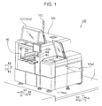
Fig. 1] Fig. 1 is a perspective view showing the overall configuration of the printing device according to the first embodiment of the present invention. - [
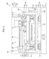
Fig. 2] Fig. 2 is a plan view showing the schematic layout of the printing device according to the first embodiment. - [
Fig. 3] Fig. 3 is a block diagram showing the configuration of the printing unit configuring the printing device according to the first embodiment. - [
Fig. 4] Fig. 4 is a side view upon viewing the printing unit in the printing device according to the first embodiment along the X1 direction. - [
Fig. 5] Fig. 5 is a side view showing the state immediately before starting squeegeeing upon viewing the printing unit in the printing device according to the first embodiment along the X1 direction. - [
Fig. 6] Fig. 6 is a side view showing the state immediately after completing squeegeeing in the foregoing printing device. - [
Fig. 7] Fig. 7 is a side view upon the plate releasing operation in the foregoing printing device. - [
Fig. 8] Fig. 8 is a side view upon housing the squeegee in the foregoing printing device. - [
Fig. 9] Fig. 9 is a side view upon viewing the printing unit in the printing device according to the second embodiment along theX 1 direction. - [
Fig. 10] Fig. 10 is a perspective view showing the overall configuration of the printing device according to the third embodiment of the present invention. - [
Fig. 11] Fig. 11 is a plan view showing the schematic layout of the printing device according to the third embodiment. - [
Fig. 12] Fig. 12 is a side view upon viewing the printing unit in the printing device according to the second modified example of the present invention along the X1 direction. - Embodiments of the present invention are now explained with reference to the drawings.
- The structure of the
printing device 100 according to the first embodiment of the present invention is foremost explained with reference toFig. 1 to Fig. 5 . As shown inFig. 1 , theprinting device 100 is a printing machine for mask-printing a solder paste on atop face 5a of a printed board (wiring substrate) 5 which is loaded into the device body. Note that the printedboard 5 is an example of the "substrate" of the present invention. - The
printing device 100 is installed on a floor face 1 (refer toFig. 1 ) to become an X-Y plane. In a planar view, as shown inFig. 2 , theprinting device 100 includes one printing unit 90 (outer shape is indicated with a two-dot chain line) on abase 10. Theprinting unit 90 is disposed such that the longitudinal direction, which becomes the loading/unloading direction of the printedboard 5, substantially coincides with the X direction of thebase 10. Here, the loading direction of the printedboard 5 in theprinting unit 90 is the X direction, and the printing direction of the solder 2 (refer toFig. 5 ) to the printedboard 5 is the Y direction. Moreover, the X direction and the Y direction are directions that are mutually orthogonal on thebase 10. - In the
printing unit 90, the right side (X2 side) ofFig. 2 is the loading side of the printedboard 5, and the left side (X1 side) ofFig. 2 is the unloading side of the printedboard 5. The area on thebase 10 on the side that is more rightward than the frame structure 40 (top panel part 42) described later disposed on the right side ofFig. 2 is the standby area of the printedboard 5 before printing. Moreover, the area on the side that is more leftward than the frame structure 40 (top panel part 42) disposed on the left side ofFig. 2 is the unloading area of the printedboard 5 after printing. In addition, the area sandwiched between the left and righttop panel parts 42 corresponds to the printing area of the printedboard 5. - When the
printing unit 90 is viewed along the X direction in a state where the plurality of outer covers 101 (refer toFig. 1 ) covering theprinting device 100 are removed, as shown inFig. 4 , theprinting unit 90 includes asubstrate transport part 20 which is disposed on thebase 10 and transports the printedboard 5, a horizontal positioningmechanical part 30 which is disposed movably on thebase 10 and on which the mask raising/loweringmechanical part 50 described later is mounted, aframe structure 40 mounted on the horizontal positioningmechanical part 30, and a printingmechanical part 60 provided above (Z1 direction) of the mask raising/loweringmechanical part 50. Moreover, as shown inFig. 3 , theprinting device 100 has a built-incontrol device 80 described later for performing the operational control of the respective parts explained below. Note that theframe structure 40 is an example of the "frame part" of the present invention. - As shown in
Fig. 2 , thesubstrate transport part 20 has a function of transporting the printedboard 5 before printing, which is disposed on the substrate loading side of theprinting unit 90, to the printing area with aconveyer belt 21 which moves in the X1 direction, and a function of transporting the printedboard 5 after printing from the printing area to the unloading area. Here, the printing area refers to an area on thetop face 5a of the printedboard 5 where the screen mask 6 (refer toFig. 4 ) is mounted during printing. - As shown in
Fig. 4 , the horizontal positioningmechanical part 30 includes a plurality of slidingmechanical parts 31, and a table 32 fixed to the upper side of the slidingmechanical part 31. The plurality of slidingmechanical parts 31 are disposed with a predetermined clearance in the Y direction across the area where thesubstrate transport part 20 is mounted on thebase 10. The table 32 is supported by a pair of slidingmechanical parts 31 facing each other in the Y direction. Moreover, the horizontal positioningmechanical part 30 is provided with a drive mechanism not shown for driving the slidingmechanical part 31, and configured to enable the table 32 to move in the X-Y plane based on the foregoing drive mechanism. Note that, by individually driving the respective slidingmechanical parts 31, not only can the table 32 be moved parallel in the Y direction, the table 32 can also be slightly turned around the Z axis in the X-Y plane. - A
frame structure 40 is mounted on a top face 32a of the table 32. As shown inFig. 2 , theframe structure 40 includes a pair ofleg parts 41 extending upward (normal direction of the sheet) from the vicinity of corners (four locations) of the table 32, and atop panel part 42 which connects the upper ends of the pair ofleg parts 41 in a horizontal direction in the X-Y plane. Here, theleg parts 41 are fixed to the top face 32a of the table 32 (refer toFig. 4 ) with fastening members not shown. Consequently, thetop panel part 42 covers the upper side of thesubstrate transport part 20 via theleg parts 41. Moreover, as shown inFig. 4 , when theprinting unit 90 is viewed from the side along the X direction, theframe structure 40 is formed in a gate-shaped structure by theleg parts 41 and thetop panel part 42. Note that thetop panel part 42 is an example of the "support part" of the present invention. Note that, inFig. 2 , the illustration of the printing mechanical part 60 (refer toFig. 4 ) described later provided on atop face 42a of thetop panel part 42 is omitted. - As shown in
Fig. 4 , the mask raising/loweringmechanical part 50 is disposed inside theframe structure 40 having the gate-shaped structure. Specifically, the mask raising/loweringmechanical part 50 includes a mask holding table 51 for holding thescreen mask 6, fourball screw axes 52 extending downward (Z2 direction) from the mask holding table 51,pulleys 53 which is threadably mounted respectively on the fourball screw axes 52 and mounted rotatably without changing the position of the table 32 in the height direction on the top face 32a, abelt 54 provided for simultaneously rotating the fourpulleys 53 in the same direction, and aservo motor 55 which is fixed to theleg parts 41 and drives thebelt 54. Accordingly, the fourpulleys 53 are rotated in the same direction pursuant to the rotation of theservo motor 55, and the fourball screw axes 52 which are threadably mounted on thepulleys 53 are simultaneously moved in the axial direction (Z direction). Consequently, the mask holding table 51 is raised/lowered along the vertical direction (Z direction) while maintaining its horizontal state. - In the first embodiment, the mask raising/lowering
mechanical part 50 lowers the mask holding table 51 in the Z2 direction during printing, and causes thescreen mask 6 held by the mask holding table 51 to come into contact with thetop face 5a of the printedboard 5 loaded to the printing area. After the printing, the mask raising/loweringmechanical part 50 raises the mask holding table 51 in the Z1 direction, and releases thescreen mask 6 from thetop face 5a of the printedboard 5. - The
frame structure 40 including the mask raising/loweringmechanical part 50 is mounted on the horizontal positioningmechanical part 30. As a result of theframe structure 40 being mounted, thescreen mask 6 held by the mask holding table 51 can be aligned in detail in the horizontal plane (in the X-Y plane) relative to the printedboard 5 loaded to the printing area. - As shown in
Fig. 4 , a printingmechanical part 60 is provided on thetop face 42a of thetop panel part 42 in theframe structure 40. Here, thetope face 42a of thetop panel part 42 configures a horizontal plane as with thetop face 10a of thebase 10. The printingmechanical part 60 has a function of performing printing (squeegeeing) of the solder 2 (refer toFig. 5 ) to thetop face 5a of the printedboard 5. - As shown in
Fig. 5 , the printingmechanical part 60 includes a printingpressure load unit 61 which slides in the Y direction while pressing thepaste solder 2 against thetop face 6a (Z1 side) of thescreen mask 6, asolder supplying part 62 which is mounted on the printingpressure load unit 61 and supplies thesolder 2 to thetop face 6a of thescreen mask 6, aball screw axis 63 extending in the Y direction on thetop face 42a, anut member 64 which is threadably mounted on theball screw axis 63 and fixed to the side of thesolder supplying part 62, and aservo motor 65 for driving theball screw axis 63. Here, with theball screw axis 63, the vicinity of both ends in the axial direction (Y direction) is rotatably fixed on thetop face 42a by a fixingmember 66 and a fixingmember 67. Moreover, theservo motor 65 is fixed on thetop face 42a by the fixingmember 66. - A
rail 15 extending in the Y direction is provided on thetop face 42a of thetop panel part 42. Therail 15 has a length that is longer than the length of thescreen mask 6, in the Y direction, held by the mask holding table 51. In addition, thesolder supplying part 62 on which the printingpressure load unit 61 is mounted is installed movably on therail 15. Consequently, as a result of the rotation of theservo motor 65 the printingpressure load unit 61 moves relatively reciprocally along the printing direction (Y direction) relative to thescreen mask 6. - A
squeegee 70 which slides on thetop face 6a of thescreen mask 6 is mounted on the printingpressure load unit 61 via an expandable/contractable rod 71. With the printingmechanical part 60, when printing is performed, alower end 70a of thesqueegee 70 comes into contact with thescreen mask 6 at a predetermined pressing force as a result of therod 71 extending from the printingpressure load unit 61 being extended downward (Z2 direction). Note that a pair ofsqueegees 70 is provided to face each other in the Y direction, and thesqueegee 70 which slides over thescreen mask 6 is switched according to the printing direction (Y1 direction, Y2 direction). As a result of the printingpressure load unit 61 moving reciprocally in the printing direction (Y direction) relative to the mask holding table 51, thesolder 2 is printed on the printedboard 5. Note that the printingpressure load unit 61 is an example of the "print head unit" of the present invention, and thesqueegee 70 is an example of the "spatula member" of the present invention. - Here, in the first embodiment, as shown in
Fig. 4 andFig. 5 , the mask raising/loweringmechanical part 50 disposed inside theframe structure 40 and the printingmechanical part 60 disposed on thetop panel part 42 of theframe structure 40 are structurally isolated and separated. In other words, the frame structure 40 (top panel part 42) is disposed in a state of being independent from the raising/lowering operation of the mask holding table 51 holding the screen mask 6 (that is, the raising/lowering operation of the screen mask 6), and the printingmechanical part 60 for performing squeegeeing is provided to the frame structure 40 (top panel part 42). Accordingly, even when the printingpressure load unit 61 of the printingmechanical part 60 moves in the printing direction (Y direction) on thetop panel part 42, the weight of the printingpressure load unit 61 is not directly applied to the mask holding table 51 via thescreen mask 6. - Moreover, the
top panel part 42 is disposed with a clearance L1 above thetop face 51a of the mask holding table 51. Accordingly, even when the mask holding table 51 is raised to the uppermost position based on the raising/lowering operation of the mask raising/loweringmechanical part 50, a state where thetop face 51a is separated at a clearance L1 in the Z2 direction relative to thebottom face 42b of thetop panel part 42 is maintained. In addition, the mask raising/loweringmechanical part 50 raises/lowers thescreen mask 6 held by the mask holding table 51 in a vertical direction, in a state of being independent from thetop panel part 42, and thereby positions thescreen mask 6 relative to the printedboard 5. - Moreover, the printing
mechanical part 60 is provided to thetop panel part 42 of theframe structure 40. Thus, when the mask raising/loweringmechanical part 50 is moved in the horizontal direction (in the X-Y plane) by the horizontal positioningmechanical part 30, the printingpressure load unit 61 is also moved in the same direction as the moving direction of the mask raising/loweringmechanical part 50. In other words, since the printingpressure load unit 61 is also integrally moved in the X-Y plane in synchronization with the alignment of thescreen mask 6 with the printedboard 5 in the X-Y plane, the positional relation of thesqueegee 70 relative to thescreen mask 6 will never change. Here, thescreen mask 6 and thesqueegee 70 are disposed so that thelower end 70a of thesqueegee 70 extends in the X direction which is substantially orthogonal to one side of thescreen mask 6 in the Y direction (printing direction). Accordingly, even when theframe structure 40 and the mask raising/loweringmechanical part 50 are moved in parallel in the X-Y plane or turned about the Z axis by the horizontal positioningmechanical part 30, it is possible to prevent a state where thesqueegee 70 slides obliquely relative to thescreen mask 6. - The mask raising/lowering
mechanical part 50 is provided with a substrate camera not shown with the imaging lens thereof facing downward (Z2 direction). With theprinting unit 90, a fiducial mark (alignment mark) not shown appended to thetop face 5a of the printedboard 5 is detected by the substrate camera when the printedboard 5 is transported in the X1 direction by thesubstrate transport part 20. Consequently, before the printing is started, the printedboard 5 and thescreen mask 6 transported to the printing area can be aligned accurately in the horizontal plane (in the X-Y plane). - The screen mask 6 (refer to
Fig. 4 ) is configured from a plate-shaped (sheet-shaped) member having a thickness of approximately 20 µm or more and approximately 150 µm or less, and has an opening area where a plurality of openings (not shown) are patterned. Since the sheet-shapedscreen mask 6 is flexible, the periphery of thescreen mask 6 is fixed with the mask holding table 51 made from a highly rigid member. - The
control device 80 is configured from a CPU (arithmetic processing unit) and a substrate circuit part. Specifically, as shown inFig. 3 , thecontrol device 80 is mainly configured from anarithmetic processing unit 81, astorage unit 82, an external I/O unit 83, animage processing unit 84 and adrive control unit 85. Note that thedrive control unit 85 is an example of the "control unit" of the present invention. - The
arithmetic processing unit 81 is configured from a CPU, and governs the overall operation of theprinting unit 90. Moreover, the control operation of the servo motor group is performed by thedrive control unit 85 based on commands from thearithmetic processing unit 81. - The
drive control unit 85 performs control of separating thesqueegee 70 from the printedboard 5 in the upward direction in synchronization with the operation of separating thescreen mask 6 from the printedboard 5 in the upward direction (Z1 direction). In other words, when thescreen mask 6 is separated upward from the printedboard 5 after the printing to the printedboard 5 is completed from the state (refer toFig. 5 ) in which the mask holding table 51 is lowered with a clearance L2 with thebottom face 42b of thetop panel part 42, thedrive control unit 85 performs the operation of simultaneously lifting therod 71 together with the raising of the mask holding table 51. Here, thedrive control unit 85 lifts therod 71 upward in a state where thelower end 70a of thesqueegee 70 is in contact with thetop face 6a of thescreen mask 6 by finely controlling the printing pressure with the printingpressure load unit 61. Consequently, when thescreen mask 6 is released from the printedboard 5, the state where thesqueegee 70 is in contact with thescreen mask 6 at a predetermined pressing force is maintained. Accordingly, it is possible to inhibit thescreen mask 6 from being released from the printedboard 5 while flapping in the vertical direction. - The
storage unit 82 includes an operationprogram storage unit 82a storing control programs and the like that can be executed by thearithmetic processing unit 81, and a controldata storage unit 82b storing data and the like which are required upon performing the printing operation. Here, the operationprogram storage unit 82a is configured from a flash ROM (Read Only Memory), and the controldata storage unit 82b is configured from a RAM (Random Access Memory). - The external I/
O unit 83 has the function of controlling the I/O from various buttons such as theoperation start button 95 which are used for operational control, and various sensors such as a substrate position sensor, a mask position sensor, and a squeegee position sensor. Theimage processing unit 84 plays the role of processing image data that was captured by the substrate camera and internally generating data which is required for the operation of theprinting unit 90. - The
drive control unit 85 controls the various servo motors of theprinting unit 90 based on the control signals output from thearithmetic processing unit 81. As the servo motors to be controlled, included are a servo motor for individually driving the slidingmechanical parts 31 of the horizontal positioningmechanical part 30, a servo motor 65 (refer toFig. 4 ) for raising/lowering the mask holding table 51 in the Z direction, a servo motor 65 (refer toFig. 4 ) for moving the printingpressure load unit 61 in the Y direction, a servo motor for raising/lowering therod 71 in the printingpressure load unit 61, and a servo motor of a transport axis (not shown) provided to thesubstrate transport part 20. Moreover, thedrive control unit 85 can recognize the position in the X-Y plane of the frame structure 40 (mask holding table 51), and the height position (Z direction) and the rotating position (about the Z axis) of the mask holding table 51 based on the signals from an encoder (not shown) of the respective servo motors. - The
control device 80 is connected to an emergency shut-downcircuit part 92 provided to the device body. Electrically connected to the emergency shut-downcircuit part 92 are a coveropen switch 93 provided at a predetermined position in the device body, and a push button-type emergency shut-downbutton 94. With the coveropen switch 93, the opening and closing of the switch is switched according to the open/closed state of theaccess cover 101a (refer toFig. 1 ). Consequently, in a state where theaccess cover 101a is open, the emergency shut-downcircuit part 92 functions and the operation of theprinting unit 90 is not started (resumed). Moreover, when, during the operation, the user presses the emergency shut-downbutton 94, the emergency shut-downcircuit part 92 functions and the operation o is instantaneously discontinued. - Moreover, as shown in
Fig. 1 , adisplay panel 102 is provided outside theprinting device 100. The user can comprehend the progress of the printing operation via therespective display panels 102 and perform mechanical operations according to the contents displayed on thedisplay panel 102. Moreover, theprinting device 100 is provided with anindicator light 103. Theindicator light 103 is disposed at a position that is higher than the upper surface part of theprinting device 100, and the user can visually recognize the operation condition of theprinting device 100 even from a location away from theprinting device 100. - The printing operation of the
printing device 100 according to the first embodiment of the present invention is now explained with reference toFig. 2 to Fig. 8 . - As shown in
Fig. 2 , let it be assumed that the printedboard 5 before printing has been loaded to the standby position on thesubstrate transport part 20. When the printing operation in theprinting unit 90 is continued, theconveyer belt 21 of thesubstrate transport part 20 is driven and the printedboard 5 is transported to the printing area in the X1 direction. - Referring to
Fig. 4 , subsequently, the substrate camera (not shown) disposed on the mask raising/loweringmechanical part 50 detects a fiducial mark (not shown) appended to thetop face 5a of the printedboard 5. Subsequently, based on the fiducial mark of the printedboard 5 detected by the substrate camera, the slidingmechanical part 31 of the horizontal positioningmechanical part 30 is driven and the printedboard 5 and the mask holding table 51 are aligned in the X-Y plane. Consequently, thescreen mask 6 is accurately overlapped at a predetermined position on the printedboard 5. - In the foregoing state, the
screen mask 6 held by the mask holding table 51 is lowered in the Z2 direction as a result of theservo motor 55 of the mask raising/loweringmechanical part 50 being driven. Consequently, thescreen mask 6 is pressed against thetop face 5a of the printedboard 5 at a predetermined pressing force. - As shown in
Fig. 5 , the printingpressure load unit 61 is moved to a position near the ends of the printing area on the Y1 side as a result of theservo motor 65 of the printingmechanical part 60 being driven. Subsequently, a predetermined amount ofsolder 2 is supplied by thesolder supplying part 62 to thetop face 6a of thescreen mask 6. Thereafter, as a result of therod 71 on the Y1 side of the printingpressure load unit 61 being extended downward, thelower end 70a of thesqueegee 70 on the Y1 side comes into contact with thetop face 6a of thescreen mask 6 at a predetermined pressing force. In the foregoing state, as a result of theservo motor 65 being driven, thesqueegee 70 is moved in the Y2 direction together with the printingpressure load unit 61, and squeegeeing (wiping operation of the paste solder 2) is performed. As a result of thesqueegee 70 being moved to the position shown inFig. 6 , thesolder 2 is printed, via thescreen mask 6, on thetop face 5a of the printedboard 5. After thesolder 2 has been printed, thescreen mask 6 held by the mask holding table 51 is raised in the Z1 direction and released from the printedboard 5 as a result of theservo motor 55 being driven. - Here, as shown in
Fig. 7 , the drive control unit 85 (refer toFig. 3 ) performs the operation of lifting thesqueegee 70 upward in synchronization with the operation of releasing thescreen mask 6 from the printedboard 5. In other words, by causing the speed of releasing the screen mask 6 (speed of raising the mask holding table 51) and the speed of raising the rod 71 (speed of raising the squeegee 70) to be substantially the same, thescreen mask 6 and thesqueegee 70 are both raised. Moreover, here, by controlling the printing pressure load by the printingpressure load unit 61, therod 71 is lifted upward while causing thelower end 70a of thesqueegee 70 to come into contact with thetop face 6a of thescreen mask 6. Note that the load upon raising the squeegee 70 (pressing force of thesqueegee 70 against the screen mask 6) is controlled to be smaller than the printing pressure load upon performing squeegeeing. Subsequently, as shown inFig. 8 , thesqueegee 70 is additionally lifted from the position where the raising of the mask holding table 51 has been stopped with a clearance L1 relative to thebottom face 42b of thetop panel part 42. - Subsequently, as shown in
Fig. 2 , theconveyer belt 21 of thesubstrate transport part 20 is driven and the printedboard 5, in which the printing is complete, is transported from the printing area to the unloading area in the X1 direction. With theprinting unit 90, printing to the printedboard 5 is continuously performed by repeating the foregoing printing operation. - Note that, with regard the printed
board 5 to be printed subsequent to the printedboard 5 explained above, inFig. 8 , by therod 71 on the Y2 side of the printingpressure load unit 61 being extended downward, thesqueegee 70 on the Y2 side comes into contact with thetop face 6a of thescreen mask 6 at a predetermined pressing force. After thesolder 2 is supplied onto thetop face 6a, thesqueegee 70 on the Y2 side is moved in the Y1 direction, and squeegeeing is thereby performed. Subsequently, thesqueegee 70 on the Y1 side and thesqueegee 70 on the Y2 side are alternately switched in accordance with the printing direction, and the printingpressure load unit 61 is moved reciprocally to perform printing on the printedboard 5. - As explained above, according to the first embodiment, the
printing device 100 includes aframe structure 40 disposed in a state of being independent from the raising/lowering operation (Z direction) of thescreen mask 6, and a printingmechanical part 60 including a printingpressure load unit 61 which is provided movably to theframe structure 40 in the Y direction and squeegees thescreen mask 6 to which asolder 2 was supplied. Based on the foregoing configuration, even when the printingpressure load unit 61 of the printingmechanical part 60 is moved in the Y direction (printing direction) above thescreen mask 6 during printing, since the printingmechanical part 60 is provided to theframe structure 40 that is structurally independent from the mask raising/lowering mechanical part 50 (mask holding table 51), it is possible to inhibit the load during the movement of the printingpressure load unit 61 from being directly applied to the mask raising/loweringmechanical part 50. Thus, even when the printingpressure load unit 61 is moved, it is possible to inhibit a situation where the mask holding table 51 tilts in a vertical direction due to the movement of the printingpressure load unit 61. As a result, it is possible to inhibit the height position accuracy of the mask raising/lowering mechanical part 50 (mask holding table 51) from being affected by the movement of the printingpressure load unit 61. - Moreover, the
frame structure 40 includes atop panel part 42 which extends in a horizontal direction with a clearance above (Z1 direction) the mask raising/loweringmechanical part 50, and the printingmechanical part 60 including the printingpressure load unit 61 is supported movably in a horizontal direction by thetop panel part 42. Consequently, when squeegeeing is performed, the printingpressure load unit 61 can be easily moved in the printing direction (Y direction) with thetop panel part 42 provided independently above the mask holding table 51. - The mask raising/lowering
mechanical part 50 is configured to raise/lower thescreen mask 6 in the vertical direction and position thescreen mask 6 relative to the printedboard 5 in a state of being independent from thetop panel part 42 of theframe structure 40. Consequently, even when the printingpressure load unit 61 moves thetop panel part 42 in a horizontal direction pursuant to squeegeeing, since thetop panel part 42 and the mask raising/lowering mechanical part 50 (mask holding table 51) are structurally independent from each other, it is possible to easily inhibit the load during the movement of the printingpressure load unit 61 from being directly applied to the mask holding table 51. - Moreover, the
frame structure 40 further includes aleg part 41 which supports thetop panel part 42 from below and extends in a vertical direction, and is formed in a gate-shaped structure by theleg part 41 and thetop panel part 42. In addition, the mask raising/loweringmechanical part 50 is disposed inside theframe structure 40 having the gate-shaped structure. Consequently, the mask raising/loweringmechanical part 50 can be easily disposed inside theframe structure 40 having a gate-shaped structure. In addition, the printingpressure load unit 61 can be moved in a horizontal direction (printing direction) via thetop panel part 42 to become the beam part of the gate-shaped structure having predetermined rigidity. It is thereby possible to inhibit the height position accuracy of the mask raising/loweringmechanical part 50 from being affected by the movement of the printingpressure load unit 61. - The printing
pressure load unit 61 is supported movably in a horizontal direction on atop face 42a side of thetop panel part 42 in theframe structure 40. Consequently, space (clearance L1, L2) can be easily secured between the printingpressure load unit 61 and the mask holding table 51, which is below thetop panel part 42. Accordingly, the printingpressure load unit 61 and the mask raising/loweringmechanical part 50 can be easily driven respectively in a mutually independent state. - In the first embodiment, the
printing device 100 further includes a horizontal positioningmechanical part 30 for enabling the mask raising/loweringmechanical part 50 to move on the X-Y plane. Theleg part 41 of theframe structure 40 is fixed to the horizontal positioningmechanical part 30. Consequently, since the mask raising/loweringmechanical part 50 can be moved in a horizontal direction while stably maintaining the height position accuracy of the mask raising/loweringmechanical part 50, thescreen mask 6 can be aligned accurately relative to the printedboard 5. - The printing
pressure load unit 61 of the printingmechanical part 60 is configured to move pursuant to the movement of the mask raising/loweringmechanical part 50 in a horizontal direction (Y direction) by the horizontal positioningmechanical part 30. Consequently, in the horizontal direction, the printingpressure load unit 61 and the mask raising/loweringmechanical part 50 can be moved integrally. Accordingly, it is possible to inhibit, as much as possible, a deviation in the relative positional relation (positional relation about the Z axis) of the printingpressure load unit 61 and the mask raising/loweringmechanical part 50 in the horizontal plane (in the X-Y plane). Consequently, the printing pressure load unit 61 (squeegee 70) is inhibited from moving in an oblique direction relative to the appropriate squeegeeing direction (Y direction) of thescreen mask 6 during the squeegeeing. Accordingly, the printing quality of thesolder 2 to the printedboard 5 can be maintained favorably. - Moreover, in the first embodiment, the
printing device 100 further includes adrive control unit 85 for controlling the height position of thesqueegee 70 during the movement of thescreen mask 6 in a vertical direction by the mask raising/loweringmechanical part 50. Thedrive control unit 85 performs control of separating thesqueegee 70 from the printedboard 5 in synchronization with the operation of separating thescreen mask 6 from the printedboard 5 in a vertical direction. Consequently, even in cases where the printingmechanical part 60 is provided to theframe structure 40 which is structurally independent from the mask raising/loweringmechanical part 50, the movement of thesqueegee 70 extending from the printingpressure load unit 61 can be appropriately controlled to be in synchronization with the movement of thescreen mask 6 in the vertical direction by the mask raising/loweringmechanical part 50. Accordingly, thescreen mask 6 can be easily released from the printedboard 5 after printing. - The printing
mechanical part 60 is configured to press thescreen mask 6, at a predetermined pressing force, with thesqueegee 70 when the squeegeeing is performed. Thedrive control unit 85 performs control of separating thesqueegee 70 from the printedboard 5, in a state where thesqueegee 70 is in contact with thescreen mask 6, when thescreen mask 6 is separated from the printedboard 5 by the mask raising/loweringmechanical part 50. Consequently, upon releasing thescreen mask 6 from the printedboard 5, thescreen mask 6 can be released in a state of being in contact with thesqueegee 70. Accordingly, it is possible to inhibit thescreen mask 6 from being released from the printedboard 5 while flapping in the vertical direction. Consequently, it is possible to inhibit the printing quality from deteriorating due to the inappropriate release of thescreen mask 6. - The second embodiment is now explained with reference to
Fig. 9 . Theprinting device 200 according to the second embodiment is not provided with a horizontal positioningmechanical part 30 as in the first embodiment, and theframe structure 40 is directly fixed on thebase 210. Note that the same configuration as the first embodiment in the diagram is illustrated by being given the same reference numeral as in the first embodiment. Note that thebase 210 is an example of the "seating part" of the present invention. - The
printing device 200 includes aprinting unit 290 in which the mask raising/loweringmechanical part 50 is directly fixed to atop face 210a of thebase 210. That is, theframe structure 40 provided with the mask raising/loweringmechanical part 50 is configured so that it will not move in the horizontal plane (in the X-Y plane). Accordingly, in theprinting device 200, thesubstrate transport part 220 is configured to be movable in the horizontal plane (in the X-Y plane), and the printedboard 5 and thescreen mask 6 are thereby aligned in detail. - Specifically, the
substrate transport part 220 includes a slidingmechanical part 221, and a substrate table 222 fixed to the upper side of the slidingmechanical part 221. A plurality of pins (not shown) extending upward from the top face (Z1 side) are mounted on the substrate table 222. The printedboard 5 is mounted on the substrate table 222 in a state where the bottom face thereof is supported by the pins. Moreover, thesubstrate transport part 220 is provided with a drive mechanism not shown for driving the slidingmechanical part 221, and the substrate table 222 can move in the X-Y plane based on the foregoing drive mechanism. - Here, in the second embodiment also, the mask raising/lowering
mechanical part 50 disposed in theframe structure 40 and the printingmechanical part 60 disposed on thetop panel part 42 of theframe structure 40 are structurally isolated. Accordingly, even when the printingmechanical part 60 moves above thetop panel part 42 in the printing direction (Y direction), the weight of the printingmechanical part 60 is not directly applied to the mask holding table 51. - Note that the remaining configuration of the
printing device 200 is the same as the configuration of theprinting device 100 in the first embodiment. Moreover, excluding the point that the alignment of thescreen mask 6 held by the mask holding table 51 and the printedboard 5 is performed on the side of thesubstrate transport part 220 before the printing is started, the printing operation of theprinting device 200 is substantially the same as the printing operation of theprinting device 100 in the first embodiment. - In the second embodiment, as explained above, the
printing device 200 includes a base 210 on which the mask raising/loweringmechanical part 50 is fixedly mounted, and theleg part 41 of theframe structure 40 is fixed to thebase 210. Thus, theprinting device 200 capable of stably maintaining the height position accuracy of the mask raising/loweringmechanical part 50 can be obtained with a simple configuration. Note that the other effects of the second embodiment are the same as those of the first embodiment. - The third embodiment is now explained with reference to
Fig. 3 ,Fig. 10 andFig. 11 . Theprinting device 300 according to the third embodiment includes two printingunits 290 illustrated in the second embodiment. Note that the same configuration as the second embodiment in the diagram is illustrated by being given the same reference numeral as in the second embodiment. - As shown in
Fig. 10 , theprinting device 300 includes two printingunits board 5 in the respective printing units. Here, the respective printing units can perform printing to printedboards 5 of mutually different sizes. - In a planar view, as shown in
Fig. 11 , with theprinting device 300, the twoprinting units Fig. 10 ). Theprinting units board 5, substantially coincides with the X direction of thebase 310. - The
substrate transport part 320 of theprinting unit 390 and thesubstrate transport part 321 of theprinting unit 391 can mutually move in the Y direction to a position that is immediately below the mask raising/loweringmechanical part 50 of its counterpart. For example, the substrate table 222 of thesubstrate transport part 320 can move in the Y1 direction while holding the printedboard 5 and be aligned with the mask raising/loweringmechanical part 50 of theprinting unit 391 in the X-Y plane. Consequently even in cases where the printingmechanical part 60 of theprinting unit 390 is unable to perform printing for some reason, printing can be performed by using the mask raising/loweringmechanical part 50 and the printingmechanical part 60 of theprinting unit 391. Accordingly, with theprinting device 300, the printedboard 5 loaded to one printing unit can be transferred to the other printing unit for printing. - The
printing units Fig. 3 ) which is substantially the same as theprinting unit 290 illustrated in the second embodiment. Therespective control devices 80 are connected to an integrated controller (main CPU) not shown. The respective printing units are individually driven based on commands from the integrated controller. In addition, the operations of the respective printing units can also be driven by being mutually associated based on commands from the integrated controller. In other words, as described above, even in cases when the operation of the printing unit 390 (391) is stopped for some reason, the printedboard 5 can be transferred to the printing unit 391 (390) in order to continue the printing process. Note that the remaining configuration of theprinting units printing unit 290 illustrated in the second embodiment. - As described above, the
printing device 300 includes two printingunits printing device 300 also, it is possible to effectively inhibit the height position accuracy of the mask raising/loweringmechanical part 50 from being affected due to the movement of the printingpressure load unit 61 in the respective printing units. Note that the other effects of the third embodiment are the same as those of the first and second embodiments. - Note that the embodiments disclosed above are merely illustrative in all respective and should not be deemed to be limitative. The scope of the present invention is indicated based on the scope of claims, and not based on the explanation of the foregoing embodiments, and all modifications within the meaning and scope, which are equivalent to the scope of claims, are covered by the present invention.
- For example, in the first to third embodiments, while a case was explained where the mask raising/lowering
mechanical part 50 was mounted on the table 32 of the horizontal positioningmechanical part 30 or thetop face 210a of thebase 210, the present invention is not limited thereto. For example, as a first modified example, the mask raising/loweringmechanical part 50 may also be mounted on theleg part 41 of theframe structure 40. In the foregoing case, the mask raising/loweringmechanical part 50 can be mounted by providing a support member or the like for supporting the mask holding table 51, in a manner that enables the raising/lowering thereof, to the side face of theleg part 41. Even with the configuration of this first modified example, the effects of the present invention can be obtained since thescreen mask 6 can be raised/lowered in the vertical direction in a state where the mask holding table 51 is independent from thetop panel part 42 of theframe structure 40. - Moreover, in the first to third embodiments, while a case was explained where the printing
mechanical part 60 was mounted on thetop panel part 42, the present invention is not limited thereto. For example, the printingmechanical part 60 can also be provided movably on the side of thebottom face 42b of thetop panel part 42. - Specifically, the
printing device 400 can be illustrated as shown in a second modified example shown inFig. 12 . In theprinting unit 490, theleg part 441 is extending more upward (Z1 direction) in comparison to theframe structure 40 of the first embodiment. In addition, the printingmechanical part 60 is movably suspended on thebottom face 42b of thetop panel part 42 by using the space having a greater clearance L3 (L3 > L2) between the mask holding table 51 and thetop panel part 42. Even with the configuration of this second modified example, it is possible to prevent the weight of the printingpressure load unit 61 moving in the Y direction on the side of thebottom face 42b from being directly applied to the mask holding table 51 via thescreen mask 6. In addition, the printingpressure load unit 61 and the mask holding table 51 can be disposed closer to each other in the vertical direction without having to interpose thetop panel part 42. Accordingly, the operational control of the printing pressure load unit 61 (raising/lowering operation of the squeegee 70) associated with the raising/lowering operation of thescreen mask 6 can be accurately performed while seeking the structural independence of the printingpressure load unit 61 and the mask raising/loweringmechanical part 50. - Moreover, in the first to third embodiments, while a case was explained where the printing
pressure load unit 61 and thesolder supplying part 62 of the printingmechanical part 60 were driven using theball screw axis 63 and thenut member 64, which are driven by theservo motor 65, the present invention is not limited thereto. Instead of the ball screw axis and the nut member, for instance, the printing mechanical part 60 (printingpressure load unit 61 and solder supplying part 62) may also be driven by a drive mechanism such as a belt drive, a rack gear, or a pinion gear. - Moreover, in the first to third embodiments, while a case was explained where the
solder 2 was printed on the printedboard 5 based on the contact printing method of performing printing upon causing the printedboard 5 and thescreen mask 6 to be in close adhesion, the present invention is not limited thereto. Thesolder 2 can also be printed on the printedboard 5 by providing a gap (space) between the printedboard 5 and thescreen mask 6 and applying the cap printing (off-contact printing) method of simultaneously performing the process of printing (squeegeeing) and plate releasing. - Moreover, in the first to third embodiments, while a case was explained where printing was performed to the printed
board 5 via the squeezing of thesolder 2 based on the open squeegee method using thesqueegee 70, the present invention is not limited thereto. A cartridge head adopting the closed and pressured printing method with an improved filling performance of thesolder 2 may also be applied to the "print head unit" of the present invention. Even in cases of performing squeegeeing to a screen mask using the cartridge head explained above, since the weight of the print head unit is not directly applied to the mask holding table 51, the height position accuracy of the mask holding table 51 can be appropriately maintained. - Note that the specific embodiments described above mainly include the invention configured as described below.
- The printing device according to one aspect of the present invention includes: a mask raising/lowering mechanical part for raising/lowering, in a state of holding a screen mask, the screen mask in a vertical direction and positioning the screen mask relative to a substrate; a frame part disposed in a state of being independent from the raising/lowering operation of the screen mask; and a print head unit provided movably to the frame part and performing squeegeeing of the screen mask to which a solder has been supplied.
- This printing device includes a frame part disposed in a state of being independent from the raising/lowering operation of the screen mask, and a print head unit which is provided movably to the frame part and squeegees the screen mask to which a solder was supplied. Consequently, even when the print head unit is moved above the screen mask during printing, since the print head unit is provided to a frame part that is structurally independent from the mask raising/lowering mechanical part, it is possible to inhibit the load during the movement of the print head unit from being directly applied to the mask raising/lowering mechanical part. Thus, even when the print head unit is moved, it is possible to inhibit a situation where the mask raising/lowering mechanical part tilts in a vertical direction due to the movement of the print head unit. As a result, it is possible to inhibit the height position accuracy of the mask raising/lowering mechanical part from being affected by the movement of the print head unit.
- In the printing device according to one aspect of the present invention, preferably, the frame part includes a support part extending in a horizontal direction above the mask raising/lowering mechanical part, with a clearance being formed between the support part and the raising/lowering mechanical part, and the print head unit is supported movably in a horizontal direction by the support part. According to the foregoing configuration, when squeegeeing is performed, the print head unit can be easily moved in a horizontal direction (printing direction) with the support part provided independently above the mask raising/lowering mechanical part.
- In the configuration where the frame part includes the support part, preferably, the mask raising/lowering mechanical part is configured to raise/lower the screen mask in the vertical direction and position the screen mask relative to the substrate in a state of being independent from the support part of the frame part. According to the foregoing configuration, even when the print head unit moves the support part in a horizontal direction pursuant to squeegeeing, since the support part and the mask raising/lowering mechanical part are structurally independent from each other, it is possible to easily inhibit the load during the movement of the print head unit from being directly applied to the mask raising/lowering mechanical part.
- In the configuration where the frame part includes the support part, preferably, the frame part further includes a leg part extending in a vertical direction, connected to the support part, and supporting the support part from below, the frame part is formed in a gate-shaped structure by the leg part and the support part, and the mask raising/lowering mechanical part is disposed inside the frame part having the gate-shaped structure. According to the foregoing configuration, the mask raising/lowering mechanical part can be easily disposed inside the frame part having a gate-shaped structure. In addition, the print head unit can be moved in a horizontal direction (printing direction) via the support part to become the beam part of the gate-shaped structure having predetermined rigidity. It is thereby possible to easily obtain a printing device in which the height position accuracy of the mask raising/lowering mechanical part is inhibited from being affected by the movement of the print head unit.
- In the configuration where the frame part further includes the leg part connected to the support part, preferably, the printing device further includes a horizontal positioning mechanical part for enabling the mask raising/lowering mechanical part to move in a horizontal direction, and the leg part of the frame part is fixed to the horizontal positioning mechanical part. According to the foregoing configuration, since the mask raising/lowering mechanical part can be moved in a horizontal direction while stably maintaining the height position accuracy of the mask raising/lowering mechanical part, the screen mask can be aligned accurately relative to the substrate.
- In the foregoing case, preferably, the print head unit is moved as a result of the movement of the mask raising/lowering mechanical part in a horizontal direction by the horizontal positioning mechanical part. According to the foregoing configuration, in the horizontal direction, the print head unit and the mask raising/lowering mechanical part can be moved integrally. Accordingly, it is possible to inhibit, as much as possible, a deviation in the relative positional relation of the print head unit and the mask raising/lowering mechanical part in the horizontal plane. Since the print head unit is inhibited from moving in an oblique direction relative to the appropriate squeegeeing direction of the screen mask during the squeegeeing, the printing quality of the substrate can be maintained favorably.
- In the configuration where the frame part further includes the leg part connected to the support part, preferably, the printing device further includes a seating part on which the mask raising/lowering mechanical part is fixedly mounted, and the leg part of the frame part is fixed to the seating part. According to the foregoing configuration, a printing device capable of stably maintaining the height position accuracy of the mask raising/lowering mechanical part can be obtained with a simple configuration.
- In the configuration where the frame part includes the support part, preferably, the print head unit is supported movably in a horizontal direction on a top face side of the support part in the frame part. According to the foregoing configuration, since the print head unit is disposed on the top face side of the support part, space between the print head unit and the mask raising/lowering mechanical part, which is below the support part, can be easily secured. Consequently, the print head unit and the mask raising/lowering mechanical part can be easily driven respectively in a mutually independent state.
- In the configuration where the frame part includes the support part, preferably, the print head unit is supported movably in a horizontal direction on a bottom face side of the support part in the frame part. According to the foregoing configuration, the print head unit and the mask raising/lowering mechanical part can be disposed closer to each other without having to interpose the support part. Accordingly, the operational control of the print head unit associated with the raising/lowering operation of the mask raising/lowering mechanical part can be accurately performed while seeking the structural independence of the print head unit and the mask raising/lowering mechanical part.
- In the printing device according to one aspect of the present invention, preferably, the print head unit includes a spatula member for performing the squeegeeing, the printing device further including a control unit for controlling a height position of the spatula member during the movement of the screen mask in a vertical direction by the mask raising/lowering mechanical part, wherein the control unit performs control of separating the spatula member from the substrate in synchronization with the operation of separating the screen mask from the substrate in a vertical direction. According to the foregoing configuration, even in cases where the print head unit is provided to the frame part which is structurally independent from the mask raising/lowering mechanical part, the movement of the spatula member of the print head unit can be appropriately controlled to be in synchronization with the movement of the screen mask in the vertical direction by the mask raising/lowering mechanical part. Accordingly, the screen mask can be easily released from the printed board.
- In the foregoing case, preferably, the print head unit presses the screen mask, at a predetermined pressing force, with the spatula member when the squeegeeing is performed, and the control unit performs control of separating the spatula member from the substrate in a state where the spatula member is in contact with the screen mask when the screen mask is separated from the substrate by the mask raising/lowering mechanical part. According to the foregoing configuration, upon releasing the screen mask from the substrate, the screen mask can be released in a state of being in contact with the spatula member. Accordingly, it is possible to inhibit the screen mask from being released from the printed board while flapping in the vertical direction. Consequently, it is possible to inhibit the printing quality from deteriorating due to the inappropriate release of the screen mask.
Claims (11)
- A printing device, comprising:a mask raising/lowering mechanical part for raising/lowering, in a state of holding a screen mask, the screen mask in a vertical direction and positioning the screen mask relative to a substrate;a frame part disposed in a state of being independent from a raising/lowering operation of the screen mask; anda print head unit provided movably to the frame part and performing squeegeeing on to the screen mask to which a solder has been supplied.
- The printing device according to claim 1, wherein
the frame part includes a support part which extends in a horizontal direction above the mask raising/lowering mechanical part, with a clearance being formed between the support part and the mask raising/lowering mechanical part, and
the print head unit is supported movably in a horizontal direction by the support part. - The printing device according to claim 2, wherein the mask raising/lowering mechanical part raises/lowers the screen mask in the vertical direction and positions the screen mask relative to the substrate in a state of being independent from the support part of the frame part.
- The printing device according to claim 2 or 3, wherein
the frame part further includes a leg part extending in a vertical direction, connected to the support part and supporting the support part from below,
the frame part is formed in a gate-shaped structure by the leg part and the support part, and
the mask raising/lowering mechanical part is disposed inside the frame part having the gate-shaped structure. - The printing device according to claim 4, further comprising:a horizontal positioning mechanical part for enabling the mask raising/lowering mechanical part to move in a horizontal direction, whereinthe leg part of the frame part is fixed to the horizontal positioning mechanical part.
- The printing device according to claim 5, wherein the print head unit is moved as a result of the movement of the mask raising/lowering mechanical part in a horizontal direction by the horizontal positioning mechanical part.
- The printing device according to claim 4, further comprising:a seating part on which the mask raising/lowering mechanical part is fixedly mounted, whereinthe leg part of the frame part is fixed to the seating part.
- The printing device according any one of claims 2 to 7, wherein the print head unit is supported movably in a horizontal direction on a top face side of the support part in the frame part.
- The printing device according to any one of claims 2 to 7, wherein the print head unit is supported movably in a horizontal direction on a bottom face side of the support part in the frame part.
- The printing device according to any one of claims 1 to 9, wherein the print head unit includes a spatula member for performing the squeegeeing,
the printing device further comprising a control unit for controlling a height position of the spatula member during the movement of the screen mask in a vertical direction by the mask raising/lowering mechanical part, and wherein
the control unit performs control of separating the spatula member from the substrate in synchronization with the operation of separating the screen mask from the substrate in a vertical direction. - The printing device according to claim 10, wherein
the print head unit presses the screen mask, at a predetermined pressing force, with the spatula member when the squeegeeing is performed, and
the control unit performs control of separating the spatula member from the substrate in a state where the spatula member is in contact with the screen mask when the screen mask is separated from the substrate by the mask raising/lowering mechanical part.
Applications Claiming Priority (2)
| Application Number | Priority Date | Filing Date | Title |
|---|---|---|---|
| JP2011109333A JP5858642B2 (en) | 2011-05-16 | 2011-05-16 | Printing device |
| PCT/JP2011/006970 WO2012157032A1 (en) | 2011-05-16 | 2011-12-14 | Printing device |
Publications (3)
| Publication Number | Publication Date |
|---|---|
| EP2711184A1 true EP2711184A1 (en) | 2014-03-26 |
| EP2711184A4 EP2711184A4 (en) | 2015-07-15 |
| EP2711184B1 EP2711184B1 (en) | 2018-10-31 |
Family
ID=47176402
Family Applications (1)
| Application Number | Title | Priority Date | Filing Date |
|---|---|---|---|
| EP11865727.9A Active EP2711184B1 (en) | 2011-05-16 | 2011-12-14 | Printing device |
Country Status (5)
| Country | Link |
|---|---|
| US (1) | US9381735B2 (en) |
| EP (1) | EP2711184B1 (en) |
| JP (1) | JP5858642B2 (en) |
| CN (1) | CN103534095B (en) |
| WO (1) | WO2012157032A1 (en) |
Families Citing this family (14)
| Publication number | Priority date | Publication date | Assignee | Title |
|---|---|---|---|---|
| CN104956787B (en) * | 2013-01-31 | 2017-12-05 | 富士机械制造株式会社 | To the open and close type closure assembly of working machine for circuit board |
| US9370923B1 (en) * | 2015-04-07 | 2016-06-21 | Illinois Tool Works Inc. | Lift tool assembly for stencil printer |
| CN105479927A (en) * | 2016-01-11 | 2016-04-13 | 湖州吉昌丝绸有限公司 | Printing mechanism of circular screen printing machine |
| US11627665B2 (en) * | 2017-07-14 | 2023-04-11 | Fuji Corporation | Screen printer |
| EP3725521B1 (en) * | 2017-12-15 | 2022-03-30 | Fuji Corporation | Screen printer |
| CN108312695B (en) * | 2018-01-25 | 2023-04-25 | 东莞市微格能自动化设备有限公司 | Full-automatic glass fiber board screen printing production line |
| CN108773158A (en) * | 2018-06-14 | 2018-11-09 | 阜阳市飞扬印务有限公司 | A kind of environmentally protective screen process press |
| CN111842015B (en) * | 2019-04-28 | 2025-07-04 | 江苏长电科技股份有限公司 | Printing device and printing method |
| CN110641171A (en) * | 2019-10-29 | 2020-01-03 | 广州柳川智能装备有限公司 | Printing compensation process for special-shaped bottle |
| US11956902B2 (en) * | 2020-04-25 | 2024-04-09 | Fuji Corporation | Solder recovery device |
| WO2021255782A1 (en) | 2020-06-15 | 2021-12-23 | 株式会社Fuji | Solder printing machine |
| JP7640144B2 (en) * | 2021-04-30 | 2025-03-05 | イーエスイー カンパニー,リミテッド | Automatic mask changing device for screen printers |
| US20230060880A1 (en) * | 2021-08-24 | 2023-03-02 | Robert Bosch Gmbh | Flattening surface of pasted track in stencil printing process |
| KR20240175668A (en) * | 2023-06-13 | 2024-12-20 | 주식회사 코아오토모티브 | Apparatus and method for applying adhesive on laminar member for laminated core |
Family Cites Families (23)
| Publication number | Priority date | Publication date | Assignee | Title |
|---|---|---|---|---|
| US4068579A (en) * | 1976-02-02 | 1978-01-17 | Ventura International, Inc. | Cylindrical container silk screen printer with coordinated screen height and stroke adjustment indexing mechanism |
| US4254707A (en) * | 1979-05-02 | 1981-03-10 | Itron, Inc. | Screen printing apparatus with screen peel-off from work |
| US4723487A (en) * | 1985-04-25 | 1988-02-09 | Richardson Orland W | Screen printing method and apparatus |
| JPH0813764B2 (en) * | 1987-05-19 | 1996-02-14 | 大日本インキ化学工業株式会社 | New fluorine nematic liquid crystal compound |
| US5022320A (en) * | 1989-05-15 | 1991-06-11 | Precision Screen Machines, Inc. | Adjustable parallel motion linkage system for screen printer |
| US5048417A (en) * | 1990-05-04 | 1991-09-17 | Everroad Michael A | Compact apparatus for screen preparation and printing and method of use |
| US5239923A (en) * | 1992-03-01 | 1993-08-31 | Harco Graphic Products, Inc. | Screen printer |
| JPH08207241A (en) * | 1995-02-02 | 1996-08-13 | Toshiba Corp | Plate separation control method for cream solder printer |
| JP3596136B2 (en) * | 1996-01-25 | 2004-12-02 | 松下電器産業株式会社 | Screen printing method and screen printing apparatus |
| US5713277A (en) * | 1996-06-05 | 1998-02-03 | Svecia Usa, Inc. | Combination print head and pivotable print screen holder and method for improved operator safety during screen maintenance |
| JP3017448B2 (en) * | 1996-09-19 | 2000-03-06 | 株式会社ミノグループ | Screen printing machine |
| JP2004034529A (en) | 2002-07-04 | 2004-02-05 | Newlong Seimitsu Kogyo Co Ltd | Screen process printing device and printing method |
| JP2005153443A (en) * | 2003-11-28 | 2005-06-16 | Newlong Seimitsu Kogyo Co Ltd | Driving device of screen frame and squeegee head in screen printing equipment |
| JP2006167991A (en) * | 2004-12-13 | 2006-06-29 | Denso Corp | Screen printing apparatus and printing method therefor |
| JPWO2006115106A1 (en) * | 2005-04-24 | 2008-12-18 | 株式会社プロデュース | Screen printer |
| JP4696861B2 (en) * | 2005-11-11 | 2011-06-08 | パナソニック株式会社 | Screen printing device |
| JP4964522B2 (en) * | 2006-07-12 | 2012-07-04 | ヤマハ発動機株式会社 | Screen printing device |
| JP2009178882A (en) * | 2008-01-30 | 2009-08-13 | Nec Corp | Screen printing device, operation control method and program |
| JP5532657B2 (en) * | 2009-03-31 | 2014-06-25 | ソニー株式会社 | Screen printing apparatus and squeegee mechanism |
| JP5023118B2 (en) | 2009-06-02 | 2012-09-12 | 東海精機株式会社 | Screen printing machine |
| JP4790830B2 (en) | 2009-06-02 | 2011-10-12 | 東海精機株式会社 | Printing table moving device in screen printing machine |
| CN201471829U (en) * | 2009-07-21 | 2010-05-19 | 深圳市网印巨星机电设备有限公司 | Screen frame adjusting device of screen printing machine |
| JP5432950B2 (en) * | 2011-05-11 | 2014-03-05 | ヤマハ発動機株式会社 | Substrate manufacturing apparatus and printing machine |
-
2011
- 2011-05-16 JP JP2011109333A patent/JP5858642B2/en active Active
- 2011-12-14 EP EP11865727.9A patent/EP2711184B1/en active Active
- 2011-12-14 US US14/118,167 patent/US9381735B2/en active Active
- 2011-12-14 CN CN201180070838.2A patent/CN103534095B/en active Active
- 2011-12-14 WO PCT/JP2011/006970 patent/WO2012157032A1/en not_active Ceased
Also Published As
| Publication number | Publication date |
|---|---|
| EP2711184B1 (en) | 2018-10-31 |
| CN103534095A (en) | 2014-01-22 |
| US20140069285A1 (en) | 2014-03-13 |
| JP5858642B2 (en) | 2016-02-10 |
| EP2711184A4 (en) | 2015-07-15 |
| CN103534095B (en) | 2015-03-04 |
| WO2012157032A1 (en) | 2012-11-22 |
| US9381735B2 (en) | 2016-07-05 |
| JP2012240225A (en) | 2012-12-10 |
Similar Documents
| Publication | Publication Date | Title |
|---|---|---|
| EP2711184B1 (en) | Printing device | |
| US10889103B2 (en) | Screen printer and screen printing method | |
| JP6767181B2 (en) | Screen printing machine | |
| EP2522510B1 (en) | Screen printing apparatus | |
| KR101530245B1 (en) | Board printing apparatus | |
| JP5739171B2 (en) | Adhesive material coating device and solder coating device | |
| JP2016175362A (en) | Screen printing machine | |
| KR20110126581A (en) | How to Clean Your Screen Printing Machine and Screen Printing Machine | |
| JP2007245593A (en) | Substrate fixing device | |
| JP4972449B2 (en) | Substrate transport apparatus and printing apparatus | |
| JP2010147288A (en) | Electronic component mounting line, and operation method by electronic component mounting line | |
| JPH04236489A (en) | Printing method for cream solder | |
| JP6599783B2 (en) | Board work system | |
| JP2007090632A (en) | Mark recognition method and printing apparatus | |
| JP6823429B2 (en) | Screen printing machine | |
| JP5722123B2 (en) | Board work machine | |
| JP5183957B2 (en) | Substrate transport apparatus and printing apparatus | |
| JP4895119B2 (en) | Modular component mounting system and control method thereof | |
| JP5091286B2 (en) | Screen printing machine | |
| JP5036380B2 (en) | Screen printing machine | |
| JP7602600B2 (en) | Substrate Transport Device | |
| JPH04236490A (en) | Printing method for cream solder | |
| JP5216233B2 (en) | Screen printing machine | |
| JP5715114B2 (en) | Substrate printing apparatus and substrate printing system | |
| JPH04236491A (en) | Printer for cream solder |
Legal Events
| Date | Code | Title | Description |
|---|---|---|---|
| PUAI | Public reference made under article 153(3) epc to a published international application that has entered the european phase |
Free format text: ORIGINAL CODE: 0009012 |
|
| 17P | Request for examination filed |
Effective date: 20131128 |
|
| AK | Designated contracting states |
Kind code of ref document: A1 Designated state(s): AL AT BE BG CH CY CZ DE DK EE ES FI FR GB GR HR HU IE IS IT LI LT LU LV MC MK MT NL NO PL PT RO RS SE SI SK SM TR |
|
| DAX | Request for extension of the european patent (deleted) | ||
| RIC1 | Information provided on ipc code assigned before grant |
Ipc: H05K 3/34 20060101ALI20150602BHEP Ipc: B41F 15/08 20060101ALI20150602BHEP Ipc: B41F 15/42 20060101AFI20150602BHEP Ipc: H05K 3/12 20060101ALI20150602BHEP Ipc: B41F 15/36 20060101ALI20150602BHEP |
|
| RA4 | Supplementary search report drawn up and despatched (corrected) |
Effective date: 20150611 |
|
| 17Q | First examination report despatched |
Effective date: 20180205 |
|
| GRAP | Despatch of communication of intention to grant a patent |
Free format text: ORIGINAL CODE: EPIDOSNIGR1 |
|
| INTG | Intention to grant announced |
Effective date: 20180614 |
|
| GRAS | Grant fee paid |
Free format text: ORIGINAL CODE: EPIDOSNIGR3 |
|
| GRAA | (expected) grant |
Free format text: ORIGINAL CODE: 0009210 |
|
| AK | Designated contracting states |
Kind code of ref document: B1 Designated state(s): AL AT BE BG CH CY CZ DE DK EE ES FI FR GB GR HR HU IE IS IT LI LT LU LV MC MK MT NL NO PL PT RO RS SE SI SK SM TR |
|
| REG | Reference to a national code |
Ref country code: CH Ref legal event code: EP Ref country code: GB Ref legal event code: FG4D |
|
| REG | Reference to a national code |
Ref country code: AT Ref legal event code: REF Ref document number: 1058885 Country of ref document: AT Kind code of ref document: T Effective date: 20181115 |
|
| REG | Reference to a national code |
Ref country code: DE Ref legal event code: R096 Ref document number: 602011053523 Country of ref document: DE |
|
| REG | Reference to a national code |
Ref country code: IE Ref legal event code: FG4D |
|
| REG | Reference to a national code |
Ref country code: NL Ref legal event code: MP Effective date: 20181031 |
|
| REG | Reference to a national code |
Ref country code: LT Ref legal event code: MG4D |
|
| REG | Reference to a national code |
Ref country code: AT Ref legal event code: MK05 Ref document number: 1058885 Country of ref document: AT Kind code of ref document: T Effective date: 20181031 |
|
| PG25 | Lapsed in a contracting state [announced via postgrant information from national office to epo] |
Ref country code: LT Free format text: LAPSE BECAUSE OF FAILURE TO SUBMIT A TRANSLATION OF THE DESCRIPTION OR TO PAY THE FEE WITHIN THE PRESCRIBED TIME-LIMIT Effective date: 20181031 Ref country code: HR Free format text: LAPSE BECAUSE OF FAILURE TO SUBMIT A TRANSLATION OF THE DESCRIPTION OR TO PAY THE FEE WITHIN THE PRESCRIBED TIME-LIMIT Effective date: 20181031 Ref country code: NO Free format text: LAPSE BECAUSE OF FAILURE TO SUBMIT A TRANSLATION OF THE DESCRIPTION OR TO PAY THE FEE WITHIN THE PRESCRIBED TIME-LIMIT Effective date: 20190131 Ref country code: IS Free format text: LAPSE BECAUSE OF FAILURE TO SUBMIT A TRANSLATION OF THE DESCRIPTION OR TO PAY THE FEE WITHIN THE PRESCRIBED TIME-LIMIT Effective date: 20190228 Ref country code: FI Free format text: LAPSE BECAUSE OF FAILURE TO SUBMIT A TRANSLATION OF THE DESCRIPTION OR TO PAY THE FEE WITHIN THE PRESCRIBED TIME-LIMIT Effective date: 20181031 Ref country code: AT Free format text: LAPSE BECAUSE OF FAILURE TO SUBMIT A TRANSLATION OF THE DESCRIPTION OR TO PAY THE FEE WITHIN THE PRESCRIBED TIME-LIMIT Effective date: 20181031 Ref country code: LV Free format text: LAPSE BECAUSE OF FAILURE TO SUBMIT A TRANSLATION OF THE DESCRIPTION OR TO PAY THE FEE WITHIN THE PRESCRIBED TIME-LIMIT Effective date: 20181031 Ref country code: ES Free format text: LAPSE BECAUSE OF FAILURE TO SUBMIT A TRANSLATION OF THE DESCRIPTION OR TO PAY THE FEE WITHIN THE PRESCRIBED TIME-LIMIT Effective date: 20181031 Ref country code: BG Free format text: LAPSE BECAUSE OF FAILURE TO SUBMIT A TRANSLATION OF THE DESCRIPTION OR TO PAY THE FEE WITHIN THE PRESCRIBED TIME-LIMIT Effective date: 20190131 Ref country code: PL Free format text: LAPSE BECAUSE OF FAILURE TO SUBMIT A TRANSLATION OF THE DESCRIPTION OR TO PAY THE FEE WITHIN THE PRESCRIBED TIME-LIMIT Effective date: 20181031 |
|
| PG25 | Lapsed in a contracting state [announced via postgrant information from national office to epo] |
Ref country code: NL Free format text: LAPSE BECAUSE OF FAILURE TO SUBMIT A TRANSLATION OF THE DESCRIPTION OR TO PAY THE FEE WITHIN THE PRESCRIBED TIME-LIMIT Effective date: 20181031 Ref country code: SE Free format text: LAPSE BECAUSE OF FAILURE TO SUBMIT A TRANSLATION OF THE DESCRIPTION OR TO PAY THE FEE WITHIN THE PRESCRIBED TIME-LIMIT Effective date: 20181031 Ref country code: GR Free format text: LAPSE BECAUSE OF FAILURE TO SUBMIT A TRANSLATION OF THE DESCRIPTION OR TO PAY THE FEE WITHIN THE PRESCRIBED TIME-LIMIT Effective date: 20190201 Ref country code: AL Free format text: LAPSE BECAUSE OF FAILURE TO SUBMIT A TRANSLATION OF THE DESCRIPTION OR TO PAY THE FEE WITHIN THE PRESCRIBED TIME-LIMIT Effective date: 20181031 Ref country code: RS Free format text: LAPSE BECAUSE OF FAILURE TO SUBMIT A TRANSLATION OF THE DESCRIPTION OR TO PAY THE FEE WITHIN THE PRESCRIBED TIME-LIMIT Effective date: 20181031 Ref country code: PT Free format text: LAPSE BECAUSE OF FAILURE TO SUBMIT A TRANSLATION OF THE DESCRIPTION OR TO PAY THE FEE WITHIN THE PRESCRIBED TIME-LIMIT Effective date: 20190301 |
|
| PG25 | Lapsed in a contracting state [announced via postgrant information from national office to epo] |
Ref country code: CZ Free format text: LAPSE BECAUSE OF FAILURE TO SUBMIT A TRANSLATION OF THE DESCRIPTION OR TO PAY THE FEE WITHIN THE PRESCRIBED TIME-LIMIT Effective date: 20181031 Ref country code: DK Free format text: LAPSE BECAUSE OF FAILURE TO SUBMIT A TRANSLATION OF THE DESCRIPTION OR TO PAY THE FEE WITHIN THE PRESCRIBED TIME-LIMIT Effective date: 20181031 Ref country code: IT Free format text: LAPSE BECAUSE OF FAILURE TO SUBMIT A TRANSLATION OF THE DESCRIPTION OR TO PAY THE FEE WITHIN THE PRESCRIBED TIME-LIMIT Effective date: 20181031 |
|
| REG | Reference to a national code |
Ref country code: CH Ref legal event code: PL |
|
| REG | Reference to a national code |
Ref country code: DE Ref legal event code: R097 Ref document number: 602011053523 Country of ref document: DE |
|
| PG25 | Lapsed in a contracting state [announced via postgrant information from national office to epo] |
Ref country code: MC Free format text: LAPSE BECAUSE OF FAILURE TO SUBMIT A TRANSLATION OF THE DESCRIPTION OR TO PAY THE FEE WITHIN THE PRESCRIBED TIME-LIMIT Effective date: 20181031 Ref country code: RO Free format text: LAPSE BECAUSE OF FAILURE TO SUBMIT A TRANSLATION OF THE DESCRIPTION OR TO PAY THE FEE WITHIN THE PRESCRIBED TIME-LIMIT Effective date: 20181031 Ref country code: SM Free format text: LAPSE BECAUSE OF FAILURE TO SUBMIT A TRANSLATION OF THE DESCRIPTION OR TO PAY THE FEE WITHIN THE PRESCRIBED TIME-LIMIT Effective date: 20181031 Ref country code: EE Free format text: LAPSE BECAUSE OF FAILURE TO SUBMIT A TRANSLATION OF THE DESCRIPTION OR TO PAY THE FEE WITHIN THE PRESCRIBED TIME-LIMIT Effective date: 20181031 Ref country code: LU Free format text: LAPSE BECAUSE OF NON-PAYMENT OF DUE FEES Effective date: 20181214 Ref country code: SK Free format text: LAPSE BECAUSE OF FAILURE TO SUBMIT A TRANSLATION OF THE DESCRIPTION OR TO PAY THE FEE WITHIN THE PRESCRIBED TIME-LIMIT Effective date: 20181031 |
|
| PLBE | No opposition filed within time limit |
Free format text: ORIGINAL CODE: 0009261 |
|
| STAA | Information on the status of an ep patent application or granted ep patent |
Free format text: STATUS: NO OPPOSITION FILED WITHIN TIME LIMIT |
|
| REG | Reference to a national code |
Ref country code: IE Ref legal event code: MM4A |
|
| REG | Reference to a national code |
Ref country code: BE Ref legal event code: MM Effective date: 20181231 |
|
| 26N | No opposition filed |
Effective date: 20190801 |
|
| PG25 | Lapsed in a contracting state [announced via postgrant information from national office to epo] |
Ref country code: FR Free format text: LAPSE BECAUSE OF NON-PAYMENT OF DUE FEES Effective date: 20181231 Ref country code: IE Free format text: LAPSE BECAUSE OF NON-PAYMENT OF DUE FEES Effective date: 20181214 Ref country code: SI Free format text: LAPSE BECAUSE OF FAILURE TO SUBMIT A TRANSLATION OF THE DESCRIPTION OR TO PAY THE FEE WITHIN THE PRESCRIBED TIME-LIMIT Effective date: 20181031 |
|
| PG25 | Lapsed in a contracting state [announced via postgrant information from national office to epo] |
Ref country code: BE Free format text: LAPSE BECAUSE OF NON-PAYMENT OF DUE FEES Effective date: 20181231 |
|
| PG25 | Lapsed in a contracting state [announced via postgrant information from national office to epo] |
Ref country code: LI Free format text: LAPSE BECAUSE OF NON-PAYMENT OF DUE FEES Effective date: 20181231 Ref country code: CH Free format text: LAPSE BECAUSE OF NON-PAYMENT OF DUE FEES Effective date: 20181231 |
|
| PG25 | Lapsed in a contracting state [announced via postgrant information from national office to epo] |
Ref country code: MT Free format text: LAPSE BECAUSE OF NON-PAYMENT OF DUE FEES Effective date: 20181214 |
|
| PG25 | Lapsed in a contracting state [announced via postgrant information from national office to epo] |
Ref country code: TR Free format text: LAPSE BECAUSE OF FAILURE TO SUBMIT A TRANSLATION OF THE DESCRIPTION OR TO PAY THE FEE WITHIN THE PRESCRIBED TIME-LIMIT Effective date: 20181031 |
|
| PG25 | Lapsed in a contracting state [announced via postgrant information from national office to epo] |
Ref country code: CY Free format text: LAPSE BECAUSE OF FAILURE TO SUBMIT A TRANSLATION OF THE DESCRIPTION OR TO PAY THE FEE WITHIN THE PRESCRIBED TIME-LIMIT Effective date: 20181031 Ref country code: HU Free format text: LAPSE BECAUSE OF FAILURE TO SUBMIT A TRANSLATION OF THE DESCRIPTION OR TO PAY THE FEE WITHIN THE PRESCRIBED TIME-LIMIT; INVALID AB INITIO Effective date: 20111214 Ref country code: MK Free format text: LAPSE BECAUSE OF NON-PAYMENT OF DUE FEES Effective date: 20181031 |
|
| PGFP | Annual fee paid to national office [announced via postgrant information from national office to epo] |
Ref country code: DE Payment date: 20251211 Year of fee payment: 15 |
|
| PGFP | Annual fee paid to national office [announced via postgrant information from national office to epo] |
Ref country code: GB Payment date: 20251219 Year of fee payment: 15 |