EP2711108A2 - Vorrichtung zur Positionsbestimmung eines metallurgischen Gefäßes - Google Patents
Vorrichtung zur Positionsbestimmung eines metallurgischen Gefäßes Download PDFInfo
- Publication number
- EP2711108A2 EP2711108A2 EP13183371.7A EP13183371A EP2711108A2 EP 2711108 A2 EP2711108 A2 EP 2711108A2 EP 13183371 A EP13183371 A EP 13183371A EP 2711108 A2 EP2711108 A2 EP 2711108A2
- Authority
- EP
- European Patent Office
- Prior art keywords
- metallurgical vessel
- positioning
- positioning means
- robot
- metallurgical
- Prior art date
- Legal status (The legal status is an assumption and is not a legal conclusion. Google has not performed a legal analysis and makes no representation as to the accuracy of the status listed.)
- Granted
Links
Images
Classifications
-
- B—PERFORMING OPERATIONS; TRANSPORTING
- B22—CASTING; POWDER METALLURGY
- B22D—CASTING OF METALS; CASTING OF OTHER SUBSTANCES BY THE SAME PROCESSES OR DEVICES
- B22D46/00—Controlling, supervising, not restricted to casting covered by a single main group, e.g. for safety reasons
-
- B—PERFORMING OPERATIONS; TRANSPORTING
- B22—CASTING; POWDER METALLURGY
- B22D—CASTING OF METALS; CASTING OF OTHER SUBSTANCES BY THE SAME PROCESSES OR DEVICES
- B22D41/00—Casting melt-holding vessels, e.g. ladles, tundishes, cups or the like
- B22D41/50—Pouring-nozzles
- B22D41/56—Means for supporting, manipulating or changing a pouring-nozzle
-
- B—PERFORMING OPERATIONS; TRANSPORTING
- B25—HAND TOOLS; PORTABLE POWER-DRIVEN TOOLS; MANIPULATORS
- B25J—MANIPULATORS; CHAMBERS PROVIDED WITH MANIPULATION DEVICES
- B25J13/00—Controls for manipulators
- B25J13/08—Controls for manipulators by means of sensing devices, e.g. viewing or touching devices
- B25J13/085—Force or torque sensors
-
- G—PHYSICS
- G01—MEASURING; TESTING
- G01B—MEASURING LENGTH, THICKNESS OR SIMILAR LINEAR DIMENSIONS; MEASURING ANGLES; MEASURING AREAS; MEASURING IRREGULARITIES OF SURFACES OR CONTOURS
- G01B21/00—Measuring arrangements or details thereof, where the measuring technique is not covered by the other groups of this subclass, unspecified or not relevant
- G01B21/02—Measuring arrangements or details thereof, where the measuring technique is not covered by the other groups of this subclass, unspecified or not relevant for measuring length, width, or thickness
- G01B21/04—Measuring arrangements or details thereof, where the measuring technique is not covered by the other groups of this subclass, unspecified or not relevant for measuring length, width, or thickness by measuring coordinates of points
Definitions
- the present invention relates to a device and a method which serve for determining the position of a metallurgical vessel.
- robots are increasingly used. These are used in particular for work that would represent an unreasonable physical burden for an operator or endanger it.
- metallurgical vessels such as steel ladles or steel distribution vessels (Tundishe) require steps for which a direct use of an operator should be avoided. Accordingly, such tasks are taken over by robots.
- optical sensors are used for the purpose of automating the positioning of a robot on a metallurgical vessel.
- the WO 2008/025562 A1 shows, for example, a robot arranged on a camera, which is able to detect the pan position.
- the use of optical sensors in close proximity to metallurgical vessels can lead to inaccuracies or unreliable data acquisition due to the prevailing environmental conditions and have a negative effect on the stability of the process.
- position sensor is to be understood in the present description preferably as a sensor for determining rotational angles or rotational positions.
- a device for determining the position of a metallurgical vessel comprises a robot with a positioning means for engaging with a metallurgical vessel arranged on the position element for position determination.
- the position of the metallurgical vessel in the room can be determined exactly and the use of an operator for determining the position of the metallurgical vessel is no longer necessary.
- an operator is not exposed to the hazards in the immediate vicinity of the metallurgical vessel.
- labor costs can be saved.
- the position determination via the contact between the position means and the position element also allows reliable results under the environmental conditions of a metallurgical vessel.
- such a successful position determination can be carried out independently of a steam formation or smoke development emanating from the metallurgical vessel.
- the position means comprises a touch sensor.
- the tactile sensor is set up to measure forces and moments acting on the positioning means.
- the position of the position means to another object, in particular the position element can be determined upon contact. If the position means and the position element are not exactly engaged by the robot, for example, the position and position of the position means with respect to the position element can be determined on the basis of the forces and moments acting on the position means and determined via the touch sensor. Accordingly, the robot can automatically move to the position of the sensor due to the push button sensor Positioning elements are moved, so that in this way, the position of the metallurgical vessel can be determined.
- the device comprises an evaluation unit, which is set up to determine a new measurement position of the position means on the basis of the measurement data of the touch sensor.
- the engagement of the position means with the position element can be approached step by step.
- the determined during a position measuring operation by means of the touch sensor forces and moments, which act on contact with the position element on the positioning means it can be determined in which direction by which distance the positioning means by the robot must be moved relative to the current measuring position to the Positioning means to engage with the position element, or to approach the state of the engagement.
- the positioning means is adapted to take a predetermined end position with the position element when engaging.
- the positioning means is designed complementary to the position element.
- the positioning means and the positioning member can be engaged with each other.
- the position means may be designed as a female part and the position element as a male part. In this case, position means and position element are completely brought into engagement only in one end position.
- the positioning means and the positioning element have a conical shape.
- the engagement of the position means with the position element is favored.
- the engagement in the case of the meeting of complementary conical surfaces of the positioning means and the positioning element, the engagement, and thus the assumption of an end position, is promoted.
- the positioning means is a hollow cone and / or the position element is conical.
- An indefinite degree of freedom is the axis of rotation, which runs coaxially with the height of the cone, preferably a straight circular cone.
- the above-described measuring arrangement sufficient to uniquely determine the location of the metallurgical vessel in space and the location of functional elements attached to the metallurgical vessel.
- the metallurgical vessel to a second hollow cone-shaped position element, whereby an initially undetermined degree of freedom of the axis of rotation, which extends coaxially to the height of the hollow cone of the position element or the cone of the position means can be determined.
- the rotationally fixed arrangement of the metallurgical vessel about an axis which coincides with the axes of the positioning element and the positioning means and in the direction of which the positioning element and the positioning means are brought into engagement with each other, is therefore not necessary.
- the position means and / or the position element has recesses.
- the robot comprises position sensors at its joints.
- the position of the robot in space in particular that of the manipulator or robot forming position means, at any time known. If positioning means of the robot and positioning elements of the metallurgical vessel are completely engaged, the position of the position element attached to the metallurgical vessel can be determined.
- a new meaningful measuring position can be determined on the basis of the forces or moments emanating from the contact in conjunction with the information of the position sensors.
- the positioning means can be stepped with the aid of the robot stepwise to the engagement with the position element.
- the position measurement by means of the position sensors of the robot at a position element of the metallurgical vessel is sufficient to unambiguously determine the position of the metallurgical vessel in space. If the metallurgical vessel is not rotatably mounted or if the positioning element and the positioning means have at least one rotational degree of freedom after being engaged in their final position, at least one further position measurement by means of the position sensors of the robot at a further, complete determination of the position of the metallurgical vessel in space, On the metallurgical vessel mounted position element needed to determine the position of the metallurgical vessel in the room clearly.
- the position sensors are usually mounted in the joints of a robot arm, and are capable of determining a kinematic chain consisting of individual members of the robot.
- the position means and / or the position element comprises contact surfaces whose edges have phases.
- the phases at the edges of the contact surfaces of the position means and the position element allow that at a Movement of the position means by the robot is supported sliding on the contact surface of the position element.
- the positioning means can thus scan the surface of the position element until it has reached the end position, without previously wedging with the position element.
- a metallurgical vessel of a metallurgical plant comprises a positioning element for engaging with a positioning means for determining the position of the metallurgical vessel.
- the position of the metallurgical vessel in space can be determined.
- At least two position elements can also be arranged on the metallurgical vessel. This allows a clear determination of the position of the metallurgical vessel in space even if the metallurgical vessel is not secured against rotation about a measuring axis perpendicular to the surface of the metallurgical vessel at which the positioning elements are located.
- a position measuring operation is carried out iteratively until a defined end position is reached between the position means and the position element.
- the positioning means and the positioning member can be gradually engaged.
- the positioning means scans the metallurgical vessel, preferably the position element mounted on the metallurgical vessel, until it has reached the end position.
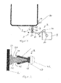
- FIG. 1 schematically shows a device 1 for determining the position of a metallurgical vessel 2 in a metallurgical plant.
- a positioning means 4 is arranged at the end of the arm of a robot 3, which can be brought to determine the position of the metallurgical vessel 2 in space with a, disposed on the metallurgical vessel 2 position element 20 into engagement. If the position means 4 and the position element 20 are in engagement, the position or the position of the metallurgical vessel 2 in the space or with respect to the robot coordinates can be determined on the basis of the knowledge of the coordinates of the position means 4.
- FIG. 1 shows a metallurgical vessel 2, which finds application in a metallurgical plant.
- the metallurgical vessel 2 can be, for example, a steel ladle or a steel distribution vessel (tundish).
- two positioning elements 20 are arranged, which can be brought to the determination of the position of the metallurgical vessel in space with the positioning means 4 in engagement.
- the position elements 20 have a conical shape, wherein the base surface of the position element merges into a flange 24, which is flanged to the surface of the outside of the metallurgical vessel 2.
- the flange 24 is connected to the metallurgical vessel 2 via a welded connection.
- the flange 24 of the position element 20 may also be connected to the metallurgical vessel 2 via a rivet or a screw connection.
- the position elements 20 are made of a heat-resistant material, preferably a steel alloy. This can ensure that even at high temperatures, starting from the contents of the metallurgical vessel 2, the position elements 20 are suitable for position determination.
- FIG. 1 further shows a robot 3, which has four joints 30 and three arm segments 32.
- the joints 30 of the robot 3 are designed such that the positioning means 4 can be moved or pivoted in space, so that it can always be brought into engagement with the position elements 20.
- the robot 3 is preferably a six-axis robot which has six axes of rotation.
- the joints 30, which can preferably be pivoted in each case about an axis of rotation, have position sensors which measure the angle of rotation of a joint 30 about a corresponding axis of rotation.
- the angular positions of the respective joints 30 determined via the position sensors are combined in an evaluation unit 5.
- the positioning means 4 is connected to the outermost joint 30 of the robot 3 via flanges 48 and 40.
- the positioning means 4 and the flanges 40 and 48 are made of metal, preferably a steel alloy.
- the positioning means 4 has a hollow conical shape, wherein the tip of the hollow cone of the positioning means 4 merges into a flange 48, which is connected to the flange 40.
- the contact surfaces 22 and 44 of the position element 20 and the position means 4 have smooth, low-friction surfaces, which favor a nesting or engagement of the position element 20 with the position means 4.
- a touch sensor 42 Arranged on the flange 40 is a touch sensor 42, which serves to measure the forces and moments acting on the positioning means 4 when in contact with the position element 20. The measured values of the touch sensor 42 are forwarded to the evaluation unit 5.
- the evaluation unit 5 is able to determine a new measurement position of the position means 4 based on the measurement data based on the collision of the position means 4 with the position element 20, wherein the evaluation unit 5 pursues the goal of pushing the position means 4 further over the position element 20 , Consequently, after each contacting of the contact surfaces 22 or 44 of the position element 20 or of the position means 4, the contact is released and attempts to move the position means 4 further over the position element 20.
- the positioning means 4 on the position element 22 can reach an end position in which the positioning means 4 is fully engaged with the position element 20.
- FIG. 2 schematically is a detail view of the positioning means 4 and the position element 20 can be seen.
- position means 4 and position element 20 are about to engage with each other.
- evaluation unit 5 can then via the position sensors the joints 30 of the robot 3 determine the position of the positioning means 40 and thus the position of the metallurgical vessel 2 in space.
- the measuring process described above can be performed on at least two different measuring elements 20.
- the at least two different measuring elements at the same or, as in Fig. 1 shown to be attached to different surfaces of the metallurgical vessel.
Landscapes
- Engineering & Computer Science (AREA)
- Mechanical Engineering (AREA)
- Physics & Mathematics (AREA)
- General Physics & Mathematics (AREA)
- Human Computer Interaction (AREA)
- Robotics (AREA)
- Manipulator (AREA)
Description
- Die vorliegende Erfindung betrifft eine Vorrichtung sowie ein Verfahren, welche zur Positionsbestimmung eines metallurgischen Gefäßes dienen.
- In Hüttenwerken, wie auch Walzwerken, kommt es vermehrt zum Einsatz von Robotern. Diese kommen insbesondere für Arbeiten zum Einsatz, welche eine unzumutbare körperliche Belastung für einen Bediener darstellen oder diesen gefährden würden. Insbesondere die Handhabung von metallurgischen Gefäßen, wie zum Beispiel Stahlgießpfannen oder Stahlverteilergefäße (Tundishe) erfordern Arbeitsschritte, für welche ein unmittelbarer Einsatz eines Bedieners vermieden werden soll. Entsprechend werden derartige Aufgaben von Robotern übernommen.
- Die Handhabung metallurgischer Gefäße unter Verwendung von Robotern erfordert eine genaue Kenntnis der Lage der metallurgischen Gefäße im Raum. Jedoch herrschen bei den Prozessen, bei welchen metallurgische Gefäße zum Einsatz kommen, Toleranzen im Dezimeterbereich, was eine genaue Lagebestimmung der metallurgischen Gefäße im Raum notwendig macht. Folglich müssen diese Toleranzen zunächst manuell ausgeglichen werden. Dies hat beispielsweise zur Folge, dass der Manipulator oder Roboter zunächst manuell an dem metallurgischen Gefäß positioniert werden muss, bevor ein Arbeitsschritt mit dem Roboter durchgeführt werden kann. Muss sich der Bediener dazu in die Nähe des metallurgischen Gefäßes begeben, beseht eine erhöhte gesundheitliche Gefährdung des Bedieners. Muss der Bediener den Roboter manuell über eine Steuervorrichtung in Position bringen, wirkt sich dies negativ auf Prozess- und/oder Zykluszeiten aus.
- Es ist bekannt, dass zum Zwecke der Automatisierung der Positionierung eines Roboters an einem metallurgischen Gefäß optische Sensoren eingesetzt werden. Die
WO 2008/025562 A1 zeigt beispielsweise eine an einem Roboter angeordnete Kamera, welche in der Lage ist, die Pfannenlage zu erkennen. Der Einsatz von optischen Sensoren in unmittelbarer Nähe zu metallurgischen Gefäßen kann jedoch aufgrund der vorherrschenden Umgebungsbedingungen zu Ungenauigkeiten beziehungsweise zu einer unzuverlässigen Datenermittlung führen und sich negativ auf die Stabilität des Prozesses auswirken. - Ausgehend von dem bekannten Stand der Technik ist es eine Aufgabe der vorliegenden Erfindung, eine Vorrichtung und ein Verfahren zur Positionsbestimmung eines metallurgischen Gefäßes anzugeben, welche die Positionsbestimmung des metallurgischen Gefäßes verbessert.
- Diese Aufgabe wird mittels einer Vorrichtung mit den Merkmalen des Anspruchs 1 gelöst. Vorteilhafte Ausgestaltungen ergeben sich aus den Unteransprüchen.
- Der Begriff Positionssensor ist in der vorliegenden Beschreibung bevorzugt als ein Sensor zur Bestimmung von Drehwinkeln oder Drehpositionen zu verstehen.
- Entsprechend wird eine Vorrichtung zur Positionsbestimmung eines metallurgischen Gefäßes angegeben, welche erfindungsgemäß einen Roboter mit einem Positionsmittel zum Ineingriffbringen mit einem am metallurgischen Gefäß angeordneten Positionselement zur Positionsbestimmung umfasst.
- Dadurch kann die Position des metallurgischen Gefäßes im Raum exakt bestimmt werden und der Einsatz eines Bedieners zur Positionsbestimmung des metallurgischen Gefäßes ist nicht mehr erforderlich. Insbesondere wird ein Bediener nicht den Gefahren in der unmittelbaren Umgebung des metallurgischen Gefäßes ausgesetzt. Darüber hinaus können Arbeitskosten eingespart werden.
- Die Positionsbestimmung über den Kontakt zwischen dem Positionsmittel und dem Positionselement ermöglicht auch unter den Umgebungsbedingungen eines metallurgischen Gefäßes zuverlässige Ergebnisse.
- Beispielsweise kann so eine erfolgreiche Positionsbestimmung unabhängig von einer von dem metallurgischen Gefäß ausgehenden Dampfbildung oder Rauchentwicklung durchgeführt werden.
- In einer bevorzugten Weiterbildung umfasst das Positionsmittel einen Tastsensor.
- Dadurch kann festgestellt werden, ob beziehungsweise wann das Positionsmittel mit einem anderen Gegenstand, bevorzugt mit dem Positionselement, in Kontakt tritt.
- In einer bevorzugten Weiterbildung ist der Tastsensor dazu eingerichtet, auf das Positionsmittel wirkende Kräfte und Momente zu messen.
- Dadurch kann die Lage des Positionsmittels zu einem anderen Gegenstand, insbesondere dem Positionselement, bei Kontakt ermittelt werden. Sind Positionsmittel und Positionselement durch den Roboter beispielsweise nicht exakt in Eingriff gebracht, so kann anhand der auf das Positionsmittel wirkenden, über den Tastsensor ermittelten Kräfte und Momente, die Position des Positionsmittels bezüglich des Positionselements bestimmt werden. Entsprechend kann der Roboter aufgrund des Tastsensors automatisch in die Position des Positionselements verfahren werden, so dass auf diese Weise auch die Position des metallurgischen Gefäßes bestimmt werden kann.
- In einer weiter bevorzugten Ausführungsform umfasst die Vorrichtung eine Auswerteeinheit, welche dazu eingerichtet ist, ausgehend von den Messdaten des Tastsensors eine neue Messposition des Positionsmittels zu bestimmen.
- Dadurch kann sich dem Ineingriffbringen des Positionsmittels mit dem Positionselement schrittweise genähert werden. Anhand der bei einem Positionsmessvorgang mittels des Tastsensors ermittelten Kräfte und Momente, welche bei Kontakt mit dem Positionselement auf das Positionsmittel wirken, kann ermittelt werden, in welche Richtung, um welche Distanz das Positionsmittel durch den Roboter relativ zur aktuellen Messposition verfahren werden muss, um das Positionsmittel mit dem Positionselement in Eingriff zu bringen, oder sich dem Zustand des Eingriffs anzunähern.
- In einer bevorzugten Ausgestaltung ist das Positionsmittel dazu eingerichtet, mit dem Positionselement beim Ineingriffbringen eine vorbestimmte Endposition einzunehmen.
- Dadurch kann festgestellt werden, ob beziehungsweise wann das Positionsmittel mit dem Positionselement des metallurgischen Gefäßes vollständig in Eingriff gebracht ist. In dem Zustand, in dem das Positionsmittel und das Positionselement vollständig in Eingriff gebracht sind, wirket ein vorbestimmtes Bild von Kräften beziehungsweise Momenten auf den Tastsensor, welches die Endposition zwischen dem Positionsmittel und dem Positionselement repräsentiert. Bevorzugt wirkt in der Endposition nur ein Kraftvektor entlang eines Freiheitsgrades auf den Tastsensor des Positionsmittels.
- In einer bevorzugten Weiterbildung ist das Positionsmittel komplementär zu dem Positionselement ausgeführt.
- Dadurch können das Positionsmittel und das Positionselement miteinander in Eingriff gebracht werden. Beispielsweise kann das Positionsmittel als weiblicher Teil und das Positionselement als männlicher Teil ausgeführt sein. Dabei sind Positionsmittel und Positionselement nur in einer Endposition vollständig in Eingriff gebracht.
- In einer weiter bevorzugten Ausführungsform weisen das Positionsmittel und das Positionselement eine konische Form auf.
- Dadurch wird das Ineingriffbringen des Positionsmittels mit dem Positionselement begünstigt. Insbesondere im Fall des Aufeinandertreffens von komplementären konischen Oberflächen des Positionsmittels und des Positionselements, wird das Ineingriffbringen, und somit die Einnahme einer Endposition, gefördert.
- In einer bevorzugten Ausgestaltung ist das Positionsmittel hohlkegelförmig und/oder das Positionselement kegelförmig.
- Dadurch kann die Lage im Raum des metallurgischen Gefäßes bis auf einen Freiheitsgrad eindeutig bestimmt werden. Bei einem unbestimmten Freiheitsgrad handelt es sich dabei um die Drehachse, welche koaxial zu der Höhe des Kegels, bevorzugt eines geraden Kreiskegels, verläuft. Wird beispielsweise an der Unterseite des metallurgischen Gefäßes gemessen und ist das metallurgische Gefäß drehfest um eine Achse gelagert, die mit den Achsen von Positionselement und Positionsmittel zusammenfällt und in deren Richtung das Positionselement und das Positionsmittel miteinander in Eingriff gebracht werden, so kann die oben beschriebene Messanordnung ausreichen, um die Lage des metallurgischen Gefäßes im Raum sowie die Lage von an dem metallurgischen Gefäß angebrachten Funktionselementen eindeutig zu bestimmen.
- Bevorzugt weist das metallurgische Gefäß ein zweites hohlkegelförmiges Positionselement auf, wodurch ein zunächst unbestimmter Freiheitsgrad der Rotationsachse, welche koaxial zur Höhe des Hohlkegels des Positionselements beziehungsweise des Kegels des Positionsmittels verläuft, bestimmt werden kann. Die drehfeste Anordnung des metallurgischen Gefäßes um eine Achse, die mit den Achsen von Positionselement und Positionsmittel zusammenfällt und in deren Richtung das Positionselement und das Positionsmittel miteinander in Eingriff gebracht werden, ist somit nicht erforderlich.
- In einer bevorzugten Ausgestaltung weist das Positionsmittel und/oder das Positionselement Vertiefungen auf.
- Dadurch können Fremdkörper, wie beispielsweise Schmutz, die sich auf den Kontaktoberflächen des Positionsmittels und des Positionselements befinden, aufgenommen werden. Beispielsweise kann eine Anhaftung auf den Kontaktflächen durch Kontakt und Bewegung des Positionsmittels und des Positionselements gegeneinander abgestreift und in einer der Vertiefungen oder Aussparungen aufgenommen werden oder durch sie hindurchfallen. Somit kann sichergestellt werden, dass das Ineingriffbringen von Positionsmittel und Positionselement nicht behindert oder gestört wird.
- In einer Weiterbildung umfasst der Roboter Positionssensoren an seinen Gelenken.
- Dadurch ist die Lage des Roboters im Raum, insbesondere die des den Manipulator oder Roboter bildenden Positionsmittels, zu jeder Zeit bekannt. Sind Positionsmittel des Roboters und Positionselemente des metallurgischen Gefäßes vollständig in Eingriff gebracht, so kann die Lage des an dem metallurgischen Gefäß angebrachten Positionselements bestimmt werden.
- Berühren sich Positionsmittel und Positionselement infolge einer Roboterbewegung ohne sich dabei im Eingriff miteinander zu befinden, so kann anhand der von der Berührung ausgehenden Kräfte beziehungsweise Momente in Verbindung mit der Information der Positionssensoren eine neue sinnvolle Messposition ermittelt werden. Nach diesem Prinzip kann das Positionsmittel mit Hilfe des Roboters schrittweise an den Eingriff mit dem Positionselement herangetastet werden.
- Ist das metallurgische Gefäß drehfest gelagert oder besitzen das Positionselement und das Positionsmittel nach dem Ineingriffbringen in ihrer Endposition keinen rotatorischen Freiheitsgrad, so genügt die Positionsmessung mittels der Positionssensoren des Roboters an einem Positionselement des metallurgischen Gefäßes zur eindeutigen Bestimmung der Lage des metallurgischen Gefäßes im Raum. Ist das metallurgische Gefäß nicht drehfest gelagert oder besitzen das Positionselement und das Positionsmittel nach dem Ineingriffbringen in ihrer Endposition zumindest einen rotatorischen Freiheitsgrad, so ist zur vollständigen Bestimmung der Lage des metallurgischen Gefäßes im Raum zumindest eine weitere Positionsmessung mittels der Positionssensoren des Roboters an einem weiteren, an dem metallurgischen Gefäß angebrachten Positionselement nötig, um die Lage des metallurgischen Gefäßes im Raum eindeutig zu bestimmen.
- Die Positionssensoren sind in der Regel in den Gelenken eines Roboterarms angebracht, und sind in der Lage, eine kinematische Kette, bestehend aus einzelnen Gliedern des Roboters, zu bestimmen.
- In einer weiter bevorzugten Ausführungsform umfasst das Positionsmittel und/oder das Positionselement Kontaktflächen, deren Kanten Phasen aufweisen.
- Dadurch wird ein Ineinanderführen des Positionsmittels und des Positionselements begünstigt. Die Phasen an den Kanten der Kontaktflächen des Positionsmittels und des Positionselements ermöglichen, dass bei einer Bewegung des Positionsmittels durch den Roboter ein Gleiten auf der Kontaktoberfläche des Positionselements unterstützt wird. Das Positionsmittel kann somit die Oberfläche des Positionselements abtasten, bis es die Endposition erreicht hat, ohne dabei vorher mit dem Positionselement zu verkeilen.
- Die oben genannte Aufgabe wird auch durch ein metallurgisches Gefäß mit den Merkmalen des Anspruchs 12 gelöst.
- Entsprechend umfasst ein metallurgisches Gefäß eines Hüttenwerks ein Positionselement zum Ineingriffbringen mit einem Positionsmittel zur Bestimmung der Position des metallurgischen Gefäßes.
- Dadurch kann die Lage des metallurgischen Gefäßes im Raum bestimmt werden.
- Bevorzugt können auch mindestens zwei Positionselemente an dem metallurgischen Gefäß angeordnet sein. Dadurch wird eine eindeutige Bestimmung der Lage des metallurgischen Gefäßes im Raum auch dann ermöglicht, wenn das metallurgische Gefäß gegen eine Rotation um eine Messachse senkrecht zur Oberfläche des metallurgischen Gefäßes, an der sich die Positionselemente befinden, nicht gesichert ist.
- Die oben genannte Aufgabe wird auch durch ein System mit den Merkmalen des Anspruchs 13 gelöst.
- Mit Hilfe dieses Systems werden die oben bezüglich der Vorrichtung und dem metallurgischen Gefäß dargestellten Vorteile erreicht.
- Die oben genannte Aufgabe wird auch durch ein Verfahren mit den Merkmalen des Anspruchs 14 gelöst. Entsprechend umfasst das Verfahren zur Positionsbestimmung eines metallurgischen Gefäßes mittels einer Vorrichtung gemäß einem der Ansprüche 1 bis 11, dass ein Positionsmittel eines Roboters zur Positionsbestimmung mit einem, am metallurgischen Gefäß angeordneten Positionselement in Eingriff gebracht wird.
- Eine vorteilhafte Ausgestaltung dieses Verfahrens ergibt sich aus dem Unteranspruch.
- Entsprechend wird ein Positionsmessvorgang iterativ ausgeführt, bis zwischen Positionsmittel und Positionselement eine definierte Endposition erreicht wird.
- So können das Positionsmittel und das Positionselement schrittweise in Eingriff gebracht werden. Dabei tastet das Positionsmittel das metallurgische Gefäß, bevorzugt das auf dem metallurgischen Gefäß angebrachte Positionselement ab, bis es die Endposition erreicht hat.
- Bevorzugte weitere Ausführungsformen und Aspekte der vorliegenden Erfindung werden durch die nachfolgende Beschreibung der Figuren näher erläutert. Dabei zeigen:
- Figur 1
- schematisch eine Vorrichtung zur Positionsbestimmung eines metallurgischen Gefäßes, und
- Figur 2
- schematisch eine Detailansicht eines Positionselements und eines Positionsmittels einer Vorrichtung zur Positionsbestimmung eines metallurgischen Gefäßes.
- Im Folgenden werden bevorzugte Ausführungsbeispiele anhand der Figuren beschrieben. Dabei werden gleiche, ähnliche oder gleichwirkende Elemente mit identischen Bezugszeichen bezeichnet. Um Redundanzen zu vermeiden, wird auf eine wiederholte Beschreibung dieser Elemente in der nachfolgenden Beschreibung teilweise verzichtet.
-
Figur 1 zeigt schematisch eine Vorrichtung 1 zur Positionsbestimmung eines metallurgischen Gefäßes 2 in einem Hüttenwerk. Dabei ist am Ende des Arms eines Roboters 3 ein Positionsmittel 4 angeordnet, welches zur Bestimmung der Lage des metallurgischen Gefäßes 2 im Raum mit einem, an dem metallurgischen Gefäß 2 angeordneten Positionselement 20 in Eingriff gebracht werden kann. Befinden sich das Positionsmittel 4 und das Positionselement 20 in Eingriff, so kann auf der Grundlage der Kenntnis der Koordinaten des Positionsmittels 4 die Position beziehungsweise die Lage des metallurgischen Gefäßes 2 im Raum beziehungsweise bezüglich der Roboterkoordinaten bestimmt werden. -
Figur 1 zeigt ein metallurgisches Gefäß 2, welches in einem Hüttenwerk Anwendung findet. Dabei kann es sich bei dem metallurgischen Gefäß 2 beispielsweise um eine Stahlgießpfanne oder ein Stahlverteilergefäß (Tundish) handeln. Auf der Außenseite des metallurgischen Gefäßes 2 sind zwei Positionselemente 20 angeordnet, welche zur Bestimmung der Lage des metallurgischen Gefäßes im Raum mit dem Positionsmittel 4 in Eingriff gebracht werden können. Die Positionselemente 20 weisen eine kegelförmige Form auf, wobei die Grundfläche des Positionselements in einen Flansch 24 übergeht, welcher an der Oberfläche der Außenseite des metallurgischen Gefäßes 2 angeflanscht ist. Dabei ist der Flansch 24 mit dem metallurgischen Gefäß 2 über eine Schweißverbindung verbunden. Alternativ kann der Flansch 24 des Positionselements 20 auch über eine Niet- oder eine Schraubverbindung mit dem metallurgischen Gefäß 2 verbunden sein. - Darüber hinaus bestehen die Positionselemente 20 aus einem hitzebeständigen Material, bevorzugt einer Stahllegierung. Dadurch kann sichergestellt werden, dass auch bei hohen Temperaturen, ausgehend von dem Inhalt des metallurgischen Gefäßes 2, die Positionselemente 20 zur Positionsbestimmung geeignet sind.
-
Figur 1 zeigt weiterhin einen Roboter 3, welcher vier Gelenke 30 sowie drei Armsegmente 32 aufweist. Dabei sind die Gelenke 30 des Roboters 3 derart ausgebildet, dass das Positionsmittel 4 im Raum verfahren beziehungsweise verschwenkt werden kann, so dass es stets mit den Positionselementen 20 in Eingriff gebracht werden kann. Bevorzugt handelt es sich bei dem Roboter 3 um einen Sechs-Achs-Roboter, welcher sechs Rotationsachsen aufweist. - Die Gelenke 30, welche bevorzugt jeweils um eine Rotationsachse verschwenkt werden können, weisen Positionssensoren auf, welche den Drehwinkel eines Gelenks 30 um eine entsprechende Rotationsachse messen. Die über die Positionssensoren ermittelten Winkelstellungen der jeweiligen Gelenke 30 werden in einer Auswerteeinheit 5 zusammengeführt. Durch die Kenntnis der Geometrie der Bestandteile des Roboters 3 sowie der Winkelstellung der einzelnen Gelenke 30 können die Koordinaten des am Roboter 3 angebrachten Positionsmittels 4 bestimmt werden.
- Das Positionsmittel 4 ist über Flansche 48 und 40 mit dem äußersten Gelenk 30 des Roboters 3 verbunden. Das Positionsmittel 4 und die Flansche 40 und 48 sind dabei aus Metall, bevorzugt einer Stahllegierung, gefertigt.
- Das Positionsmittel 4 weist eine hohlkegelförmige Form auf, wobei die Spitze des Hohlkegels des Positionsmittels 4 in einen Flansch 48 übergeht, welcher mit dem Flansch 40 verbunden ist.
- Die Kontaktflächen 22 beziehungsweise 44 des Positionselements 20 beziehungsweise des Positionsmittels 4 weisen glatte, reibungsarme Oberflächen auf, welche ein Ineinanderführen beziehungsweise Ineingriffbringen des Positionselements 20 mit dem Positionsmittel 4 begünstigen.
- An dem Flansch 40 ist ein Tastsensor 42 angeordnet, welcher dazu dient, die auf das Positionsmittel 4 bei Kontakt mit dem Positionselement 20 wirkenden Kräfte und Momente zu messen. Die Messwerte des Tastsensors 42 werden an die Auswerteeinheit 5 weitergegeben.
- Bewegt der Roboter 3 das Positionsmittel 4 über das Positionselement 20, so dass die Kontaktflächen 22 beziehungsweise 44 des Positionselements 20 beziehungsweise des Positionsmittels 4 kollidieren, können die von der Kollision auf das Positionsmittel 4 wirkenden Kräfte beziehungsweise Momente an dem Tastsensor 22 gemessen werden. Die Auswerteeinheit 5 ist dabei in der Lage, anhand der auf der Kollision des Positionsmittels 4 mit dem Positionselement 20 basierenden Messdaten eine neue Messposition des Positionsmittels 4 zu bestimmen, wobei die Auswerteeinheit 5 das Ziel verfolgt, das Positionsmittel 4 weiter über das Positionselement 20 zu schieben. Folglich wird nach jedem Inkontakttreten der Kontaktflächen 22 beziehungsweise 44 des Positionselements 20 beziehungsweise des Positionsmittels 4 der Kontakt gelöst und versucht, das Positionsmittel 4 weiter über das Positionselement 20 zu verfahren.
- Durch eine iterative Ausführung der oben beschriebenen Vorgehensweise kann das Positionsmittel 4 auf dem Positionselement 22 eine Endposition erreichen, in welcher das Positionsmittel 4 mit dem Positionselement 20 vollständig in Eingriff ist.
-
Figur 2 ist schematisch eine Detailansicht des Positionsmittels 4 sowie des Positionselements 20 zu entnehmen. Dabei sind Positionsmittel 4 und Positionselement 20 kurz davor, miteinander in Eingriff zu gelangen. - Wird die Endposition erreicht, stellt sich am Tastsensor 42 ein vorbestimmtes Bild von auf das Positionsmittel 4 wirkenden Kräften beziehungsweise Momenten ein. Die in
Figur 1 gezeigte Auswerteeinheit 5 kann dann über die Positionssensoren der Gelenke 30 des Roboters 3 die Lage des Positionsmittels 40 und somit die Lage des metallurgischen Gefäßes 2 im Raum bestimmen. - Ist die Lage des metallurgischen Gefäßes bezüglich einer Drehachse, welche orthogonal zur Oberfläche des metallurgischen Gefäßes 2, an dem sich ein Positionselement befindet, verläuft, nicht bekannt, so kann der oben beschriebene Messvorgang an mindestens zwei unterschiedlichen Messelementen 20 durchgeführt werden. Hierbei können die mindestens zwei unterschiedlichen Messelemente an der gleichen oder, wie in
Fig. 1 gezeigt, an unterschiedlichen Oberflächen des metallurgischen Gefäßes angebracht sein. - Soweit anwendbar, können alle einzelnen Merkmale, die in den einzelnen Ausführungsbeispielen dargestellt sind, miteinander kombiniert und/oder ausgetauscht werden, ohne den Bereich der Erfindung zu verlassen.
-
- 1
- Vorrichtung
- 2
- Metallurgisches Gefäß
- 20
- Positionselement
- 22
- Kontaktfläche
- 24
- Flansch
- 3
- Roboter
- 30
- Gelenk
- 32
- Armsegment
- 4
- Positionsmittel
- 40
- Flansch
- 42
- Tastsensor
- 44
- Kontaktfläche
- 46
- Fase
- 48
- Flansch
- 5
- Auswerteeinheit
Claims (15)
- Vorrichtung (1) zur Positionsbestimmung eines metallurgischen Gefäßes (2),
gekennzeichnet durch
einen Roboter (3) mit einem Positionsmittel (4) zum Ineingriffbringen mit einem am metallurgischen Gefäß (2) angeordneten Positionselement (20) zur Positionsbestimmung. - Vorrichtung (1) gemäß Anspruch 1, dadurch gekennzeichnet, dass das Positionsmittel (4) komplementär zu dem Positionselement (20) ausgeführt ist.
- Vorrichtung (1) gemäß Anspruch 1 oder 2, dadurch gekennzeichnet, dass das Positionsmittel (4) einen Tastsensor (42) umfasst.
- Vorrichtung (1) gemäß einer der vorausgegangenen Ansprüche, dadurch gekennzeichnet, dass der Tastsensor (42) dazu eingerichtet ist, auf das Positionsmittel (4) wirkende Kräfte und Momente zu messen.
- Vorrichtung (1) gemäß Anspruch 3 oder 4, dadurch gekennzeichnet, dass die Vorrichtung (1) eine Auswerteeinheit (5) umfasst, welche dazu eingerichtet ist, ausgehend von den Messdaten des Tastsensors (42) eine neue Messposition des Positionsmittels (4) zu Bestimmen.
- Vorrichtung (1) gemäß einem der vorhergehenden Ansprüche, dadurch gekennzeichnet, dass Positionsmittel (4) dazu eingerichtet ist, mit dem Positionselement (20) beim Ineingriffbringen eine vorbestimmte Endposition einzunehmen.
- Vorrichtung (1) gemäß einem der vorhergehenden Ansprüche, dadurch gekennzeichnet, dass das Positionsmittel (4) und das Positionselement (20) eine konische Form aufweisen.
- Vorrichtung (1) gemäß einem der vorhergehenden Ansprüche, dadurch gekennzeichnet, dass das Positionsmittel (4) kegelförmig und/oder das Positionselement (20) hohlkegelförmig ist.
- Vorrichtung (1) gemäß einem der vorhergehenden Ansprüche, dadurch gekennzeichnet, dass das Positionsmittel (4) und/oder das Positionselement (20) Vertiefungen oder Aussparungen aufweisen.
- Vorrichtung (1) gemäß einem der vorhergehenden Ansprüche, dadurch gekennzeichnet, dass der Roboter (3) Positionssensoren an seinen Gelenken (30) umfasst.
- Vorrichtung (1 gemäß einem der vorhergehenden Ansprüche, dadurch gekennzeichnet, dass das Positionsmittel (4) und/oder das Positionselement (20) Kontaktflächen (22, 44) umfasst, deren Kanten Fasen (46) aufweisen.
- Metallurgisches Gefäß (2) eines Hüttenwerks,
gekennzeichnet durch
ein Positionselement (20) zum Ineingriffbringen mit einem Positionsmittel (4) zur Bestimmung der Position des metallurgischen Gefäßes (2). - System bestehend aus einer Vorrichtung (1) zur Positionsmessung eines metallurgischen Gefäßes (2) gemäß einem der Ansprüche 1 bis 11 sowie einem metallurgischen Gefäß (2) gemäß Anspruch 12.
- Verfahren zur Positionsbestimmung eines metallurgischen Gefäßes (2) mittels einer Vorrichtung (1) gemäß einem der Ansprüche 1 bis 11, dadurch gekennzeichnet, dass
das ein Positionsmittel (4) eines Roboters (3) zur Positionsbestimmung mit einem am metallurgischen Gefäß (2) angeordneten Positionselement (20) in Eingriff gebracht wird. - Verfahren gemäß Anspruch 14, dadurch gekennzeichnet, dass ein Positionsmessvorgang iterativ ausgeführt wird, bis zwischen Positionsmittel (4) und Positionselement (20) eine definierte Endposition erreicht wird.
Applications Claiming Priority (2)
| Application Number | Priority Date | Filing Date | Title |
|---|---|---|---|
| DE102012018568 | 2012-09-20 | ||
| DE102012224343.7A DE102012224343A1 (de) | 2012-09-20 | 2012-12-21 | Vorrichtung zur Positionsbestimmung eines metallurgischen Gefäßes |
Publications (3)
| Publication Number | Publication Date |
|---|---|
| EP2711108A2 true EP2711108A2 (de) | 2014-03-26 |
| EP2711108A3 EP2711108A3 (de) | 2017-11-15 |
| EP2711108B1 EP2711108B1 (de) | 2020-07-08 |
Family
ID=49182058
Family Applications (1)
| Application Number | Title | Priority Date | Filing Date |
|---|---|---|---|
| EP13183371.7A Active EP2711108B1 (de) | 2012-09-20 | 2013-09-06 | System und Verfahren zur Positionsbestimmung eines metallurgischen Gefäßes |
Country Status (2)
| Country | Link |
|---|---|
| EP (1) | EP2711108B1 (de) |
| DE (1) | DE102012224343A1 (de) |
Cited By (1)
| Publication number | Priority date | Publication date | Assignee | Title |
|---|---|---|---|---|
| CN113165059A (zh) * | 2019-03-04 | 2021-07-23 | 黑崎播磨株式会社 | 板保持装置、板拆卸装置、板安装装置及板装拆装置 |
Citations (1)
| Publication number | Priority date | Publication date | Assignee | Title |
|---|---|---|---|---|
| WO2008025562A1 (de) | 2006-09-01 | 2008-03-06 | Stopinc Aktiengesellschaft | Anlage zur wartung eines am ausguss eines behälters für metallschmelze montierten schiebeverschlusses |
Family Cites Families (1)
| Publication number | Priority date | Publication date | Assignee | Title |
|---|---|---|---|---|
| DE102010032879A1 (de) * | 2010-07-30 | 2012-02-02 | Daimler Ag | Verfahren zum Manipulieren eines Objekts |
-
2012
- 2012-12-21 DE DE102012224343.7A patent/DE102012224343A1/de not_active Withdrawn
-
2013
- 2013-09-06 EP EP13183371.7A patent/EP2711108B1/de active Active
Patent Citations (1)
| Publication number | Priority date | Publication date | Assignee | Title |
|---|---|---|---|---|
| WO2008025562A1 (de) | 2006-09-01 | 2008-03-06 | Stopinc Aktiengesellschaft | Anlage zur wartung eines am ausguss eines behälters für metallschmelze montierten schiebeverschlusses |
Cited By (1)
| Publication number | Priority date | Publication date | Assignee | Title |
|---|---|---|---|---|
| CN113165059A (zh) * | 2019-03-04 | 2021-07-23 | 黑崎播磨株式会社 | 板保持装置、板拆卸装置、板安装装置及板装拆装置 |
Also Published As
| Publication number | Publication date |
|---|---|
| DE102012224343A1 (de) | 2014-03-20 |
| EP2711108B1 (de) | 2020-07-08 |
| EP2711108A3 (de) | 2017-11-15 |
Similar Documents
| Publication | Publication Date | Title |
|---|---|---|
| DE102018116053B4 (de) | Robotersystem und Roboterlernverfahren | |
| EP4046755B1 (de) | Vorrichtung und verfahren zum automatisierten entnehmen von in einem behälter angeordneten werkstücken | |
| EP3108311B1 (de) | Verfahren, bearbeitungsmaschine und computerprogrammprodukt zum bildbasierten platzieren von werkstückbearbeitungsvorgängen | |
| EP2546711B1 (de) | Verfahren zum Programmieren eines Roboters | |
| DE102015105687B4 (de) | Roboter | |
| DE102018213985B4 (de) | Robotersystem | |
| DE102008063680A1 (de) | Verfahren zum Einlernen (Teachen) eines Industrieroboters sowie ein entsprechend ausgestatteter Industrieroboter | |
| DE102015001579B4 (de) | Robotersystem mit Vermeidung unbeabsichtigten Abwurfs geförderter Gegenstände | |
| DE102009051153A1 (de) | Industrieroboter mit sensorischer Assistenz | |
| DE102017108492B4 (de) | Steuervorrichtung eines Roboters, die ein Betriebsprogramm, in dem der Zustand einer zusätzlichen Achse enthalten ist, anzeigt | |
| EP2566667A1 (de) | Handgerät und verfahren zum steuern und/oder programmieren eines manipulators | |
| DE202010005418U1 (de) | Kalibriereinrichtung | |
| DE112018003597T5 (de) | Greifsystem | |
| WO2018109233A1 (de) | Automatisiertes verbinden und trennen zweier fluidleitungen | |
| EP3441200A1 (de) | Referenzierverfahren und vorrichtung für industrieroboter | |
| EP2458135B1 (de) | Verfahren und Vorrichtung zur halbautomatischen Justierung einer Handhabungseinrichtung | |
| EP2711108B1 (de) | System und Verfahren zur Positionsbestimmung eines metallurgischen Gefäßes | |
| EP2666955B1 (de) | Verfahren und Vorrichtung zur halbautomatischen Justierung einer Handhabungseinrichtung | |
| EP3253540B1 (de) | Verfahren zum justieren eines drehmomentsensors eines roboterarms und roboter mit einem roboterarm und einer steuervorrichtung | |
| DE102019120157B3 (de) | Verifikation eines Massemodells eines Robotermanipulators | |
| WO2020161037A1 (de) | Kombinieren zweier einzelner robotermanipulatoren zu einem robotersystem durch kalibrieren | |
| DE102019107964B3 (de) | Projektionseinrichtung für einen Robotermanipulator | |
| DE102018004947B3 (de) | Verfahren zur Steuerung von Antrieben eines Roboters und Robotersystem | |
| DE102016110877A1 (de) | Verfahren zum Befestigen einer mobilen Werkzeugmaschine und mobile Werkzeugmaschine | |
| AT528365B1 (de) | Kransystem zum Heben von Lasten |
Legal Events
| Date | Code | Title | Description |
|---|---|---|---|
| PUAI | Public reference made under article 153(3) epc to a published international application that has entered the european phase |
Free format text: ORIGINAL CODE: 0009012 |
|
| 17P | Request for examination filed |
Effective date: 20130906 |
|
| AK | Designated contracting states |
Kind code of ref document: A2 Designated state(s): AL AT BE BG CH CY CZ DE DK EE ES FI FR GB GR HR HU IE IS IT LI LT LU LV MC MK MT NL NO PL PT RO RS SE SI SK SM TR |
|
| AX | Request for extension of the european patent |
Extension state: BA ME |
|
| RAP1 | Party data changed (applicant data changed or rights of an application transferred) |
Owner name: SMS GROUP GMBH |
|
| REG | Reference to a national code |
Ref country code: DE Ref legal event code: R079 Ref document number: 502013014885 Country of ref document: DE Free format text: PREVIOUS MAIN CLASS: B22D0046000000 Ipc: B22D0041560000 |
|
| PUAL | Search report despatched |
Free format text: ORIGINAL CODE: 0009013 |
|
| AK | Designated contracting states |
Kind code of ref document: A3 Designated state(s): AL AT BE BG CH CY CZ DE DK EE ES FI FR GB GR HR HU IE IS IT LI LT LU LV MC MK MT NL NO PL PT RO RS SE SI SK SM TR |
|
| AX | Request for extension of the european patent |
Extension state: BA ME |
|
| RIC1 | Information provided on ipc code assigned before grant |
Ipc: B25J 13/08 20060101ALI20171009BHEP Ipc: B22D 41/56 20060101AFI20171009BHEP Ipc: B22D 46/00 20060101ALI20171009BHEP |
|
| STAA | Information on the status of an ep patent application or granted ep patent |
Free format text: STATUS: EXAMINATION IS IN PROGRESS |
|
| 17Q | First examination report despatched |
Effective date: 20180103 |
|
| RBV | Designated contracting states (corrected) |
Designated state(s): AL AT BE BG CH CY CZ DE DK EE ES FI FR GB GR HR HU IE IS IT LI LT LU LV MC MK MT NL NO PL PT RO RS SE SI SK SM TR |
|
| GRAP | Despatch of communication of intention to grant a patent |
Free format text: ORIGINAL CODE: EPIDOSNIGR1 |
|
| STAA | Information on the status of an ep patent application or granted ep patent |
Free format text: STATUS: GRANT OF PATENT IS INTENDED |
|
| INTG | Intention to grant announced |
Effective date: 20200227 |
|
| GRAS | Grant fee paid |
Free format text: ORIGINAL CODE: EPIDOSNIGR3 |
|
| GRAA | (expected) grant |
Free format text: ORIGINAL CODE: 0009210 |
|
| STAA | Information on the status of an ep patent application or granted ep patent |
Free format text: STATUS: THE PATENT HAS BEEN GRANTED |
|
| AK | Designated contracting states |
Kind code of ref document: B1 Designated state(s): AL AT BE BG CH CY CZ DE DK EE ES FI FR GB GR HR HU IE IS IT LI LT LU LV MC MK MT NL NO PL PT RO RS SE SI SK SM TR |
|
| REG | Reference to a national code |
Ref country code: GB Ref legal event code: FG4D Free format text: NOT ENGLISH |
|
| REG | Reference to a national code |
Ref country code: CH Ref legal event code: EP Ref country code: AT Ref legal event code: REF Ref document number: 1287910 Country of ref document: AT Kind code of ref document: T Effective date: 20200715 |
|
| REG | Reference to a national code |
Ref country code: DE Ref legal event code: R096 Ref document number: 502013014885 Country of ref document: DE |
|
| REG | Reference to a national code |
Ref country code: IE Ref legal event code: FG4D Free format text: LANGUAGE OF EP DOCUMENT: GERMAN |
|
| REG | Reference to a national code |
Ref country code: LT Ref legal event code: MG4D |
|
| REG | Reference to a national code |
Ref country code: NL Ref legal event code: MP Effective date: 20200708 |
|
| PG25 | Lapsed in a contracting state [announced via postgrant information from national office to epo] |
Ref country code: HR Free format text: LAPSE BECAUSE OF FAILURE TO SUBMIT A TRANSLATION OF THE DESCRIPTION OR TO PAY THE FEE WITHIN THE PRESCRIBED TIME-LIMIT Effective date: 20200708 Ref country code: GR Free format text: LAPSE BECAUSE OF FAILURE TO SUBMIT A TRANSLATION OF THE DESCRIPTION OR TO PAY THE FEE WITHIN THE PRESCRIBED TIME-LIMIT Effective date: 20201009 Ref country code: NO Free format text: LAPSE BECAUSE OF FAILURE TO SUBMIT A TRANSLATION OF THE DESCRIPTION OR TO PAY THE FEE WITHIN THE PRESCRIBED TIME-LIMIT Effective date: 20201008 Ref country code: FI Free format text: LAPSE BECAUSE OF FAILURE TO SUBMIT A TRANSLATION OF THE DESCRIPTION OR TO PAY THE FEE WITHIN THE PRESCRIBED TIME-LIMIT Effective date: 20200708 Ref country code: SE Free format text: LAPSE BECAUSE OF FAILURE TO SUBMIT A TRANSLATION OF THE DESCRIPTION OR TO PAY THE FEE WITHIN THE PRESCRIBED TIME-LIMIT Effective date: 20200708 Ref country code: ES Free format text: LAPSE BECAUSE OF FAILURE TO SUBMIT A TRANSLATION OF THE DESCRIPTION OR TO PAY THE FEE WITHIN THE PRESCRIBED TIME-LIMIT Effective date: 20200708 Ref country code: LT Free format text: LAPSE BECAUSE OF FAILURE TO SUBMIT A TRANSLATION OF THE DESCRIPTION OR TO PAY THE FEE WITHIN THE PRESCRIBED TIME-LIMIT Effective date: 20200708 Ref country code: PT Free format text: LAPSE BECAUSE OF FAILURE TO SUBMIT A TRANSLATION OF THE DESCRIPTION OR TO PAY THE FEE WITHIN THE PRESCRIBED TIME-LIMIT Effective date: 20201109 Ref country code: BG Free format text: LAPSE BECAUSE OF FAILURE TO SUBMIT A TRANSLATION OF THE DESCRIPTION OR TO PAY THE FEE WITHIN THE PRESCRIBED TIME-LIMIT Effective date: 20201008 |
|
| PG25 | Lapsed in a contracting state [announced via postgrant information from national office to epo] |
Ref country code: LV Free format text: LAPSE BECAUSE OF FAILURE TO SUBMIT A TRANSLATION OF THE DESCRIPTION OR TO PAY THE FEE WITHIN THE PRESCRIBED TIME-LIMIT Effective date: 20200708 Ref country code: PL Free format text: LAPSE BECAUSE OF FAILURE TO SUBMIT A TRANSLATION OF THE DESCRIPTION OR TO PAY THE FEE WITHIN THE PRESCRIBED TIME-LIMIT Effective date: 20200708 Ref country code: RS Free format text: LAPSE BECAUSE OF FAILURE TO SUBMIT A TRANSLATION OF THE DESCRIPTION OR TO PAY THE FEE WITHIN THE PRESCRIBED TIME-LIMIT Effective date: 20200708 Ref country code: IS Free format text: LAPSE BECAUSE OF FAILURE TO SUBMIT A TRANSLATION OF THE DESCRIPTION OR TO PAY THE FEE WITHIN THE PRESCRIBED TIME-LIMIT Effective date: 20201108 |
|
| PG25 | Lapsed in a contracting state [announced via postgrant information from national office to epo] |
Ref country code: NL Free format text: LAPSE BECAUSE OF FAILURE TO SUBMIT A TRANSLATION OF THE DESCRIPTION OR TO PAY THE FEE WITHIN THE PRESCRIBED TIME-LIMIT Effective date: 20200708 |
|
| REG | Reference to a national code |
Ref country code: DE Ref legal event code: R097 Ref document number: 502013014885 Country of ref document: DE |
|
| PG25 | Lapsed in a contracting state [announced via postgrant information from national office to epo] |
Ref country code: DK Free format text: LAPSE BECAUSE OF FAILURE TO SUBMIT A TRANSLATION OF THE DESCRIPTION OR TO PAY THE FEE WITHIN THE PRESCRIBED TIME-LIMIT Effective date: 20200708 Ref country code: CZ Free format text: LAPSE BECAUSE OF FAILURE TO SUBMIT A TRANSLATION OF THE DESCRIPTION OR TO PAY THE FEE WITHIN THE PRESCRIBED TIME-LIMIT Effective date: 20200708 Ref country code: EE Free format text: LAPSE BECAUSE OF FAILURE TO SUBMIT A TRANSLATION OF THE DESCRIPTION OR TO PAY THE FEE WITHIN THE PRESCRIBED TIME-LIMIT Effective date: 20200708 Ref country code: IT Free format text: LAPSE BECAUSE OF FAILURE TO SUBMIT A TRANSLATION OF THE DESCRIPTION OR TO PAY THE FEE WITHIN THE PRESCRIBED TIME-LIMIT Effective date: 20200708 Ref country code: MC Free format text: LAPSE BECAUSE OF FAILURE TO SUBMIT A TRANSLATION OF THE DESCRIPTION OR TO PAY THE FEE WITHIN THE PRESCRIBED TIME-LIMIT Effective date: 20200708 Ref country code: SM Free format text: LAPSE BECAUSE OF FAILURE TO SUBMIT A TRANSLATION OF THE DESCRIPTION OR TO PAY THE FEE WITHIN THE PRESCRIBED TIME-LIMIT Effective date: 20200708 Ref country code: RO Free format text: LAPSE BECAUSE OF FAILURE TO SUBMIT A TRANSLATION OF THE DESCRIPTION OR TO PAY THE FEE WITHIN THE PRESCRIBED TIME-LIMIT Effective date: 20200708 |
|
| REG | Reference to a national code |
Ref country code: CH Ref legal event code: PL |
|
| PLBE | No opposition filed within time limit |
Free format text: ORIGINAL CODE: 0009261 |
|
| STAA | Information on the status of an ep patent application or granted ep patent |
Free format text: STATUS: NO OPPOSITION FILED WITHIN TIME LIMIT |
|
| PG25 | Lapsed in a contracting state [announced via postgrant information from national office to epo] |
Ref country code: AL Free format text: LAPSE BECAUSE OF FAILURE TO SUBMIT A TRANSLATION OF THE DESCRIPTION OR TO PAY THE FEE WITHIN THE PRESCRIBED TIME-LIMIT Effective date: 20200708 |
|
| 26N | No opposition filed |
Effective date: 20210409 |
|
| REG | Reference to a national code |
Ref country code: BE Ref legal event code: MM Effective date: 20200930 |
|
| GBPC | Gb: european patent ceased through non-payment of renewal fee |
Effective date: 20201008 |
|
| PG25 | Lapsed in a contracting state [announced via postgrant information from national office to epo] |
Ref country code: LU Free format text: LAPSE BECAUSE OF NON-PAYMENT OF DUE FEES Effective date: 20200906 Ref country code: SK Free format text: LAPSE BECAUSE OF FAILURE TO SUBMIT A TRANSLATION OF THE DESCRIPTION OR TO PAY THE FEE WITHIN THE PRESCRIBED TIME-LIMIT Effective date: 20200708 |
|
| PG25 | Lapsed in a contracting state [announced via postgrant information from national office to epo] |
Ref country code: FR Free format text: LAPSE BECAUSE OF NON-PAYMENT OF DUE FEES Effective date: 20200908 |
|
| PG25 | Lapsed in a contracting state [announced via postgrant information from national office to epo] |
Ref country code: SI Free format text: LAPSE BECAUSE OF FAILURE TO SUBMIT A TRANSLATION OF THE DESCRIPTION OR TO PAY THE FEE WITHIN THE PRESCRIBED TIME-LIMIT Effective date: 20200708 Ref country code: LI Free format text: LAPSE BECAUSE OF NON-PAYMENT OF DUE FEES Effective date: 20200930 Ref country code: GB Free format text: LAPSE BECAUSE OF NON-PAYMENT OF DUE FEES Effective date: 20201008 Ref country code: IE Free format text: LAPSE BECAUSE OF NON-PAYMENT OF DUE FEES Effective date: 20200906 Ref country code: CH Free format text: LAPSE BECAUSE OF NON-PAYMENT OF DUE FEES Effective date: 20200930 Ref country code: BE Free format text: LAPSE BECAUSE OF NON-PAYMENT OF DUE FEES Effective date: 20200930 |
|
| REG | Reference to a national code |
Ref country code: AT Ref legal event code: MM01 Ref document number: 1287910 Country of ref document: AT Kind code of ref document: T Effective date: 20200906 |
|
| PG25 | Lapsed in a contracting state [announced via postgrant information from national office to epo] |
Ref country code: AT Free format text: LAPSE BECAUSE OF NON-PAYMENT OF DUE FEES Effective date: 20200906 |
|
| PG25 | Lapsed in a contracting state [announced via postgrant information from national office to epo] |
Ref country code: TR Free format text: LAPSE BECAUSE OF FAILURE TO SUBMIT A TRANSLATION OF THE DESCRIPTION OR TO PAY THE FEE WITHIN THE PRESCRIBED TIME-LIMIT Effective date: 20200708 Ref country code: MT Free format text: LAPSE BECAUSE OF FAILURE TO SUBMIT A TRANSLATION OF THE DESCRIPTION OR TO PAY THE FEE WITHIN THE PRESCRIBED TIME-LIMIT Effective date: 20200708 Ref country code: CY Free format text: LAPSE BECAUSE OF FAILURE TO SUBMIT A TRANSLATION OF THE DESCRIPTION OR TO PAY THE FEE WITHIN THE PRESCRIBED TIME-LIMIT Effective date: 20200708 |
|
| PG25 | Lapsed in a contracting state [announced via postgrant information from national office to epo] |
Ref country code: MK Free format text: LAPSE BECAUSE OF FAILURE TO SUBMIT A TRANSLATION OF THE DESCRIPTION OR TO PAY THE FEE WITHIN THE PRESCRIBED TIME-LIMIT Effective date: 20200708 |
|
| P01 | Opt-out of the competence of the unified patent court (upc) registered |
Effective date: 20230707 |
|
| PGFP | Annual fee paid to national office [announced via postgrant information from national office to epo] |
Ref country code: DE Payment date: 20250919 Year of fee payment: 13 |