EP2711105A2 - Compressed gas cartridge and method for making same - Google Patents
Compressed gas cartridge and method for making same Download PDFInfo
- Publication number
- EP2711105A2 EP2711105A2 EP13185267.5A EP13185267A EP2711105A2 EP 2711105 A2 EP2711105 A2 EP 2711105A2 EP 13185267 A EP13185267 A EP 13185267A EP 2711105 A2 EP2711105 A2 EP 2711105A2
- Authority
- EP
- European Patent Office
- Prior art keywords
- diameter
- open end
- gas cartridge
- neck
- vessel
- Prior art date
- Legal status (The legal status is an assumption and is not a legal conclusion. Google has not performed a legal analysis and makes no representation as to the accuracy of the status listed.)
- Granted
Links
- 238000000034 method Methods 0.000 title claims abstract description 40
- 229910000831 Steel Inorganic materials 0.000 claims abstract description 23
- 239000010959 steel Substances 0.000 claims abstract description 23
- 238000000137 annealing Methods 0.000 claims abstract description 12
- CURLTUGMZLYLDI-UHFFFAOYSA-N Carbon dioxide Chemical compound O=C=O CURLTUGMZLYLDI-UHFFFAOYSA-N 0.000 claims description 14
- 229910002092 carbon dioxide Inorganic materials 0.000 claims description 7
- 239000001569 carbon dioxide Substances 0.000 claims description 7
- 239000007788 liquid Substances 0.000 claims description 7
- 229910001566 austenite Inorganic materials 0.000 claims description 3
- 238000005553 drilling Methods 0.000 claims 2
- 238000010438 heat treatment Methods 0.000 claims 2
- 238000007789 sealing Methods 0.000 claims 2
- 238000011946 reduction process Methods 0.000 description 13
- 239000000463 material Substances 0.000 description 5
- 238000004519 manufacturing process Methods 0.000 description 3
- 238000010586 diagram Methods 0.000 description 2
- 235000013361 beverage Nutrition 0.000 description 1
- 238000009835 boiling Methods 0.000 description 1
- 238000009826 distribution Methods 0.000 description 1
- 230000000694 effects Effects 0.000 description 1
- 239000012634 fragment Substances 0.000 description 1
- 230000006870 function Effects 0.000 description 1
- 239000002184 metal Substances 0.000 description 1
- 238000012544 monitoring process Methods 0.000 description 1
- 239000003973 paint Substances 0.000 description 1
- 238000010587 phase diagram Methods 0.000 description 1
- 238000000275 quality assurance Methods 0.000 description 1
- 238000001953 recrystallisation Methods 0.000 description 1
- 230000001105 regulatory effect Effects 0.000 description 1
- 238000005482 strain hardening Methods 0.000 description 1
- XLYOFNOQVPJJNP-UHFFFAOYSA-N water Substances O XLYOFNOQVPJJNP-UHFFFAOYSA-N 0.000 description 1
- 229910000859 α-Fe Inorganic materials 0.000 description 1
Images








Classifications
-
- B—PERFORMING OPERATIONS; TRANSPORTING
- B21—MECHANICAL METAL-WORKING WITHOUT ESSENTIALLY REMOVING MATERIAL; PUNCHING METAL
- B21D—WORKING OR PROCESSING OF SHEET METAL OR METAL TUBES, RODS OR PROFILES WITHOUT ESSENTIALLY REMOVING MATERIAL; PUNCHING METAL
- B21D5/00—Bending sheet metal along straight lines, e.g. to form simple curves
-
- B—PERFORMING OPERATIONS; TRANSPORTING
- B21—MECHANICAL METAL-WORKING WITHOUT ESSENTIALLY REMOVING MATERIAL; PUNCHING METAL
- B21D—WORKING OR PROCESSING OF SHEET METAL OR METAL TUBES, RODS OR PROFILES WITHOUT ESSENTIALLY REMOVING MATERIAL; PUNCHING METAL
- B21D22/00—Shaping without cutting, by stamping, spinning, or deep-drawing
- B21D22/20—Deep-drawing
- B21D22/28—Deep-drawing of cylindrical articles using consecutive dies
-
- B—PERFORMING OPERATIONS; TRANSPORTING
- B21—MECHANICAL METAL-WORKING WITHOUT ESSENTIALLY REMOVING MATERIAL; PUNCHING METAL
- B21D—WORKING OR PROCESSING OF SHEET METAL OR METAL TUBES, RODS OR PROFILES WITHOUT ESSENTIALLY REMOVING MATERIAL; PUNCHING METAL
- B21D37/00—Tools as parts of machines covered by this subclass
- B21D37/16—Heating or cooling
-
- B—PERFORMING OPERATIONS; TRANSPORTING
- B21—MECHANICAL METAL-WORKING WITHOUT ESSENTIALLY REMOVING MATERIAL; PUNCHING METAL
- B21D—WORKING OR PROCESSING OF SHEET METAL OR METAL TUBES, RODS OR PROFILES WITHOUT ESSENTIALLY REMOVING MATERIAL; PUNCHING METAL
- B21D41/00—Application of procedures in order to alter the diameter of tube ends
- B21D41/04—Reducing; Closing
-
- B—PERFORMING OPERATIONS; TRANSPORTING
- B21—MECHANICAL METAL-WORKING WITHOUT ESSENTIALLY REMOVING MATERIAL; PUNCHING METAL
- B21D—WORKING OR PROCESSING OF SHEET METAL OR METAL TUBES, RODS OR PROFILES WITHOUT ESSENTIALLY REMOVING MATERIAL; PUNCHING METAL
- B21D51/00—Making hollow objects
- B21D51/16—Making hollow objects characterised by the use of the objects
- B21D51/24—Making hollow objects characterised by the use of the objects high-pressure containers, e.g. boilers, bottles
-
- B—PERFORMING OPERATIONS; TRANSPORTING
- B21—MECHANICAL METAL-WORKING WITHOUT ESSENTIALLY REMOVING MATERIAL; PUNCHING METAL
- B21D—WORKING OR PROCESSING OF SHEET METAL OR METAL TUBES, RODS OR PROFILES WITHOUT ESSENTIALLY REMOVING MATERIAL; PUNCHING METAL
- B21D51/00—Making hollow objects
- B21D51/16—Making hollow objects characterised by the use of the objects
- B21D51/26—Making hollow objects characterised by the use of the objects cans or tins; Closing same in a permanent manner
- B21D51/2615—Edge treatment of cans or tins
- B21D51/2638—Necking
-
- B—PERFORMING OPERATIONS; TRANSPORTING
- B65—CONVEYING; PACKING; STORING; HANDLING THIN OR FILAMENTARY MATERIAL
- B65D—CONTAINERS FOR STORAGE OR TRANSPORT OF ARTICLES OR MATERIALS, e.g. BAGS, BARRELS, BOTTLES, BOXES, CANS, CARTONS, CRATES, DRUMS, JARS, TANKS, HOPPERS, FORWARDING CONTAINERS; ACCESSORIES, CLOSURES, OR FITTINGS THEREFOR; PACKAGING ELEMENTS; PACKAGES
- B65D1/00—Rigid or semi-rigid containers having bodies formed in one piece, e.g. by casting metallic material, by moulding plastics, by blowing vitreous material, by throwing ceramic material, by moulding pulped fibrous material or by deep-drawing operations performed on sheet material
- B65D1/02—Bottles or similar containers with necks or like restricted apertures, designed for pouring contents
Definitions
- the invention is directed to a compressed gas cartridge and a method to form same.
- Disposable compressed gas cartridges are used in many devices, including bicycle tire inflators, beverage dispensers, and paint ball recreational devices.
- Prior art methods to form such disposable compressed gas cartridges limit the ratio of body diameters to neck diameters that are available. What is needed is a method to make compressed gas cartridges that facilitates the manufacture of compressed gas cartridges having relatively large cartridge body diameters in combination with relatively small cartridge neck diameters
- a method to form a disposable compressed gas cartridge is presented.
- the method provides a steel sheet, and using sequentially (N) progressively longer dies forms from the steel sheet a vessel comprising a cylindrical wall, a closed end, and an open end, wherein the cylindrical wall comprises a body diameter, and wherein (N) is greater than equal to 5.
- the method then heats a first portion of the vessel at an annealing temperature, wherein that first portion includes the open end and a portion of the cylindrical wall adjacent the open end.
- the method then uses sequentially (M) tubular dies to form a cartridge neck by progressively narrowing the first portion of the vessel from the body diameter at a distal end of the first portion to an open end diameter at the open end to form an empty gas cartridge, wherein the body diameter is greater than a neck diameter.
- a compress gas cartridge is presented.
- the compressed gas cartridge is formed by the method recited hereinabove. Thereafter, the method drills a distal end of the cartridge neck to clear any residual steel from the open end, fills the empty gas cartridge with a compressed gas, and seals the open end.
- FIG.1 shows steel slug 100 from which the disposable cartridges of the instant application are formed
- FIG. 2 shows s first die 210 being forced into slug 100 to form intermediate vessel 200
- FIGs. 3 , 4 , and 5A show progressively longer dies 310, 410, and 510, respectively, being forced into intermediate vessels 200, 300, and 400;
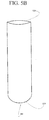
- FIG. 5B shows a vessel comprising a closed end, an open end, and a cylindrical wall formed from the steel plate of FIG. 1 using a plurality of dies;
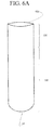
- FIG. 6A shows the vessel of FIG. 5 with a first portion and second portion being defined, wherein the first portion will be progressively narrowed to form a neck;
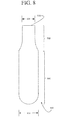
- FIG. 6B is a phase diagram showing the phase structure of the steel used to form Applicant's compressed gas cartridge
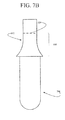
- FIG. 7A shows a first tubular die being used to begin the process of narrowing the first portion of the vessel of FIG. 5B into a tapering neck feature
- FIG. 7B illustrates the tubular die of FIG. 7A being used to form a first neck portion
- FIG. 8 illustrates a first neck portion
- FIG. 9 illustrates a second tubular die being used to further narrow the diameter of the neck portion
- FIG. 10 shows a two stage reduction in the diameter of the neck portion of Applicant's compressed gas cartridge
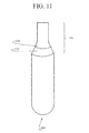
- FIG. 11 shows the two stage reduction of FIG. 10 ;
- FIG. 12 illustrates a nine stage reduction of the neck portion to form an open end having an outer diameter 1220 wherein the body portion comprises an outer diameter 630;
- FIG. 13 shows an enlarged view of the nine stage neck reduction of FIG. 12 .
- the schematic flow charts included are generally set forth as logical flow chart diagrams. As such, the depicted order and labeled steps are indicative of one embodiment of the presented method. Other steps and methods may be conceived that are equivalent in function, logic, or effect to one or more steps, or portions thereof, of the illustrated method. Additionally, the format and symbols employed are provided to explain the logical steps of the method and are understood not to limit the scope of the method. Although various arrow types and line types may be employed in the flow chart diagrams, they are understood not to limit the scope of the corresponding method. Indeed, some arrows or other connectors may be used to indicate only the logical flow of the method. For instance, an arrow may indicate a waiting or monitoring period of unspecified duration between enumerated steps of the depicted method. Additionally, the order in which a particular method occurs may or may not strictly adhere to the order of the corresponding steps shown.
- Applicant's high pressure gas cartridge described and claimed herein are designed for one-time use only. After the compressed gas disposed therein is discharged, the cartridge is discarded. As a result, it is not cost-efficient to equip such disposable cartridges with pressure regulating devices, or overpressure release valves.
- the disposable cartridges of the instant application must not explosively release the pressurized contents when exposed to elevated temperatures for prolonged periods of time.
- the disposable cartridge of this Application will not fail until in internal burst pressure is reached, where that burst pressure if between about 7000 psi to about 8000 psi.
- the cartridge remains in one piece, i.e. no fragments are released, and the seal is not detached during the rupture.
- the Assignee hereof utilizes a quality assurance test whereunder representative samples of each manufacturing lot of the high pressure gas cartridges described and claimed in herein are immersed in boiling water for 30 minutes. If any of the tested pressurized cartridges explode, that manufacturing lot is not released for sale in commerce.
- disposable cartridges of the instant application are formed from a steel slug 100.
- steel slug 100 comprises sheet metal.
- a first die 210 is forced into slug 100 ( FIG. 1 ) to form intermediate vessel 200.
- FIGs. 3 , 4 , and 5A progressively longer dies 310, 410, and 510, respectively, are forced into intermediate vessels 200, 300, and 400, respectively, to form intermediate vessels 300, 400, and 500, respectively.
- FIGs. 2 , 3 , 4 , and 5A The process shown in FIGs. 2 , 3 , 4 , and 5A , is presented for clarity only, and should not be taken as limiting.
- a total of eight (8) stages, employing a total of 8 dies are utilized to form a test-tube-like vessel 500 from steel slug 100, wherein that intermediate vessel 500 is further utilized to form Applicant's compressed gas cartridge.
- a total of nine (9) stages, employing a total of 9 dies are utilized to form a test-tube-like vessel 500 from steel slug 100, wherein that intermediate vessel 500 is further utilized to form Applicant's compressed gas cartridge.
- a total of ten (10) stages employing a total of 10 dies, are utilized to form a test-tube-like vessel 500 from steel slug 100, wherein that intermediate vessel 500 is further utilized to form Applicant's compressed gas cartridge.
- the number of stages used to form vessel 500 from slug 100 is determined by the hardness of the steel comprising slug 100. In certain embodiments, the number of stages used to form vessel 500 from slug 100 is determined by the ambient temperature.
- intermediate vessel 500 comprises a tubular structure having an open end 520 and a closed end 525.
- Portion 530 of vessel 500 extends downwardly from open end 520, and will be formed in a tapering neck structure.
- Portion 540 of vessel 500 extends from the distal end of portion 530 to the bottom of vessel 500, and will comprise the body of Applicant's compressed gas cartridge.
- portion 530 Prior to forming portion 530 into a tapering neck structure, that portion 530 is heated to a temperature of about 700 °C.
- the annealing temperature and the annealing time are adjusted based upon ambient temperature.
- Applicant uses process annealing to treat vessel 500 prior to forming a tapering neck in portion 530. This allows portion 530 to be soft enough to undergo cold working without fracturing.
- This A 1 temperature is about 727 °C (1341 °F), and therefore Applicant heats portion 530 to about 700 °C (1292 °F).
- This process annealing temperature is held long enough to allow recrystallization of the ferrite phase, and then cooled in still air. Since the material stays in the same phase through out the process, the only change that occurs is the size, shape and distribution of the grain structure.
- intermediate vessel 500 comprises an outer diameter 630.
- a first stage diameter reduction process utilizes tubular die 610.
- Tubular die 610 comprises a first end 630 having a first interior diameter 625, a second end 640 having a second interior diameter 620, wherein interior diameter 620 is less than both interior diameter 625 and outer diameter 630, and a truncated cone section comprising a radius of curvature R1 transitioning from the first interior diameter 625 to the second interior diameter 620.
- new vessel 800 comprises a body portion 540 having an outer diameter 630 wherein a portion of neck comprises an outer diameter 620.
- a second stage diameter reduction process utilizes a second tubular die 910.
- top end 520 of vessel 800 is inserted into tubular die 910 having an interior diameter 920, thereby reducing the outer diameter of a portion of neck 530 to the interior diameter 920, wherein interior diameter 920 is less than interior diameter 620.
- Tubular die 910 comprises a second radius of curvature.
- the second radius of curvature of tubular die 910 is less than the first radius of curvature of tubular die 610.
- the second radius of curvature of tubular die 910 is greater than the first radius of curvature of tubular die 610.
- the second radius of curvature of tubular die 910 is substantially equal to the first radius of curvature of tubular die 610.
- new vessel 1000 comprises a body portion 540 having an outer diameter 630 and a neck portion 530 having an outer diameter 920.
- a portion of neck 530 has undergone a two stage reduction in the outside diameter.
- the second stage diameter reduction, performed using tubular die 910 comprising a second radius of curvature, formed portion 1120 are greatly enlarged for clarity.
- Compressed gas cartridge 1200 comprises a length 1210, a neck outer diameter 1220, and a body outer diameter 630.
- length 1210 is about 100 mm
- neck outer diameter 1220 is about 8.7 mm
- body outer diameter is about 21.4 mm.
- length 1210 is about 100 mm
- neck outer diameter 1220 is about 8.3 mm
- body outer diameter is about 21.4 mm.
- length 1210 is about 100 mm
- neck outer diameter 1220 is about 7.6 mm
- body outer diameter is about 25.4 mm.
- FIG. 13 shows neck portion 530 of Applicant's compressed gas cartridge 1200 formed using Applicant's nine stage diameter reduction process.
- a first stage diameter reduction process was performed using a first tubular die comprising a first radius of curvature to form neck portion 1310.
- a second stage diameter reduction process was performed using a second tubular die comprising a second radius of curvature to form neck portion 1320.
- a third stage diameter reduction process was performed using a third tubular die comprising a third radius of curvature to form neck portion 1330.
- a fourth stage diameter reduction process was performed using a fourth tubular die comprising a fourth radius of curvature to form neck portion 1340.
- a fifth stage diameter reduction process was performed using a fifth tubular die comprising a fifth radius of curvature to form neck portion 1350.
- a sixth stage diameter reduction process was performed using a sixth tubular die comprising a sixth radius of curvature to form neck portion 1360.
- a seventh stage diameter reduction process was performed using a seventh tubular die comprising a seventh radius of curvature to form neck portion 1370.
- An eighth stage diameter reduction process was performed using an eighth tubular die comprising an eighth radius of curvature to form neck portion 1380.
- a ninth stage diameter reduction process was performed using a ninth tubular die comprising a ninth radius of curvature to form neck portion 1390.
- neck portions 1360, and/or 1370, and/or 1380, and/or 1390 can compromise the structural integrity of compressed gas cartridge 1200 when filled with a compressed gas.
- the sixth radius of curvature, and/or the seventh radius of curvature, and/or the eighth radius of curvature, and/or the ninth radius of curvature are less than any of the first radius of curvature, the second radius of curvature, the third radius of curvature, the fourth radius of curvature, and the fifth radius of curvature.
- compressed gas cartridge 1200 is filled with liquid carbon dioxide.
- Compressed gas cartridge 1200 comprises an interior volume.
- compressed gas cartridge 1200 is filled with an amount of liquid carbon dioxide equal to about 0.70 times the interior volume.
- compressed gas cartridge 1200 is filled with an amount of liquid carbon dioxide equal to about 0.75 times the interior volume.
- compressed gas cartridge 1200 is filled with an amount of liquid carbon dioxide equal to about 0.80 times the interior volume.
- the filled compressed gas cartridge 1200 After being filled with liquid carbon dioxide, the filled compressed gas cartridge 1200 is sealed.
- a plug-type seal is employed wherein that seal plugs the inner aperture but does not extend outwardly therefrom.
- an overcap seal is employed, wherein that seal comprises a cap that covers the entire end of compressed gas cartridge 1200.
- the number of sequentially progressively longer dies may be 8, 9 or 10.
- the number of sequentially tubular dies may be 8, 9 or 10.
Landscapes
- Engineering & Computer Science (AREA)
- Mechanical Engineering (AREA)
- Ceramic Engineering (AREA)
- Filling Or Discharging Of Gas Storage Vessels (AREA)
- Heat Treatment Of Articles (AREA)
Abstract
Description
- The invention is directed to a compressed gas cartridge and a method to form same.
- Disposable compressed gas cartridges are used in many devices, including bicycle tire inflators, beverage dispensers, and paint ball recreational devices. Prior art methods to form such disposable compressed gas cartridges limit the ratio of body diameters to neck diameters that are available. What is needed is a method to make compressed gas cartridges that facilitates the manufacture of compressed gas cartridges having relatively large cartridge body diameters in combination with relatively small cartridge neck diameters
- A method to form a disposable compressed gas cartridge is presented. The method provides a steel sheet, and using sequentially (N) progressively longer dies forms from the steel sheet a vessel comprising a cylindrical wall, a closed end, and an open end, wherein the cylindrical wall comprises a body diameter, and wherein (N) is greater than equal to 5.
- The method then heats a first portion of the vessel at an annealing temperature, wherein that first portion includes the open end and a portion of the cylindrical wall adjacent the open end. The method then uses sequentially (M) tubular dies to form a cartridge neck by progressively narrowing the first portion of the vessel from the body diameter at a distal end of the first portion to an open end diameter at the open end to form an empty gas cartridge, wherein the body diameter is greater than a neck diameter.
- A compress gas cartridge is presented. The compressed gas cartridge is formed by the method recited hereinabove. Thereafter, the method drills a distal end of the cartridge neck to clear any residual steel from the open end, fills the empty gas cartridge with a compressed gas, and seals the open end.
- The invention will be better understood from a reading of the following detailed description taken in conjunction with the drawings in which like reference designators are used to designate like elements, and in which:
-
FIG.1 , showssteel slug 100 from which the disposable cartridges of the instant application are formed; -
FIG. 2 shows s first die 210 being forced intoslug 100 to formintermediate vessel 200; -
FIGs. 3 ,4 , and5A , show progressively longer dies 310, 410, and 510, respectively, being forced intointermediate vessels -
FIG. 5B shows a vessel comprising a closed end, an open end, and a cylindrical wall formed from the steel plate ofFIG. 1 using a plurality of dies; -
FIG. 6A shows the vessel ofFIG. 5 with a first portion and second portion being defined, wherein the first portion will be progressively narrowed to form a neck; -
FIG. 6B is a phase diagram showing the phase structure of the steel used to form Applicant's compressed gas cartridge; -
FIG. 7A shows a first tubular die being used to begin the process of narrowing the first portion of the vessel ofFIG. 5B into a tapering neck feature; -
FIG. 7B illustrates the tubular die ofFIG. 7A being used to form a first neck portion; -
FIG. 8 illustrates a first neck portion; -
FIG. 9 illustrates a second tubular die being used to further narrow the diameter of the neck portion; -
FIG. 10 shows a two stage reduction in the diameter of the neck portion of Applicant's compressed gas cartridge; -
FIG. 11 shows the two stage reduction ofFIG. 10 ; -
FIG. 12 illustrates a nine stage reduction of the neck portion to form an open end having anouter diameter 1220 wherein the body portion comprises anouter diameter 630; and -
FIG. 13 shows an enlarged view of the nine stage neck reduction ofFIG. 12 . - The invention is described in preferred embodiments in the following description with reference to the Figures, in which like numerals represent the same or similar elements. Reference throughout this specification to "one embodiment," "an embodiment," or similar language means that a particular feature, structure, or characteristic described in connection with the embodiment is included in at least one embodiment of the present invention. Thus, appearances of the phrases "in one embodiment," "in an embodiment," and similar language throughout this specification may, but do not necessarily, all refer to the same embodiment.
- The described features, structures, or characteristics of the invention may be combined in any suitable manner in one or more embodiments. In the following description, numerous specific details are recited to provide a thorough understanding of embodiments of the invention. One skilled in the relevant art will recognize, however, that the invention may be practiced without one or more of the specific details, or with other methods, components, materials, and so forth. In other instances, well-known structures, materials, or operations are not shown or described in detail to avoid obscuring aspects of the invention.
- The schematic flow charts included are generally set forth as logical flow chart diagrams. As such, the depicted order and labeled steps are indicative of one embodiment of the presented method. Other steps and methods may be conceived that are equivalent in function, logic, or effect to one or more steps, or portions thereof, of the illustrated method. Additionally, the format and symbols employed are provided to explain the logical steps of the method and are understood not to limit the scope of the method. Although various arrow types and line types may be employed in the flow chart diagrams, they are understood not to limit the scope of the corresponding method. Indeed, some arrows or other connectors may be used to indicate only the logical flow of the method. For instance, an arrow may indicate a waiting or monitoring period of unspecified duration between enumerated steps of the depicted method. Additionally, the order in which a particular method occurs may or may not strictly adhere to the order of the corresponding steps shown.
- Applicant's high pressure gas cartridge described and claimed herein are designed for one-time use only. After the compressed gas disposed therein is discharged, the cartridge is discarded. As a result, it is not cost-efficient to equip such disposable cartridges with pressure regulating devices, or overpressure release valves.
- However, the disposable cartridges of the instant application must not explosively release the pressurized contents when exposed to elevated temperatures for prolonged periods of time. As a general matter, the disposable cartridge of this Application will not fail until in internal burst pressure is reached, where that burst pressure if between about 7000 psi to about 8000 psi. Again as a general matter, the cartridge remains in one piece, i.e. no fragments are released, and the seal is not detached during the rupture.
- The Assignee hereof utilizes a quality assurance test whereunder representative samples of each manufacturing lot of the high pressure gas cartridges described and claimed in herein are immersed in boiling water for 30 minutes. If any of the tested pressurized cartridges explode, that manufacturing lot is not released for sale in commerce.
- Referring now to
FIG. 1 , disposable cartridges of the instant application are formed from asteel slug 100. In certain embodiments,steel slug 100 comprises sheet metal. Referring now toFIG. 2 , a first die 210 is forced into slug 100 (FIG. 1 ) to formintermediate vessel 200. Referring now toFIGs. 3 ,4 , and5A , progressively longer dies 310, 410, and 510, respectively, are forced intointermediate vessels intermediate vessels - The process shown in
FIGs. 2 ,3 ,4 , and5A , is presented for clarity only, and should not be taken as limiting. In certain embodiments, a total of eight (8) stages, employing a total of 8 dies, are utilized to form a test-tube-like vessel 500 fromsteel slug 100, wherein thatintermediate vessel 500 is further utilized to form Applicant's compressed gas cartridge. In certain embodiments, a total of nine (9) stages, employing a total of 9 dies, are utilized to form a test-tube-like vessel 500 fromsteel slug 100, wherein thatintermediate vessel 500 is further utilized to form Applicant's compressed gas cartridge. In certain embodiments, a total of ten (10) stages, employing a total of 10 dies, are utilized to form a test-tube-like vessel 500 fromsteel slug 100, wherein thatintermediate vessel 500 is further utilized to form Applicant's compressed gas cartridge. - In certain embodiments, the number of stages used to form
vessel 500 fromslug 100 is determined by the hardness of thesteel comprising slug 100. In certain embodiments, the number of stages used to formvessel 500 fromslug 100 is determined by the ambient temperature. - Referring to
FIGs. 5B and6A ,intermediate vessel 500 comprises a tubular structure having anopen end 520 and aclosed end 525.Portion 530 ofvessel 500 extends downwardly fromopen end 520, and will be formed in a tapering neck structure.Portion 540 ofvessel 500 extends from the distal end ofportion 530 to the bottom ofvessel 500, and will comprise the body of Applicant's compressed gas cartridge. - Prior to forming
portion 530 into a tapering neck structure, thatportion 530 is heated to a temperature of about 700 °C. In certain embodiments, the annealing temperature and the annealing time are adjusted based upon ambient temperature. - Applicant uses process annealing to treat
vessel 500 prior to forming a tapering neck inportion 530. This allowsportion 530 to be soft enough to undergo cold working without fracturing. - Referring now to
FIG. 6B , in certain embodiments Applicant heatsportion 530 ofintermediate vessel 500 to a temperature to just below the Ferrite-Austenite region, line A1onFIG. 6B . This A1 temperature is about 727 °C (1341 °F), and therefore Applicant heatsportion 530 to about 700 °C (1292 °F). This process annealing temperature is held long enough to allow recrystallization of the ferrite phase, and then cooled in still air. Since the material stays in the same phase through out the process, the only change that occurs is the size, shape and distribution of the grain structure. - Referring now to
FIG. 7A ,intermediate vessel 500 comprises anouter diameter 630. A first stage diameter reduction process utilizestubular die 610. Tubular die 610 comprises afirst end 630 having a firstinterior diameter 625, asecond end 640 having a secondinterior diameter 620, whereininterior diameter 620 is less than bothinterior diameter 625 andouter diameter 630, and a truncated cone section comprising a radius of curvature R1 transitioning from the firstinterior diameter 625 to the secondinterior diameter 620. - Referring now to
FIG. 7B ,top end 520 ofvessel 500 is inserted into tubular die 610 thereby reducing the outer diameter of a portion ofneck 530 to theinterior diameter 620. Referring now toFIG. 8 ,new vessel 800 comprises abody portion 540 having anouter diameter 630 wherein a portion of neck comprises anouter diameter 620. - A second stage diameter reduction process utilizes a second
tubular die 910. Referring toFIG. 9 ,top end 520 ofvessel 800 is inserted into tubular die 910 having aninterior diameter 920, thereby reducing the outer diameter of a portion ofneck 530 to theinterior diameter 920, whereininterior diameter 920 is less thaninterior diameter 620. Tubular die 910 comprises a second radius of curvature. In certain embodiments, the second radius of curvature of tubular die 910 is less than the first radius of curvature oftubular die 610. In certain embodiments, the second radius of curvature of tubular die 910 is greater than the first radius of curvature oftubular die 610. In certain embodiments, the second radius of curvature of tubular die 910 is substantially equal to the first radius of curvature oftubular die 610. - Referring now to
FIG. 10 ,new vessel 1000 comprises abody portion 540 having anouter diameter 630 and aneck portion 530 having anouter diameter 920. Referring now toFIG. 11 , a portion ofneck 530 has undergone a two stage reduction in the outside diameter. The first stage diameter reduction, performed using tubular die 610 comprising a first radius of curvature, formedportion 1110. The second stage diameter reduction, performed using tubular die 910 comprising a second radius of curvature, formedportion 1120. As those skilled in the art will appreciate, the sizes ofportions - Referring now to
FIG. 12 , in certain embodiments, Applicant uses a nine stage diameter reduction process to formcompressed gas cartridge 1200.Compressed gas cartridge 1200 comprises alength 1210, a neckouter diameter 1220, and a bodyouter diameter 630. In certain embodiments,length 1210 is about 100 mm, neckouter diameter 1220 is about 8.7 mm, and body outer diameter is about 21.4 mm. In certain embodiments,length 1210 is about 100 mm, neckouter diameter 1220 is about 8.3 mm, and body outer diameter is about 21.4 mm. In certain embodiments,length 1210 is about 100 mm, neckouter diameter 1220 is about 7.6 mm, and body outer diameter is about 25.4 mm. -
FIG. 13 showsneck portion 530 of Applicant's compressedgas cartridge 1200 formed using Applicant's nine stage diameter reduction process. A first stage diameter reduction process was performed using a first tubular die comprising a first radius of curvature to formneck portion 1310. A second stage diameter reduction process was performed using a second tubular die comprising a second radius of curvature to formneck portion 1320. A third stage diameter reduction process was performed using a third tubular die comprising a third radius of curvature to formneck portion 1330. A fourth stage diameter reduction process was performed using a fourth tubular die comprising a fourth radius of curvature to formneck portion 1340. - A fifth stage diameter reduction process was performed using a fifth tubular die comprising a fifth radius of curvature to form
neck portion 1350. A sixth stage diameter reduction process was performed using a sixth tubular die comprising a sixth radius of curvature to formneck portion 1360. A seventh stage diameter reduction process was performed using a seventh tubular die comprising a seventh radius of curvature to formneck portion 1370. An eighth stage diameter reduction process was performed using an eighth tubular die comprising an eighth radius of curvature to formneck portion 1380. A ninth stage diameter reduction process was performed using a ninth tubular die comprising a ninth radius of curvature to formneck portion 1390. - Depending on the ratio of
diameter 1220 todiameter 630, thinning can occur inneck portions 1360, and/or 1370, and/or 1380, and/or 1390. Such thinning could compromise the structural integrity ofcompressed gas cartridge 1200 when filled with a compressed gas. - In these embodiments and to reduce thinning in the wall thickness of
neck portions 1360, and/or 1370, and/or 1380, and/or 1390, the sixth radius of curvature, and/or the seventh radius of curvature, and/or the eighth radius of curvature, and/or the ninth radius of curvature, are less than any of the first radius of curvature, the second radius of curvature, the third radius of curvature, the fourth radius of curvature, and the fifth radius of curvature. - In certain embodiments, after forming
compressed gas cartridge 1200 as described herein above, the distal neck portion is drilled to clear any residual steel from the aperture, and cut to assure a flat surface. Thereafter,compressed gas cartridge 1200 is filled with liquid carbon dioxide.Compressed gas cartridge 1200 comprises an interior volume. In certain embodiments,compressed gas cartridge 1200 is filled with an amount of liquid carbon dioxide equal to about 0.70 times the interior volume. In certain embodiments,compressed gas cartridge 1200 is filled with an amount of liquid carbon dioxide equal to about 0.75 times the interior volume. In certain embodiments,compressed gas cartridge 1200 is filled with an amount of liquid carbon dioxide equal to about 0.80 times the interior volume. - After being filled with liquid carbon dioxide, the filled
compressed gas cartridge 1200 is sealed. In certain embodiments, a plug-type seal is employed wherein that seal plugs the inner aperture but does not extend outwardly therefrom. In certain embodiments, an overcap seal is employed, wherein that seal comprises a cap that covers the entire end ofcompressed gas cartridge 1200. - The described features, structures, or characteristics of the invention may be combined in any suitable manner in one or more embodiments. In the above description, numerous specific details are recited to provide a thorough understanding of embodiments of the invention. One skilled in the relevant art will recognize, however, that the invention may be practiced without one or more of the specific details, or with other methods, components, materials, and so forth. In other instances, well-known structures, materials, or operations are not shown or described in detail to avoid obscuring aspects of the invention. In other words, the present invention may be embodied in other specific forms without departing from its spirit or essential characteristics. The described implementations are to be considered in all respects only as illustrative and not restrictive. The scope of the invention should, therefore, be determined not with reference to the above description, but instead should be determined with reference to the pending claims along with their full scope or equivalents, and all changes which come within the meaning and range of equivalency of the claims are to be embraced within their full scope.
- The number of sequentially progressively longer dies may be 8, 9 or 10.
- The number of sequentially tubular dies may be 8, 9 or 10.
Claims (14)
- A method to form a disposable compressed gas cartridge, comprising:providing a steel sheet;using sequentially (N) progressively longer dies to form from said steel sheet a vessel comprising a cylindrical wall, a closed end, and an open end, wherein said cylindrical wall comprises a body diameter, and wherein (N) is greater than equal to 5;heating a first portion of said vessel at an annealing temperature, wherein said first portion includes said open end and a portion of said cylindrical wall adjacent said open end;using sequentially (M) tubular dies to form a cartridge neck by progressively narrowing said first portion of said vessel from said body diameter at a distal end of said first portion to an open end diameter at said open end to form an empty gas cartridge, wherein said body diameter is greater than said neck diameter.
- The method of claim 1, wherein:said steel sheet comprises a Ferrite-Austenite region at temperature of about 727 °C or greater; andsaid annealing temperature is less than 727 °C.
- The method of claim 2, wherein said annealing temperature is about 700 °C.
- The method of any one of the preceding claims, wherein said vessel excluding said first portion is not heated to said annealing temperature.
- The method of any one of the preceding claims, wherein each of said (M) tubular dies comprises a first end having a first interior diameter, a second end having a second interior diameter, and a truncated cone section comprising a radius of curvature transitioning from said first interior diameter to said second interior diameter, wherein said first interior diameter is less than both said second interior diameter and body diameter.
- The method of any one of the preceding claims, further comprising:drilling a distal end of said cartridge neck to clear any residual steel from said open end;filling said empty gas cartridge with a compressed gas; andsealing said open end.
- The method of claim 6, wherein said empty gas cartridge comprises an interior volume, and wherein said filling step comprises filling said empty gas cartridge with an amount of liquid carbon dioxide equal to between about 0.70 times said interior volume and 0.80 times said interior volume.
- The method of any of claims 5 to 7, wherein said length is about 100 mm, said outer body diameter is about 21.4 mm, and said outer neck diameter is about 8.3 mm.
- The method of any of claims 5 to 7, wherein said length is about 100 mm, said outer body diameter is about 25.4 mm, and said outer neck diameter is about 7.6 mm.
- A disposable compressed gas cartridge, formed by a method of:providing a steel sheet;using sequentially (N) progressively longer dies to form from said steel sheet a vessel comprising a cylindrical wall, a closed end, and an open end, wherein said cylindrical wall comprises a body diameter, and wherein (N) is greater than equal to 5;heating a first portion of said vessel at an annealing temperature, wherein said first portion includes said open end and a portion of said cylindrical wall adjacent said open end;using sequentially (M) tubular dies to form a cartridge neck by progressively narrowing said first portion of said vessel from said body diameter at a distal end of said first portion to an open end diameter at said open end to form an empty gas cartridge, wherein said body diameter is greater than said neck diameter.
- The disposable compressed gas cartridge of claim 10, wherein:said steel sheet comprises a Ferrite-Austenite region at temperature of about 727 °C or greater; andsaid annealing temperature is less than 727 °C.
- The disposable compressed gas cartridge of claim 10 or claim 11, wherein each of said (M) tubular dies comprises a first end having a first interior diameter, a second end having a second interior diameter, and a truncated cone section comprising a radius of curvature transitioning from said first interior diameter to said second interior diameter, wherein said first interior diameter is less than both said second interior diameter and body diameter.
- The disposable compressed gas cartridge of any of claims 10 to 12, further comprising:drilling a distal end of said cartridge neck to clear any residual steel from said open end;filling said empty gas cartridge with a compressed gas; andsealing said open end.
- The disposable compressed gas cartridge of claim 13, wherein said empty gas cartridge comprises an interior volume, and wherein said filling step comprises filling said empty gas cartridge with an amount of liquid carbon dioxide equal to between about 0.70 times said interior volume and 0.80 times said interior volume.
Applications Claiming Priority (1)
| Application Number | Priority Date | Filing Date | Title |
|---|---|---|---|
| US13/624,734 US9375772B2 (en) | 2012-09-21 | 2012-09-21 | Compressed gas cartridge and method for making same |
Publications (3)
| Publication Number | Publication Date |
|---|---|
| EP2711105A2 true EP2711105A2 (en) | 2014-03-26 |
| EP2711105A3 EP2711105A3 (en) | 2015-04-29 |
| EP2711105B1 EP2711105B1 (en) | 2018-03-28 |
Family
ID=49301265
Family Applications (1)
| Application Number | Title | Priority Date | Filing Date |
|---|---|---|---|
| EP13185267.5A Not-in-force EP2711105B1 (en) | 2012-09-21 | 2013-09-20 | Method for making a compressed gas cartridge |
Country Status (2)
| Country | Link |
|---|---|
| US (1) | US9375772B2 (en) |
| EP (1) | EP2711105B1 (en) |
Cited By (1)
| Publication number | Priority date | Publication date | Assignee | Title |
|---|---|---|---|---|
| CN104722634A (en) * | 2015-03-24 | 2015-06-24 | 张家港市通润机械有限公司 | Manufacturing process of stainless steel container without weld joint |
Families Citing this family (2)
| Publication number | Priority date | Publication date | Assignee | Title |
|---|---|---|---|---|
| JP6676949B2 (en) * | 2015-12-15 | 2020-04-08 | 東洋製罐グループホールディングス株式会社 | Manufacturing method of metal container |
| CN111360168B (en) * | 2020-02-20 | 2022-02-08 | 上海航天精密机械研究所 | Hydraulic progressive necking device with multiple communicating parts and rubber bag |
Family Cites Families (10)
| Publication number | Priority date | Publication date | Assignee | Title |
|---|---|---|---|---|
| US1059212A (en) * | 1912-01-09 | 1913-04-15 | Charles Henry Augustus Frederick Lockhart Ross | Process of making metal-clad bullets. |
| US2384810A (en) * | 1940-05-13 | 1945-09-18 | Crown Cork & Seal Co | Container |
| US3022567A (en) * | 1955-04-26 | 1962-02-27 | Lyon Inc | Method of making shells |
| DE1933483A1 (en) * | 1968-07-12 | 1970-02-05 | Press Und Stanzwerk Ag | Process for the manufacture of cartridge cases |
| US4493201A (en) * | 1983-01-21 | 1985-01-15 | Alco Industries, Inc. | Method of making a metal bottle for exotic gases under pressure |
| US4753364A (en) * | 1983-03-28 | 1988-06-28 | Stoffel Technologies Inc. | Necked container |
| GB8327016D0 (en) * | 1983-10-10 | 1983-11-09 | Sodastream Ltd | Manufacture of metal containers |
| JPH0771700B2 (en) * | 1988-02-23 | 1995-08-02 | 東洋製罐株式会社 | Redrawing method |
| JP4692147B2 (en) | 2005-08-12 | 2011-06-01 | Jfeスチール株式会社 | Two-piece can manufacturing method and two-piece laminated can |
| EP1882535B1 (en) | 2006-07-26 | 2010-05-05 | Impress Group B.V. | Method and apparatus for forming a steel pressure container, such steel pressure container and a preform therefor |
-
2012
- 2012-09-21 US US13/624,734 patent/US9375772B2/en active Active
-
2013
- 2013-09-20 EP EP13185267.5A patent/EP2711105B1/en not_active Not-in-force
Non-Patent Citations (1)
| Title |
|---|
| None |
Cited By (1)
| Publication number | Priority date | Publication date | Assignee | Title |
|---|---|---|---|---|
| CN104722634A (en) * | 2015-03-24 | 2015-06-24 | 张家港市通润机械有限公司 | Manufacturing process of stainless steel container without weld joint |
Also Published As
| Publication number | Publication date |
|---|---|
| US20140083874A1 (en) | 2014-03-27 |
| EP2711105B1 (en) | 2018-03-28 |
| US9375772B2 (en) | 2016-06-28 |
| EP2711105A3 (en) | 2015-04-29 |
Similar Documents
| Publication | Publication Date | Title |
|---|---|---|
| US9969543B2 (en) | Plastic aerosol container | |
| US9375772B2 (en) | Compressed gas cartridge and method for making same | |
| CN107148386B (en) | Cover kit with internal seal | |
| EP3073067B1 (en) | Method for manufacturing hollow poppet valve | |
| DE102009014057A1 (en) | Pressure vessel for storing hydrogen gas for driving land-based motor vehicle, has liner made of plastic, and flange cooperating with support ring at wall, where section of outer circumference of flange is conical | |
| CA2644648C (en) | Method and device for producing a container | |
| EP2728240A1 (en) | High-pressure gas container and production method for high-pressure gas container | |
| JP4680976B2 (en) | Bottle can body and bottle | |
| CN104039657A (en) | Machine independent metal safety bottle | |
| US20200300413A1 (en) | Bulk metallic glass pressure vessels | |
| JP6604176B2 (en) | Double pipe | |
| CN104792605B (en) | A kind of PTFE Auteclave tank | |
| US20220219880A1 (en) | Beverage container | |
| CN205675461U (en) | Bottle cap structure | |
| JP5028182B2 (en) | How to handle liquid methionine | |
| CN111531058A (en) | A simple pressure vessel manufacturing method based on deep drawing | |
| RU2429930C1 (en) | Manufacturing method of gun liner and gun liner made from aluminium alloy | |
| CN104865117B (en) | A kind of self-recovering type high-pressure digestion composite can of zero consumptive material | |
| CN205203697U (en) | Withstand voltage type 38mm beverage bottle lid | |
| CN205036916U (en) | A check valve case for draught beer freshness retaining barrel | |
| CN218199928U (en) | Twist-off type extraction tube | |
| JP7742992B1 (en) | Capsule for generating hydrogen-containing liquid | |
| US20060260710A1 (en) | Gas capsules and method of filling them | |
| CN201475633U (en) | Sealing structure of high-pressure gas cylinder | |
| CN203258371U (en) | A process manhole structure for cryogenic pressure vessel |
Legal Events
| Date | Code | Title | Description |
|---|---|---|---|
| PUAI | Public reference made under article 153(3) epc to a published international application that has entered the european phase |
Free format text: ORIGINAL CODE: 0009012 |
|
| AK | Designated contracting states |
Kind code of ref document: A2 Designated state(s): AL AT BE BG CH CY CZ DE DK EE ES FI FR GB GR HR HU IE IS IT LI LT LU LV MC MK MT NL NO PL PT RO RS SE SI SK SM TR |
|
| AX | Request for extension of the european patent |
Extension state: BA ME |
|
| RAP1 | Party data changed (applicant data changed or rights of an application transferred) |
Owner name: ILLINOIS TOOL WORKS INC. |
|
| PUAL | Search report despatched |
Free format text: ORIGINAL CODE: 0009013 |
|
| AK | Designated contracting states |
Kind code of ref document: A3 Designated state(s): AL AT BE BG CH CY CZ DE DK EE ES FI FR GB GR HR HU IE IS IT LI LT LU LV MC MK MT NL NO PL PT RO RS SE SI SK SM TR |
|
| AX | Request for extension of the european patent |
Extension state: BA ME |
|
| RIC1 | Information provided on ipc code assigned before grant |
Ipc: B21D 51/24 20060101AFI20150324BHEP Ipc: B21D 51/26 20060101ALI20150324BHEP Ipc: B21D 37/16 20060101ALI20150324BHEP Ipc: B21D 22/28 20060101ALI20150324BHEP Ipc: B21D 41/04 20060101ALI20150324BHEP |
|
| 17P | Request for examination filed |
Effective date: 20151028 |
|
| RBV | Designated contracting states (corrected) |
Designated state(s): AL AT BE BG CH CY CZ DE DK EE ES FI FR GB GR HR HU IE IS IT LI LT LU LV MC MK MT NL NO PL PT RO RS SE SI SK SM TR |
|
| 17Q | First examination report despatched |
Effective date: 20160523 |
|
| GRAP | Despatch of communication of intention to grant a patent |
Free format text: ORIGINAL CODE: EPIDOSNIGR1 |
|
| INTG | Intention to grant announced |
Effective date: 20171017 |
|
| GRAS | Grant fee paid |
Free format text: ORIGINAL CODE: EPIDOSNIGR3 |
|
| GRAA | (expected) grant |
Free format text: ORIGINAL CODE: 0009210 |
|
| AK | Designated contracting states |
Kind code of ref document: B1 Designated state(s): AL AT BE BG CH CY CZ DE DK EE ES FI FR GB GR HR HU IE IS IT LI LT LU LV MC MK MT NL NO PL PT RO RS SE SI SK SM TR |
|
| REG | Reference to a national code |
Ref country code: GB Ref legal event code: FG4D |
|
| RIN1 | Information on inventor provided before grant (corrected) |
Inventor name: CHEN, RAYLIN |
|
| REG | Reference to a national code |
Ref country code: CH Ref legal event code: EP |
|
| REG | Reference to a national code |
Ref country code: AT Ref legal event code: REF Ref document number: 982948 Country of ref document: AT Kind code of ref document: T Effective date: 20180415 |
|
| REG | Reference to a national code |
Ref country code: IE Ref legal event code: FG4D |
|
| REG | Reference to a national code |
Ref country code: DE Ref legal event code: R096 Ref document number: 602013034994 Country of ref document: DE |
|
| PG25 | Lapsed in a contracting state [announced via postgrant information from national office to epo] |
Ref country code: LT Free format text: LAPSE BECAUSE OF FAILURE TO SUBMIT A TRANSLATION OF THE DESCRIPTION OR TO PAY THE FEE WITHIN THE PRESCRIBED TIME-LIMIT Effective date: 20180328 Ref country code: HR Free format text: LAPSE BECAUSE OF FAILURE TO SUBMIT A TRANSLATION OF THE DESCRIPTION OR TO PAY THE FEE WITHIN THE PRESCRIBED TIME-LIMIT Effective date: 20180328 Ref country code: NO Free format text: LAPSE BECAUSE OF FAILURE TO SUBMIT A TRANSLATION OF THE DESCRIPTION OR TO PAY THE FEE WITHIN THE PRESCRIBED TIME-LIMIT Effective date: 20180628 Ref country code: FI Free format text: LAPSE BECAUSE OF FAILURE TO SUBMIT A TRANSLATION OF THE DESCRIPTION OR TO PAY THE FEE WITHIN THE PRESCRIBED TIME-LIMIT Effective date: 20180328 |
|
| REG | Reference to a national code |
Ref country code: NL Ref legal event code: MP Effective date: 20180328 |
|
| REG | Reference to a national code |
Ref country code: LT Ref legal event code: MG4D |
|
| PG25 | Lapsed in a contracting state [announced via postgrant information from national office to epo] |
Ref country code: GR Free format text: LAPSE BECAUSE OF FAILURE TO SUBMIT A TRANSLATION OF THE DESCRIPTION OR TO PAY THE FEE WITHIN THE PRESCRIBED TIME-LIMIT Effective date: 20180629 Ref country code: SE Free format text: LAPSE BECAUSE OF FAILURE TO SUBMIT A TRANSLATION OF THE DESCRIPTION OR TO PAY THE FEE WITHIN THE PRESCRIBED TIME-LIMIT Effective date: 20180328 Ref country code: LV Free format text: LAPSE BECAUSE OF FAILURE TO SUBMIT A TRANSLATION OF THE DESCRIPTION OR TO PAY THE FEE WITHIN THE PRESCRIBED TIME-LIMIT Effective date: 20180328 Ref country code: BG Free format text: LAPSE BECAUSE OF FAILURE TO SUBMIT A TRANSLATION OF THE DESCRIPTION OR TO PAY THE FEE WITHIN THE PRESCRIBED TIME-LIMIT Effective date: 20180628 Ref country code: RS Free format text: LAPSE BECAUSE OF FAILURE TO SUBMIT A TRANSLATION OF THE DESCRIPTION OR TO PAY THE FEE WITHIN THE PRESCRIBED TIME-LIMIT Effective date: 20180328 |
|
| PG25 | Lapsed in a contracting state [announced via postgrant information from national office to epo] |
Ref country code: EE Free format text: LAPSE BECAUSE OF FAILURE TO SUBMIT A TRANSLATION OF THE DESCRIPTION OR TO PAY THE FEE WITHIN THE PRESCRIBED TIME-LIMIT Effective date: 20180328 Ref country code: PL Free format text: LAPSE BECAUSE OF FAILURE TO SUBMIT A TRANSLATION OF THE DESCRIPTION OR TO PAY THE FEE WITHIN THE PRESCRIBED TIME-LIMIT Effective date: 20180328 Ref country code: AL Free format text: LAPSE BECAUSE OF FAILURE TO SUBMIT A TRANSLATION OF THE DESCRIPTION OR TO PAY THE FEE WITHIN THE PRESCRIBED TIME-LIMIT Effective date: 20180328 Ref country code: ES Free format text: LAPSE BECAUSE OF FAILURE TO SUBMIT A TRANSLATION OF THE DESCRIPTION OR TO PAY THE FEE WITHIN THE PRESCRIBED TIME-LIMIT Effective date: 20180328 Ref country code: NL Free format text: LAPSE BECAUSE OF FAILURE TO SUBMIT A TRANSLATION OF THE DESCRIPTION OR TO PAY THE FEE WITHIN THE PRESCRIBED TIME-LIMIT Effective date: 20180328 Ref country code: RO Free format text: LAPSE BECAUSE OF FAILURE TO SUBMIT A TRANSLATION OF THE DESCRIPTION OR TO PAY THE FEE WITHIN THE PRESCRIBED TIME-LIMIT Effective date: 20180328 Ref country code: IT Free format text: LAPSE BECAUSE OF FAILURE TO SUBMIT A TRANSLATION OF THE DESCRIPTION OR TO PAY THE FEE WITHIN THE PRESCRIBED TIME-LIMIT Effective date: 20180328 |
|
| PG25 | Lapsed in a contracting state [announced via postgrant information from national office to epo] |
Ref country code: CZ Free format text: LAPSE BECAUSE OF FAILURE TO SUBMIT A TRANSLATION OF THE DESCRIPTION OR TO PAY THE FEE WITHIN THE PRESCRIBED TIME-LIMIT Effective date: 20180328 Ref country code: SM Free format text: LAPSE BECAUSE OF FAILURE TO SUBMIT A TRANSLATION OF THE DESCRIPTION OR TO PAY THE FEE WITHIN THE PRESCRIBED TIME-LIMIT Effective date: 20180328 Ref country code: SK Free format text: LAPSE BECAUSE OF FAILURE TO SUBMIT A TRANSLATION OF THE DESCRIPTION OR TO PAY THE FEE WITHIN THE PRESCRIBED TIME-LIMIT Effective date: 20180328 |
|
| REG | Reference to a national code |
Ref country code: AT Ref legal event code: MK05 Ref document number: 982948 Country of ref document: AT Kind code of ref document: T Effective date: 20180328 |
|
| PG25 | Lapsed in a contracting state [announced via postgrant information from national office to epo] |
Ref country code: PT Free format text: LAPSE BECAUSE OF FAILURE TO SUBMIT A TRANSLATION OF THE DESCRIPTION OR TO PAY THE FEE WITHIN THE PRESCRIBED TIME-LIMIT Effective date: 20180730 |
|
| REG | Reference to a national code |
Ref country code: DE Ref legal event code: R097 Ref document number: 602013034994 Country of ref document: DE |
|
| PG25 | Lapsed in a contracting state [announced via postgrant information from national office to epo] |
Ref country code: DK Free format text: LAPSE BECAUSE OF FAILURE TO SUBMIT A TRANSLATION OF THE DESCRIPTION OR TO PAY THE FEE WITHIN THE PRESCRIBED TIME-LIMIT Effective date: 20180328 Ref country code: AT Free format text: LAPSE BECAUSE OF FAILURE TO SUBMIT A TRANSLATION OF THE DESCRIPTION OR TO PAY THE FEE WITHIN THE PRESCRIBED TIME-LIMIT Effective date: 20180328 |
|
| PLBE | No opposition filed within time limit |
Free format text: ORIGINAL CODE: 0009261 |
|
| STAA | Information on the status of an ep patent application or granted ep patent |
Free format text: STATUS: NO OPPOSITION FILED WITHIN TIME LIMIT |
|
| 26N | No opposition filed |
Effective date: 20190103 |
|
| REG | Reference to a national code |
Ref country code: DE Ref legal event code: R119 Ref document number: 602013034994 Country of ref document: DE |
|
| PG25 | Lapsed in a contracting state [announced via postgrant information from national office to epo] |
Ref country code: MC Free format text: LAPSE BECAUSE OF FAILURE TO SUBMIT A TRANSLATION OF THE DESCRIPTION OR TO PAY THE FEE WITHIN THE PRESCRIBED TIME-LIMIT Effective date: 20180328 |
|
| REG | Reference to a national code |
Ref country code: CH Ref legal event code: PL |
|
| GBPC | Gb: european patent ceased through non-payment of renewal fee |
Effective date: 20180920 |
|
| PG25 | Lapsed in a contracting state [announced via postgrant information from national office to epo] |
Ref country code: SI Free format text: LAPSE BECAUSE OF FAILURE TO SUBMIT A TRANSLATION OF THE DESCRIPTION OR TO PAY THE FEE WITHIN THE PRESCRIBED TIME-LIMIT Effective date: 20180328 |
|
| REG | Reference to a national code |
Ref country code: BE Ref legal event code: MM Effective date: 20180930 |
|
| REG | Reference to a national code |
Ref country code: IE Ref legal event code: MM4A |
|
| PG25 | Lapsed in a contracting state [announced via postgrant information from national office to epo] |
Ref country code: LU Free format text: LAPSE BECAUSE OF NON-PAYMENT OF DUE FEES Effective date: 20180920 |
|
| PG25 | Lapsed in a contracting state [announced via postgrant information from national office to epo] |
Ref country code: IE Free format text: LAPSE BECAUSE OF NON-PAYMENT OF DUE FEES Effective date: 20180920 Ref country code: DE Free format text: LAPSE BECAUSE OF NON-PAYMENT OF DUE FEES Effective date: 20190402 |
|
| PG25 | Lapsed in a contracting state [announced via postgrant information from national office to epo] |
Ref country code: BE Free format text: LAPSE BECAUSE OF NON-PAYMENT OF DUE FEES Effective date: 20180930 Ref country code: FR Free format text: LAPSE BECAUSE OF NON-PAYMENT OF DUE FEES Effective date: 20180930 Ref country code: LI Free format text: LAPSE BECAUSE OF NON-PAYMENT OF DUE FEES Effective date: 20180930 Ref country code: CH Free format text: LAPSE BECAUSE OF NON-PAYMENT OF DUE FEES Effective date: 20180930 |
|
| PG25 | Lapsed in a contracting state [announced via postgrant information from national office to epo] |
Ref country code: GB Free format text: LAPSE BECAUSE OF NON-PAYMENT OF DUE FEES Effective date: 20180920 |
|
| PG25 | Lapsed in a contracting state [announced via postgrant information from national office to epo] |
Ref country code: MT Free format text: LAPSE BECAUSE OF NON-PAYMENT OF DUE FEES Effective date: 20180920 |
|
| PG25 | Lapsed in a contracting state [announced via postgrant information from national office to epo] |
Ref country code: TR Free format text: LAPSE BECAUSE OF FAILURE TO SUBMIT A TRANSLATION OF THE DESCRIPTION OR TO PAY THE FEE WITHIN THE PRESCRIBED TIME-LIMIT Effective date: 20180328 |
|
| PG25 | Lapsed in a contracting state [announced via postgrant information from national office to epo] |
Ref country code: HU Free format text: LAPSE BECAUSE OF FAILURE TO SUBMIT A TRANSLATION OF THE DESCRIPTION OR TO PAY THE FEE WITHIN THE PRESCRIBED TIME-LIMIT; INVALID AB INITIO Effective date: 20130920 |
|
| PG25 | Lapsed in a contracting state [announced via postgrant information from national office to epo] |
Ref country code: CY Free format text: LAPSE BECAUSE OF FAILURE TO SUBMIT A TRANSLATION OF THE DESCRIPTION OR TO PAY THE FEE WITHIN THE PRESCRIBED TIME-LIMIT Effective date: 20180328 Ref country code: MK Free format text: LAPSE BECAUSE OF NON-PAYMENT OF DUE FEES Effective date: 20180328 |
|
| PG25 | Lapsed in a contracting state [announced via postgrant information from national office to epo] |
Ref country code: IS Free format text: LAPSE BECAUSE OF FAILURE TO SUBMIT A TRANSLATION OF THE DESCRIPTION OR TO PAY THE FEE WITHIN THE PRESCRIBED TIME-LIMIT Effective date: 20180728 |