EP2710973A1 - Koagulationselektrode - Google Patents
Koagulationselektrode Download PDFInfo
- Publication number
- EP2710973A1 EP2710973A1 EP13191846.8A EP13191846A EP2710973A1 EP 2710973 A1 EP2710973 A1 EP 2710973A1 EP 13191846 A EP13191846 A EP 13191846A EP 2710973 A1 EP2710973 A1 EP 2710973A1
- Authority
- EP
- European Patent Office
- Prior art keywords
- sleeve
- lamellae
- slats
- iris diaphragm
- ring
- Prior art date
- Legal status (The legal status is an assumption and is not a legal conclusion. Google has not performed a legal analysis and makes no representation as to the accuracy of the status listed.)
- Granted
Links
- 238000005345 coagulation Methods 0.000 title claims description 21
- 230000015271 coagulation Effects 0.000 title claims description 21
- 210000000056 organ Anatomy 0.000 abstract description 53
- 241000446313 Lamella Species 0.000 abstract description 8
- 241000790351 Iris latifolia Species 0.000 abstract 1
- 230000003872 anastomosis Effects 0.000 description 11
- 238000000034 method Methods 0.000 description 10
- 230000008569 process Effects 0.000 description 6
- 239000004020 conductor Substances 0.000 description 5
- 210000004204 blood vessel Anatomy 0.000 description 4
- 210000000078 claw Anatomy 0.000 description 3
- 238000003466 welding Methods 0.000 description 3
- 208000027418 Wounds and injury Diseases 0.000 description 2
- 239000000853 adhesive Substances 0.000 description 2
- 230000001070 adhesive effect Effects 0.000 description 2
- 230000015572 biosynthetic process Effects 0.000 description 2
- 230000008878 coupling Effects 0.000 description 2
- 238000010168 coupling process Methods 0.000 description 2
- 238000005859 coupling reaction Methods 0.000 description 2
- 230000006378 damage Effects 0.000 description 2
- 208000014674 injury Diseases 0.000 description 2
- 230000007246 mechanism Effects 0.000 description 2
- 102000009123 Fibrin Human genes 0.000 description 1
- 108010073385 Fibrin Proteins 0.000 description 1
- BWGVNKXGVNDBDI-UHFFFAOYSA-N Fibrin monomer Chemical compound CNC(=O)CNC(=O)CN BWGVNKXGVNDBDI-UHFFFAOYSA-N 0.000 description 1
- 241000209035 Ilex Species 0.000 description 1
- 208000007536 Thrombosis Diseases 0.000 description 1
- 210000003484 anatomy Anatomy 0.000 description 1
- 238000013459 approach Methods 0.000 description 1
- 210000001367 artery Anatomy 0.000 description 1
- 230000000712 assembly Effects 0.000 description 1
- 238000000429 assembly Methods 0.000 description 1
- 238000006243 chemical reaction Methods 0.000 description 1
- 150000001875 compounds Chemical class 0.000 description 1
- 229950003499 fibrin Drugs 0.000 description 1
- 238000004519 manufacturing process Methods 0.000 description 1
- 238000010297 mechanical methods and process Methods 0.000 description 1
- 230000005226 mechanical processes and functions Effects 0.000 description 1
- 239000000615 nonconductor Substances 0.000 description 1
- 150000002894 organic compounds Chemical class 0.000 description 1
- 238000002360 preparation method Methods 0.000 description 1
- 238000003825 pressing Methods 0.000 description 1
- 102000004169 proteins and genes Human genes 0.000 description 1
- 108090000623 proteins and genes Proteins 0.000 description 1
- 239000000565 sealant Substances 0.000 description 1
- 230000007480 spreading Effects 0.000 description 1
- 238000003892 spreading Methods 0.000 description 1
- 239000000126 substance Substances 0.000 description 1
- 238000001356 surgical procedure Methods 0.000 description 1
- 230000002459 sustained effect Effects 0.000 description 1
- 230000002885 thrombogenetic effect Effects 0.000 description 1
- 230000002588 toxic effect Effects 0.000 description 1
- 231100000563 toxic property Toxicity 0.000 description 1
- 238000002054 transplantation Methods 0.000 description 1
- 210000003462 vein Anatomy 0.000 description 1
Images






Classifications
-
- A—HUMAN NECESSITIES
- A61—MEDICAL OR VETERINARY SCIENCE; HYGIENE
- A61B—DIAGNOSIS; SURGERY; IDENTIFICATION
- A61B17/00—Surgical instruments, devices or methods
- A61B17/11—Surgical instruments, devices or methods for performing anastomosis; Buttons for anastomosis
-
- A—HUMAN NECESSITIES
- A61—MEDICAL OR VETERINARY SCIENCE; HYGIENE
- A61B—DIAGNOSIS; SURGERY; IDENTIFICATION
- A61B18/00—Surgical instruments, devices or methods for transferring non-mechanical forms of energy to or from the body
- A61B18/04—Surgical instruments, devices or methods for transferring non-mechanical forms of energy to or from the body by heating
- A61B18/12—Surgical instruments, devices or methods for transferring non-mechanical forms of energy to or from the body by heating by passing a current through the tissue to be heated, e.g. high-frequency current
- A61B18/14—Probes or electrodes therefor
- A61B18/1402—Probes for open surgery
-
- A—HUMAN NECESSITIES
- A61—MEDICAL OR VETERINARY SCIENCE; HYGIENE
- A61B—DIAGNOSIS; SURGERY; IDENTIFICATION
- A61B18/00—Surgical instruments, devices or methods for transferring non-mechanical forms of energy to or from the body
- A61B18/04—Surgical instruments, devices or methods for transferring non-mechanical forms of energy to or from the body by heating
- A61B18/12—Surgical instruments, devices or methods for transferring non-mechanical forms of energy to or from the body by heating by passing a current through the tissue to be heated, e.g. high-frequency current
- A61B18/14—Probes or electrodes therefor
- A61B18/1442—Probes having pivoting end effectors, e.g. forceps
-
- A—HUMAN NECESSITIES
- A61—MEDICAL OR VETERINARY SCIENCE; HYGIENE
- A61B—DIAGNOSIS; SURGERY; IDENTIFICATION
- A61B17/00—Surgical instruments, devices or methods
- A61B17/11—Surgical instruments, devices or methods for performing anastomosis; Buttons for anastomosis
- A61B2017/1103—Approximator
-
- A—HUMAN NECESSITIES
- A61—MEDICAL OR VETERINARY SCIENCE; HYGIENE
- A61B—DIAGNOSIS; SURGERY; IDENTIFICATION
- A61B17/00—Surgical instruments, devices or methods
- A61B17/11—Surgical instruments, devices or methods for performing anastomosis; Buttons for anastomosis
- A61B2017/1107—Surgical instruments, devices or methods for performing anastomosis; Buttons for anastomosis for blood vessels
-
- A—HUMAN NECESSITIES
- A61—MEDICAL OR VETERINARY SCIENCE; HYGIENE
- A61B—DIAGNOSIS; SURGERY; IDENTIFICATION
- A61B18/00—Surgical instruments, devices or methods for transferring non-mechanical forms of energy to or from the body
- A61B2018/00053—Mechanical features of the instrument of device
- A61B2018/00184—Moving parts
-
- A—HUMAN NECESSITIES
- A61—MEDICAL OR VETERINARY SCIENCE; HYGIENE
- A61B—DIAGNOSIS; SURGERY; IDENTIFICATION
- A61B18/00—Surgical instruments, devices or methods for transferring non-mechanical forms of energy to or from the body
- A61B2018/00571—Surgical instruments, devices or methods for transferring non-mechanical forms of energy to or from the body for achieving a particular surgical effect
- A61B2018/00589—Coagulation
-
- A—HUMAN NECESSITIES
- A61—MEDICAL OR VETERINARY SCIENCE; HYGIENE
- A61B—DIAGNOSIS; SURGERY; IDENTIFICATION
- A61B18/00—Surgical instruments, devices or methods for transferring non-mechanical forms of energy to or from the body
- A61B2018/00571—Surgical instruments, devices or methods for transferring non-mechanical forms of energy to or from the body for achieving a particular surgical effect
- A61B2018/00619—Welding
Definitions
- the invention relates to a coagulation electrode according to claim 1.
- An anastomosis is a connection between two anatomical structures.
- severed blood vessels may be connected by anastomoses during organ transplantation.
- connection can be made using suture techniques.
- approaches that allow an organic compound by means of adhesive techniques. Frequently fibrin sealants are used, which allow a very advantageous combination of organs, in particular hollow organs.
- fibrin sealants are used, which allow a very advantageous combination of organs, in particular hollow organs.
- compatibility of these adhesives is problematic because they can have thrombogenic and toxic properties.
- Clamping techniques are also used to connect at a suitable location.
- Various aids such as rings, cuffs or stents, are used to assist in performing anastomoses.
- WO 03/061487 A1 It is known to connect hollow organs by the application of a suitable high-frequency current (RF current).
- RF current high-frequency current
- the application of the HF current results in biological welding of the tissue structures.
- the cell substance clots, whereby the protein structures stick together, so that a controlled, safe and fast connection can be established.
- the WO 03/061487 A1 an instrument with an inner sleeve and an outer sleeve ready. These sleeves each include an electrode which is annular and to which the RF current is applied. So it is a bipolar RF instrument.
- the first end is passed through the inner sleeve and folded over so that the tissue comes to rest on the outside of the inner sleeve.
- the second end of the vessel is pulled over the inner sleeve and the end portion of the blood vessel thereon.
- the outer sleeve can be opened and put over the inner sleeve and the tissue located thereon.
- the electrodes are arranged on the sleeves such that the first end and the second end of the vessel are clamped between the electrodes at the sleeves. When the HF current is applied, it flows through the tissue and fuses the ends.
- a problem of WO 03/061487 A1 is that for welding or coagulation of hollow organs with different diameters, a plurality of differently ausgestalteter instruments are needed.
- the gap between electrodes and sleeves must be dimensioned such that it is adapted to the diameter of the wall thicknesses.
- the coagulation process requires a sustained pressing of the tissue structures or vessel end sections throughout the coagulation process.
- a device for producing anastomoses between a first and a second hollow organ which is easy to use and suitable for the formation of high-quality anastomoses and avoids the aforementioned disadvantages. Furthermore, a suitable coagulation electrode should be specified.
- the present invention solves this problem by the coagulation electrode according to claim 1.
- a device for producing anastomoses between a first and a second hollow organ each having an inner and an outer surface comprising a sleeve with an inner electrode assembly, through which the first hollow member is everted so that its inner surface comes to lie outside, and an outer electrode assembly, the inner electrode assembly is in particular radially opposite and with the second hollow member, which is pushed over the first hollow member, in electrical contact can be brought so that the electrode assemblies contact outer surfaces of the hollow organs, wherein the outer electrode assembly a Variety of by at least one guide member against each other movable slats comprises, which are designed and movably arranged such that inner edges of the slats in a closed state form a through hole and abut the second hollow organ and in a ⁇ Stammsz a gap leading from the outside to the passage opening is formed between the lamellae, through which the interconnected hollow organs can be led out of the passage opening to the outside.
- the outer electrode is formed by a plurality of mutually movable blades.
- the fins are arranged so that they can assume at least two states, a closed state and an open state.
- the opening state at least the lamellae are spaced apart from the sleeve with the inner electrode arrangement in such a way that a through opening is formed in which the corresponding sections of the hollow organs can be positioned, preferably still with a substantial absence of tissue contact and radial force.
- the inner edges of the slats are at least partially on the hollow organ and allow direct application of the HF current.
- the outer electrode arrangement with the lamellae is divisible.
- a gap may form, which is the Slats divides. Due to the gap, the unconnected hollow organ or vessel can be introduced or the connected removed from the device. Preferably, the lamellae can exert a mechanical pressure on the hollow organs. The closing and coagulation conditions can be determined relatively accurately. This can ensure the formation of anastomoses with a high load capacity. After a connection of the hollow organs can be easily removed in the open state, the device. Damage to the organs or excessive loading of the compound produced is avoided.
- the lamellae can be adjustable in such a way that, in the closed state, an opening is created which corresponds to the hollow organ to be treated.
- hollow organs can be treated, which have different dimensions.
- blood vessels with different diameters can be treated.
- An instrument may be suitable for connecting veins and arteries.
- the lamellae can be constructed and / or arranged in the manner of an iris diaphragm.
- the passage opening is thus constructed substantially circular. This is advantageous for a large number of applications, for example in the connection of vessels.
- an iris diaphragm is particularly suitable for providing a substantially continuous contact surface of the lamellae.
- An applied mechanical pressure can be regularly distributed over the outer and surface of the second hollow organ.
- the sleeve can be arranged fixed relative to the outer electrode in a holder or a holder.
- the sleeve is in a predetermined position relative to the outer electrode. Positioning the sleeve relative to the outer electrode is thus unnecessary.
- the device according to the invention can be constructed much more compact by the fixation in a holder. The handling is facilitated by the fixed or adjustable positioning.
- the holder may be removable for individual handling of the sleeve. That is, the holder can be detached from the device and operate separately from this.
- the first hollow organ and / or the second hollow organ in or on the sleeve.
- sleeve and device can be coupled so that the sleeve against the Outer electrode is located in an advantageous position.
- the inner edges of the slats may have a substantially equal distance to the sleeve in the closed state. In the closed state, therefore, the inner edges lie on the second hollow organ, in particular on its inner surface.
- the HF current is applied directly to the tissue. The connection achieved is correspondingly higher quality.
- the passage opening can be adjustable in terms of its diameter by moving the slats.
- the device can thus be opened and closed by moving the slats.
- the gap may, in the open state, divide the outer electrode into two halves which are movable away from each other.
- an iris diaphragm which can be divided, for example, in two semicircles. The gentle removal of the device after a coagulation process is thus facilitated.
- the sleeve can be held on an actuating device and designed such that it can be dismantled into two parts such that the parts can also be brought from a closed state to form a closed tubular section into an open state for removal from the hollow organ.
- the sleeve can therefore be designed in two parts, so that it can be disassembled after or before the application of the HF current. For example, it may be possible to spread apart the individual parts of the sleeve to ensure better handling of the organs. The spreading of the sleeve can also prevent the slipping of the hollow organ which has been slipped over the sleeve.
- the actuator may be biased in a closed state.
- the closed state automatically turns on.
- the slats can be biased by a clamping device in the closed state with a defined force.
- the clamping device can be adjusted such that the slats are pressed in the closed state with a predefined force against the hollow organs. Not only does this force allow for secure coagulation of the tissue, it is also sized to be nonexistent Injury of the hollow organs comes. By adjusting the tensioning device, a repeatability of the treatment results can be ensured.
- Such a coagulation electrode has similar advantages to those of the device described above.
- the coagulation electrode is divisible and thus easily removable after the application of the HF current. That is, the coagulation electrode is easily removed from the connected hollow organ.
- the link ring can also be a lamella and take over their functions.
- the slide ring may comprise slide ring sections which are each movable separately from one another, in particular by guide rods.
- the link ring may comprise exactly two link ring sections which form the link ring.
- the sections can be used to operate the slats.
- the lamellae can be rotated by means of the sections opposite the bearing ring (preferably comprising two bearing ring sections). The slats are brought into the opening or closing state.
- Fig. 1 shows an electrosurgical instrument 10 for the production of anastomoses.
- the instrument 10 comprises a base plate 13 on which branches 12, 12 'are rotatably mounted.
- a closure device 20 serves to actuate the branches 12, 12 '.
- This comprises a closure actuating element 24, which is connected via a slotted guide with the branches 12, 12 '.
- the shutter actuator 24 has substantially two positions, a first position in which the electrosurgical instrument 10 is opened and a second position in which the electrosurgical instrument 10 is closed.
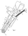
- the closure device 20 is designed such that the branches 12, 12 'are fixed in the second position, so that unintentional opening of the electrosurgical instrument 10 is not possible (cf. Fig. 2 ).
- the electrosurgical instrument 10 has a clamping device 40 for actuating the iris diaphragm 50.
- This tensioner 40 comprises a tensioner actuator 42, a force deflector 44 rotatably mounted on the base plate 13, a tension spring 41, and two actuators 52, 52 '.
- the adjusting elements 52, 52 ' each extend along the first branch 12 or the second branch 12' and transmit the forces exerted by the tensioning device 40 on the mechanics of the iris diaphragm 50.
- the tensioning device 40 is also in the open position of the electrosurgical instrument 10 in an open position (cf. Fig. 1 ). In the second, closed position of the electrosurgical instrument 10, the tensioner 40 can be tensioned by operating the tensioner actuator 42.
- FIG. 3 shows the tensioner actuator 42 in a tensioned condition.
- the tension spring 41 connected to the force deflector 44 is tensioned.
- the rod or the adjusting elements 52, 52 ' which attach substantially point-symmetrically to this pivot point on the force deflector 44, perform a translational movement in proximal (actuator 52') and distal (actuator 52) direction. As further explained below, this movement leads to a closing and opening of the iris diaphragm 50.
- the tension spring 41 in the tensioned state via the adjusting elements 52, 52 ' continuously exerts a force on the mechanism of the iris diaphragm 50.
- the amount of this force can be controlled by a Sch thoroughlykrafteinstellvorraum 45 (see. Fig. 3 ) to adjust.
- the embodiment of the force deflector 44 according to the Fig. 3 For this purpose, a multiplicity of bores, which have different distances from the pivot point of the force deflector 44, are included.
- the tension spring 41 is designed such that it can be anchored in the individual holes. Thus, the spring force of the tension spring 41 depending on the position in the holes with a different lever to the force deflector 44. As in Fig.
- the force deflector 44 projects beyond the base plate 15 so that it is manually operable.
- the iris diaphragm 50 can also be closed and opened in the non-tensioned state via the force deflector 44, which serves as an actuating element.
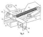
- Fig. 4 shows a further embodiment of the clamping device 40.
- the Schellerkrafteinstellvorraum 45 includes a screw 46 and an angle 47.
- the angle 47 is fixed to the force deflector 44 that this can be moved by operating the screw 46 along a longitudinal axis.
- the tension spring 41 is applied to the angle 47.
- a positioning device 30 (cf. Fig. 5 ). This comprises a sleeve 32 for receiving the hollow organs and two sleeve actuation branches 35, 35 '.
- the positioning device 30 essentially serves to position the hollow organs in the center of the iris diaphragm 50. Furthermore, it provides a sleeve electrode 36.
- the sleeve 32 is substantially cylindrical and comprises a first sleeve portion 33 and a second sleeve portion 33 '. In cross section, transverse to the longitudinal axis of the sleeve 32, the sleeve portions 33, 33 'each form a semicircle.
- the sleeve portions 33, 33 ' are connected to the sleeve actuating industries 35 and 35', respectively. These are rotatably attached to a removable portion 13 'of the base plate 13 that the sleeve portions 33, 33' open and close. In the closed state, the sleeve portions 33, 33 'abut each other and form the sleeve 32. Thus, the positioning device 30 can be opened and closed via the sleeve actuation branches 35, 35'.
- the sleeve actuating industries 35, 35 ' acted upon by a spring force which holds the sleeve sections 35, 35' closed.
- the positioning device 30 can be detached from the other components of the electrosurgical instrument 10 and handled individually.
- the divisibility of the sleeve 32 is particularly advantageous when applying and removing the instrument 10 to the hollow organ.
- the sleeve 32 comprises at least two mandrels 28, which are arranged radially to the longitudinal axis of the sleeve 32 and on the sleeve portions 33, 33 '. If the hollow organ or its sections are pushed over the sleeve 32, then the pins 28 fix the hollow organs or vessels which have been pushed over. Their feed is limited by the sleeve operating industries 35, 35 '.
- the detachable section 13 ' can be reconnected to the base plate 13 and brought into a position suitable for connecting the sections of the hollow organ.
- an essential point of the present invention is to construct the device head of the electrosurgical instrument 10 in the form of a divisible iris diaphragm.
- the iris diaphragm 50 comprises two half-screens 51, 51 ', which cooperate in the closed state as an iris diaphragm 50.
- the structure of a half-stop, namely the half-stop 51 is in the Fig. 6 illustrated.
- This comprises a mounting plate 56, which is formed substantially semicircular and fixed to the first sector 12 is connected.
- a likewise semicircular shell 57 extends.
- the shell 57 has an opening 60 through which a crescent-shaped adjusting disk 54 projects into the interior of the half-aperture 51.
- the adjusting disc 54 can be actuated such that it performs a circular movement about the center of the iris diaphragm 50.
- Claws 59, 59' on the lamellae 53, 53 ', 53" engage in corresponding lamellae lanes 58 in the adjusting disk 54 a.
- the lamellae 53, 53 ', 53 are thus designed and arranged such that the orientation of the lamellae 53, 53', 53" can be changed by the movement of the adjusting disk 54.
- the slats can take at least two positions.
- the fins 53, 53 ', 53 "have inner walls 66 which act as electrodes first position ( Fig. 9 ) are the slats 53, 53 'positioned so that they hardly protrude beyond the adjusting disc 54. It forms a circular passage opening into which the sleeve 32 protrudes. Between the sleeve 32 and the inner edges 66 of the fins 53, 53 'is a gap which is suitable for receiving portions of the hollow organs.
- the passage opening is reduced in size such that the inner edges 66 of the lamellae 53, 53 ', 53 "rest on the sleeve 32 (cf. Fig. 8 ).
- tissue sections of the hollow organs between the inner edges of the fins 53, 53 ', 53 "and the sleeve 32 they are pressed together with a predefined force against each other and against the sleeve 32. This force can be adjusted with the Sch Schweizerkrafteinstellvortechnisch 45 and is on the Control elements 52, 52 'on the fins 53, 53', 53 "transmitted.
- the covers 55, 55a are mutually arranged on the half panels 51, 51 'and protect their mechanics.
- Fig. 7 shows a further embodiment of the fins 53, 53 '. These are designed in a stepped manner and close in such a way that a first louver 53 not only slides up onto the second louver 53 'during the closing process, but also engages in the latter.
- FIG. 10 Another embodiment of the blades 53, 53 'can be the 10 and 11 remove.
- the 10 and 11 show the iris diaphragm 50 according to the invention in plan view, wherein the iris diaphragm 50 in Fig. 10 closed and in Fig. 11 is open.
- the cover 55 ' is in FIG Fig. 10 away. It can be seen that the lamellae 53, 53 'engage via T-armature 59a, 59a' in the slotted guide 58 of the adjusting disk 54.
- Pins which are arranged on the adjusting disc 54 of the half-diaphragms 51, 51 'and project into the covers 55, 55' form a slotted guide for the adjusting discs 54. They guide the adjusting discs 54 in their rotational movement about the center of the iris diaphragm 50 and thereby increase the closing area of the slats.
- the Fig. 12 to 14 show a further embodiment of the mechanism of the iris diaphragm 50 according to the invention with a simpler structure.
- a coordinate system is introduced.
- the X-axis This coordinate system extends substantially along an industry 12.
- the Y-axis is transverse thereto and points to the center of the passage opening of the iris diaphragm 50th
- the Fig. 12 shows by way of example the first half-stop 51 in an exploded view.
- An essential difference of the embodiment according to the Fig. 12 to 14 opposite to the Fig. 6 is that the function of the adjusting disk 54 in the embodiments of the Fig. 12 to 14 by a lamella 53 to 53 ", namely the lamella 53 'is perceived Fig. 12 also firmly connected to the first industry 12. It comprises three recesses 61, 61 ', 61 ", which are opened radially in the direction of the center of the passage opening of the iris diaphragm 50.
- these recesses 61, 61', 61" are mounted lamellae pins 63, 63 ', 63 " Essentially arranged centrally on the fins 53, 53 '53 ".
- the recesses 61, 61 ', 61 form a slotted guide along which the individual slats 53, 53'53” can be moved to the center of the passage opening.
- the louver pins 63, 63 ', 63 are formed on both sides of the louvers 53, 53', 53". They engage on the one side in the recesses 61, 61 ', 61 "of the mounting plate 56 and on the other side of the fins 53, 53', 53” in recesses 65, 65 ', 65 “of the cover 55.
- the recesses 65th , 65 ', 65 "of the covers 55 also extend substantially toward the center of the through hole of the iris diaphragm 50.
- the blade 53 ' is rigidly connected to the actuator 52 and has for this purpose a corresponding extension.
- the actuator 52 is actuated along the Y axis.
- the semicircular louvers 53 to 53 "have at their ends in each case a recess 64, 64 ', 64", 64 “', which engage in the pins 63, 63 ', 63" of the other lamellae 53 to 53 " mechanical coupling between the first blade 53 and the second blade 53 '(recess 64, 64') which in turn is connected to the third blade 53 "(recess 64", 64 "').
- Movement of the second louver 53 'along the Y-axis actuates and displaces the first and third louvers 53, 53 ", and the slide guides are configured to move each of the louvers 53 to 53" toward the center of the through-hole. when the second louver 53 'is shifted along the Y-axis. By a counter-movement of the second blade 53 ', this movement can be reversed.
- the iris diaphragm 50 opens.
- the second half-aperture is correspondingly symmetrical.
- the FIGS. 13 and 14 show the half-panels 51, 51 '. It turns out that the first louver 53 of the first Half shutter 51 in a closed state of the electrosurgical instrument 10, a mechanical connection with its opposite blade 53 "" received. There is also a connection between the lamellar pins 63, 63 ', 63 "and the recesses 64, 64', 64". The same applies to the third slat 53 ".
- the coupling of the lamellae 53 to 53 "of the first half-stop 51 with that of the second half-stop 51 is detachable.
- the iris diaphragm 50 has a gap through which the connected hollow organ can be separated from the instrument 10.
- the closed state of the electrosurgical instrument 10 thus forms a ring of fins 53 to 53 "", which according to the embodiment of Fig. 12 to 14 includes six lamellae.
- the individual lamellae 53-53 '' are in each case in operative connection with the lamellae 53-53 '' adjacent to them.
- a slotted guide is formed which permits a translational movement of the individual slats 53 to 53 '' in the direction of the center of the passage opening, ie the actuation of the adjusting elements 52, 52 'is transmitted mechanically to the individual slats 53 to 53''' ,
- the iris diaphragm 50 comprises a first outer electrode arrangement or outer electrode, the sleeve 32 an inner electrode arrangement, namely the sleeve electrode 36. As in the Fig. 5 As shown, these electrodes are arranged adjacent to each other. The portions of hollow organs which are clamped between the iris diaphragm 50 and the sleeve 32 can be connected to each other by means of these electrodes. For this purpose, a corresponding HF current is applied to the electrodes. The RF current coagulates the tissue sections located between the electrodes. In order to apply the HF current, the electrosurgical instrument 10 has corresponding conductor tracks and connections. For example, the sleeve electrode 36 may be powered via a trace within the sleeve actuating industries 55, 55 '. A corresponding track for the iris can be located within the branches 12, 12 '.
- branches 12, 12 'and / or the sleeve actuation branches 53, 53' may be formed wholly or partly of electrically conductive material in order to provide a corresponding trace.
- the individual lamellae 53 to 53 '" may comprise electrodes for application of the HF current and / or be formed of electrically conductive material.
- the base plate 13 and the detachable portion 13 'of the base plate 13 is an electrical insulator.
- the conductor track of the sleeve electrode 36 is at least electrically insulated from the conductor track of the iris diaphragm 50.
- the base plate 13 and / or the removable portion 13 ' may include terminals and electrical traces to supply the electrodes.
- Embodiments with four and eight blades 53 to 53 “” have been described. Further embodiments with a different number of lamellae 53 to 53 “” are conceivable (eg with at least four lamellae 53 to 53 “”).
- sleeve 32 is fixed relative to the outer electrode assembly 50 in a holder 34 is arranged.
- the gap in the open state divides the outer electrode assembly 50 into two sections or halves 51, 51 'which are movable away from each other.
- sleeve 32 is held on an actuating device 35, 35 'and designed such that it can be dismantled into two parts such that the parts can be brought from a closed state to form a closed tube section into an opening state for removal from the hollow organ.
Landscapes
- Health & Medical Sciences (AREA)
- Surgery (AREA)
- Life Sciences & Earth Sciences (AREA)
- Engineering & Computer Science (AREA)
- Biomedical Technology (AREA)
- Nuclear Medicine, Radiotherapy & Molecular Imaging (AREA)
- Heart & Thoracic Surgery (AREA)
- Medical Informatics (AREA)
- Molecular Biology (AREA)
- Animal Behavior & Ethology (AREA)
- General Health & Medical Sciences (AREA)
- Public Health (AREA)
- Veterinary Medicine (AREA)
- Otolaryngology (AREA)
- Plasma & Fusion (AREA)
- Physics & Mathematics (AREA)
- Surgical Instruments (AREA)
Abstract
Description
- Die Erfindung betrifft eine Koagulationselektrode gemäß dem Anspruch 1.
- Eine Anastomose ist eine Verbindung zwischen zwei anatomischen Strukturen. Beispielsweise können durchtrennte Blutgefäße bei einer Organtransplantation mittels Anastomosen verbunden werden.
- In der Chirurgie sind unterschiedliche Verfahren zur Herstellung derartiger Anastomosen bekannt. Beispielsweise kann die Verbindung unter Verwendung von Nahttechniken hergestellt werden. Des Weiteren existieren Ansätze, die eine organische Verbindung mittels Klebetechniken erlauben. Hierbei werden häufig Fibrinkleber eingesetzt, die eine sehr vorteilhafte Verbindung von Organen, insbesondere Hohlorganen ermöglichen. Problematisch ist jedoch die Verträglichkeit dieser Kleber, da sie thrombogene und toxische Eigenschaften aufweisen können.
- Klemmtechniken werden ebenfalls eingesetzt, um an geeigneter Stelle eine Verbindung herzustellen. Zur Unterstützung der Durchführung von Anastomosen werden verschiedene Hilfsmittel, wie Ringe, Manschetten (sogenannte Cuffs) oder Stents verwendet.
- Nachteilig ist hierbei, dass diese Hilfsmittel in der Regel in dem zu verbindenden Hohlorgan verbleiben und dort Abstoßungsreaktionen hervorrufen können oder das Risiko von Thrombosen erhöhen.
- Aus der
WO 03/061487 A1 WO 03/061487 A1 - Ein Problem der
WO 03/061487 A1 - Nur wenn die Elektroden optimal an den Gewebestrukturen anliegen, erreicht man eine vorteilhafte Verschweißung der Gewebestrukturen. Der Koagulationsvorgang erfordert während des gesamten Koagulationsvorgangs ein aufrechtzuerhaltendes Anpressen der Gewebestrukturen bzw. Gefäßendabschnitte.
- Schließlich sind die mit dem Instrument der
WO 03/061487 A1 - Ausgehend von diesem Stand der Technik ist es Aufgabe der vorliegenden Erfindung, eine Vorrichtung zur Herstellung von Anastomosen zwischen einem ersten und einem zweiten Hohlorgan bereitzustellen, die einfach zu bedienen und zur Bildung von qualitativ hochwertigen Anastomosen geeignet ist und die vorab genannten Nachteile vermeidet. Des Weiteren soll eine hierfür geeignete Koagulationselektrode angegeben werden.
- Die vorliegende Erfindung löst diese Aufgabe durch die Koagulationselektrode gemäß Anspruch 1.
- Des Weiteren wird die Aufgabe durch eine Vorrichtung zur Herstellung von Anastomosen zwischen einem ersten und einem zweiten Hohlorgan gelöst, die jeweils eine Innen- und eine Außenfläche aufweisen, umfassend eine Hülse mit einer Innenelektrodenanordnung, über welche das erste Hohlorgan so umgestülpt wird, dass seine Innenfläche nach außen zu liegen kommt, und eine Außenelektrodenanordnung, die der Innenelektrodenanordnung insbesondere radial gegenüber liegt und mit dem zweiten Hohlorgan, welches über das erste Hohlorgan geschoben ist, so in elektrischen Kontakt bringbar ist, dass die Elektrodenanordnungen Außenflächen der Hohlorgane kontaktieren, wobei die Außenelektrodenanordnung eine Vielzahl von durch mindestens ein Führungsorgan gegeneinander bewegbaren Lamellen umfasst, die derart ausgebildet und beweglich angeordnet sind, dass Innenränder der Lamellen in einem Schließzustand eine Durchgangsöffnung bilden und am zweiten Hohlorgan anliegen und in einem Öffnungszustand ein von außen zur Durchgangsöffnung führender Spalt zwischen den Lamellen gebildet ist, durch den die miteinander verbundenen Hohlorgane aus der Durchgangsöffnung nach außen geführt werden können.
- Ein wesentlicher Gedanke der vorliegenden Erfindung besteht also darin, dass die Außenelektrode durch eine Vielzahl von gegeneinander bewegbaren Lamellen gebildet wird. Die Lamellen sind derart angeordnet, dass sie zumindest zwei Zustände einnehmen können, einen Schließzustand und einen Öffnungszustand. In dem Öffnungszustand sind zumindest die Lamellen derart von der Hülse mit der Innenelektrodenanordnung beabstandet, dass sich eine Durchgangsöffnung ausbildet, in der die entsprechenden Abschnitte der Hohlorgane, vorzugsweise noch unter weitgehender Abwesenheit eines Gewebekontakts und radialer Kraftwirkung, positioniert werden können. In dem Schließzustand liegen die Innenränder der Lamellen zumindest abschnittsweise auf dem Hohlorgan auf und ermöglichen eine unmittelbare Applikation des HF-Stroms. Die Außenelektrodenanordnung mit den Lamellen ist teilbar. Im Öffnungszustand kann sich ein Spalt ausbilden, der die Lamellen teilt. Aufgrund des Spalts lässt sich das unverbundene Hohlorgan oder Gefäß einbringen bzw. das verbundene aus der Vorrichtung entfernen. Vorzugsweise können die Lamellen einen mechanischen Druck auf die Hohlorgane ausüben. Die Schließ- und Koagulationsbedingungen lassen sich relativ genau bestimmen. Hierdurch kann die Bildung von Anastomosen mit einer hohen Belastbarkeit gewährleistet werden. Nach einer Verbindung der Hohlorgane lässt sich in dem Öffnungszustand die Vorrichtung leicht entfernen. Eine Verletzung der Organe oder eine übermäßige Belastung der hergestellten Verbindung wird vermieden.
- Die Lamellen können derart einstellbar sein, dass im Schließzustand eine Öffnung entsteht, die dem zu behandelnden Hohlorgan entspricht. Somit können mit einer Vorrichtung gemäß der vorliegenden Erfindung Hohlorgane behandelt werden, die unterschiedliche Abmessungen aufweisen. Beispielsweise können Blutgefäße mit unterschiedlichen Durchmessern behandelt werden. Ein Instrument kann dafür geeignet sein, Venen und Arterien zu verbinden.
- Die Lamellen können nach Art einer Irisblende aufgebaut und/oder angeordnet sein. Die Durchgangsöffnung ist somit im Wesentlichen kreisförmig aufgebaut. Dies ist für eine Vielzahl von Applikationen, beispielsweise bei der Verbindung von Gefäßen, vorteilhaft. Des Weiteren ist eine Irisblende besonders dazu geeignet, eine im Wesentlichen durchgehende Anlagefläche der Lamellen bereitzustellen. Somit kommt es zu einer durchgehenden Applikation des HF-Stroms. Ein applizierter mechanischer Druck kann regelmäßig über die Außen- und Oberfläche des zweiten Hohlorgans verteilt werden.
- Die Hülse kann relativ zur Außenelektrode fixiert in einem Halter oder einer Halterung angeordnet sein. Somit befindet sich die Hülse in einer vorgegebenen Position gegenüber der Außenelektrode. Ein Positionieren der Hülse gegenüber der Außenelektrode wird somit entbehrlich. Des Weiteren kann die erfindungsgemäße Vorrichtung durch die Fixierung in einem Halter wesentlich kompakter aufgebaut sein. Die Handhabung erleichtert sich durch die feste oder einstellbare Positionierung.
- Die Halterung kann zur individuellen Handhabung der Hülse abnehmbar sein. Das heißt, die Halterung lässt sich von der Vorrichtung lösen und getrennt von dieser bedienen. Somit ist es möglich in einer Vorbereitungsphase das erste Hohlorgan und/oder das zweite Hohlorgan in bzw. auf der Hülse anzuordnen. Danach können Hülse und Vorrichtung derart gekoppelt werden, dass sich die Hülse gegenüber den Außenelektroden in einer vorteilhaften Position befindet. Nach dem Koagulationsvorgang kann es vorteilhaft sein, die Halterung wieder von der Vorrichtung zu lösen, um die verbundenen Hohlorgane nicht unnötig zu strapazieren.
- Die Innenränder der Lamellen können im Schließzustand zur Hülse einen im Wesentlichen gleichen Abstand aufweisen. Im Schließzustand liegen also die Innenränder auf dem zweiten Hohlorgan, insbesondere auf dessen Innenfläche auf. Der HF-Strom wird unmittelbar auf das Gewebe appliziert. Die erzielte Verbindung ist entsprechend hochwertiger.
- Die Durchgangsöffnung kann hinsichtlich Ihres Durchmessers durch Bewegung der Lamellen einstellbar sein. Die Vorrichtung lässt sich also durch das Bewegen der Lamellen öffnen und schließen.
- Der Spalt kann im Öffnungszustand die Außenelektrode in zwei Hälften teilen, die voneinander weg bewegbar sind. Somit ist es möglich, eine Irisblende zu schaffen, die sich beispielsweise in zwei Halbkreise aufteilen lässt. Das schonende Entfernen der Vorrichtung nach einem Koagulationsvorgang wird somit erleichtert.
- Die Hülse kann an einer Betätigungseinrichtung gehalten und derart in zwei Teile zerlegbar ausgebildet sein, dass die Teile auch von einem Schließzustand zur Bildung eines geschlossenen Rohrabschnittes in einen Öffnungszustand zum Abnehmen vom Hohlorgan bringbar sind. Die Hülse kann also zweiteilig ausgebildet sein, so dass sich diese nach oder vor der Applikation des HF-Stroms zerlegen lässt. Beispielsweise kann es möglich sein, die einzelnen Teile der Hülse auseinanderzuspreizen, um eine bessere Handhabbarkeit der Organe zu gewährleisten. Auch kann das Aufspreizen der Hülse das Abgleiten des über die Hülse gestülpten Hohlorgans verhindern.
- Die Betätigungseinrichtung kann in einem Schließzustand vorgespannt sein. Somit stellt sich der Schließzustand automatisch ein.
- Die Lamellen können durch eine Spanneinrichtung in dem Schließzustand mit einer definierten Kraft vorgespannt sein. Vorzugsweise lässt sich die Spanneinrichtung derart einstellen, dass die Lamellen im Schließzustand mit einer vordefinierten Kraft gegen die Hohlorgane gedrückt werden. Diese Kraft ermöglicht nicht nur eine sichere Koagulation des Gewebes, sondern ist auch derart bemessen, dass es zu keiner Verletzung der Hohlorgane kommt. Durch das Einstellen der Spanneinrichtung kann eine Wiederholbarkeit der Behandlungsergebnisse sichergestellt werden.
- Die oben aufgeführte Aufgabe wird ebenfalls durch eine Koagulationselektrode gelöst, wobei diese umfasst:
- einen Lagerring;
- eine Vielzahl von Lamellen, die am Lagerring von einem Öffnungszustand in einen Schließzustand nach Art einer Irisblende verschwenkbar gelagert sind, zur Bildung von Elektrodenabschnitten;
- einen Kulissenring, der gegenüber dem Lagerring verdrehbar angeordnet und mit Führungsorganen an den Lamellen derart in Eingriff steht, dass bei einem Verdrehen des Kulissenringes gegenüber dem Lagerring die Lamellen vom Schließzustand in den Öffnungszustand und umgekehrt verschwenkt werden, wobei der Lagerring und der Kulissenring jeweils derart zweigeteilt ausgebildet sind, dass sie zusammen mit den am Lagerring gelagerten bzw. mit dem Kulissenring in Eingriff stehenden Lamellen voneinander fortbewegbar sind.
- Eine derartige Koagulationselektrode hat ähnliche Vorteile, wie die der oben beschriebenen Vorrichtung. Insbesondere ist die Koagulationselektrode teilbar und somit nach der Applikation des HF-Stroms leicht abnehmbar. Das heißt, die Koagulationselektrode lässt sich leicht von dem verbundenen Hohlorgan entfernen.
- Der Kulissenring kann auch eine Lamelle sein und deren Funktionen übernehmen.
- Der Kulissenring kann Kulissenringabschnitte umfassen, die jeweils getrennt voneinander, insbesondere durch Führungsstangen bewegbar sind.
- Der Kulissenring kann genau zwei Kulissenringabschnitte umfassen, die den Kulissenring bilden. Die Abschnitte können zur Betätigung der Lamellen dienen. Insbesondere lassen sich die Lamellen mittels der Abschnitte gegenüber dem Lagerring (vorzugsweise umfassend zwei Lagerringabschnitte) verdrehen. Die Lamellen werden in den Öffnungs- bzw. Schließzustand gebracht.
- Nachfolgend wird die Erfindung anhand von einigen Ausführungsbeispielen, die mittels Abbildungen näher erläutert werden, beschrieben.
- Hierbei zeigen:
-
Fig. 1 ein elektrochirurgisches Instrument zur Herstellung von Anastomosen mit geöffneten Branchen; -
Fig. 2 das Instrument ausFig. 1 mit geschlossenen Branchen (Irisblende geöffnet); -
Fig. 3 das Instrument ausFig. 1 und2 mit geschlossenen Branchen (Irisblende geschlossen), -
Fig. 4 eine Schließkrafteinstellvorrichtung für das Instrument gemäß denFig. 1 bis 3 ; -
Fig. 5 einen Detailausschnitt der Irisblende ausFig. 1 mit Positioniervorrichtung; -
Fig. 6 die Irisblende ausFig. 5 in einer Explosionsdarstellung; -
Fig. 7 eine weitere Ausführungsform der Lamellen für eine Irisblende; -
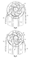
Fig. 8 eine Detailansicht der Irisblende ausFig. 1 (Irisblende geschlossen); -
Fig. 9 eine Detailansicht der Irisblende ausFig. 1 (Irisblende geöffnet); -
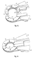
Fig. 10 eine Detailansicht auf eine weitere Ausführungsform einer Irisblende (Irisblende geschlossen); -
Fig. 11 die Irisblende ausFig. 10 (Irisblende geöffnet); -
Fig. 12 eine weitere Ausführungsform der Irisblende in Explosionsansicht; -
Fig. 13 und 14 Detailansichten auf die Irisblende ausFig. 12 . - In der nachfolgenden Beschreibung werden für gleiche und gleichwirkende Teile dieselben Bezugsziffern verwendet.
-
Fig. 1 zeigt ein elektrochirurgisches Instrument 10 zur Herstellung von Anastomosen. Das Instrument 10 umfasst eine Basisplatte 13, auf der Branchen 12, 12' drehbeweglich montiert sind. Eine Verschlussvorrichtung 20 dient zur Betätigung der Branchen 12, 12'. Diese umfasst ein Verschlussbetätigungselement 24, das über eine Kulissenführung mit den Branchen 12, 12' verbunden ist. Das Verschlussbetätigungselement 24 hat im Wesentlichen zwei Positionen, eine erste Position, in der das elektrochirurgische Instrument 10 geöffnet ist und eine zweite Position in der das elektrochirurgische Instrument 10 geschlossen ist. Vorzugsweise ist die Verschlussvorrichtung 20 derart ausgebildet, dass die Branchen 12, 12' in der zweiten Position fixiert sind, so dass ein unbeabsichtigtes Öffnen des elektrochirurgischen Instruments 10 nicht möglich ist (vgl.Fig. 2 ). - Am distalen Ende der Branchen 12, 12' befinden sich Halbblenden 51, 51', die im geschlossenen Zustand des elektrochirurgischen Instruments 10 (vgl.
Fig. 2 und3 ) eine Irisblende 50 ausbilden. - Des Weiteren weist das elektrochirurgische Instrument 10 eine Spannvorrichtung 40 zur Betätigung der Irisblende 50 auf. Diese Spannvorrichtung 40 umfasst ein Spannvorrichtungsbetätigungselement 42, einen Kraftumlenker 44, die drehbeweglich auf der Basisplatte 13 montiert sind, eine Spannfeder 41 und zwei Stellelemente 52, 52'. Die Stellelemente 52, 52' verlaufen jeweils entlang der ersten Branche 12 bzw. der zweiten Branche 12' und übertragen die mit der Spannvorrichtung 40 ausgeübten Kräfte auf die Mechanik der Irisblende 50. Die Spannvorrichtung 40 befindet sich in der geöffneten Position des elektrochirurgischen Instruments 10 ebenfalls in einer geöffneten Stellung (vgl.
Fig. 1 ). In der zweiten, geschlossenen Position des elektrochirurgischen Instruments 10 kann die Spannvorrichtung 40 durch das Betätigen des Spannvorrichtungsbetätigungselements 42 gespannt werden.Fig. 3 zeigt das Spannvorrichtungsbetätigungselement 42 in gespanntem Zustand. Bei einer Betätigung des Spannvorrichtungsbetätigungselements 42 wird die Spannfeder 41, die mit dem Kraftumlenker 44 verbunden ist, gespannt. Es kommt zu einer Rotationsbewegung des Kraftumlenkers 44 um einen Drehpunkt, der zwischen den Branchen 12, 12' liegt. Das Gestänge bzw. die Stellelemente 52, 52', die im Wesentlichen punktsymmetrisch zu diesem Drehpunkt am Kraftumlenker 44 ansetzen, vollziehen eine Translationsbewegung in proximale (Stellelement 52') bzw. distale (Stellelement 52) Richtung. Diese Bewegung führt wie weiter unten näher erläutert zu einem Schließen und Öffnen der Irisblende 50. - Es sei angemerkt, dass die Spannfeder 41 in gespanntem Zustand über die Stellelemente 52, 52' durchgehend eine Kraft auf den Mechanismus der Irisblende 50 ausübt. Der Betrag dieser Kraft lässt sich durch eine Schließkrafteinstellvorrichtung 45 (vgl.
Fig. 3 ) einstellen. Die Ausführungsform des Kraftumlenkers 44 gemäß derFig. 3 umfasst hierfür eine Vielzahl von Bohrungen, die unterschiedliche Abstände zu dem Drehpunkt des Kraftumlenkers 44 aufweisen. Die Spannfeder 41 ist derart ausgebildet, dass sie sich in den einzelnen Bohrungen verankern lässt. Somit setzt die Federkraft der Spannfeder 41 je nach Position in den Bohrungen mit einem sich unterscheidenden Hebel an den Kraftumlenker 44 an. Wie inFig. 1-3 gezeigt überragt der Kraftumlenker 44 die Basisplatte 15 derart, dass diese manuell betätigbar ist. Die Irisblende 50 lässt sich aber auch im nicht-gespannten Zustand über den Kraftumlenker 44, der als Betätigungselement dient, schließen und öffnen. -
Fig. 4 zeigt eine weitere Ausführungsform der Spannvorrichtung 40. Hier umfasst die Schließkrafteinstellvorrichtung 45 eine Stellschraube 46 und einen Winkel 47. Der Winkel 47 ist derart an dem Kraftumlenker 44 befestigt, dass sich dieser durch ein Betätigen der Stellschraube 46 entlang einer Längsachse verschieben lässt. In dem inFig. 4 gezeigten Ausführungsbeispiel setzt die Spannfeder 41 an dem Winkel 47 an. Durch ein Betätigen der Stellschraube 46 lässt sich der Hebel, mit dem die Spannfeder 41 Kraft auf den Kraftumlenker 44 ausübt, stufenlos einstellen. - Ein Weiteres wesentliches Element des elektrochirurgischen Instruments 10 ist eine Positionierungsvorrichtung 30 (vgl.
Fig. 5 ). Diese umfasst eine Hülse 32 zur Aufnahme der Hohlorgane und zwei Hülsenbetätigungsbranchen 35, 35'. Die Positionierungsvorrichtung 30 dient im Wesentlichen dazu, die Hohlorgane im Zentrum der Irisblende 50 zu positionieren. Des Weiteren stellt sie eine Hülsenelektrode 36 bereit. Die Hülse 32 ist im Wesentlichen zylindrisch ausgebildet und umfasst einen ersten Hülsenabschnitt 33 und einen zweiten Hülsenabschnitt 33'. Im Querschnitt, quer zur Längsachse der Hülse 32, bilden die Hülsenabschnitte 33, 33' jeweils einen Halbkreis. Die Hülsenabschnitte 33, 33' sind mit den Hülsenbetätigungsbranchen 35 bzw. 35' verbunden. Diese sind derart drehbeweglich an einem abnehmbaren Abschnitt 13' der Basisplatte 13 befestigt, dass sich die Hülsenabschnitte 33, 33' öffnen und schließen lassen. Im geschlossenen Zustand liegen die Hülsenabschnitte 33, 33' aneinander an und bilden die Hülse 32. Die Positionierungsvorrichtung 30 lässt sich also über die Hülsenbetätigungsbranchen 35, 35' öffnen und schließen. Bevorzugt sind die Hülsenbetätigungsbranchen 35, 35' mit einer Federkraft beaufschlagt, die die Hülsenabschnitte 35, 35' geschlossen hält. Der abnehmbare Abschnitt 13', auf dem Hülsenbetätigungsbranchen 35, 35' drehbeweglich gelagert sind, ist über eine Steckverbindung mit der Basisplatte 13 verbunden. Zur Aufnahme der Hohlorgane lässt sich die Positionierungsvorrichtung 30 von den übrigen Bestandteilen des elektrochirurgischen Instruments 10 ablösen und individuell handhaben. - Die Teilbarkeit der Hülse 32 ist beim Anlegen und Abnehmen des Instruments 10 an dem Hohlorgan von besonderem Vorteil. Um diesen Vorgang weiter zu erleichtern umfasst die Hülse 32 mindestens zwei Dorne 28, die radial zur Längsachse der Hülse 32 und auf den Hülsenabschnitten 33, 33' angeordnet sind. Wird das Hohlorgan oder dessen Abschnitte über die Hülse 32 geschoben, so fixieren die Dorne 28 die übergestülpten Hohlorgane oder Gefäße. Deren Vorschub wird durch die Hülsenbetätigungsbranchen 35, 35' begrenzt.
- Nach der Aufnahme der Hohlorgane lässt sich der abnehmbare Abschnitt 13' wieder mit der Basisplatte 13 verbinden und in eine Position bringen, die dazu geeignet ist, die Abschnitte des Hohlorgans zu verbinden.
- Ein wesentlicher Punkt der vorliegenden Erfindung besteht darin, den Gerätekopf des elektrochirurgischen Instruments 10 in Form einer teilbaren Irisblende aufzubauen. Wie in der
Fig. 1 verdeutlicht, umfasst die Irisblende 50 zwei Halbblenden 51, 51', die im geschlossenen Zustand als eine Irisblende 50 zusammenwirken. Der Aufbau einer Halbblende, nämlich der Halbblende 51 ist in derFig. 6 veranschaulicht. Diese umfasst eine Befestigungsplatte 56, die im Wesentlichen halbkreisförmig ausgebildet und fest mit der ersten Branche 12 verbunden ist. Entlang des Außenrandes dieser Befestigungsplatte 56 erstreckt sich eine ebenfalls halbkreisförmige Schale 57. Die Schale 57 weist eine Öffnung 60 auf, durch die eine sichelförmige Stellscheibe 54 ins Innere der Halbblende 51 ragt. Mittels des Stellelements 52 lässt sich die Stellscheibe 54 derart betätigen, dass diese eine Kreisbewegung um das Zentrum der Irisblende 50 ausführt. Zwischen der Stellscheibe 54 und der Befestigungsplatte 56 sind mehrere Lamellen 53, 53', 53" angeordnet, die abschnittsweise mit der Befestigungsplatte 56 drehbeweglich verbunden sind. Krallen 59, 59' an den Lamellen 53, 53', 53" greifen in entsprechende Lamellenkulissen 58 in der Stellscheibe 54 ein. Die Lamellen 53, 53', 53" sind also derart ausgebildet und angeordnet, dass die Ausrichtung der Lamellen 53, 53', 53" durch die Bewegung der Stellscheibe 54 veränderbar ist. Wie in denFig. 8 und 9 gezeigt, können die Lamellen mindestens zwei Positionen einnehmen. Die Lamellen 53, 53', 53" haben Innenwände 66, die als Elektroden wirken. In einer ersten Position (Fig. 9 ) sind die Lamellen 53, 53' derart positioniert, dass sie kaum über die Stellscheibe 54 herausragen. Es bildet sich eine kreisförmige Durchgangsöffnung, in die die Hülse 32 hineinragt. Zwischen der Hülse 32 und den Innenrändern 66 der Lamellen 53, 53' befindet sich ein Spalt, der zur Aufnahme von Abschnitten der Hohlorgane geeignet ist. - In einer geschlossenen Position ist die Durchgangsöffnung derart verkleinert, dass die Innenränder 66 der Lamellen 53, 53', 53" auf der Hülse 32 aufliegen (vgl.
Fig. 8 ). Soweit sich Gewebeabschnitte der Hohlorgane zwischen den Innenrändern der Lamellen 53, 53', 53" und der Hülse 32 befinden, werden diese mit einer vordefinierten Kraft aneinander und gegen die Hülse 32 gepresst. Diese Kraft lässt sich mit der Schließkrafteinstellvorrichtung 45 einstellen und wird über die Stellelemente 52, 52' auf die Lamellen 53, 53', 53" übertragen. - Die Abdeckungen 55, 55a sind wechselseitig an den Halbblenden 51, 51' angeordnet und schützen deren Mechanik.
-
Fig. 7 zeigt eine weitere Ausgestaltung der Lamellen 53, 53'. Diese sind gestuft ausgebildet und schließen sich derart, dass eine erste Lamelle 53 bei dem Schließvorgang nicht nur auf die zweite Lamelle 53' hinauf gleitet, sondern auch in diese greift. - Eine weitere Ausführungsform der Lamellen 53, 53' lässt sich den
Fig. 10 und 11 entnehmen. DieFig. 10 und 11 zeigen die erfindungsgemäße Irisblende 50 in der Draufsicht, wobei die Irisblende 50 inFig. 10 geschlossen und inFig. 11 geöffnet ist. Um eine bessere Ansicht auf die Mechanik der Irisblende 50 zu haben, ist die Abdeckung 55' inFig. 10 entfernt. Es zeigt sich, dass die Lamellen 53, 53' über T-Anker 59a, 59a' in die Lamellenkulisse 58 der Stellscheibe 54 eingreifen. Die T-Anker 59a, 59a' übernehmen die Funktion der Krallen 59, 59'. Stifte, die auf der Stellscheibe 54 der Halbblenden 51, 51' angeordnet sind und in die Abdeckungen 55, 55' hineinragen, bilden eine Kulissenführung für die Stellscheiben 54. Sie führen die Stellscheiben 54 bei ihrer Rotationsbewegung um das Zentrum der Irisblende 50 und erhöhen dabei den Schließbereich der Lamellen. - Die
Fig. 12 bis 14 zeigen ein weiteres Ausführungsbeispiel der Mechanik der erfindungsgemäßen Irisblende 50 mit einfacherem Aufbau. Um die mechanischen Abläufe erläutern zu können, wird ein Koordinatensystem eingeführt. Die X-Achse dieses Koordinatensystems erstreckt sich im Wesentlichen entlang einer Branche 12. Die Y-Achse steht hierauf quer und zeigt auf das Zentrum der Durchgangsöffnung der Irisblende 50. - Die
Fig. 12 zeigt beispielhaft die erste Halbblende 51 in einer Explosionszeichnung. Ein wesentlicher Unterschied des Ausführungsbeispieles gemäß denFig. 12 bis 14 gegenüber dem derFig. 6 besteht darin, dass die Funktion der Stellscheibe 54 in den Ausführungsbeispielen derFig. 12 bis 14 durch eine Lamelle 53 bis 53", nämlich die Lamelle 53' wahrgenommen wird. Die Befestigungsplatte 56 ist gemäß derFig. 12 ebenfalls mit der ersten Branche 12 fest verbunden. Sie umfasst drei Aussparungen 61, 61', 61", die radial in Richtung auf das Zentrum der Durchgangsöffnung der Irisblende 50 geöffnet sind. In diesen Aussparungen 61, 61', 61" lagern Lamellenstifte 63, 63', 63". Diese sind im Wesentlichen mittig auf den Lamellen 53, 53' 53" angeordnet. Die Aussparungen 61, 61', 61" bilden eine Kulissenführung entlang derer die einzelnen Lamellen 53, 53' 53" auf das Zentrum der Durchgangsöffnung zu bewegt werden können. Die Lamellenstifte 63, 63', 63" sind auf beiden Seiten der Lamellen 53, 53', 53" ausgebildet. Sie greifen auf der einen Seite in die Aussparungen 61, 61', 61" der Befestigungsplatte 56 ein und auf der anderen Seite der Lamellen 53, 53', 53" in Aussparungen 65, 65', 65" der Abdeckung 55. Die Aussparungen 65, 65', 65" der Abdeckungen 55 erstrecken sich ebenfalls im Wesentlichen auf das Zentrum der Durchgangsöffnung der Irisblende 50 zu. Die Lamelle 53' ist starr mit dem Stellelement 52 verbunden und weist hierfür einen entsprechenden Fortsatz auf. Das Stellelement 52 wird entlang der Y-Achse betätigt. Somit kann mittels des Stellelements 52 die zweite Lamelle 53' in Richtung auf das Zentrum der Durchgangsöffnung zu bewegt werden. Die halbkreisförmigen Lamellen 53 bis 53" weisen an ihren Enden jeweils eine Aussparung 64, 64', 64", 64"' auf, die in die Stifte 63, 63', 63" der anderen Lamellen 53 bis 53" eingreifen. Somit besteht eine mechanische Kupplung zwischen der ersten Lamelle 53 und der zweiten Lamelle 53' (Aussparung 64, 64'), die wiederum mit der dritten Lamelle 53" (Aussparung 64", 64"') verbunden ist. Durch die Bewegung der zweiten Lamelle 53' entlang der Y-Achse werden die erste und die dritte Lamelle 53, 53" betätigt und verschoben. Die Kulissenführungen sind ausgebildet, um jede der Lamellen 53 bis 53" auf das Zentrum der Durchgangsöffnung zu zu bewegen, wenn die zweite Lamelle 53' entlang der Y-Achse verschoben wird. Durch eine Gegenbewegung der zweiten Lamelle 53' lässt sich diese Bewegung umkehren. Die Irisblende 50 öffnet sich. - Die zweite Halbblende ist entsprechend symmetrisch aufgebaut. Die
Fig. 13 und 14 zeigen die Halbblenden 51, 51'. Es zeigt sich, dass die erste Lamelle 53 der ersten Halbblende 51 in einem geschlossenen Zustand des elektrochirurgischen Instruments 10 eine mechanische Verbindung mit der ihr gegenüberliegenden Lamelle 53"" eingeht. Es besteht auch hier eine Verbindung zwischen den Lamellenstiften 63, 63', 63" und den Aussparungen 64, 64', 64". Das gleiche gilt für die dritte Lamelle 53". - Die Kupplung der Lamellen 53 bis 53" der ersten Halbblende 51 mit denen der zweiten Halbblende 51 ist lösbar. Im geöffneten Zustand des Instruments 10 hat die Irisblende 50 einen Spalt, durch den das verbundene Hohlorgan von dem Instrument 10 getrennt werden kann. Im geschlossenen Zustand des elektrochirurgischen Instruments 10 bildet sich also ein Ring aus Lamellen 53 bis 53"" aus, der gemäß dem Ausführungsbeispiel der
Fig. 12 bis 14 sechs Lamellen umfasst. Die einzelnen Lamellen 53-53"' stehen jeweils mit den ihnen benachbarten Lamellen 53-53"' in Wirkverbindung. Es bildet sich insgesamt eine Kulissenführung aus, die eine Translationsbewegung der einzelnen Lamellen 53 bis 53"' in Richtung auf das Zentrum der Durchgangsöffnung zu ermöglicht. Die Betätigung der Stellelemente 52, 52' wird also mechanisch auf die einzelnen Lamellen 53 bis 53"' übertragen. - Erfindungsgemäß umfasst die Irisblende 50 eine erste Außenelektrodenanordnung oder Außenelektrode, die Hülse 32 eine Innenelektrodenanordnung, nämlich die Hülsenelektrode 36. Wie in der
Fig. 5 gezeigt, sind diese Elektroden einander benachbart angeordnet. Die Abschnitte von Hohlorganen, die zwischen der Irisblende 50 und der Hülse 32 eingeklemmt sind, können mittels dieser Elektroden miteinander verbunden werden. Hierfür wird ein entsprechender HF-Strom an den Elektroden angelegt. Der HF-Strom führt zu einer Koagulation der Gewebeabschnitte, die sich zwischen den Elektroden befinden. Um den HF-Strom zu applizieren, weist das elektrochirurgische Instrument 10 entsprechende Leiterbahnen und Anschlüsse auf. Beispielsweise kann die Hülsenelektrode 36 über eine Leiterbahn innerhalb der Hülsenbetätigungsbranchen 55, 55' versorgt werden. Eine entsprechende Leiterbahn für die Irisblende kann sich innerhalb der Branchen 12, 12' befinden. - Andererseits können die Branchen 12, 12' und/oder die Hülsenbetätigungsbranchen 53, 53' ganz oder teilweise aus elektrisch leitendem Material ausgebildet sein, um eine entsprechende Leiterbahn bereitzustellen.
- Die einzelnen Lamellen 53 bis 53"' können Elektroden zur Applikation des HF-Stroms umfassen und/oder aus elektrisch leitendem Material ausgebildet sein. Vorzugsweise ist die Basisplatte 13 und der abnehmbare Abschnitt 13' der Basisplatte 13 ein elektrischer Isolator. Somit ist die Leiterbahn der Hülsenelektrode 36 zumindest von der Leiterbahn der Irisblende 50 elektrisch isoliert.
- In einem weiteren Ausführungsbeispiel kann die Basisplatte 13 und/oder der abnehmbare Abschnitt 13' Anschlüsse und elektrische Leiterbahnen umfassen, um die Elektroden zu versorgen.
- Es wurden Ausführungsbeispiele mit vier und acht Lamellen 53 bis 53"" beschrieben. Es sind weitere Ausführungsformen mit einer anderen Anzahl an Lamellen 53 bis 53"" denkbar (z. B. mit mindestens vier Lamellen 53 bis 53"").
- Nachfolgend werden weitere Ausführungsbeispiele genannt.
- Vorrichtung zur Herstellung von Anastomosen zwischen einem ersten und einem zweiten Hohlorgan, die jeweils eine Innen- und eine Außenfläche aufweisen, umfassend
- eine Hülse 32 mit einer Innenelektrodenanordnung 36, über welche das erste Hohlorgan so umgestülpt wird, dass seine Innenfläche nach außen zu liegen kommt, und
- eine Außenelektrodenanordnung 50, die der Innenelektrodenanordnung radial gegenüber liegt und mit dem zweiten Hohlorgan, welches über das erste Hohlorgan geschoben ist, so in elektrischen Kontakt bringbar ist, dass die Elektrodenanordnungen Außenflächen der Hohlorgane kontaktieren,
- Vorrichtung nach Ausführungsbeispiel 1,
dadurch gekennzeichnet, dass
die Lamellen 53 - 53"' nach Art einer Irisblende 50 aufgebaut sind. - Vorrichtung nach einem der vorhergehenden Ausführungsbeispiele,
dadurch gekennzeichnet, dass
die Hülse 32 relativ zur Außenelektrodenanordnung 50 fixiert in einem Halter 34 angeordnet ist. - Vorrichtung nach einem der vorhergehenden Ausführungsbeispiele,
dadurch gekennzeichnet, dass
der Halter 34 zur individuellen Handhabung der Hülse 32 abnehmbar ist. - Vorrichtung nach einem der vorhergehenden Ausführungsbeispiele,
dadurch gekennzeichnet, dass
alle Innenränder 66 der Lamellen 53 - 53"' im Schließzustand zur Hülse 32 einen im Wesentlichen gleichen Abstand aufweisen. - Vorrichtung nach einem der vorhergehenden Ausführungsbeispiele,
dadurch gekennzeichnet, dass
die Durchgangsöffnung hinsichtlich ihres Durchmessers durch Bewegung der Lamellen 53 einstellbar ist. - Vorrichtung nach einem der vorhergehenden Ausführungsbeispiele,
dadurch gekennzeichnet, dass
der Spalt im Öffnungszustand die Außenelektrodenanordnung 50 in zwei Abschnitte oder Hälften 51, 51' teilt, die voneinander weg bewegbar sind. - Vorrichtung nach einem der vorhergehenden Ausführungsbeispiele,
dadurch gekennzeichnet, dass
die Hülse 32 an einer Betätigungseinrichtung 35, 35' gehalten und derart in zwei Teile zerlegbar ausgebildet ist, dass die Teile von einem Schließzustand zur Bildung eines geschlossenen Rohrabschnittes in einen Öffnungszustand zum Abnehmen vom Hohlorgan bringbar sind. - Vorrichtung nach einem der vorhergehenden Ausführungsbeispiele,
dadurch gekennzeichnet, dass
die Betätigungseinrichtung 35, 35' in den Schließzustand vorgespannt ist. - Vorrichtung nach einem der vorhergehenden Ausführungsbeispiele,
dadurch gekennzeichnet, dass
die Lamellen 53 - 53"' durch eine Spanneinrichtung 40 mit einer definierten Kraft in den Schließzustand vorgespannt sind. -
- 10
- Elektrochirurgisches Instrument
- 12, 12'
- Branchen
- 13
- Basisplatte
- 13'
- Abnehmbarer Abschnitt der Basisplatte
- 20
- Verschlussvorrichtung
- 24
- Verschlussbetätigungselement
- 28
- Dorn oder Fixierelement
- 30
- Positionierungsvorrichtung
- 32
- Hülse
- 33, 33'
- Hülsenabschnitt
- 35, 35''
- Hülsenbetätigungsbranche
- 36
- Hülsenelektrode
- 40
- Spannvorrichtung
- 41
- Spannfeder
- 42
- Spannvorrichtungsbetätigungselement
- 44
- Kraftumlenker
- 45
- Schließkrafteinstellvorrichtung
- 46
- Stellschraube
- 47
- Winkel
- 50
- Irisblende
- 51, 51'
- Halbblende
- 52, 52'
- Stellelement
- 53 bis 53'''
- Lamelle
- 54
- Stellscheibe
- 55, 55', 55a
- Abdeckung
- 56
- Befestigungsplatte
- 57
- Schale
- 58
- Lamellenkulisse in der Stellscheibe
- 59, 59'
- Kralle
- 59a, 59a'
- T-Anker
- 60
- Öffnung
- 61, 61', 61''
- Aussparung in der Befestigungsplatte
- 63, 63', 63''
- Lamellenstift
- 64, 64', 64''
- Aussparung an der Lamelle
- 65, 65', 65''
- Aussparung in der Abdeckung
- 66
- Innenrand
die Außenelektrodenanordnung 50 eine Vielzahl von durch mindestens ein Führungsorgan 52, 52' gegeneinander bewegbaren Lamellen 53 - 53"' umfasst, die derart ausgebildet und beweglich angeordnet sind, dass in einem Schließzustand Innenränder 66 der Lamellen 53 - 53"' eine Durchgangsöffnung bilden und am zweiten Hohlorgan anliegen und in einem Öffnungszustand ein von außen zur Durchgangsöffnung führender Spalt zwischen den Lamellen 53 - 53"' gebildet ist, durch den die miteinander verbundenen Hohlorgane aus der Durchgangsöffnung nach außen geführt werden können.
Claims (6)
- Koagulationselektrode, umfassend- einen Lagerring (59),- eine Vielzahl von Lamellen (53 - 53"'), die am Lagerring (59) von einem Öffnungszustand in einen Schließzustand nach Art einer Irisblende verschwenkbar gelagert sind, zur Bildung von Elektrodenabschnitten;- einen Kulissenring (54), der gegenüber dem Lagerring (59) verdrehbar angeordnet und mit Führungsorganen (52, 52') an den Lamellen (53) derart in Eingriff steht, dass bei einem Verdrehen des Kulissenringes (54) gegenüber dem Lagerring die Lamellen (53 - 53"') vom Schließzustand in den Öffnungszustand und umgekehrt verschwenkt werden,
wobei der Lagerring (59) und der Kulissenring (54) jeweils derart zweigeteilt ausgebildet sind, dass sie zusammen mit den am Lagerring (59) gelagerten bzw. mit dem Kulissenring (54) in Eingriff stehenden Lamellen (53 - 53"') voneinander fortbewegbar sind. - Koagulationselektrode nach Anspruch 1,
dadurch gekennzeichnet, dass
der Kulissenring (54) derart zweigeteilt ausgebildet ist, dass dieser einen ersten und einen zweiten Kulissenringabschnitt umfasst, die jeweils getrennt voneinander bewegbar sind. - Koagulationselektrode nach einem der vorhergehenden Ansprüche,
dadurch gekennzeichnet, dass
die Kulissenringabschnitte jeweils getrennt voneinander durch Führungsstangen bewegbar sind. - Koagulationselektrode nach einem der vorhergehenden Ansprüche,
dadurch gekennzeichnet, dass
der Kulissenring (54) eine Stellscheibe umfasst, wobei die Lamellen (53 - 53"") in dem Öffnungszustand kaum über die Stellscheibe (54) hinausragen und derart positioniert sind, dass sich eine kreisförmige Durchgangsöffnung bildet. - Koagulationselektrode nach Anspruch 4,
dadurch gekennzeichnet, dass
die Lamellen (53 - 53"") T-Anker (59a, 59a') umfassen, die in Lamellenkulissen (58) der Stellscheibe eingreifen. - Koagulationselektrode nach einem der vorhergehenden Ansprüche,
dadurch gekennzeichnet, dass
die Anzahl der Lamellen (53 - 53"") größer gleich vier ist.
Priority Applications (1)
| Application Number | Priority Date | Filing Date | Title |
|---|---|---|---|
| PL13191846T PL2710973T3 (pl) | 2008-08-19 | 2009-07-23 | Elektroda koagulacyjna |
Applications Claiming Priority (3)
| Application Number | Priority Date | Filing Date | Title |
|---|---|---|---|
| DE102008038313 | 2008-08-19 | ||
| DE102008048293A DE102008048293B3 (de) | 2008-08-19 | 2008-09-22 | Vorrichtung zur Herstellung von Anastomosen sowie Koagulationselektrode |
| EP09777405.3A EP2341861B1 (de) | 2008-08-19 | 2009-07-23 | Vorrichtung zur herstellung von anastomosen sowie koagulationselektrode |
Related Parent Applications (2)
| Application Number | Title | Priority Date | Filing Date |
|---|---|---|---|
| EP09777405.3A Division EP2341861B1 (de) | 2008-08-19 | 2009-07-23 | Vorrichtung zur herstellung von anastomosen sowie koagulationselektrode |
| EP09777405.3A Division-Into EP2341861B1 (de) | 2008-08-19 | 2009-07-23 | Vorrichtung zur herstellung von anastomosen sowie koagulationselektrode |
Publications (2)
| Publication Number | Publication Date |
|---|---|
| EP2710973A1 true EP2710973A1 (de) | 2014-03-26 |
| EP2710973B1 EP2710973B1 (de) | 2015-01-14 |
Family
ID=41112141
Family Applications (2)
| Application Number | Title | Priority Date | Filing Date |
|---|---|---|---|
| EP09777405.3A Not-in-force EP2341861B1 (de) | 2008-08-19 | 2009-07-23 | Vorrichtung zur herstellung von anastomosen sowie koagulationselektrode |
| EP13191846.8A Not-in-force EP2710973B1 (de) | 2008-08-19 | 2009-07-23 | Koagulationselektrode |
Family Applications Before (1)
| Application Number | Title | Priority Date | Filing Date |
|---|---|---|---|
| EP09777405.3A Not-in-force EP2341861B1 (de) | 2008-08-19 | 2009-07-23 | Vorrichtung zur herstellung von anastomosen sowie koagulationselektrode |
Country Status (7)
| Country | Link |
|---|---|
| US (2) | US9011469B2 (de) |
| EP (2) | EP2341861B1 (de) |
| JP (1) | JP5421991B2 (de) |
| CN (1) | CN102123676B (de) |
| DE (1) | DE102008048293B3 (de) |
| PL (2) | PL2341861T3 (de) |
| WO (1) | WO2010020328A1 (de) |
Families Citing this family (6)
| Publication number | Priority date | Publication date | Assignee | Title |
|---|---|---|---|---|
| US8348128B2 (en) * | 2009-11-11 | 2013-01-08 | Biorep Technologies, Inc. | Anastomosis system and method |
| IT1399861B1 (it) * | 2010-04-30 | 2013-05-09 | I & S Idee & Sviluppo S R L | Applicatore di griffe per giunti vascolari termino - terminali |
| DE102010035470B4 (de) | 2010-08-26 | 2015-08-13 | Fraunhofer-Gesellschaft zur Förderung der angewandten Forschung e.V. | Vorrichtung zum Durchführen einer Seit-zu-Seit- Anastomose |
| DE102012107919A1 (de) | 2012-08-28 | 2014-05-15 | Aesculap Ag | Elektrochirurgisches Instrument zur Herstellung einer End-zu-End-Anastomose |
| US9948074B2 (en) | 2013-10-10 | 2018-04-17 | Schneider Electric Industries Sas | Circuit breaker arrangement |
| CN115508995B (zh) * | 2022-10-19 | 2025-06-17 | 麦克奥迪实业集团有限公司 | 光栏调节机构、转盘式聚光镜及显微镜 |
Citations (3)
| Publication number | Priority date | Publication date | Assignee | Title |
|---|---|---|---|---|
| WO1999059486A2 (en) * | 1998-05-20 | 1999-11-25 | New England Medical Center | System for cardiac arrhythmias treatment by ablation, and tmr |
| WO2003061487A1 (de) | 2002-01-25 | 2003-07-31 | Erbe Elektromedizin Gmbh | Verfahren zur vorrichtung von anastomosen zwischen hohlorganen |
| US20060020263A1 (en) * | 2004-06-02 | 2006-01-26 | Rothstein Paul T | Clamping ablation tool and method |
Family Cites Families (17)
| Publication number | Priority date | Publication date | Assignee | Title |
|---|---|---|---|---|
| CH525668A (de) * | 1970-01-14 | 1972-07-31 | Ceskoslovenska Akademie Ved | Vorrichtung zur nahtlosen Verbindung der Enden eines unterbrochenen, schlauchförmigen Organs bei chirurgischen Operationen |
| US3774615A (en) * | 1971-02-08 | 1973-11-27 | Ceskoslovenska Akademie Ved | Device for connecting or joining the ends of interrupted tubular organs in surgical operations without stitching |
| US4892098A (en) * | 1985-06-26 | 1990-01-09 | Sauer Jude S | Tubular tissue welding device without moving parts |
| US5188638A (en) * | 1992-02-06 | 1993-02-23 | Tzakis Andreas G | Apparatus and method for preforming anastomosis fastener securement of hollow organs |
| US6626901B1 (en) * | 1997-03-05 | 2003-09-30 | The Trustees Of Columbia University In The City Of New York | Electrothermal instrument for sealing and joining or cutting tissue |
| JP3766520B2 (ja) * | 1997-10-06 | 2006-04-12 | オリンパス株式会社 | 血管吻合装置 |
| US20070276363A1 (en) * | 1998-02-12 | 2007-11-29 | Boris E. Paton | Instrument and method for the end-to-end reconnection of intestinal tissues |
| US6562037B2 (en) * | 1998-02-12 | 2003-05-13 | Boris E. Paton | Bonding of soft biological tissues by passing high frequency electric current therethrough |
| US6361559B1 (en) * | 1998-06-10 | 2002-03-26 | Converge Medical, Inc. | Thermal securing anastomosis systems |
| JP2001037770A (ja) * | 1999-07-28 | 2001-02-13 | Olympus Optical Co Ltd | 超音波処置具 |
| JP2003061973A (ja) * | 2001-08-27 | 2003-03-04 | Olympus Optical Co Ltd | 超音波組織溶着装置 |
| US7588565B2 (en) * | 2002-05-15 | 2009-09-15 | Rocky Mountain Biosystems, Inc. | Method and device for anastomoses |
| DE10350709A1 (de) * | 2003-10-30 | 2005-08-18 | Erbe Elektromedizin Gmbh | Vorrichtung zur Koagulation von Gewebe |
| ITBO20030782A1 (it) * | 2003-12-23 | 2005-06-24 | New Age Const And Engineeri Ng S P A | Dispositivo e metodo per anastomosi. |
| DE102009032972A1 (de) * | 2009-07-14 | 2011-01-20 | Erbe Elektromedizin Gmbh | Vorrichtung zur Herstellung von Anastomosen |
| DE102009027813A1 (de) * | 2009-07-17 | 2011-01-27 | Celon Ag Medical Instruments | Anastomosering und Anastomoseringanordnung |
| DE102009059195A1 (de) * | 2009-12-17 | 2011-06-22 | Aesculap AG, 78532 | Chirurgisches System zum Verbinden von Körpergewebe und Verfahren zum Abtrennen überstehenden Gewebes |
-
2008
- 2008-09-22 DE DE102008048293A patent/DE102008048293B3/de not_active Expired - Fee Related
-
2009
- 2009-07-23 CN CN2009801324448A patent/CN102123676B/zh not_active Expired - Fee Related
- 2009-07-23 WO PCT/EP2009/005365 patent/WO2010020328A1/de not_active Ceased
- 2009-07-23 JP JP2011523321A patent/JP5421991B2/ja not_active Expired - Fee Related
- 2009-07-23 EP EP09777405.3A patent/EP2341861B1/de not_active Not-in-force
- 2009-07-23 US US13/059,682 patent/US9011469B2/en not_active Expired - Fee Related
- 2009-07-23 PL PL09777405T patent/PL2341861T3/pl unknown
- 2009-07-23 PL PL13191846T patent/PL2710973T3/pl unknown
- 2009-07-23 EP EP13191846.8A patent/EP2710973B1/de not_active Not-in-force
-
2015
- 2015-03-27 US US14/671,630 patent/US9186147B2/en not_active Expired - Fee Related
Patent Citations (3)
| Publication number | Priority date | Publication date | Assignee | Title |
|---|---|---|---|---|
| WO1999059486A2 (en) * | 1998-05-20 | 1999-11-25 | New England Medical Center | System for cardiac arrhythmias treatment by ablation, and tmr |
| WO2003061487A1 (de) | 2002-01-25 | 2003-07-31 | Erbe Elektromedizin Gmbh | Verfahren zur vorrichtung von anastomosen zwischen hohlorganen |
| US20060020263A1 (en) * | 2004-06-02 | 2006-01-26 | Rothstein Paul T | Clamping ablation tool and method |
Also Published As
| Publication number | Publication date |
|---|---|
| US9186147B2 (en) | 2015-11-17 |
| CN102123676B (zh) | 2013-07-03 |
| PL2341861T3 (pl) | 2014-07-31 |
| US20150257812A1 (en) | 2015-09-17 |
| CN102123676A (zh) | 2011-07-13 |
| EP2710973B1 (de) | 2015-01-14 |
| US20110152862A1 (en) | 2011-06-23 |
| DE102008048293B3 (de) | 2009-10-29 |
| EP2341861B1 (de) | 2014-02-26 |
| JP2012500068A (ja) | 2012-01-05 |
| US9011469B2 (en) | 2015-04-21 |
| EP2341861A1 (de) | 2011-07-13 |
| JP5421991B2 (ja) | 2014-02-19 |
| WO2010020328A1 (de) | 2010-02-25 |
| PL2710973T3 (pl) | 2015-05-29 |
Similar Documents
| Publication | Publication Date | Title |
|---|---|---|
| DE602004006218T2 (de) | Behandlungsinstrument für Endoskop | |
| EP2890307B1 (de) | Elektrochirurgisches instrument zur herstellung einer end-zu-end-anastomose | |
| EP2710973B1 (de) | Koagulationselektrode | |
| DE60312873T2 (de) | Elektrochirurgisches instrument zum verschluss von gefässen | |
| EP2103264B1 (de) | Medizinisches Instrument | |
| EP2512358B1 (de) | Chirurgisches system und steuerungsverfahren für ein chirurgisches instrument zum verbinden von körpergewebeteilen | |
| EP2911595B1 (de) | Anastomoseinstrument mit schwenkbarem amboss | |
| DE202010013152U1 (de) | Chirurgisches System zum Verbinden von Körpergewebe | |
| EP2775941B1 (de) | Anastomosegerät mit kollabierbarem distalem kopfelement | |
| DE102009059195A1 (de) | Chirurgisches System zum Verbinden von Körpergewebe und Verfahren zum Abtrennen überstehenden Gewebes | |
| EP3334351B1 (de) | Vorrichtung zur durchtrennung von gewebeteilen | |
| EP1319372B1 (de) | Vorrichtung zum Halten von Trokarhülsen | |
| EP2453805B1 (de) | Vorrichtung zur herstellung von anastomosen | |
| DE102012103501B4 (de) | Chirurgisches Gerät zur Herstellung einer Tabaksbeutelnaht | |
| EP2837342B1 (de) | Endoskopisches Instrument | |
| DE102021132425B3 (de) | Handhabungsvorrichtung für ein elektrochirurgisches Instrument, Verfahren zur Herstellung einer Handhabungsvorrichtung und elektrochirurgisches Instrument | |
| WO2025119962A1 (de) | Chirurgisches minimalinvasive instrument | |
| DE102012109387A1 (de) | Chirurgisches Instrument und insbesondere elektrochirurgisches Instrument | |
| DE102015103913A1 (de) | Hohlschaftinstrument und insbesondere medizinisch-endoskopisches Hohlschaftinstrument | |
| DE102010016803A1 (de) | Medizinische Fixiereinrichtung | |
| DE202011051933U1 (de) | Chirurgisches Instrument | |
| WO2019185845A1 (de) | Elektroden-applikationsinstrument | |
| DE102012220973A1 (de) | Endoskopisches Instrument |
Legal Events
| Date | Code | Title | Description |
|---|---|---|---|
| PUAI | Public reference made under article 153(3) epc to a published international application that has entered the european phase |
Free format text: ORIGINAL CODE: 0009012 |
|
| AC | Divisional application: reference to earlier application |
Ref document number: 2341861 Country of ref document: EP Kind code of ref document: P |
|
| AK | Designated contracting states |
Kind code of ref document: A1 Designated state(s): AT BE BG CH CY CZ DE DK EE ES FI FR GB GR HR HU IE IS IT LI LT LU LV MC MK MT NL NO PL PT RO SE SI SK SM TR |
|
| 17P | Request for examination filed |
Effective date: 20140331 |
|
| RBV | Designated contracting states (corrected) |
Designated state(s): AT BE BG CH CY CZ DE DK EE ES FI FR GB GR HR HU IE IS IT LI LT LU LV MC MK MT NL NO PL PT RO SE SI SK SM TR |
|
| RIC1 | Information provided on ipc code assigned before grant |
Ipc: A61B 18/14 20060101AFI20140630BHEP |
|
| GRAP | Despatch of communication of intention to grant a patent |
Free format text: ORIGINAL CODE: EPIDOSNIGR1 |
|
| INTG | Intention to grant announced |
Effective date: 20140818 |
|
| GRAS | Grant fee paid |
Free format text: ORIGINAL CODE: EPIDOSNIGR3 |
|
| GRAA | (expected) grant |
Free format text: ORIGINAL CODE: 0009210 |
|
| AC | Divisional application: reference to earlier application |
Ref document number: 2341861 Country of ref document: EP Kind code of ref document: P |
|
| AK | Designated contracting states |
Kind code of ref document: B1 Designated state(s): AT BE BG CH CY CZ DE DK EE ES FI FR GB GR HR HU IE IS IT LI LT LU LV MC MK MT NL NO PL PT RO SE SI SK SM TR |
|
| REG | Reference to a national code |
Ref country code: GB Ref legal event code: FG4D Free format text: NOT ENGLISH |
|
| REG | Reference to a national code |
Ref country code: CH Ref legal event code: EP |
|
| REG | Reference to a national code |
Ref country code: IE Ref legal event code: FG4D Free format text: LANGUAGE OF EP DOCUMENT: GERMAN |
|
| REG | Reference to a national code |
Ref country code: AT Ref legal event code: REF Ref document number: 706583 Country of ref document: AT Kind code of ref document: T Effective date: 20150215 |
|
| REG | Reference to a national code |
Ref country code: DE Ref legal event code: R096 Ref document number: 502009010518 Country of ref document: DE Effective date: 20150226 |
|
| REG | Reference to a national code |
Ref country code: NL Ref legal event code: VDEP Effective date: 20150114 |
|
| REG | Reference to a national code |
Ref country code: PL Ref legal event code: T3 |
|
| REG | Reference to a national code |
Ref country code: LT Ref legal event code: MG4D |
|
| PG25 | Lapsed in a contracting state [announced via postgrant information from national office to epo] |
Ref country code: ES Free format text: LAPSE BECAUSE OF FAILURE TO SUBMIT A TRANSLATION OF THE DESCRIPTION OR TO PAY THE FEE WITHIN THE PRESCRIBED TIME-LIMIT Effective date: 20150114 Ref country code: BG Free format text: LAPSE BECAUSE OF FAILURE TO SUBMIT A TRANSLATION OF THE DESCRIPTION OR TO PAY THE FEE WITHIN THE PRESCRIBED TIME-LIMIT Effective date: 20150414 Ref country code: SE Free format text: LAPSE BECAUSE OF FAILURE TO SUBMIT A TRANSLATION OF THE DESCRIPTION OR TO PAY THE FEE WITHIN THE PRESCRIBED TIME-LIMIT Effective date: 20150114 Ref country code: FI Free format text: LAPSE BECAUSE OF FAILURE TO SUBMIT A TRANSLATION OF THE DESCRIPTION OR TO PAY THE FEE WITHIN THE PRESCRIBED TIME-LIMIT Effective date: 20150114 Ref country code: HR Free format text: LAPSE BECAUSE OF FAILURE TO SUBMIT A TRANSLATION OF THE DESCRIPTION OR TO PAY THE FEE WITHIN THE PRESCRIBED TIME-LIMIT Effective date: 20150114 Ref country code: NO Free format text: LAPSE BECAUSE OF FAILURE TO SUBMIT A TRANSLATION OF THE DESCRIPTION OR TO PAY THE FEE WITHIN THE PRESCRIBED TIME-LIMIT Effective date: 20150414 Ref country code: LT Free format text: LAPSE BECAUSE OF FAILURE TO SUBMIT A TRANSLATION OF THE DESCRIPTION OR TO PAY THE FEE WITHIN THE PRESCRIBED TIME-LIMIT Effective date: 20150114 |
|
| PG25 | Lapsed in a contracting state [announced via postgrant information from national office to epo] |
Ref country code: IS Free format text: LAPSE BECAUSE OF FAILURE TO SUBMIT A TRANSLATION OF THE DESCRIPTION OR TO PAY THE FEE WITHIN THE PRESCRIBED TIME-LIMIT Effective date: 20150514 Ref country code: LV Free format text: LAPSE BECAUSE OF FAILURE TO SUBMIT A TRANSLATION OF THE DESCRIPTION OR TO PAY THE FEE WITHIN THE PRESCRIBED TIME-LIMIT Effective date: 20150114 Ref country code: GR Free format text: LAPSE BECAUSE OF FAILURE TO SUBMIT A TRANSLATION OF THE DESCRIPTION OR TO PAY THE FEE WITHIN THE PRESCRIBED TIME-LIMIT Effective date: 20150415 Ref country code: NL Free format text: LAPSE BECAUSE OF FAILURE TO SUBMIT A TRANSLATION OF THE DESCRIPTION OR TO PAY THE FEE WITHIN THE PRESCRIBED TIME-LIMIT Effective date: 20150114 |
|
| REG | Reference to a national code |
Ref country code: DE Ref legal event code: R097 Ref document number: 502009010518 Country of ref document: DE |
|
| PG25 | Lapsed in a contracting state [announced via postgrant information from national office to epo] |
Ref country code: SK Free format text: LAPSE BECAUSE OF FAILURE TO SUBMIT A TRANSLATION OF THE DESCRIPTION OR TO PAY THE FEE WITHIN THE PRESCRIBED TIME-LIMIT Effective date: 20150114 Ref country code: RO Free format text: LAPSE BECAUSE OF FAILURE TO SUBMIT A TRANSLATION OF THE DESCRIPTION OR TO PAY THE FEE WITHIN THE PRESCRIBED TIME-LIMIT Effective date: 20150114 Ref country code: CZ Free format text: LAPSE BECAUSE OF FAILURE TO SUBMIT A TRANSLATION OF THE DESCRIPTION OR TO PAY THE FEE WITHIN THE PRESCRIBED TIME-LIMIT Effective date: 20150114 Ref country code: DK Free format text: LAPSE BECAUSE OF FAILURE TO SUBMIT A TRANSLATION OF THE DESCRIPTION OR TO PAY THE FEE WITHIN THE PRESCRIBED TIME-LIMIT Effective date: 20150114 Ref country code: EE Free format text: LAPSE BECAUSE OF FAILURE TO SUBMIT A TRANSLATION OF THE DESCRIPTION OR TO PAY THE FEE WITHIN THE PRESCRIBED TIME-LIMIT Effective date: 20150114 |
|
| PLBE | No opposition filed within time limit |
Free format text: ORIGINAL CODE: 0009261 |
|
| STAA | Information on the status of an ep patent application or granted ep patent |
Free format text: STATUS: NO OPPOSITION FILED WITHIN TIME LIMIT |
|
| 26N | No opposition filed |
Effective date: 20151015 |
|
| PG25 | Lapsed in a contracting state [announced via postgrant information from national office to epo] |
Ref country code: MC Free format text: LAPSE BECAUSE OF FAILURE TO SUBMIT A TRANSLATION OF THE DESCRIPTION OR TO PAY THE FEE WITHIN THE PRESCRIBED TIME-LIMIT Effective date: 20150114 Ref country code: SI Free format text: LAPSE BECAUSE OF FAILURE TO SUBMIT A TRANSLATION OF THE DESCRIPTION OR TO PAY THE FEE WITHIN THE PRESCRIBED TIME-LIMIT Effective date: 20150114 |
|
| REG | Reference to a national code |
Ref country code: CH Ref legal event code: PL |
|
| PG25 | Lapsed in a contracting state [announced via postgrant information from national office to epo] |
Ref country code: LU Free format text: LAPSE BECAUSE OF FAILURE TO SUBMIT A TRANSLATION OF THE DESCRIPTION OR TO PAY THE FEE WITHIN THE PRESCRIBED TIME-LIMIT Effective date: 20150723 |
|
| REG | Reference to a national code |
Ref country code: IE Ref legal event code: MM4A |
|
| PG25 | Lapsed in a contracting state [announced via postgrant information from national office to epo] |
Ref country code: CH Free format text: LAPSE BECAUSE OF NON-PAYMENT OF DUE FEES Effective date: 20150731 Ref country code: LI Free format text: LAPSE BECAUSE OF NON-PAYMENT OF DUE FEES Effective date: 20150731 |
|
| REG | Reference to a national code |
Ref country code: FR Ref legal event code: PLFP Year of fee payment: 8 |
|
| PG25 | Lapsed in a contracting state [announced via postgrant information from national office to epo] |
Ref country code: IE Free format text: LAPSE BECAUSE OF NON-PAYMENT OF DUE FEES Effective date: 20150723 |
|
| REG | Reference to a national code |
Ref country code: AT Ref legal event code: MM01 Ref document number: 706583 Country of ref document: AT Kind code of ref document: T Effective date: 20150723 |
|
| PG25 | Lapsed in a contracting state [announced via postgrant information from national office to epo] |
Ref country code: AT Free format text: LAPSE BECAUSE OF NON-PAYMENT OF DUE FEES Effective date: 20150723 |
|
| PG25 | Lapsed in a contracting state [announced via postgrant information from national office to epo] |
Ref country code: MT Free format text: LAPSE BECAUSE OF FAILURE TO SUBMIT A TRANSLATION OF THE DESCRIPTION OR TO PAY THE FEE WITHIN THE PRESCRIBED TIME-LIMIT Effective date: 20150114 |
|
| PG25 | Lapsed in a contracting state [announced via postgrant information from national office to epo] |
Ref country code: SM Free format text: LAPSE BECAUSE OF FAILURE TO SUBMIT A TRANSLATION OF THE DESCRIPTION OR TO PAY THE FEE WITHIN THE PRESCRIBED TIME-LIMIT Effective date: 20150114 Ref country code: HU Free format text: LAPSE BECAUSE OF FAILURE TO SUBMIT A TRANSLATION OF THE DESCRIPTION OR TO PAY THE FEE WITHIN THE PRESCRIBED TIME-LIMIT; INVALID AB INITIO Effective date: 20090723 |
|
| PG25 | Lapsed in a contracting state [announced via postgrant information from national office to epo] |
Ref country code: CY Free format text: LAPSE BECAUSE OF FAILURE TO SUBMIT A TRANSLATION OF THE DESCRIPTION OR TO PAY THE FEE WITHIN THE PRESCRIBED TIME-LIMIT Effective date: 20150114 |
|
| REG | Reference to a national code |
Ref country code: FR Ref legal event code: PLFP Year of fee payment: 9 |
|
| PG25 | Lapsed in a contracting state [announced via postgrant information from national office to epo] |
Ref country code: BE Free format text: LAPSE BECAUSE OF NON-PAYMENT OF DUE FEES Effective date: 20150731 |
|
| PGFP | Annual fee paid to national office [announced via postgrant information from national office to epo] |
Ref country code: GB Payment date: 20170728 Year of fee payment: 9 Ref country code: IT Payment date: 20170720 Year of fee payment: 9 Ref country code: FR Payment date: 20170727 Year of fee payment: 9 |
|
| PGFP | Annual fee paid to national office [announced via postgrant information from national office to epo] |
Ref country code: PL Payment date: 20170707 Year of fee payment: 9 |
|
| PGFP | Annual fee paid to national office [announced via postgrant information from national office to epo] |
Ref country code: DE Payment date: 20170929 Year of fee payment: 9 |
|
| PG25 | Lapsed in a contracting state [announced via postgrant information from national office to epo] |
Ref country code: PT Free format text: LAPSE BECAUSE OF FAILURE TO SUBMIT A TRANSLATION OF THE DESCRIPTION OR TO PAY THE FEE WITHIN THE PRESCRIBED TIME-LIMIT Effective date: 20150114 Ref country code: MK Free format text: LAPSE BECAUSE OF FAILURE TO SUBMIT A TRANSLATION OF THE DESCRIPTION OR TO PAY THE FEE WITHIN THE PRESCRIBED TIME-LIMIT Effective date: 20150114 Ref country code: TR Free format text: LAPSE BECAUSE OF FAILURE TO SUBMIT A TRANSLATION OF THE DESCRIPTION OR TO PAY THE FEE WITHIN THE PRESCRIBED TIME-LIMIT Effective date: 20150114 |
|
| REG | Reference to a national code |
Ref country code: DE Ref legal event code: R119 Ref document number: 502009010518 Country of ref document: DE |
|
| GBPC | Gb: european patent ceased through non-payment of renewal fee |
Effective date: 20180723 |
|
| PG25 | Lapsed in a contracting state [announced via postgrant information from national office to epo] |
Ref country code: GB Free format text: LAPSE BECAUSE OF NON-PAYMENT OF DUE FEES Effective date: 20180723 Ref country code: DE Free format text: LAPSE BECAUSE OF NON-PAYMENT OF DUE FEES Effective date: 20190201 Ref country code: FR Free format text: LAPSE BECAUSE OF NON-PAYMENT OF DUE FEES Effective date: 20180731 |
|
| PG25 | Lapsed in a contracting state [announced via postgrant information from national office to epo] |
Ref country code: IT Free format text: LAPSE BECAUSE OF NON-PAYMENT OF DUE FEES Effective date: 20180723 |
|
| PG25 | Lapsed in a contracting state [announced via postgrant information from national office to epo] |
Ref country code: PL Free format text: LAPSE BECAUSE OF NON-PAYMENT OF DUE FEES Effective date: 20180723 |