EP2710942A1 - Tabletop grill with removable grill plates - Google Patents
Tabletop grill with removable grill plates Download PDFInfo
- Publication number
- EP2710942A1 EP2710942A1 EP13186026.4A EP13186026A EP2710942A1 EP 2710942 A1 EP2710942 A1 EP 2710942A1 EP 13186026 A EP13186026 A EP 13186026A EP 2710942 A1 EP2710942 A1 EP 2710942A1
- Authority
- EP
- European Patent Office
- Prior art keywords
- grill
- housing
- tabletop
- grill plate
- magnet device
- Prior art date
- Legal status (The legal status is an assumption and is not a legal conclusion. Google has not performed a legal analysis and makes no representation as to the accuracy of the status listed.)
- Withdrawn
Links
Images





Classifications
-
- A—HUMAN NECESSITIES
- A47—FURNITURE; DOMESTIC ARTICLES OR APPLIANCES; COFFEE MILLS; SPICE MILLS; SUCTION CLEANERS IN GENERAL
- A47J—KITCHEN EQUIPMENT; COFFEE MILLS; SPICE MILLS; APPARATUS FOR MAKING BEVERAGES
- A47J37/00—Baking; Roasting; Grilling; Frying
- A47J37/06—Roasters; Grills; Sandwich grills
- A47J37/0611—Roasters; Grills; Sandwich grills the food being cooked between two heating plates, e.g. waffle-irons
-
- A—HUMAN NECESSITIES
- A47—FURNITURE; DOMESTIC ARTICLES OR APPLIANCES; COFFEE MILLS; SPICE MILLS; SUCTION CLEANERS IN GENERAL
- A47J—KITCHEN EQUIPMENT; COFFEE MILLS; SPICE MILLS; APPARATUS FOR MAKING BEVERAGES
- A47J37/00—Baking; Roasting; Grilling; Frying
- A47J37/06—Roasters; Grills; Sandwich grills
- A47J37/07—Roasting devices for outdoor use; Barbecues
- A47J37/0704—Roasting devices for outdoor use; Barbecues with horizontal fire box
- A47J37/0709—Roasting devices for outdoor use; Barbecues with horizontal fire box with electric heating elements
-
- A—HUMAN NECESSITIES
- A47—FURNITURE; DOMESTIC ARTICLES OR APPLIANCES; COFFEE MILLS; SPICE MILLS; SUCTION CLEANERS IN GENERAL
- A47J—KITCHEN EQUIPMENT; COFFEE MILLS; SPICE MILLS; APPARATUS FOR MAKING BEVERAGES
- A47J37/00—Baking; Roasting; Grilling; Frying
- A47J37/06—Roasters; Grills; Sandwich grills
- A47J37/067—Horizontally disposed broiling griddles
- A47J37/0676—Horizontally disposed broiling griddles electrically heated
-
- B—PERFORMING OPERATIONS; TRANSPORTING
- B23—MACHINE TOOLS; METAL-WORKING NOT OTHERWISE PROVIDED FOR
- B23P—METAL-WORKING NOT OTHERWISE PROVIDED FOR; COMBINED OPERATIONS; UNIVERSAL MACHINE TOOLS
- B23P11/00—Connecting or disconnecting metal parts or objects by metal-working techniques not otherwise provided for
-
- A—HUMAN NECESSITIES
- A47—FURNITURE; DOMESTIC ARTICLES OR APPLIANCES; COFFEE MILLS; SPICE MILLS; SUCTION CLEANERS IN GENERAL
- A47J—KITCHEN EQUIPMENT; COFFEE MILLS; SPICE MILLS; APPARATUS FOR MAKING BEVERAGES
- A47J37/00—Baking; Roasting; Grilling; Frying
- A47J37/06—Roasters; Grills; Sandwich grills
-
- Y—GENERAL TAGGING OF NEW TECHNOLOGICAL DEVELOPMENTS; GENERAL TAGGING OF CROSS-SECTIONAL TECHNOLOGIES SPANNING OVER SEVERAL SECTIONS OF THE IPC; TECHNICAL SUBJECTS COVERED BY FORMER USPC CROSS-REFERENCE ART COLLECTIONS [XRACs] AND DIGESTS
- Y10—TECHNICAL SUBJECTS COVERED BY FORMER USPC
- Y10T—TECHNICAL SUBJECTS COVERED BY FORMER US CLASSIFICATION
- Y10T29/00—Metal working
- Y10T29/49—Method of mechanical manufacture
- Y10T29/49826—Assembling or joining
Definitions
- the present invention relates generally to heating appliances and, more particularly, to a tabletop grill for use in heating a food product.
- Many conventional tabletop grills have an upper housing and a lower housing that are connected together via a hinge in a clamshell-type configuration.
- a grill plate covers each of the housings, and a heating element is disposed within each of the housings for heating the grill plate and, therefore, a food product contacting the grill plate.
- the plates are removable from their associated housings for cleaning.
- the plates are typically removable using a latch mechanism that is susceptible to malfunction or breakage. It would be useful, therefore, to provide a tabletop grill with a simpler and more reliable device for removably mounting the grill plates on the housings.
- a tabletop grill generally comprises a housing, a heating element disposed within the housing, and a grill plate configured to be removably mounted on the housing.
- the grill plate and the housing are magnetically connectable to retain the grill plate on the housing.
- a grill plate for a tabletop grill that includes a housing having a magnet device generally comprises a ferromagnetic material configured for making a magnetic connection with the magnet device of the housing.
- a tabletop grill generally comprises a bottom grill unit comprising a bottom housing, a bottom reflector pan disposed within the bottom housing, a bottom heating element disposed within the bottom housing, and a bottom grill plate mounted on the bottom housing such that the bottom heating element is situated between the bottom reflector pan and the bottom grill plate.
- the tabletop grill further comprises a top grill unit comprising a top housing, a top reflector pan disposed within the top housing, a top heating element disposed within the top housing, and a top grill plate mounted on the top housing such that the top heating element is situated between the top reflector pan and the top grill plate.
- the tabletop grill also comprises a hinge connecting the bottom grill unit to the top grill unit such that the top grill unit is pivotable relative to the bottom grill unit so as to change an orientation of the top grill plate relative to the bottom grill plate.
- Each of the bottom grill plate and the top grill plate comprises a pair of handles, and each of the handles has a gripping segment, a plurality of spaced-apart alignment segments that define a plurality of gaps, and a ferromagnetic material associated with one of the alignment segments.
- Each of the bottom housing and the top housing comprises a pair of alignment assemblies each configured for engaging one of the handles.
- Each of the alignment assemblies has a sleeve, a magnet device loosely disposed within the sleeve, and a plurality of alignment projections projecting from the sleeve each for insertion into one of the gaps of the associated handle such that the magnet device of each alignment assembly magnetically connects to the ferromagnetic material of the associated handle to removably retain each of the grill plates on its respective housing.
- a method of assembling a tabletop grill generally comprises providing a housing in which a heating element is disposed. The method further includes magnetically connecting a grill plate to the housing over the heating element.
- a tabletop grill according to the illustrated embodiment is indicated generally by 100.
- the illustrated grill 100 comprises a bottom grill unit (indicated generally by 102) and a top grill unit (indicated generally by 104) that are connected together via a hinge 106.
- the bottom grill unit 102 has a bottom grill plate 108
- the top grill unit 104 has a top grill plate 110.
- the grill 100 may be any suitable tabletop heating appliance that functions as described herein (e.g., a griddle, a waffle iron, etc.).
- the hinge 106 is configured to enable the top grill unit 104 to be opened and maintained in a position that orients the top grill plate 110 at about 90° relative to the bottom grill plate 108.
- the hinge 106 is also configured to enable the top grill unit 104 to be pivoted from the position of the top grill plate 110 being oriented at about 90° relative to the bottom grill plate 108 into a position in which the top grill plate 110 is oriented at about 180° relative to the bottom grill plate 108 (e.g., a position in which the grill 100 is open, with the bottom grill unit 102 and the top grill unit 104 both contacting the tabletop or other support surface).
- the hinge 106 is configured to maintain the top grill unit 104 in a first open position in which the top grill plate 110 is oriented at about 105° relative to the bottom grill plate 108, and the hinge 106 is further configured to permit pivoting of the top grill unit 104 from the first open position into a second open position in which the top grill plate 110 is oriented at about 196° relative to the bottom grill plate 108.
- the hinge 106 may be configured to enable other desired orientations of the grill plates 108, 110 relative to one another.
- the illustrated top grill unit 104 is provided with an extension 112 that functions as a handle for lifting the top grill unit 104 away from the bottom grill unit 102 and into an orientation at which the grill plates 108, 110 are angled at about 90° relative to one another, and also functions as a foot for supporting the top grill unit 104 on the tabletop surface (or other suitable support surface) when the grill plates 108, 110 are angled at about 180° relative to one another.
- the illustrated hinge 106 is configured such that the top grill unit 104 is floatable relative to the bottom grill unit 102 within a predetermined distance (e.g., about 1").
- the floatable hinge 106 permits the top grill unit 104 to rise within the predetermined distance in order to better accommodate the thicker food product.
- the illustrated grill 100 therefore facilitates pivoting the top grill plate 110 relative to the bottom grill plate 108 within a wider range of motion, as well as accommodating thicker food products (e.g., thicker cuts of meat or thicker sandwiches) between the grill plates 108, 110.
- the illustrated grill 100 is configured as a horizontal grill (i.e., a device configured to heat a food product with the grill plate(s) 108, 110 oriented substantially parallel to the tabletop or other suitable support surface).
- the grill 100 may be a vertical grill in other embodiments (i.e., a device configured to heat a food product with the grill plate(s) 108, 110 oriented substantially perpendicular to the tabletop or other suitable support surface).
- the grill 100 may have only one grill plate (e.g., only the bottom grill plate 108, with no top grill unit 104), or the grill 100 may be configured to heat a food product with the grill plate(s) 108, 110 oriented in any suitable manner.
- the bottom grill unit 102 is shown in more detail. However, it should be noted that the top grill unit 104 is to be constructed in much the same manner as the bottom grill unit 102.
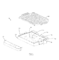
- the bottom grill unit 102 includes a thermostat 114, a reflector pan 116, and a heating element 118 that are disposed one atop of the other within a cavity 120 ( Fig. 5 ) of a housing 122 beneath the grill plate 108 such that the heating element 118 is disposed between the reflector pan 116 and the grill plate 108.
- the thermostat 114 and the heating element 118 are configured to be provided electrical power from a source of electricity in any suitable manner (e.g., via electrical cords plugged into an electrical outlet).
- the bottom grill unit 102 also includes a grease tray 113 suitably arranged to collect grease during a grilling operation.
- the reflector pan 116 is configured to be shallow and has a substantially flat bottom segment 124 and oblique side segments 126 such that heat radiated downward or sideways from the heating element 118 is reflected toward the underside of the grill plate 108 in a more evenly distributed manner, thereby facilitating optimized heating of the grill plate 108.
- the heating element 118, the reflector pan 116, the grill plate 108, and/or the thermostat 114 may be suitably configured to optimize heating of the grill plate 108 (e.g., the reflector pan 116 may be contoured in another manner, or the heating element 118 may be positioned in another location).
- the housing 122 of the bottom grill unit 102 is configured with a lip 128 projecting from a step 130 about at least a portion of the periphery of the cavity 120.
- the grill plate 108 is also configured with a lip 132 ( Fig. 8 ) that extends about at least a portion of the plate periphery.
- the lip 132 of the grill plate 108 is seated on (or closely adjacent to) the step 130 of the housing 122 such that the lip 132 of the grill plate 108 overlaps the lip 128 of the housing 122 to facilitate retaining (e.g., sealing) heat within the cavity 120 during grilling, thereby providing a more efficient grilling operation (e.g. faster preheating, improved temperature presetting, etc.).
- the bottom grill unit 102 facilitates preheating the grill plate 108 faster; distributing heat along the grill plate 108 in a more even manner; expediting heat recovery and cooking time; and more effectively presetting and maintaining an optimal cooking temperature (e.g., 390°F, 375°F, etc.).
- the grill plate 108 and the housing 122 may be suitably configured for interacting (e.g., overlapping) with one another in any manner that facilitates retaining heat within the cavity 120 during grilling.
- the housing 122 further includes a pair of alignment assemblies 200 for removably seating the grill plate 108 on the housing 122.
- Each alignment assembly 200 includes a rigid sleeve 202 (or shell) defining an internal pocket 204 that has an open top 206 and an open bottom 208.
- a closure 210 (not shown in Fig. 6 ) is fastened to the sleeve 202 (e.g., via screws 212 shown in Figs. 9-11 ) to cover the open bottom 208, and a pair of spaced alignment projections 214 flank the open top 206.
- the alignment assembly 200 also includes a magnet device 216 (shown in Figs. 9-11 ) situated within the pocket 204, as set forth in more detail below.
- the grill plate 108 has a pair of handles 218.
- Each handle 218 has a gripping segment 220 and three alignment segments 222 extending substantially perpendicular to the gripping segment 220, thereby defining a pair of gaps (or apertures) 224 for receiving the projections 214 of one of the alignment assemblies 200 to properly align the handle 218 (and, therefore, the entire grill plate 108) on the housing 122 when the grill plate 108 is seated on the housing 122.
- a ferromagnetic material 226 e.g., a metallic material
- the ferromagnetic material 226 may be a metallic plate that is fastened to the underside of a plastic handle 218.
- other embodiments of the grill 100 may suitably include: a cord wrapping assembly; dishwasher-safe materials; no handles, integrated handles, or extended phenolic handles; a grill plate coating; a temperature preset device; an optimized grill slope; optimized grill plate rib configurations; or grill plates having optimally sized cooking areas.
- FIG. 9-11 one of the alignment assemblies 200 is shown in schematic cross-section during its various states of operation.
- the sleeve 202 has a pair of internal overhang surfaces 230 adjacent the open top 206 ( Fig. 9 ), and the magnet device 216 is disposed within the pocket 204 beneath the overhanging surfaces 230.
- the pocket 204 has a lengthwise dimension L and a widthwise dimension W.
- the magnet device 216 is sized to have a loose fitting disposition within the pocket 204 (e.g., the illustrated magnet device 216 is sized to be movable lengthwise and widthwise within the pocket 204).
- the magnet device 216 may be any object that produces magnetism.
- the magnet device 216 may be a magnetic catch made up of a ceramic magnet fastened between two metallic plates such that the ceramic magnet transfers magnetism to the metallic plates, thereby reducing wear on the ceramic magnet by enabling the metallic plates (rather than the ceramic magnet) to be used for contacting the structure to which the magnet device is to be repeatedly coupled (e.g., the handle 218).
- the illustrated alignment assembly 200 is in a first operative state, in which the magnet device 216 is at rest on the closure 210 within the pocket 204 because the grill plate 108 has yet to be mounted on the housing 122.
- the magnet device 216 may not necessarily be at rest on the closure 210 in every instance (e.g., the magnet device 216 of the top grill unit 104 may be seated on a sidewall of its associated sleeve 202 when the top grill unit 104 is hinged open at an angle less than 180° with the top grill plate 110 removed).
- the gaps 224 of the handle 218 are aligned with the projections 214 of the alignment assembly 200.
- the handle 218 is then lowered toward the alignment assembly 200 until the projections 214 of the alignment assembly 200 are inserted into the gaps 224 of the handle 218.
- the middle alignment member 228 is disposed within the open top 206 of the sleeve 202 such that the middle alignment member 228 (e.g., the ferromagnetic material 226) is at least partially beneath the overhang surfaces 230.
- the magnetic attraction between the ferromagnetic material 226 and the magnet device 216 causes the magnet device 216 to be set into motion in the lengthwise dimension L, thereby displacing the magnet device 216 from being at rest on the closure 210 (or any other suitable surface within the pocket 204) to being suspended above (or otherwise further distanced away from) the closure 210 in magnetic connection with the ferromagnetic material 226 of the handle 218.
- the overhang surfaces 230 act as limit stops for the lengthwise displacement of the magnet device 216, thereby preventing withdrawal of the magnet device 216 from the pocket 204 and, therefore, inhibiting removal of the grill plate 108 from the housing 122 until the magnetic connection between the magnet device 216 and the ferromagnetic material 226 has been broken.
- the grill plate 108 is mechanically and magnetically stabilized on the housing 122. More specifically, the handles 218 are inhibited from moving laterally (i.e., are inhibited from moving in a plane substantially parallel to the widthwise dimension W of the pocket 204) by virtue of the intersticed arrangement of the alignment segments 222 and the alignment projections 214, and the handles 218 are also inhibited from moving vertically (i.e., are inhibited from moving in a plane substantially parallel to the lengthwise dimension L of the pocket 204) by virtue of the magnetic connection between the magnet devices 216 to their associated ferromagnetic materials 226.
- the handle 218 is to be lifted away from the sleeve 202 with a force stronger than the magnetic connection between the magnet device 216 and the ferromagnetic material 226.
- the magnet device 216 travels conjointly with the handle 218 in the lengthwise dimension L until the magnet device 216 is stopped by the overhang surfaces 230, at which point the magnetic connection between the magnet device 216 and the ferromagnetic material 226 will be broken.
- the grill plate 108 may be completely removed from the housing 122, and the magnet device 216 returns to its state of rest within the pocket 204 (as shown in Fig. 9 ).
- the grill plate 108 may removably mount on the housing 122 via any suitable magnetic configuration (e.g., the handles 218 may include the magnet device 216, the sleeve may include the ferromagnetic material 226, and/or the magnetic connection may be established at a location other than at the handles 218 of the grill plate 108).
- the handles 218 may include the magnet device 216
- the sleeve may include the ferromagnetic material 226, and/or the magnetic connection may be established at a location other than at the handles 218 of the grill plate 108).
- the alignment segments 222 of the handle 218 may become deformed (e.g., bent or twisted) over time, and the orientation of the ferromagnetic material 226 (or other suitable engagement surface for the magnet device 216) may therefore become skewed.
- repeated use of the grill 100 may cause the ferromagnetic material 226 (or other suitable engagement surface for the magnet device 216 on the handle 218) to become titled or oblique with respect to the widthwise dimension W of the pocket 204.
- the magnet device 216 is loosely fitted within the pocket 204 (e.g., is permitted to move in the lengthwise dimension L and the widthwise dimension W), the magnet device 216 is therefore given the tolerance to orient itself within the pocket 204 for a more desirable interface with the handle 218 (and, therefore, a stronger magnetic connection with the ferromagnetic material 226 of the middle alignment member 228).
- This self-orienting capability of the magnet device 216 within the pocket 204 enables the alignment assembly 200 to sufficiently retain the grill plate 108 on the housing 122 even when the orientation of the ferromagnetic material 226 (or other magnet device engagement surface) is skewed.
Landscapes
- Engineering & Computer Science (AREA)
- Food Science & Technology (AREA)
- Mechanical Engineering (AREA)
- Baking, Grill, Roasting (AREA)
Abstract
Description
- The present invention relates generally to heating appliances and, more particularly, to a tabletop grill for use in heating a food product.
- Many conventional tabletop grills have an upper housing and a lower housing that are connected together via a hinge in a clamshell-type configuration. A grill plate covers each of the housings, and a heating element is disposed within each of the housings for heating the grill plate and, therefore, a food product contacting the grill plate. In some conventional grills, the plates are removable from their associated housings for cleaning. However, the plates are typically removable using a latch mechanism that is susceptible to malfunction or breakage. It would be useful, therefore, to provide a tabletop grill with a simpler and more reliable device for removably mounting the grill plates on the housings.
- In one embodiment, a tabletop grill generally comprises a housing, a heating element disposed within the housing, and a grill plate configured to be removably mounted on the housing. The grill plate and the housing are magnetically connectable to retain the grill plate on the housing.
- In another embodiment, a grill plate for a tabletop grill that includes a housing having a magnet device generally comprises a ferromagnetic material configured for making a magnetic connection with the magnet device of the housing.
- In yet another embodiment, a tabletop grill generally comprises a bottom grill unit comprising a bottom housing, a bottom reflector pan disposed within the bottom housing, a bottom heating element disposed within the bottom housing, and a bottom grill plate mounted on the bottom housing such that the bottom heating element is situated between the bottom reflector pan and the bottom grill plate. The tabletop grill further comprises a top grill unit comprising a top housing, a top reflector pan disposed within the top housing, a top heating element disposed within the top housing, and a top grill plate mounted on the top housing such that the top heating element is situated between the top reflector pan and the top grill plate. The tabletop grill also comprises a hinge connecting the bottom grill unit to the top grill unit such that the top grill unit is pivotable relative to the bottom grill unit so as to change an orientation of the top grill plate relative to the bottom grill plate. Each of the bottom grill plate and the top grill plate comprises a pair of handles, and each of the handles has a gripping segment, a plurality of spaced-apart alignment segments that define a plurality of gaps, and a ferromagnetic material associated with one of the alignment segments. Each of the bottom housing and the top housing comprises a pair of alignment assemblies each configured for engaging one of the handles. Each of the alignment assemblies has a sleeve, a magnet device loosely disposed within the sleeve, and a plurality of alignment projections projecting from the sleeve each for insertion into one of the gaps of the associated handle such that the magnet device of each alignment assembly magnetically connects to the ferromagnetic material of the associated handle to removably retain each of the grill plates on its respective housing.
- In yet another embodiment, a method of assembling a tabletop grill generally comprises providing a housing in which a heating element is disposed. The method further includes magnetically connecting a grill plate to the housing over the heating element.
-
-
Figure 1 is a perspective view of one embodiment of a tabletop grill; -
Figure 2 is a side view of the tabletop grill ofFigure 1 ; -
Figure 3 is a perspective view of a bottom grill unit of the tabletop grill ofFigure 1 ; -
Figure 4 is an exploded view of the bottom grill unit ofFigure 3 ; -
Figure 5 is a top perspective view of a housing of the bottom grill unit ofFigure 3 ; -
Figure 6 is a bottom perspective view of the housing ofFigure 5 with a pair of closures detached from their associated sleeves; -
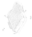
Figure 7 is a top perspective view of a grill plate of the bottom grill unit ofFigure 3 ; -
Figure 8 is a bottom perspective view of the grill plate ofFigure 7 ; -
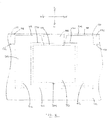
Figure 9 is a schematic cross-sectional view of a grill plate alignment assembly of the housing ofFigure 5 ; -
Figure 10 is a schematic cross-sectional view of the grill plate alignment assembly ofFigure 9 operatively engaged with a handle of the grill plate ofFigure 7 ; and -
Figure 11 is another schematic cross-sectional view of the grill plate alignment assembly ofFigure 9 operatively engaged with a handle of the grill plate ofFigure 7 . - Corresponding reference characters indicate corresponding parts throughout the several views of the drawings.
- Referring to the drawings, and in particular to
Figs. 1 and2 , a tabletop grill according to the illustrated embodiment is indicated generally by 100. The illustratedgrill 100 comprises a bottom grill unit (indicated generally by 102) and a top grill unit (indicated generally by 104) that are connected together via a hinge 106. Thebottom grill unit 102 has abottom grill plate 108, and thetop grill unit 104 has atop grill plate 110. Notably, in other embodiments, thegrill 100 may be any suitable tabletop heating appliance that functions as described herein (e.g., a griddle, a waffle iron, etc.). - In the illustrated embodiment, the hinge 106 is configured to enable the
top grill unit 104 to be opened and maintained in a position that orients thetop grill plate 110 at about 90° relative to thebottom grill plate 108. The hinge 106 is also configured to enable thetop grill unit 104 to be pivoted from the position of thetop grill plate 110 being oriented at about 90° relative to thebottom grill plate 108 into a position in which thetop grill plate 110 is oriented at about 180° relative to the bottom grill plate 108 (e.g., a position in which thegrill 100 is open, with thebottom grill unit 102 and thetop grill unit 104 both contacting the tabletop or other support surface). For example, in one suitable embodiment, the hinge 106 is configured to maintain thetop grill unit 104 in a first open position in which thetop grill plate 110 is oriented at about 105° relative to thebottom grill plate 108, and the hinge 106 is further configured to permit pivoting of thetop grill unit 104 from the first open position into a second open position in which thetop grill plate 110 is oriented at about 196° relative to thebottom grill plate 108. Suitably, other embodiments of the hinge 106 may be configured to enable other desired orientations of thegrill plates - In that regard, the illustrated
top grill unit 104 is provided with anextension 112 that functions as a handle for lifting thetop grill unit 104 away from thebottom grill unit 102 and into an orientation at which thegrill plates top grill unit 104 on the tabletop surface (or other suitable support surface) when thegrill plates top grill unit 104 is floatable relative to thebottom grill unit 102 within a predetermined distance (e.g., about 1"). Thus, when a thicker food product is placed on thebottom grill plate 108 and thetop grill unit 104 is hinged toward thebottom grill unit 102 to close thegrill 100, the floatable hinge 106 permits thetop grill unit 104 to rise within the predetermined distance in order to better accommodate the thicker food product. The illustratedgrill 100 therefore facilitates pivoting thetop grill plate 110 relative to thebottom grill plate 108 within a wider range of motion, as well as accommodating thicker food products (e.g., thicker cuts of meat or thicker sandwiches) between thegrill plates - As set forth above, the illustrated
grill 100 is configured as a horizontal grill (i.e., a device configured to heat a food product with the grill plate(s) 108, 110 oriented substantially parallel to the tabletop or other suitable support surface). However, it is contemplated that thegrill 100 may be a vertical grill in other embodiments (i.e., a device configured to heat a food product with the grill plate(s) 108, 110 oriented substantially perpendicular to the tabletop or other suitable support surface). Alternatively, thegrill 100 may have only one grill plate (e.g., only thebottom grill plate 108, with no top grill unit 104), or thegrill 100 may be configured to heat a food product with the grill plate(s) 108, 110 oriented in any suitable manner. - Referring now to
Figs. 3-8 , thebottom grill unit 102 is shown in more detail. However, it should be noted that thetop grill unit 104 is to be constructed in much the same manner as thebottom grill unit 102. In the illustrated embodiment, thebottom grill unit 102 includes athermostat 114, a reflector pan 116, and a heating element 118 that are disposed one atop of the other within a cavity 120 (Fig. 5 ) of ahousing 122 beneath thegrill plate 108 such that the heating element 118 is disposed between the reflector pan 116 and thegrill plate 108. Thethermostat 114 and the heating element 118 are configured to be provided electrical power from a source of electricity in any suitable manner (e.g., via electrical cords plugged into an electrical outlet). Thebottom grill unit 102 also includes agrease tray 113 suitably arranged to collect grease during a grilling operation. - The reflector pan 116 is configured to be shallow and has a substantially
flat bottom segment 124 and oblique side segments 126 such that heat radiated downward or sideways from the heating element 118 is reflected toward the underside of thegrill plate 108 in a more evenly distributed manner, thereby facilitating optimized heating of thegrill plate 108. In other embodiments, the heating element 118, the reflector pan 116, thegrill plate 108, and/or thethermostat 114 may be suitably configured to optimize heating of the grill plate 108 (e.g., the reflector pan 116 may be contoured in another manner, or the heating element 118 may be positioned in another location). - In the illustrated embodiments, the
housing 122 of thebottom grill unit 102 is configured with alip 128 projecting from astep 130 about at least a portion of the periphery of thecavity 120. Correspondingly, thegrill plate 108 is also configured with a lip 132 (Fig. 8 ) that extends about at least a portion of the plate periphery. When thegrill plate 108 is seated on thehousing 122, thelip 132 of thegrill plate 108 is seated on (or closely adjacent to) thestep 130 of thehousing 122 such that thelip 132 of thegrill plate 108 overlaps thelip 128 of thehousing 122 to facilitate retaining (e.g., sealing) heat within thecavity 120 during grilling, thereby providing a more efficient grilling operation (e.g. faster preheating, improved temperature presetting, etc.). In this manner, thebottom grill unit 102 facilitates preheating thegrill plate 108 faster; distributing heat along thegrill plate 108 in a more even manner; expediting heat recovery and cooking time; and more effectively presetting and maintaining an optimal cooking temperature (e.g., 390°F, 375°F, etc.). In other embodiments, however, thegrill plate 108 and thehousing 122 may be suitably configured for interacting (e.g., overlapping) with one another in any manner that facilitates retaining heat within thecavity 120 during grilling. - With particular reference to
Figs. 5 and6 , thehousing 122 further includes a pair ofalignment assemblies 200 for removably seating thegrill plate 108 on thehousing 122. Eachalignment assembly 200 includes a rigid sleeve 202 (or shell) defining aninternal pocket 204 that has an open top 206 and anopen bottom 208. A closure 210 (not shown inFig. 6 ) is fastened to the sleeve 202 (e.g., viascrews 212 shown inFigs. 9-11 ) to cover theopen bottom 208, and a pair of spacedalignment projections 214 flank the open top 206. Thealignment assembly 200 also includes a magnet device 216 (shown inFigs. 9-11 ) situated within thepocket 204, as set forth in more detail below. - As shown in
Figs. 7 and8 , thegrill plate 108 has a pair ofhandles 218. Each handle 218 has agripping segment 220 and threealignment segments 222 extending substantially perpendicular to the grippingsegment 220, thereby defining a pair of gaps (or apertures) 224 for receiving theprojections 214 of one of thealignment assemblies 200 to properly align the handle 218 (and, therefore, the entire grill plate 108) on thehousing 122 when thegrill plate 108 is seated on thehousing 122. Notably, a ferromagnetic material 226 (e.g., a metallic material) is disposed on an underside of, or within, themiddle alignment segment 228 of thehandle 218. For example, as illustrated inFig. 8 , the ferromagnetic material 226 may be a metallic plate that is fastened to the underside of aplastic handle 218. - Moreover, with general reference again to
Figs. 1-8 , other embodiments of thegrill 100 may suitably include: a cord wrapping assembly; dishwasher-safe materials; no handles, integrated handles, or extended phenolic handles; a grill plate coating; a temperature preset device; an optimized grill slope; optimized grill plate rib configurations; or grill plates having optimally sized cooking areas. - Referring now to
Figs. 9-11 , one of thealignment assemblies 200 is shown in schematic cross-section during its various states of operation. - Before describing the functionality of the illustrated
alignment assembly 200, it should be noted that thesleeve 202 has a pair of internal overhang surfaces 230 adjacent the open top 206 (Fig. 9 ), and themagnet device 216 is disposed within thepocket 204 beneath the overhanging surfaces 230. Thepocket 204 has a lengthwise dimension L and a widthwise dimension W. Notably, themagnet device 216 is sized to have a loose fitting disposition within the pocket 204 (e.g., the illustratedmagnet device 216 is sized to be movable lengthwise and widthwise within the pocket 204). As set forth below, in some instances, this loose fitting disposition enables a more robust magnetic connection between the associatedhandle 218 and themagnet device 216 when thegrill plate 108 is seated on thehousing 122. Suitably, themagnet device 216 may be any object that produces magnetism. For example, in one embodiment, themagnet device 216 may be a magnetic catch made up of a ceramic magnet fastened between two metallic plates such that the ceramic magnet transfers magnetism to the metallic plates, thereby reducing wear on the ceramic magnet by enabling the metallic plates (rather than the ceramic magnet) to be used for contacting the structure to which the magnet device is to be repeatedly coupled (e.g., the handle 218). - With particular reference to
Fig. 9 , the illustratedalignment assembly 200 is in a first operative state, in which themagnet device 216 is at rest on theclosure 210 within thepocket 204 because thegrill plate 108 has yet to be mounted on thehousing 122. Notably, themagnet device 216 may not necessarily be at rest on theclosure 210 in every instance (e.g., themagnet device 216 of thetop grill unit 104 may be seated on a sidewall of its associatedsleeve 202 when thetop grill unit 104 is hinged open at an angle less than 180° with thetop grill plate 110 removed). - To mount the
grill plate 108 on the housing 122 (as shown inFig. 10 ), the gaps 224 of thehandle 218 are aligned with theprojections 214 of thealignment assembly 200. Thehandle 218 is then lowered toward thealignment assembly 200 until theprojections 214 of thealignment assembly 200 are inserted into the gaps 224 of thehandle 218. When thegrill plate 108 is fully seated on the housing 122 (e.g., when thelip 132 of thegrill plate 108 is seated on thestep 130 of the housing 122), themiddle alignment member 228 is disposed within the open top 206 of thesleeve 202 such that the middle alignment member 228 (e.g., the ferromagnetic material 226) is at least partially beneath the overhang surfaces 230. As a result, the magnetic attraction between the ferromagnetic material 226 and themagnet device 216 causes themagnet device 216 to be set into motion in the lengthwise dimension L, thereby displacing themagnet device 216 from being at rest on the closure 210 (or any other suitable surface within the pocket 204) to being suspended above (or otherwise further distanced away from) theclosure 210 in magnetic connection with the ferromagnetic material 226 of thehandle 218. - Because the
magnet device 216 is larger (in the widthwise dimension W) than the open top 206 of thesleeve 202, the overhang surfaces 230 act as limit stops for the lengthwise displacement of themagnet device 216, thereby preventing withdrawal of themagnet device 216 from thepocket 204 and, therefore, inhibiting removal of thegrill plate 108 from thehousing 122 until the magnetic connection between themagnet device 216 and the ferromagnetic material 226 has been broken. - In this manner, the
grill plate 108 is mechanically and magnetically stabilized on thehousing 122. More specifically, thehandles 218 are inhibited from moving laterally (i.e., are inhibited from moving in a plane substantially parallel to the widthwise dimension W of the pocket 204) by virtue of the intersticed arrangement of thealignment segments 222 and thealignment projections 214, and thehandles 218 are also inhibited from moving vertically (i.e., are inhibited from moving in a plane substantially parallel to the lengthwise dimension L of the pocket 204) by virtue of the magnetic connection between themagnet devices 216 to their associated ferromagnetic materials 226. - To remove the
grill plate 108 from thehousing 122, thehandle 218 is to be lifted away from thesleeve 202 with a force stronger than the magnetic connection between themagnet device 216 and the ferromagnetic material 226. As a result, themagnet device 216 travels conjointly with thehandle 218 in the lengthwise dimension L until themagnet device 216 is stopped by the overhang surfaces 230, at which point the magnetic connection between themagnet device 216 and the ferromagnetic material 226 will be broken. After the magnetic connection has been broken, thegrill plate 108 may be completely removed from thehousing 122, and themagnet device 216 returns to its state of rest within the pocket 204 (as shown inFig. 9 ). This magnetic connection between thegrill plate 108 and thehousing 122 facilitates enabling thegrill plate 108 to be more easily attached to, and removed from, thehousing 122 for cleaning, replacement, etc. In other embodiments, thegrill plate 108 may removably mount on thehousing 122 via any suitable magnetic configuration (e.g., thehandles 218 may include themagnet device 216, the sleeve may include the ferromagnetic material 226, and/or the magnetic connection may be established at a location other than at thehandles 218 of the grill plate 108). - As shown in
Fig. 11 , in some instances, thealignment segments 222 of thehandle 218 may become deformed (e.g., bent or twisted) over time, and the orientation of the ferromagnetic material 226 (or other suitable engagement surface for the magnet device 216) may therefore become skewed. In other words, repeated use of thegrill 100 may cause the ferromagnetic material 226 (or other suitable engagement surface for themagnet device 216 on the handle 218) to become titled or oblique with respect to the widthwise dimension W of thepocket 204. However, because themagnet device 216 is loosely fitted within the pocket 204 (e.g., is permitted to move in the lengthwise dimension L and the widthwise dimension W), themagnet device 216 is therefore given the tolerance to orient itself within thepocket 204 for a more desirable interface with the handle 218 (and, therefore, a stronger magnetic connection with the ferromagnetic material 226 of the middle alignment member 228). This self-orienting capability of themagnet device 216 within thepocket 204 enables thealignment assembly 200 to sufficiently retain thegrill plate 108 on thehousing 122 even when the orientation of the ferromagnetic material 226 (or other magnet device engagement surface) is skewed. - When introducing elements of the present invention or the preferred embodiment(s) thereof, the articles "a", "an", "the", and "said" are intended to mean that there are one or more of the elements. The terms "comprising", "including", and "having" are intended to be inclusive and mean that there may be additional elements other than the listed elements.
- As various changes could be made in the above constructions without departing from the scope of the invention, it is intended that all matter contained in the above description or shown in the accompanying drawings shall be interpreted as illustrative and not in a limiting sense.
Claims (15)
- A tabletop grill (100) comprising:a housing (122);a heating element (118) disposed within the housing (122); anda grill plate (108) configured to be removably mounted on the housing (122), wherein the grill plate (108) and the housing (122) are magnetically connectable to retain the grill plate (108) on the housing.
- The tabletop grill (100) of claim 1, wherein the housing (122) comprises a magnet device (216), and the grill plate (108) comprises a ferromagnetic material (226) for making the magnetic connection.
- The tabletop grill (100) of claim 2, wherein the magnet device (216) is movably mounted on the housing (122).
- The tabletop grill (100) of claim 2 or 3, wherein the housing (122) comprises a sleeve (202) that defines a pocket (204) in which the magnet device (216) is loosely disposed.
- The tabletop grill (100) of claim 4, wherein the pocket (204) has a lengthwise dimension (L) and a widthwise dimension (W), the magnet device (216) being movable within the pocket (204) in the lengthwise dimension (L) and the widthwise dimension (W).
- The tabletop grill (100) of claim 5, wherein the sleeve (202) comprises a stop (230) for limiting the lengthwise movement of the magnet device (216) within the pocket (204).
- The tabletop grill (100) of any of claims 4 to 6, wherein the sleeve (202) has an open top (206) through which the magnetic connection is made between the magnet device (216) and the ferromagnetic material (226).
- The tabletop grill (100) of any of claims 2 to 7, wherein the grill plate (108) comprises a handle (218) having the ferromagnetic material (226).
- The tabletop grill (100) of claim 8, wherein the housing (122) comprises an alignment assembly (200) for aligning the grill plate (108) on the housing (122) by engaging the handle (218), the alignment assembly (200) including the magnet device (216).
- The tabletop grill (100) of claim 9, wherein the handle (218) comprises a gap (224) and the alignment assembly (200) comprises a projection (214) sized for insertion into the gap (224) of the handle (218).
- The tabletop grill (100) of claim 9, wherein the handle (218) comprises a plurality of gaps (224), the alignment assembly (200) comprising a plurality of projections (214) each being sized for insertion into one of the gaps (224) of the handle (218).
- The tabletop grill (100) of claim 11, wherein the handle (218) has a gripping member (220) and a plurality of spaced-apart alignment members (222) such that each of the gaps (224) is defined between adjacent alignment members (222).
- The tabletop grill (100) of any preceding claim, comprising:a bottom grill unit (102) comprising a bottom housing (122), a bottom reflector pan (116) disposed within the bottom housing (122), a bottom heating element (118) disposed within the bottom housing (122), and a bottom grill plate (108) mounted on the bottom housing (122) such that the bottom heating element (118) is situated between the bottom reflector pan (116) and the bottom grill plate (108);a top grill unit (104) comprising a top housing, a top reflector pan disposed within the top housing, a top heating element disposed within the top housing, and a top grill plate (110) mounted on the top housing such that the top heating element is situated between the top reflector pan and the top grill plate; anda hinge (106) connecting the bottom grill unit (102) to the top grill unit (104) such that the top grill unit (104) is pivotable relative to the bottom grill unit (102) so as to change an orientation of the top grill plate (110) relative to the bottom grill plate (108), wherein each of the bottom grill plate (108) and the top grill plate (110) comprises a pair of handles (218), each of the handles (218) having a gripping segment (220), a plurality of spaced-apart alignment segments (222) that define a plurality of gaps (224), and a ferromagnetic material (226) associated with one of the alignment segments (222), and wherein each of the bottom housing (122) and the top housing comprises a pair of alignment assemblies (200) each configured for engaging one of the handles (218), each of the alignment assemblies (200) having a sleeve (202), a magnet device (216) loosely disposed within the sleeve (202), and a plurality of alignment projections (222) projecting from the sleeve (202) each for insertion into one of the gaps (224) of the associated handle (218) such that the magnet device (216) of each alignment assembly (200) magnetically connects to the ferromagnetic material (226) of the associated handle (218) to removably retain each of the grill plates (108, 110) on its respective housing (122).
- A grill plate (108) for a tabletop grill (108) that includes a housing (122) having a magnet device (216), said grill plate (108) comprising a ferromagnetic material (226) configured for making a magnetic connection with the magnet device (216) of the housing (122).
- A method of assembling a tabletop grill (100), said method comprising:providing a housing (122) in which a heating element (118) is disposed; andmagnetically connecting a grill plate (108) to the housing (122) over the heating element (118).
Applications Claiming Priority (2)
| Application Number | Priority Date | Filing Date | Title |
|---|---|---|---|
| US201261705563P | 2012-09-25 | 2012-09-25 | |
| US201261707546P | 2012-09-28 | 2012-09-28 |
Publications (1)
| Publication Number | Publication Date |
|---|---|
| EP2710942A1 true EP2710942A1 (en) | 2014-03-26 |
Family
ID=49303744
Family Applications (1)
| Application Number | Title | Priority Date | Filing Date |
|---|---|---|---|
| EP13186026.4A Withdrawn EP2710942A1 (en) | 2012-09-25 | 2013-09-25 | Tabletop grill with removable grill plates |
Country Status (4)
| Country | Link |
|---|---|
| US (1) | US9173522B2 (en) |
| EP (1) | EP2710942A1 (en) |
| AU (1) | AU2013231212A1 (en) |
| BR (1) | BR102013024575A2 (en) |
Cited By (2)
| Publication number | Priority date | Publication date | Assignee | Title |
|---|---|---|---|---|
| WO2017097650A1 (en) * | 2015-12-08 | 2017-06-15 | Arcelik Anonim Sirketi | A toaster with a detachable plate |
| KR20200122122A (en) * | 2019-04-17 | 2020-10-27 | 전현주 | Disposable grill fixing device for roaster |
Families Citing this family (6)
| Publication number | Priority date | Publication date | Assignee | Title |
|---|---|---|---|---|
| CA3156719A1 (en) * | 2019-11-11 | 2021-05-20 | Andrew David Trickett | Washable cooking apparatus |
| JP7338421B2 (en) * | 2019-11-21 | 2023-09-05 | 三菱電機株式会社 | Cooking device |
| JP1673076S (en) * | 2019-12-30 | 2020-11-24 | ||
| CN114468786A (en) | 2020-10-23 | 2022-05-13 | 斯迪道恩集团有限公司 | Smokeless barbecue grill and air fryer |
| US20220322873A1 (en) * | 2021-04-08 | 2022-10-13 | Mou-Li Lin | Sandwich maker |
| USD1042008S1 (en) * | 2021-09-02 | 2024-09-17 | The Steelstone Group Llc | Combined air fryer grill and food station |
Citations (3)
| Publication number | Priority date | Publication date | Assignee | Title |
|---|---|---|---|---|
| US20040261623A1 (en) * | 2003-06-25 | 2004-12-30 | Peter Huggler | Folding griddle |
| US20050247210A1 (en) * | 2004-04-30 | 2005-11-10 | Gary Ragan | Electric cooking apparatus having removable heating plates and method for using same |
| US20060213373A1 (en) * | 2006-03-07 | 2006-09-28 | Products Of Tomorrow, Inc. | Tiltable pannini grill |
Family Cites Families (6)
| Publication number | Priority date | Publication date | Assignee | Title |
|---|---|---|---|---|
| US6439108B1 (en) * | 2002-03-25 | 2002-08-27 | Eupa International Corporation | Grill device having a space adjusting unit to adjust a space between an upper grill unit and a lower grill unit |
| WO2005004679A2 (en) * | 2003-06-30 | 2005-01-20 | Conair Corporation | Grill |
| US7752958B2 (en) * | 2006-02-14 | 2010-07-13 | Aac Trade Ltd. | Cooking appliance |
| US8286548B2 (en) * | 2006-03-13 | 2012-10-16 | Soul Of India, Llc | Cooking appliance |
| CN101502390A (en) * | 2007-06-01 | 2009-08-12 | 康奈尔公司 | Griddler apparatus |
| CA2663284A1 (en) * | 2008-04-25 | 2009-10-25 | William D. Lamont | Cooking appliance having integrated batter imprinting surfaces |
-
2013
- 2013-09-25 BR BRBR102013024575-5A patent/BR102013024575A2/en not_active IP Right Cessation
- 2013-09-25 AU AU2013231212A patent/AU2013231212A1/en not_active Abandoned
- 2013-09-25 US US14/036,745 patent/US9173522B2/en active Active
- 2013-09-25 EP EP13186026.4A patent/EP2710942A1/en not_active Withdrawn
Patent Citations (3)
| Publication number | Priority date | Publication date | Assignee | Title |
|---|---|---|---|---|
| US20040261623A1 (en) * | 2003-06-25 | 2004-12-30 | Peter Huggler | Folding griddle |
| US20050247210A1 (en) * | 2004-04-30 | 2005-11-10 | Gary Ragan | Electric cooking apparatus having removable heating plates and method for using same |
| US20060213373A1 (en) * | 2006-03-07 | 2006-09-28 | Products Of Tomorrow, Inc. | Tiltable pannini grill |
Cited By (2)
| Publication number | Priority date | Publication date | Assignee | Title |
|---|---|---|---|---|
| WO2017097650A1 (en) * | 2015-12-08 | 2017-06-15 | Arcelik Anonim Sirketi | A toaster with a detachable plate |
| KR20200122122A (en) * | 2019-04-17 | 2020-10-27 | 전현주 | Disposable grill fixing device for roaster |
Also Published As
| Publication number | Publication date |
|---|---|
| US20140165850A1 (en) | 2014-06-19 |
| US9173522B2 (en) | 2015-11-03 |
| BR102013024575A2 (en) | 2015-07-14 |
| AU2013231212A1 (en) | 2014-04-10 |
Similar Documents
| Publication | Publication Date | Title |
|---|---|---|
| US9173522B2 (en) | Tabletop grill | |
| US10016092B2 (en) | Countertop appliance having detachable base | |
| JP6730524B2 (en) | Cooking and baking equipment with a seamless buttable baking tray | |
| CN109589010B (en) | Cooking mode control device and frying and roasting device capable of automatically setting working mode | |
| JP5860312B2 (en) | Electric heater | |
| DE202013101408U1 (en) | An electromagnetic grill device | |
| GB2423920A (en) | Grill device with a removable grill plate | |
| CN110120607A (en) | The electric connector of weatherability | |
| KR101202930B1 (en) | A handle structure for cooking instrument | |
| CN101091625B (en) | Household appliances with storage containers | |
| CN105167642A (en) | Baking box | |
| CN115054130B (en) | Air frying and baking machine | |
| US20160309957A1 (en) | Hybrid griddle | |
| CN210354405U (en) | Multifunctional cooking utensil | |
| US20080217317A1 (en) | Cooking apparatus | |
| CN217592594U (en) | Air frying and baking machine with baking plate | |
| KR200458770Y1 (en) | Electric Grill inserted heater | |
| CN2618532Y (en) | Double side frying and baking device | |
| CN209358798U (en) | Electromagnetic stove | |
| CN214048570U (en) | Cooking utensil | |
| CN217592591U (en) | Frying basket structure of air frying and baking machine with upper baking plate | |
| WO2006091475A2 (en) | Grill pan with adjusting hinge | |
| EP2668881A1 (en) | An apparatus for cooking food products including a detachable plate | |
| CN217592592U (en) | Frying and baking machine with external oil receiving box | |
| CN217907383U (en) | Pot cover and cooking utensil |
Legal Events
| Date | Code | Title | Description |
|---|---|---|---|
| PUAI | Public reference made under article 153(3) epc to a published international application that has entered the european phase |
Free format text: ORIGINAL CODE: 0009012 |
|
| AK | Designated contracting states |
Kind code of ref document: A1 Designated state(s): AL AT BE BG CH CY CZ DE DK EE ES FI FR GB GR HR HU IE IS IT LI LT LU LV MC MK MT NL NO PL PT RO RS SE SI SK SM TR |
|
| AX | Request for extension of the european patent |
Extension state: BA ME |
|
| 17P | Request for examination filed |
Effective date: 20140924 |
|
| RBV | Designated contracting states (corrected) |
Designated state(s): AL AT BE BG CH CY CZ DE DK EE ES FI FR GB GR HR HU IE IS IT LI LT LU LV MC MK MT NL NO PL PT RO RS SE SI SK SM TR |
|
| 17Q | First examination report despatched |
Effective date: 20150121 |
|
| STAA | Information on the status of an ep patent application or granted ep patent |
Free format text: STATUS: EXAMINATION IS IN PROGRESS |
|
| STAA | Information on the status of an ep patent application or granted ep patent |
Free format text: STATUS: THE APPLICATION IS DEEMED TO BE WITHDRAWN |
|
| 18D | Application deemed to be withdrawn |
Effective date: 20190402 |