EP2709552B1 - Dental superstructure and method for manufacturing the same - Google Patents
Dental superstructure and method for manufacturing the same Download PDFInfo
- Publication number
- EP2709552B1 EP2709552B1 EP12722145.5A EP12722145A EP2709552B1 EP 2709552 B1 EP2709552 B1 EP 2709552B1 EP 12722145 A EP12722145 A EP 12722145A EP 2709552 B1 EP2709552 B1 EP 2709552B1
- Authority
- EP
- European Patent Office
- Prior art keywords
- screw channel
- screw
- superstructure
- implant
- directing device
- Prior art date
- Legal status (The legal status is an assumption and is not a legal conclusion. Google has not performed a legal analysis and makes no representation as to the accuracy of the status listed.)
- Active
Links
Images
Classifications
-
- A—HUMAN NECESSITIES
- A61—MEDICAL OR VETERINARY SCIENCE; HYGIENE
- A61C—DENTISTRY; APPARATUS OR METHODS FOR ORAL OR DENTAL HYGIENE
- A61C8/00—Means to be fixed to the jaw-bone for consolidating natural teeth or for fixing dental prostheses thereon; Dental implants; Implanting tools
-
- A—HUMAN NECESSITIES
- A61—MEDICAL OR VETERINARY SCIENCE; HYGIENE
- A61C—DENTISTRY; APPARATUS OR METHODS FOR ORAL OR DENTAL HYGIENE
- A61C8/00—Means to be fixed to the jaw-bone for consolidating natural teeth or for fixing dental prostheses thereon; Dental implants; Implanting tools
- A61C8/0048—Connecting the upper structure to the implant, e.g. bridging bars
- A61C8/005—Connecting devices for joining an upper structure with an implant member, e.g. spacers
- A61C8/0068—Connecting devices for joining an upper structure with an implant member, e.g. spacers with an additional screw
-
- A—HUMAN NECESSITIES
- A61—MEDICAL OR VETERINARY SCIENCE; HYGIENE
- A61C—DENTISTRY; APPARATUS OR METHODS FOR ORAL OR DENTAL HYGIENE
- A61C13/00—Dental prostheses; Making same
- A61C13/34—Making or working of models, e.g. preliminary castings, trial dentures; Dowel pins [4]
-
- A—HUMAN NECESSITIES
- A61—MEDICAL OR VETERINARY SCIENCE; HYGIENE
- A61C—DENTISTRY; APPARATUS OR METHODS FOR ORAL OR DENTAL HYGIENE
- A61C8/00—Means to be fixed to the jaw-bone for consolidating natural teeth or for fixing dental prostheses thereon; Dental implants; Implanting tools
- A61C8/0012—Means to be fixed to the jaw-bone for consolidating natural teeth or for fixing dental prostheses thereon; Dental implants; Implanting tools characterised by the material or composition, e.g. ceramics, surface layer, metal alloy
-
- A—HUMAN NECESSITIES
- A61—MEDICAL OR VETERINARY SCIENCE; HYGIENE
- A61C—DENTISTRY; APPARATUS OR METHODS FOR ORAL OR DENTAL HYGIENE
- A61C8/00—Means to be fixed to the jaw-bone for consolidating natural teeth or for fixing dental prostheses thereon; Dental implants; Implanting tools
- A61C8/0048—Connecting the upper structure to the implant, e.g. bridging bars
- A61C8/005—Connecting devices for joining an upper structure with an implant member, e.g. spacers
- A61C8/0053—Connecting devices for joining an upper structure with an implant member, e.g. spacers with angular adjustment means, e.g. ball and socket joint
-
- A—HUMAN NECESSITIES
- A61—MEDICAL OR VETERINARY SCIENCE; HYGIENE
- A61C—DENTISTRY; APPARATUS OR METHODS FOR ORAL OR DENTAL HYGIENE
- A61C13/00—Dental prostheses; Making same
- A61C13/0003—Making bridge-work, inlays, implants or the like
- A61C13/0022—Blanks or green, unfinished dental restoration parts
-
- Y—GENERAL TAGGING OF NEW TECHNOLOGICAL DEVELOPMENTS; GENERAL TAGGING OF CROSS-SECTIONAL TECHNOLOGIES SPANNING OVER SEVERAL SECTIONS OF THE IPC; TECHNICAL SUBJECTS COVERED BY FORMER USPC CROSS-REFERENCE ART COLLECTIONS [XRACs] AND DIGESTS
- Y10—TECHNICAL SUBJECTS COVERED BY FORMER USPC
- Y10T—TECHNICAL SUBJECTS COVERED BY FORMER US CLASSIFICATION
- Y10T29/00—Metal working
- Y10T29/49—Method of mechanical manufacture
- Y10T29/49567—Dental appliance making
Definitions
- the present invention relates to methods for manufacturing of dental superstructures for attachment to dental implants or dental abutments. More specifically, the present invention relates to methods for manufacturing such dental superstructures through casting or CAD/CAM milling/sintering with angled screw channels for screw retaining said superstructure to the dental implant or dental abutment.
- the document EP 0 313 222 discloses a method for manufacturing a dental superstructure or part thereof, comprising the steps of (i) making a dental imprint from the mouth of a subject; (ii) manufacturing a working model from said dental imprint and mounting an implant analog in the working model; (iii) attaching a screw channel directing device, comprising a screw channel part and an implant cooperating part, said screw channel part comprising a screw channel mouth in the distal end, and a screw member seat with a screw hole in the proximal end, wherein the proximal end of the screw channel part is bowl shaped, such that the inner bottom surface has a concave shape and its outer bottom surface has a convex shape, and wherein the screw hole of the screw member seat is larger than the the dimension of the screw, and wherein said implant cooperating part is collar-shaped with an implant seat at its proximal end, and a distal concave screw channel part seat, wherein the screw channel part seat has a radius corresponding to the radius
- the present invention preferably seeks to mitigate, alleviate or eliminate one or more of the above-identified deficiencies in the art and disadvantages singly or in any combination and solves at least the above mentioned problems by providing a method for manufacturing a dental superstructure or part thereof, comprising the steps of (i) making a dental imprint from the mouth of a subject; (ii) mounting an analog in the imprint to obtain a working model; (iii) attaching a screw channel directing device, comprising a screw channel part and an implant cooperating part, said screw channel part being tiltable in relation to the implant cooperating part, to the working model; (iv) tilting the screw channel part in relation to the implant cooperating part into a desired angle; (v) shaping a mold creating a master superstructure or part thereof onto the screw channel directing device; (vi) forming a mold based on the master superstructure or part thereof; and (vii) casting or CAD/CAM shaping of the dental superstructure or part thereof; a screw channel directing device, comprising a screw channel
- Embodiments of the present invention relate to methods for producing a cast dental superstructure, with improved angling possibilities and facilitated manufacturing.
- the embodiments are realized by the aid of an angled distance in form of a screw channel directing device.
- the screw channel directing device is used to obtain an angled screw channel in the cast dental superstructure, whereby the angle between a central axis of a screw channel mouth and the central axis of the dental implant, osseointegrated in the jaw of a subject, may be increased, in comparison with cast superstructures with bent screw channels according to the prior art.
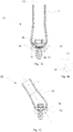
- a screw channel directing device 10 comprises a screw channel part 11 and an implant cooperating part 12.
- the screw channel part 11 comprises a screw channel mouth 13 in the distal end.
- the screw channel part 11 also comprises a screw member seat 14 in the proximal end of the screw channel.
- the screw channel part 11 may be substantially cylindrical with a central axis and a distal screw channel mouth end and a proximal screw member seat end.
- the central axis of the screw channel runs through the center of the screw channel mouth and through the mouth of the screw member seat 14.
- the screw channel part 11 has a circular cross-section along the central axis of the screw channel.
- the circular cross-section may have a first diameter at the proximal end, and then increasing when moving along the longitudinal central axis of the screw channel towards its proximal end.
- the screw channel part 11 is bowl shaped, such that the inner bottom surface has a concave shape and its outer bottom surface 15, i.e. its proximal end, has a convex shape.
- the screw hole of the screw member seat 14 is a long hole. A long hole is a stretched hole.
- the implant cooperating part 12 is a collar comprising an implant seat 16 at its proximal end, and a distal concave screw channel part seat 17.
- the screw channel part seat 17 has a radius corresponding to the radius of the outer proximal end of the screw channel part 11, such that the screw channel part 11 may be tilted angled in relation to the implant onto which the implant cooperating part 12 is arranged.
- the implant seat 16 at the proximal end of the implant cooperating part 12 may be adjusted according to different implant systems available on the market, such that different implant cooperating parts may be used depending on which dental implant is inserted into the jaw bone of the patient.
- a screw member 18 is inserted into the screw channel of the screw channel part 11. Then the screw channel part 11 is loosely screwed into the dental implant through the lumen of the collar of the implant cooperating part 12, with the implant cooperating part 12 distally of the implant but proximally of the screw channel part 11. In this position the screw channel part 11 may be angled/tilted into desired position, by rotating the screw channel part 11 such that the long hole gets into the desired position, i.e. in which the long hole is in the direction of the plane in which the screw channel part 11 is wished to be angled/tilted.
- the long hole of the screw member part 11 may extend from the central axis towards the perimeter of the screw channel part 11, as can be seen in Fig. 1B , which shows the screw channel part 11 from the end which is intended to be positioned towards the working model.
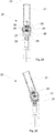
- FIG. 2 a screw channel directing device which does not form part of the invention as claimed is illustrated.
- This screw channel directing device 20 comprises a screw channel part 21 and an implant cooperating part 22.
- the screw channel part 21 comprises a screw channel mouth 23 in the distal end.
- the screw channel part 21 may be substantially cylindrical along the extension of the screw channel, with a central axis and a distal screw channel mouth end and a proximal screw hole 24 with an internal thread.
- the central axis of the screw channel is also the central axis of the screw channel mouth 23.
- the screw channel part 21 has a circular cross-section along the central axis of the screw channel.
- a screw member 25 is arranged in the proximal end of the screw channel of the screw channel part 21 in the proximal end of the screw channel of the screw channel part 21.
- the screw member 25 extends through a screw member seat at the bottom proximal end of the screw channel of the screw channel part 21.
- the screw member 25 has a distal gripping portion 26 adapted for cooperation with a screwing device, such as screw driver, wrench, spanner, etc.
- the screw member has a screw member head 27.
- the screw member head 27 has head configuration in form of a peripheral contour, adapted for cooperation with the implant cooperating part 22 for screwing the implant cooperating part 22 into the dental implant or implant analog, in accordance with below.
- the screw channel part 21 comprises a concave interaction surface 28, for cooperation with the implant cooperating part 22.
- the screw member 25 has a right handed threaded part proximally of the gripping portion. This right handed threaded part may be used to screw the screw member distally, by rotating the distal gripping portion in a right handed way, to secure the implant cooperating part 22 to the dental implant or implant analog.
- the screw member 25 comprises two thread portions proximally of the distal gripping portion, in form of a distal thread portion and a proximal thread portion.
- the distal screw portion is right-handed threaded while the proximal thread portion is left-handed threaded.
- the screw member head 27 is then attached to the screw member 25 via the proximal left-handed thread.
- the screw member head 27 may be screwingly separated from the screw member 25, by rotating the gripping portion 26 in a left-handed way, once the screw member head is in a bottom position, i.e.
- the implant cooperating part 22 has a proximal pin 28 with a threaded part, with an external thread, suitable for securing the implant cooperating part 22 to a dental implant.
- a dental implant seat cooperating part may be arranged at the distal end of the pin 28, by arranging a flange 29 circumferentially of the implant seat, said flange having an inner contour corresponding to the dental implant seat at the distal end of the dental implant.
- the implant cooperating part 22 has an inner gripping cavity in its distal end, said cavity corresponding in shape to the proximal screw member head of the screw member, such that the implant cooperating part 22 may be screwingly secured to the dental implant by screwing the implant cooperating part 22 into the dental implant with by rotating the screw member when the screw member head is in engaged cooperation with the distal inner gripping cavity of the implant cooperating part 22.
- the implant cooperating part 22 has an outer convex shape, forming a convex interaction surface for cooperation with the screw channel part 21.
- the convex interaction surface is adapted to cooperate with the proximal concave proximal concave interaction surface of the screw channel part 21, such that the cooperation works as a ball joint, whereby the screw channel part 21 may be angled/tilted into the desired position.
- the screw member head 27 is adapted to be inserted into the bottom of the cavity with the corresponding shape in the distal end of the implant cooperating part 22 when the screw channel part 21 is arranged in perfect alignment with the implant cooperating part 22, i.e. when the central axis of the screw channel part 21 coincides with the central axis of the implant cooperating part.
- the screw member head 27 can no longer be separated from the implant cooperating part 22.
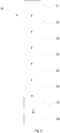
- a method 30 for producing a cast dental superstructure is provided.
- the cast dental superstructure is manufactured by the aid of an angled distance, by means of screw channel directing devices according to above.
- the screw channel directing device is used to obtain an angled screw channel in the cast dental superstructure, whereby the angle between a central axis of a screw channel mouth and the central axis of the dental implant, osseointegrated in the jaw of a subject, may be increased, in comparison with cast superstructures with bent screw channels according to the prior art.
- the screw channel of the screw channel directing device has substantially one central axis extending through the hollow cylinder screw channel.
- the screw channel directing device is tiltable due to a screw channel part and an implant cooperating part which are described above.
- the screw channel part may be meltable in the casting temperature, such that the screw channel part disintegrates during casting.
- the screw channel part may be made of a plastics or wax.
- a dental imprint is made 31 from a subject according to methods known to a person skilled in the art. From the imprint a model of the subjects dental situation is manufactured, according to methods known to the person skilled in the art. In the obtained model of the subjects dental situation an implant analog is mounted 32.
- a screw channel directing device is attached 33 on the analog in the working model, with a laboratory screw.
- the angle of the screw channel directing device is adjusted by tilting 34 the screw channel part in relation to an implant cooperation part, comprised in the screw channel directing device.
- the laboratory screw is fastened to finally secure 35 the screw channel part of the screw channel directing device to the working model in a desired angle.
- the angled screw channel in contrast to the bent screw channel according to prior art cast superstructures, also improves access to the screw channel.
- a superstructure master is made 36 from wax or another meltable material.
- a superstructure master has been obtained with an angled screw channel, wherein the angle has been optimally adapted in relation to the dental situation of the subject.
- the master superstructure is dissembled by removing the laboratory screw, if the screw channel directing device according to Fig. 1 is used.
- the screw channel directing device according to Fig. 2 is used and the master superstructure is dissembled by loosening the threaded pin of the implant cooperating part 22 from the implant analog.
- the master superstructure may then be separated from the screw channel directing device by gently extracting the screw channel directing devices from the master superstructure.
- the master superstructure is scanned when being positioned on the screw channel directing device 10, for subsequent CAD/CAM shaping, such as milling and sintering.
- the master superstructure is embedded in a cuvette with an embedding paste, specific for the material which ultimately will be used to cast the distance, which is appreciated by a person skilled in the art.
- the cavity obtained when extracting the screw channel directing device or the screw channel of the screw channel directing device is also filled with embedding paste.
- the screw channel part o the screw channel directing device is of a material that melts during the casting procedure, in accordance with above, the molt in the subsequent casting will replace the screw channel part.
- the cuvette is pre-heated according to the instructions specific for the embedding paste, which will make both the master superstructure and screw channel directing device melt, in those instances a screw channel directing device is made of a material that melts during this preheating, and the embedding paste hardens, forming 37 a mould.
- the mold represents the geometrical inverse of a tubular, angular geometrical figure, i.e. the desired shape of the superstructure with angled screw channel.
- the superstructure with angled screw channel is then cast 38 in a metal of choice, such as Titanium or Cobalt/Chromium alloy well known to a person skilled in the art, according to the recommendations of the manufacturer of the material.
- a metal of choice such as Titanium or Cobalt/Chromium alloy well known to a person skilled in the art, according to the recommendations of the manufacturer of the material.
- the cast superstructure with angled screw channel may be blasted to create a smooth surface, preferably with aluminum oxide particles with a size between 110 and 250 ⁇ m.
- the metal surfaces which are intended to interact with an analog/fixture, can be adjusted with a reamer.
- the other surfaces may be adjusted by means of a hard metal cutter.
- the superstructure with angled screw channel is then ready to be fitted to the subject.
- the dental facing of the superstructure may be added according to methods known to a person skilled in the art.
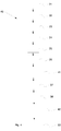
- a method 40 for producing a superstructure with angled screw channel, by means of a screw channel directing device with oversized screw channel part is provided.
- the screw channel directing device is tiltable due to a screw channel part and an implant cooperating part, according to above.
- the oversized screw channel part is larger than a subsequently used screw channel part, for reasons which will be apparent below.
- the first steps of the method 40 are analogous to the previously described method 30.
- a dental imprint is made 31 from a subject according to methods known to a person skilled in the art.
- An implant analog is mounted 32 in the imprint and a working model is made from plaster.
- An oversized screw channel part is attached 33 on the working model by means of the implant cooperation part, with a laboratory screw.
- the angle of the screw channel directing device is adjusted by tilting 34 the screw channel part in relation to the implant cooperation part before the laboratory screw is fastened to finally secure 35 the tiltable, oversized distance model part to the working model, in a desired angle.
- the distance model is wax isolated to create a smooth surface.
- a master superstructure is made 36 from a meltable material, such as the plastic or wax as described above.
- a pre-casting is made.
- the master superstructure is removed 41 from the oversized screw channel part in an occlusional direction, after the master superstructure has been detached from the implant analog(s).
- the master superstructure is then embedded in a cuvette with an embedding paste, specific for the material which ultimately will be used to cast the distance as is appreciated by a person skilled in the art.
- the cuvette is pre-heated according to the instructions specific for the embedding paste, which will make the construct melt and the embedding paste harden, forming 37 a mould.
- a superstructure is cast 38 in the mould with the metal of choice, such as Titanium or Cobalt/Chromium alloy well known to a person skilled in the art, according to the recommendations of the manufacturer.
- the cast superstructure with angled screw channel is blasted to create a smooth surface, preferably with aluminum oxide particles with a size between 110 and 250 ⁇ m.
- the metal surfaces which are intended to interact with an analog/fixture can be adjusted with a reamer.
- the other surfaces may be adjusted by means of a hard metal cutter.
- a screw channel directing device 11 is then inserted into the cavities formed by the oversized screw channel parts.
- the size of the screw channel directing device 11, is thus adapted to fit in the formed/cast cavity.
- the superstructure is then fastened to a working model by laboratory screw(s).
- the screw channel directing device are then fixed to the master superstructure 42, such as welded, glued or soldered, together. This may be done by first welding/gluing/soldering the screw channel directing device to the cast superstructure occlusionally and then at the position of the implant cooperating part, thus forming a superstructure with angled screw channel(s).
- the screw channel directing device is cut 43 to fit with the cast superstructure, so that no part extends outside the edges of the superstructure occlusally.
- the superstructure is then ready to be fitted to the subject.
- the dental facing of the superstructure may be added according to methods known to a person skilled in the art.
- the screw channel part 11 may be made of a material that melts during production of the angled distance which the model is designed to precede.
- meltable materials are plastic or wax.
- the screw channel part 11, of the screw channel directing device 10, may alternately be made from a metal, such as Titanium or a Cobalt/Chromium alloy.
Landscapes
- Health & Medical Sciences (AREA)
- Animal Behavior & Ethology (AREA)
- Dentistry (AREA)
- Epidemiology (AREA)
- Life Sciences & Earth Sciences (AREA)
- Oral & Maxillofacial Surgery (AREA)
- General Health & Medical Sciences (AREA)
- Public Health (AREA)
- Veterinary Medicine (AREA)
- Orthopedic Medicine & Surgery (AREA)
- Engineering & Computer Science (AREA)
- Ceramic Engineering (AREA)
- Dental Prosthetics (AREA)
- Dental Tools And Instruments Or Auxiliary Dental Instruments (AREA)
Description
- The present invention relates to methods for manufacturing of dental superstructures for attachment to dental implants or dental abutments. More specifically, the present invention relates to methods for manufacturing such dental superstructures through casting or CAD/CAM milling/sintering with angled screw channels for screw retaining said superstructure to the dental implant or dental abutment.
- When securing a dental prosthesis to the jaw of a patient, it is commonly known to attach a superstructure to osseointegrated dental implants. However, since the position and angle of the dental implants vary greatly from patient to patient, the use of angled distances is common. These distances are placed upon the dental implant, and the superstructure is then most often cemented to the distances, since it is difficult to screw retain the superstructure to such distances. However, when using separate distances, these will inevitably extend - at least to some extent - in the axial direction of the dental implant. It is then often very difficult or even impossible to apply the superstructure on such distances, since the application of the superstructure calls for a substantially parallel arrangement of the distances. Also, the mounting process when using such distances is very complicated and cumbersome, since a vast number of different distances must be tested on the implants, to find the needed match. Also, interfaces between the distances and the superstructure are hygienically bad.
- In order to model the desired position of the screw channel mouth in screw retained superstructures, it is known to position acrylic tubes on a model of the jaw of a subject. The model shows the position of the osseointegrated dental implants, and the acrylic tubes are placed at these positions and bent to the desired curvature before a mould is formed, based on the bent acrylic tubes. Subsequently, separate seat support cylinders are planarized together with the casted superstructure, whereafter the separate screw member seat support cylinders are welded onto the casted superstructure.
- However, it may be hard to bend the acrylic tubes correctly. Bending the tubes to the desired curvature is tedious and the tubes may flex after bending, which may result in a mould with erroneous angles. Furthermore, it is only possible to obtain bent screw channels, following a curvature, whereby the angle between the central axis of the mouth of the attached screw seat and the central axis of the screw channel mouth is limited to angles less than 17 degrees. Also, the manufacturing procedure is quite cumbersome, including several separate manufacturing steps, such as casting, planarization, fitting, welding etc.
- Thus, there is a need for a new method and device, allowing for improved construction of angled distances
- The document
EP 0 313 222 discloses a method for manufacturing a dental superstructure or part thereof, comprising the steps of (i) making a dental imprint from the mouth of a subject; (ii) manufacturing a working model from said dental imprint and mounting an implant analog in the working model; (iii) attaching a screw channel directing device, comprising a screw channel part and an implant cooperating part, said screw channel part comprising a screw channel mouth in the distal end, and a screw member seat with a screw hole in the proximal end, wherein the proximal end of the screw channel part is bowl shaped, such that the inner bottom surface has a concave shape and its outer bottom surface has a convex shape, and wherein the screw hole of the screw member seat is larger than the the dimension of the screw, and wherein said implant cooperating part is collar-shaped with an implant seat at its proximal end, and a distal concave screw channel part seat, wherein the screw channel part seat has a radius corresponding to the radius of the outer bottom surface of the screw channel part to form a ball joint, such that the central axis of the screw channel part may be tilted/angled in relation to a central axis of the implant cooperating part, to the implant analog in the working model ; (iv) tilting the screw channel part in relation to the implant cooperating part into a desired angle; (v) shaping a master superstructure or part thereof onto the screw channel directing device; (vi) casting of the dental superstructure by using the lost wax technique. - Document
DE 199 59 366 A1 discloses a similar method. - Accordingly, the present invention preferably seeks to mitigate, alleviate or eliminate one or more of the above-identified deficiencies in the art and disadvantages singly or in any combination and solves at least the above mentioned problems by providing a method for manufacturing a dental superstructure or part thereof, comprising the steps of (i) making a dental imprint from the mouth of a subject; (ii) mounting an analog in the imprint to obtain a working model; (iii) attaching a screw channel directing device, comprising a screw channel part and an implant cooperating part, said screw channel part being tiltable in relation to the implant cooperating part, to the working model; (iv) tilting the screw channel part in relation to the implant cooperating part into a desired angle; (v) shaping a mold creating a master superstructure or part thereof onto the screw channel directing device; (vi) forming a mold based on the master superstructure or part thereof; and (vii) casting or CAD/CAM shaping of the dental superstructure or part thereof;
a screw channel directing device, comprising a screw channel part and an implant cooperating part, said screw channel part comprising a screw channel mouth in the distal end, and a screw member seat with a screw hole in the proximal end, wherein the proximal end of the screw channel part is bowl shaped, such that the inner bottom surface has a concave shape and its outer bottom surface has a convex shape, and wherein the screw hole of the screw member seat is a long hole, and wherein said implant cooperating part is collar-shaped with an implant seat at its proximal end, and a distal concave screw channel part seat, wherein the screw channel part seat has a radius corresponding to the radius of the outer bottom surface of the screw channel part to form a ball joint, such that the central axis of the screw channel part may be tilted/angled in relation to a central axis of the implant cooperating part. - These and other aspects, features and advantages of which the invention is capable of will be apparent and elucidated from the following description of embodiments of the present invention, reference being made to the accompanying drawings, in which
-
Fig. 1 is a schematic cross-section of a tiltable screw channel directing device for use according to an embodiment; and -
Fig. 2 is a schematic cross-section of a tiltable screw channel directing device which is not covered by the appended claims. -
Fig. 3 is a flowchart showing the steps of a method according to an embodiment; and -
Fig. 4 is a flowchart showing the steps of a method according to another embodiment - Several embodiments of the present invention will be described in more detail below with reference to the accompanying drawings in order for those skilled in the art to be able to carry out the invention. The invention may, however, be embodied in many different forms and should not be construed as limited to the embodiments set forth herein. Rather, these embodiments are provided so that this disclosure will be thorough and complete, and will fully convey the scope of the invention to those skilled in the art. The embodiments do not limit the invention, but the invention is only limited by the appended patent claims. Furthermore, the terminology used in the detailed description of the particular embodiments illustrated in the accompanying drawings is not intended to be limiting of the invention.
- Embodiments of the present invention relate to methods for producing a cast dental superstructure, with improved angling possibilities and facilitated manufacturing. The embodiments are realized by the aid of an angled distance in form of a screw channel directing device. The screw channel directing device is used to obtain an angled screw channel in the cast dental superstructure, whereby the angle between a central axis of a screw channel mouth and the central axis of the dental implant, osseointegrated in the jaw of a subject, may be increased, in comparison with cast superstructures with bent screw channels according to the prior art.
- In
Fig. 1 , a screw channel directing device 10 is provided. The screw channel directing device 10 comprises ascrew channel part 11 and animplant cooperating part 12. Thescrew channel part 11 comprises ascrew channel mouth 13 in the distal end. Thescrew channel part 11 also comprises ascrew member seat 14 in the proximal end of the screw channel. Thescrew channel part 11 may be substantially cylindrical with a central axis and a distal screw channel mouth end and a proximal screw member seat end. The central axis of the screw channel runs through the center of the screw channel mouth and through the mouth of thescrew member seat 14. Preferably, thescrew channel part 11 has a circular cross-section along the central axis of the screw channel. The circular cross-section may have a first diameter at the proximal end, and then increasing when moving along the longitudinal central axis of the screw channel towards its proximal end. In the proximal end, thescrew channel part 11 is bowl shaped, such that the inner bottom surface has a concave shape and itsouter bottom surface 15, i.e. its proximal end, has a convex shape. The screw hole of thescrew member seat 14 is a long hole. A long hole is a stretched hole. - The
implant cooperating part 12 is a collar comprising animplant seat 16 at its proximal end, and a distal concave screwchannel part seat 17. The screwchannel part seat 17 has a radius corresponding to the radius of the outer proximal end of thescrew channel part 11, such that thescrew channel part 11 may be tilted angled in relation to the implant onto which theimplant cooperating part 12 is arranged. Theimplant seat 16 at the proximal end of theimplant cooperating part 12 may be adjusted according to different implant systems available on the market, such that different implant cooperating parts may be used depending on which dental implant is inserted into the jaw bone of the patient. - When angling/tilting the
screw channel part 11 on theimplant cooperating part 12, ascrew member 18 is inserted into the screw channel of thescrew channel part 11. Then thescrew channel part 11 is loosely screwed into the dental implant through the lumen of the collar of theimplant cooperating part 12, with theimplant cooperating part 12 distally of the implant but proximally of thescrew channel part 11. In this position thescrew channel part 11 may be angled/tilted into desired position, by rotating thescrew channel part 11 such that the long hole gets into the desired position, i.e. in which the long hole is in the direction of the plane in which thescrew channel part 11 is wished to be angled/tilted. The long hole of thescrew member part 11 may extend from the central axis towards the perimeter of thescrew channel part 11, as can be seen inFig. 1B , which shows thescrew channel part 11 from the end which is intended to be positioned towards the working model. Thus, by sliding thescrew channel part 11 in the concave screwchannel part seat 17 of theimplant cooperating part 12 along the extension of the long hole, when theimplant cooperating part 12 is attached to the model, via the implant analog, but not yet fully secured, it is possible to tilt the hollowscrew channel part 11 in relation to the model, as can be seen inFig. 1C . - In
Fig. 2 a screw channel directing device which does not form part of the invention as claimed is illustrated. This screw channel directingdevice 20 comprises ascrew channel part 21 and animplant cooperating part 22. Thescrew channel part 21 comprises ascrew channel mouth 23 in the distal end. Thescrew channel part 21 may be substantially cylindrical along the extension of the screw channel, with a central axis and a distal screw channel mouth end and aproximal screw hole 24 with an internal thread. The central axis of the screw channel is also the central axis of thescrew channel mouth 23. Preferably, thescrew channel part 21 has a circular cross-section along the central axis of the screw channel. - In the proximal end of the screw channel of the screw channel part 21 a
screw member 25 is arranged. Thescrew member 25 extends through a screw member seat at the bottom proximal end of the screw channel of thescrew channel part 21. Thescrew member 25 has a distal grippingportion 26 adapted for cooperation with a screwing device, such as screw driver, wrench, spanner, etc. In the proximal end the screw member has ascrew member head 27. Thescrew member head 27 has head configuration in form of a peripheral contour, adapted for cooperation with theimplant cooperating part 22 for screwing theimplant cooperating part 22 into the dental implant or implant analog, in accordance with below. Proximally of the screw member seat, thescrew channel part 21 comprises aconcave interaction surface 28, for cooperation with theimplant cooperating part 22. - In one alternative, the
screw member 25 has a right handed threaded part proximally of the gripping portion. This right handed threaded part may be used to screw the screw member distally, by rotating the distal gripping portion in a right handed way, to secure theimplant cooperating part 22 to the dental implant or implant analog. - In another alternative, the
screw member 25 comprises two thread portions proximally of the distal gripping portion, in form of a distal thread portion and a proximal thread portion. Preferably, the distal screw portion is right-handed threaded while the proximal thread portion is left-handed threaded. Thescrew member head 27 is then attached to thescrew member 25 via the proximal left-handed thread. When thescrew member head 27 is connected to thescrew member 25 via a left-handed thread, thescrew member head 27 may be screwingly separated from thescrew member 25, by rotating the grippingportion 26 in a left-handed way, once the screw member head is in a bottom position, i.e. either in bottom cooperation with theimplant cooperation part 22 or when theimplant cooperating part 22 and thescrew channel part 21 are pressed against each other, in accordance with below. This brings about the technical effects of enabling separation of thescrew channel part 21 and theimplant cooperating part 22 when thescrew channel part 21 is secured, such as welded, cast, or solded to the superstructure. - The
implant cooperating part 22 has aproximal pin 28 with a threaded part, with an external thread, suitable for securing theimplant cooperating part 22 to a dental implant. A dental implant seat cooperating part may be arranged at the distal end of thepin 28, by arranging aflange 29 circumferentially of the implant seat, said flange having an inner contour corresponding to the dental implant seat at the distal end of the dental implant. In accordance with above, different implant systems available on the market with differing implant seats, such that differentimplant cooperating parts 22 may be used depending on which dental implant is inserted into the jaw bone of the patient. - The
implant cooperating part 22 has an inner gripping cavity in its distal end, said cavity corresponding in shape to the proximal screw member head of the screw member, such that theimplant cooperating part 22 may be screwingly secured to the dental implant by screwing theimplant cooperating part 22 into the dental implant with by rotating the screw member when the screw member head is in engaged cooperation with the distal inner gripping cavity of theimplant cooperating part 22. - The
implant cooperating part 22 has an outer convex shape, forming a convex interaction surface for cooperation with thescrew channel part 21. The convex interaction surface is adapted to cooperate with the proximal concave proximal concave interaction surface of thescrew channel part 21, such that the cooperation works as a ball joint, whereby thescrew channel part 21 may be angled/tilted into the desired position. - The
screw member head 27 is adapted to be inserted into the bottom of the cavity with the corresponding shape in the distal end of theimplant cooperating part 22 when thescrew channel part 21 is arranged in perfect alignment with theimplant cooperating part 22, i.e. when the central axis of thescrew channel part 21 coincides with the central axis of the implant cooperating part. When then the central axis of thescrew channel part 21 is angled in relation to the central axis of theimplant cooperating part 22, thescrew member head 27 can no longer be separated from theimplant cooperating part 22. This can be accomplished by having a slanting contact surface on the distal end of thescrew member head 27, such as for example semi-spherical or spherical shape, and a corresponding negative slanting surface in the cavity of theimplant cooperating part 22. In this way thescrew member head 27 may be screwed distally to secure thescrew channel part 21 to theimplant cooperating part 22. - In an embodiment, according to the flow chart in
Fig. 3 , amethod 30 for producing a cast dental superstructure is provided. The cast dental superstructure is manufactured by the aid of an angled distance, by means of screw channel directing devices according to above. The screw channel directing device is used to obtain an angled screw channel in the cast dental superstructure, whereby the angle between a central axis of a screw channel mouth and the central axis of the dental implant, osseointegrated in the jaw of a subject, may be increased, in comparison with cast superstructures with bent screw channels according to the prior art. Thus, the screw channel of the screw channel directing device has substantially one central axis extending through the hollow cylinder screw channel. - The screw channel directing device is tiltable due to a screw channel part and an implant cooperating part which are described above.
- In one embodiment the screw channel part may be meltable in the casting temperature, such that the screw channel part disintegrates during casting. In these instances the screw channel part may be made of a plastics or wax.
- A dental imprint is made 31 from a subject according to methods known to a person skilled in the art. From the imprint a model of the subjects dental situation is manufactured, according to methods known to the person skilled in the art. In the obtained model of the subjects dental situation an implant analog is mounted 32.
- Then, a screw channel directing device, according to below, is attached 33 on the analog in the working model, with a laboratory screw. The angle of the screw channel directing device is adjusted by tilting 34 the screw channel part in relation to an implant cooperation part, comprised in the screw channel directing device. Then the laboratory screw is fastened to finally secure 35 the screw channel part of the screw channel directing device to the working model in a desired angle.
- This is advantageous, since it is possible to achieve angles larger than 17 degrees, such as between 18 and 25, which is desirable since it allows for greater freedom in screw channel mouth placement on the superstructure. The angled screw channel, in contrast to the bent screw channel according to prior art cast superstructures, also improves access to the screw channel.
- On top of the distance model, a superstructure master is made 36 from wax or another meltable material. Thus, a superstructure master has been obtained with an angled screw channel, wherein the angle has been optimally adapted in relation to the dental situation of the subject.
- Thereafter, the master superstructure is dissembled by removing the laboratory screw, if the screw channel directing device according to
Fig. 1 is used. In a method which is not covered by the appended claims,the screw channel directing device according toFig. 2 is used and the master superstructure is dissembled by loosening the threaded pin of theimplant cooperating part 22 from the implant analog. The master superstructure may then be separated from the screw channel directing device by gently extracting the screw channel directing devices from the master superstructure. - It is also possible to leave the screw channel directing device in the master supertstructure.
- In yet another embodiment, the master superstructure is scanned when being positioned on the screw channel directing device 10, for subsequent CAD/CAM shaping, such as milling and sintering.
- Then, the master superstructure is embedded in a cuvette with an embedding paste, specific for the material which ultimately will be used to cast the distance, which is appreciated by a person skilled in the art.
- The cavity obtained when extracting the screw channel directing device or the screw channel of the screw channel directing device is also filled with embedding paste. In those instances in which the screw channel part o the screw channel directing device is of a material that melts during the casting procedure, in accordance with above, the molt in the subsequent casting will replace the screw channel part.
- The cuvette is pre-heated according to the instructions specific for the embedding paste, which will make both the master superstructure and screw channel directing device melt, in those instances a screw channel directing device is made of a material that melts during this preheating, and the embedding paste hardens, forming 37 a mould.
- Since the cavity of the screw channel directing device was also filled with embedding paste, the mold represents the geometrical inverse of a tubular, angular geometrical figure, i.e. the desired shape of the superstructure with angled screw channel.
- The superstructure with angled screw channel is then cast 38 in a metal of choice, such as Titanium or Cobalt/Chromium alloy well known to a person skilled in the art, according to the recommendations of the manufacturer of the material. After cooling, the cast superstructure with angled screw channel may be blasted to create a smooth surface, preferably with aluminum oxide particles with a size between 110 and 250 µm.
- Optionally, the metal surfaces, which are intended to interact with an analog/fixture, can be adjusted with a reamer. The other surfaces may be adjusted by means of a hard metal cutter.
- The superstructure with angled screw channel is then ready to be fitted to the subject. The dental facing of the superstructure may be added according to methods known to a person skilled in the art.
- In another embodiment according to
Fig. 4 , amethod 40 for producing a superstructure with angled screw channel, by means of a screw channel directing device with oversized screw channel part is provided. - The screw channel directing device is tiltable due to a screw channel part and an implant cooperating part, according to above.
- The oversized screw channel part is larger than a subsequently used screw channel part, for reasons which will be apparent below.
- The first steps of the
method 40 are analogous to the previously describedmethod 30. - A dental imprint is made 31 from a subject according to methods known to a person skilled in the art. An implant analog is mounted 32 in the imprint and a working model is made from plaster. An oversized screw channel part is attached 33 on the working model by means of the implant cooperation part, with a laboratory screw.
- The angle of the screw channel directing device is adjusted by tilting 34 the screw channel part in relation to the implant cooperation part before the laboratory screw is fastened to finally secure 35 the tiltable, oversized distance model part to the working model, in a desired angle.
- Optionally, the distance model is wax isolated to create a smooth surface.
- On top of the distance model, a master superstructure is made 36 from a meltable material, such as the plastic or wax as described above.
- Optionally, a pre-casting is made.
- The master superstructure is removed 41 from the oversized screw channel part in an occlusional direction, after the master superstructure has been detached from the implant analog(s).
- The master superstructure is then embedded in a cuvette with an embedding paste, specific for the material which ultimately will be used to cast the distance as is appreciated by a person skilled in the art.
- The cuvette is pre-heated according to the instructions specific for the embedding paste, which will make the construct melt and the embedding paste harden, forming 37 a mould.
- A superstructure is cast 38 in the mould with the metal of choice, such as Titanium or Cobalt/Chromium alloy well known to a person skilled in the art, according to the recommendations of the manufacturer. The cast superstructure with angled screw channel is blasted to create a smooth surface, preferably with aluminum oxide particles with a size between 110 and 250 µm.
- Optionally, the metal surfaces which are intended to interact with an analog/fixture can be adjusted with a reamer. The other surfaces may be adjusted by means of a hard metal cutter.
- A screw
channel directing device 11, is then inserted into the cavities formed by the oversized screw channel parts. The size of the screwchannel directing device 11, is thus adapted to fit in the formed/cast cavity. The superstructure is then fastened to a working model by laboratory screw(s). - The screw channel directing device are then fixed to the
master superstructure 42, such as welded, glued or soldered, together. This may be done by first welding/gluing/soldering the screw channel directing device to the cast superstructure occlusionally and then at the position of the implant cooperating part, thus forming a superstructure with angled screw channel(s). - Next, the screw channel directing device is cut 43 to fit with the cast superstructure, so that no part extends outside the edges of the superstructure occlusally. The superstructure is then ready to be fitted to the subject. The dental facing of the superstructure may be added according to methods known to a person skilled in the art.
- The
screw channel part 11, may be made of a material that melts during production of the angled distance which the model is designed to precede. Examples of meltable materials are plastic or wax. - The
screw channel part 11, of the screw channel directing device 10, may alternately be made from a metal, such as Titanium or a Cobalt/Chromium alloy. - Although the present invention has been described above with reference to specific embodiments, it is not intended to be limited to the specific form set forth herein. Rather, the invention is limited only by the accompanying claims and, other embodiments than the specific above are equally possible within the scope of these appended claims.
- In the claims, the term "comprises/comprising" does not exclude the presence of other elements or steps. Furthermore, although individually listed, a plurality of means, elements or method steps may be implemented by e.g. a single unit or processor. Additionally, although individual features may be included in different claims, these may possibly advantageously be combined, and the inclusion in different claims does not imply that a combination of features is not feasible and/or advantageous. In addition, singular references do not exclude a plurality. The terms "a", "an", "first", "second" etc do not preclude a plurality. Reference signs in the claims are provided merely as a clarifying example and shall not be construed as limiting the scope of the claims in any way.
Claims (4)
- A method (30) for manufacturing a dental superstructure or part thereof, comprising the steps of(i) making (31) a dental imprint from the mouth of a subject;(ii) manufacturing a working model from said dental imprint and mounting (32) an implant analog in the working model;(iii) attaching (33) a screw channel directing device (10), comprising a screw channel part (11) and an implant cooperating part (12), said screw channel part (11) comprising a screw channel mouth (13) in the distal end, and a screw member seat (14) with a screw hole in the proximal end, wherein the proximal end of the screw channel part (11) is bowl shaped, such that the inner bottom surface has a concave shape and its outer bottom surface (15) has a convex shape, and wherein the screw hole of the screw member seat (14) is a long hole, and wherein said implant cooperating part (12) is collar-shaped with an implant seat (16) at its proximal end, and a distal concave screw channel part seat (17), wherein the screw channel part seat (17) has a radius corresponding to the radius of the outer bottom surface (15) of the screw channel part (11) to form a ball joint, such that the central axis of the screw channel part (11) may be tilted/angled in relation to a central axis of the implant cooperating part (12), to the implant analog in the working model;(iv) tilting (34) the screw channel part (11) in relation to the implant cooperating part (12) into a desired angle;(v) shaping a master superstructure or part thereof onto the screw channel directing device (10);(vi) forming (37) a mold based on the master superstructure or part thereof; and (vii) casting (38) or CAD/CAM shaping of the dental superstructure or part thereof.
- The method according to claim 1, wherein step (vii) is casting (38), and further comprising the step of(viii) removing the screw channel directing device (10) from the master superstructure between step (v) and step (vi), where a screw channel part of the screw channel directing device (10) is oversized;(ix) inserting (42) a second screw channel directing device (10) in the cast dental superstructure after step (vii), corresponding to the shape of the cavity formed in step (v) by the oversized screw channel part of the screw channel directing device (10) ; and(x) attaching the second screw channel directing device (10) inserted in the cast dental superstructure in step (ix) by welding, gluing, or soldering.
- The method according to claim 1, wherein screw channel directing device (10) or the screw channel part (11) thereof is melted during step (vii).
- The method according to claim 1, wherein screw channel directing device (10) or the screw channel part (11) thereof is a metal screw channel directing device (10) or metal screw channel part (11), which is adhered to the superstructure during step (vii).
Applications Claiming Priority (2)
| Application Number | Priority Date | Filing Date | Title |
|---|---|---|---|
| SE1150443 | 2011-05-16 | ||
| PCT/EP2012/059152 WO2012156458A2 (en) | 2011-05-16 | 2012-05-16 | Superstructure and methods for manufacturing the same |
Publications (2)
| Publication Number | Publication Date |
|---|---|
| EP2709552A2 EP2709552A2 (en) | 2014-03-26 |
| EP2709552B1 true EP2709552B1 (en) | 2019-09-04 |
Family
ID=46125450
Family Applications (1)
| Application Number | Title | Priority Date | Filing Date |
|---|---|---|---|
| EP12722145.5A Active EP2709552B1 (en) | 2011-05-16 | 2012-05-16 | Dental superstructure and method for manufacturing the same |
Country Status (10)
| Country | Link |
|---|---|
| US (1) | US9554878B2 (en) |
| EP (1) | EP2709552B1 (en) |
| JP (1) | JP2014515956A (en) |
| KR (1) | KR101570279B1 (en) |
| CN (1) | CN103582465B (en) |
| AU (1) | AU2012258257B2 (en) |
| BR (1) | BR112013029518A2 (en) |
| CA (1) | CA2834659C (en) |
| IL (1) | IL229262A0 (en) |
| WO (1) | WO2012156458A2 (en) |
Families Citing this family (10)
| Publication number | Priority date | Publication date | Assignee | Title |
|---|---|---|---|---|
| KR200471489Y1 (en) * | 2012-04-04 | 2014-02-28 | 왕제원 | Freely adjust the angle and position adjustable attachment for fixing dentures |
| US9687320B2 (en) | 2014-02-17 | 2017-06-27 | Sterngold Dental, Llc | Dental device for anchoring a denture to an implant |
| HU230869B1 (en) | 2014-10-14 | 2018-10-29 | Edvin Elsner | Screw channel insert |
| KR20180019643A (en) * | 2015-06-19 | 2018-02-26 | 노벨 바이오케어 서비시스 아게 | Method for producing a tooth connecting assembly and a dental prosthesis |
| EP3335666B1 (en) | 2016-12-15 | 2021-03-10 | Ivoclar Vivadent AG | Device for holding an arrangement made of a superstructure and abutment |
| WO2018184119A1 (en) * | 2017-04-07 | 2018-10-11 | Panthera Dental Inc. | Drop-shaped screw conduit for a dental superstructure and designing method thereof |
| KR101869348B1 (en) * | 2017-07-04 | 2018-06-20 | (주) 코웰메디 | Method for manufacturing an implant fixture and implant fixture |
| LU100935B1 (en) * | 2018-09-19 | 2020-03-19 | Jade Finance S A R L | Improved blank for production of a dental prosthesis, a dental prosthesis and method of manufacturing same |
| US12303352B2 (en) | 2021-06-03 | 2025-05-20 | Full Arch Solutions, Llc | Omni-directional multi-unit abutment dental systems |
| JP7630017B2 (en) | 2021-06-03 | 2025-02-14 | フル アーチ ソリューションズ, エルエルシー | Omnidirectional multi-unit abutment system for screw-mounted dental prostheses |
Citations (5)
| Publication number | Priority date | Publication date | Assignee | Title |
|---|---|---|---|---|
| EP0313222A2 (en) * | 1987-09-24 | 1989-04-26 | Steven Gorgas Detsch | Dental implant attachment system |
| EP0580945A1 (en) * | 1992-07-27 | 1994-02-02 | ALTATEC Medizintechnische Elemente GmbH & Co. KG. | Endo-osseous tooth implant for a fixed dental prosthesis and a fixing tool |
| DE19959366A1 (en) * | 1999-12-09 | 2001-06-13 | Stefan Wintermantel | Implant structure for enossal (in-bone) tooth implant is connectable to implant by screw and comprises post together with connecting part applicable to implant basal to post |
| WO2001047429A1 (en) * | 1999-12-24 | 2001-07-05 | Unger Heinz Dieter | Implant body |
| EP1810641A1 (en) * | 2004-07-30 | 2007-07-25 | Esteban Xam-Mar Mangrane | Dynamic pier for correcting incorrectly-positioned implants and corresponding tool |
Family Cites Families (13)
| Publication number | Priority date | Publication date | Assignee | Title |
|---|---|---|---|---|
| SE328961B (en) * | 1970-03-25 | 1970-09-28 | Aga Ab | |
| DE3531389A1 (en) * | 1985-09-03 | 1987-03-05 | Kirsch Axel | ENOSSAL IMPLANT |
| US4832601A (en) | 1987-12-04 | 1989-05-23 | Hall Surgical | Adjustable support for a prosthetic tooth and method |
| US4907969A (en) * | 1988-04-14 | 1990-03-13 | Ward Whitley S | Universal dental prosthesis retention system |
| CN2182604Y (en) * | 1994-01-04 | 1994-11-16 | 中国人民解放军第四军医大学口腔医学院 | Upper base for implanting teeth |
| CH694571A5 (en) * | 1999-06-21 | 2005-04-15 | Dcs Forschungs & Entwicklungs | A method for producing a dental prosthesis and a dental prosthesis, material for a dental prosthesis and dental prosthesis. |
| US6358052B1 (en) | 1999-07-15 | 2002-03-19 | L. Paul Lustig | Dental implant system and method for effecting a dental restoration using the same |
| US7887327B2 (en) * | 2001-08-31 | 2011-02-15 | Leonard Marotta | Accurate analogs for prostheses using computer generated anatomical models |
| EP1547543A1 (en) | 2003-12-23 | 2005-06-29 | Steffen Dr. Heitland | Abutment for dental implants |
| US7214063B2 (en) * | 2004-07-29 | 2007-05-08 | Yechiel Cohen | Implant system particularly useful for fixing dental prostheses to bone |
| DE202004016896U1 (en) | 2004-10-29 | 2005-03-17 | Profim Ltd | Prosthetic superstructure with cone |
| WO2009033297A1 (en) | 2007-09-12 | 2009-03-19 | Cendres + Métaux Sa | Arrangement for forming a bridge structure, and fastening screw therefor |
| FR2927796A1 (en) | 2008-02-26 | 2009-08-28 | Gerard Gonzalez | Dental implant for being implanted in upper jaw or mandibula of patient, has insertable piece and implant pillar connected between each other by hinge, and immobilization unit for immobilization of pillar in appropriate position |
-
2012
- 2012-05-16 EP EP12722145.5A patent/EP2709552B1/en active Active
- 2012-05-16 US US14/117,931 patent/US9554878B2/en active Active
- 2012-05-16 AU AU2012258257A patent/AU2012258257B2/en not_active Ceased
- 2012-05-16 CA CA2834659A patent/CA2834659C/en active Active
- 2012-05-16 KR KR1020137031499A patent/KR101570279B1/en active Active
- 2012-05-16 JP JP2014510802A patent/JP2014515956A/en active Pending
- 2012-05-16 BR BR112013029518A patent/BR112013029518A2/en not_active IP Right Cessation
- 2012-05-16 CN CN201280024040.9A patent/CN103582465B/en not_active Expired - Fee Related
- 2012-05-16 WO PCT/EP2012/059152 patent/WO2012156458A2/en not_active Ceased
-
2013
- 2013-11-05 IL IL229262A patent/IL229262A0/en unknown
Patent Citations (5)
| Publication number | Priority date | Publication date | Assignee | Title |
|---|---|---|---|---|
| EP0313222A2 (en) * | 1987-09-24 | 1989-04-26 | Steven Gorgas Detsch | Dental implant attachment system |
| EP0580945A1 (en) * | 1992-07-27 | 1994-02-02 | ALTATEC Medizintechnische Elemente GmbH & Co. KG. | Endo-osseous tooth implant for a fixed dental prosthesis and a fixing tool |
| DE19959366A1 (en) * | 1999-12-09 | 2001-06-13 | Stefan Wintermantel | Implant structure for enossal (in-bone) tooth implant is connectable to implant by screw and comprises post together with connecting part applicable to implant basal to post |
| WO2001047429A1 (en) * | 1999-12-24 | 2001-07-05 | Unger Heinz Dieter | Implant body |
| EP1810641A1 (en) * | 2004-07-30 | 2007-07-25 | Esteban Xam-Mar Mangrane | Dynamic pier for correcting incorrectly-positioned implants and corresponding tool |
Also Published As
| Publication number | Publication date |
|---|---|
| BR112013029518A2 (en) | 2017-01-24 |
| KR20140045365A (en) | 2014-04-16 |
| US20140154643A1 (en) | 2014-06-05 |
| WO2012156458A3 (en) | 2013-03-28 |
| KR101570279B1 (en) | 2015-11-18 |
| AU2012258257B2 (en) | 2015-09-10 |
| WO2012156458A2 (en) | 2012-11-22 |
| EP2709552A2 (en) | 2014-03-26 |
| AU2012258257A1 (en) | 2013-11-07 |
| CA2834659C (en) | 2017-03-21 |
| JP2014515956A (en) | 2014-07-07 |
| CN103582465A (en) | 2014-02-12 |
| CA2834659A1 (en) | 2012-11-22 |
| IL229262A0 (en) | 2014-01-30 |
| US9554878B2 (en) | 2017-01-31 |
| CN103582465B (en) | 2016-08-24 |
Similar Documents
| Publication | Publication Date | Title |
|---|---|---|
| US9333057B2 (en) | Screw channel directing device for a dental superstructure and methods for manufacturing a dental superstructure | |
| EP2709552B1 (en) | Dental superstructure and method for manufacturing the same | |
| US20110171603A1 (en) | Implant abutment material for tailor-made and method for manufacturing abutment using the same | |
| US20050112524A1 (en) | Method for manufacturing a suprastructure and a corresponding drill jig | |
| US20040078040A1 (en) | Fastening device for an orthesis or prosthesis | |
| JP2002528169A (en) | Ceramic dental implant with metal core | |
| US4744756A (en) | Apparatus for forming dental prosthesis | |
| EP3007645A1 (en) | Dental prosthesis and a method for making the prosthesis | |
| US20090202962A1 (en) | Dynamic Pillar for Correcting Incorrectly Positioned Implants and a Toll Therefor | |
| EP1704829B1 (en) | Abutment set for a dental implant and method of manufacturing a dental prosthesis | |
| EP3206623B1 (en) | Screw channel insertion piece | |
| US9072567B2 (en) | Superstructure and methods for manufacturing the same | |
| RU2592782C2 (en) | Denture | |
| JP3652873B2 (en) | Dental magnetic material holder |
Legal Events
| Date | Code | Title | Description |
|---|---|---|---|
| PUAI | Public reference made under article 153(3) epc to a published international application that has entered the european phase |
Free format text: ORIGINAL CODE: 0009012 |
|
| 17P | Request for examination filed |
Effective date: 20131031 |
|
| AK | Designated contracting states |
Kind code of ref document: A2 Designated state(s): AL AT BE BG CH CY CZ DE DK EE ES FI FR GB GR HR HU IE IS IT LI LT LU LV MC MK MT NL NO PL PT RO RS SE SI SK SM TR |
|
| DAX | Request for extension of the european patent (deleted) | ||
| RAP1 | Party data changed (applicant data changed or rights of an application transferred) |
Owner name: HERAEUS KULZER NORDIC AB |
|
| 17Q | First examination report despatched |
Effective date: 20160802 |
|
| RAP1 | Party data changed (applicant data changed or rights of an application transferred) |
Owner name: HERAEUS KULZER GMBH |
|
| STAA | Information on the status of an ep patent application or granted ep patent |
Free format text: STATUS: REQUEST FOR EXAMINATION WAS MADE |
|
| PUAG | Search results despatched under rule 164(2) epc together with communication from examining division |
Free format text: ORIGINAL CODE: 0009017 |
|
| STAA | Information on the status of an ep patent application or granted ep patent |
Free format text: STATUS: EXAMINATION IS IN PROGRESS |
|
| 17Q | First examination report despatched |
Effective date: 20170202 |
|
| B565 | Issuance of search results under rule 164(2) epc |
Effective date: 20170202 |
|
| RAP1 | Party data changed (applicant data changed or rights of an application transferred) |
Owner name: KULZER GMBH |
|
| GRAP | Despatch of communication of intention to grant a patent |
Free format text: ORIGINAL CODE: EPIDOSNIGR1 |
|
| STAA | Information on the status of an ep patent application or granted ep patent |
Free format text: STATUS: GRANT OF PATENT IS INTENDED |
|
| RIC1 | Information provided on ipc code assigned before grant |
Ipc: A61C 13/34 20060101ALI20190226BHEP Ipc: A61C 8/00 20060101AFI20190226BHEP Ipc: A61C 13/00 20060101ALN20190226BHEP |
|
| RIC1 | Information provided on ipc code assigned before grant |
Ipc: A61C 13/00 20060101ALN20190304BHEP Ipc: A61C 8/00 20060101AFI20190304BHEP Ipc: A61C 13/34 20060101ALI20190304BHEP |
|
| INTG | Intention to grant announced |
Effective date: 20190402 |
|
| GRAS | Grant fee paid |
Free format text: ORIGINAL CODE: EPIDOSNIGR3 |
|
| GRAA | (expected) grant |
Free format text: ORIGINAL CODE: 0009210 |
|
| STAA | Information on the status of an ep patent application or granted ep patent |
Free format text: STATUS: THE PATENT HAS BEEN GRANTED |
|
| AK | Designated contracting states |
Kind code of ref document: B1 Designated state(s): AL AT BE BG CH CY CZ DE DK EE ES FI FR GB GR HR HU IE IS IT LI LT LU LV MC MK MT NL NO PL PT RO RS SE SI SK SM TR |
|
| REG | Reference to a national code |
Ref country code: GB Ref legal event code: FG4D |
|
| REG | Reference to a national code |
Ref country code: CH Ref legal event code: EP |
|
| REG | Reference to a national code |
Ref country code: AT Ref legal event code: REF Ref document number: 1174280 Country of ref document: AT Kind code of ref document: T Effective date: 20190915 |
|
| REG | Reference to a national code |
Ref country code: DE Ref legal event code: R096 Ref document number: 602012063606 Country of ref document: DE |
|
| REG | Reference to a national code |
Ref country code: CH Ref legal event code: NV Representative=s name: ISLER AND PEDRAZZINI AG, CH |
|
| REG | Reference to a national code |
Ref country code: IE Ref legal event code: FG4D |
|
| REG | Reference to a national code |
Ref country code: SE Ref legal event code: TRGR |
|
| REG | Reference to a national code |
Ref country code: NL Ref legal event code: MP Effective date: 20190904 |
|
| REG | Reference to a national code |
Ref country code: LT Ref legal event code: MG4D |
|
| PG25 | Lapsed in a contracting state [announced via postgrant information from national office to epo] |
Ref country code: HR Free format text: LAPSE BECAUSE OF FAILURE TO SUBMIT A TRANSLATION OF THE DESCRIPTION OR TO PAY THE FEE WITHIN THE PRESCRIBED TIME-LIMIT Effective date: 20190904 Ref country code: BG Free format text: LAPSE BECAUSE OF FAILURE TO SUBMIT A TRANSLATION OF THE DESCRIPTION OR TO PAY THE FEE WITHIN THE PRESCRIBED TIME-LIMIT Effective date: 20191204 Ref country code: LT Free format text: LAPSE BECAUSE OF FAILURE TO SUBMIT A TRANSLATION OF THE DESCRIPTION OR TO PAY THE FEE WITHIN THE PRESCRIBED TIME-LIMIT Effective date: 20190904 Ref country code: NO Free format text: LAPSE BECAUSE OF FAILURE TO SUBMIT A TRANSLATION OF THE DESCRIPTION OR TO PAY THE FEE WITHIN THE PRESCRIBED TIME-LIMIT Effective date: 20191204 Ref country code: FI Free format text: LAPSE BECAUSE OF FAILURE TO SUBMIT A TRANSLATION OF THE DESCRIPTION OR TO PAY THE FEE WITHIN THE PRESCRIBED TIME-LIMIT Effective date: 20190904 |
|
| PG25 | Lapsed in a contracting state [announced via postgrant information from national office to epo] |
Ref country code: RS Free format text: LAPSE BECAUSE OF FAILURE TO SUBMIT A TRANSLATION OF THE DESCRIPTION OR TO PAY THE FEE WITHIN THE PRESCRIBED TIME-LIMIT Effective date: 20190904 Ref country code: ES Free format text: LAPSE BECAUSE OF FAILURE TO SUBMIT A TRANSLATION OF THE DESCRIPTION OR TO PAY THE FEE WITHIN THE PRESCRIBED TIME-LIMIT Effective date: 20190904 Ref country code: GR Free format text: LAPSE BECAUSE OF FAILURE TO SUBMIT A TRANSLATION OF THE DESCRIPTION OR TO PAY THE FEE WITHIN THE PRESCRIBED TIME-LIMIT Effective date: 20191205 Ref country code: AL Free format text: LAPSE BECAUSE OF FAILURE TO SUBMIT A TRANSLATION OF THE DESCRIPTION OR TO PAY THE FEE WITHIN THE PRESCRIBED TIME-LIMIT Effective date: 20190904 Ref country code: LV Free format text: LAPSE BECAUSE OF FAILURE TO SUBMIT A TRANSLATION OF THE DESCRIPTION OR TO PAY THE FEE WITHIN THE PRESCRIBED TIME-LIMIT Effective date: 20190904 |
|
| REG | Reference to a national code |
Ref country code: AT Ref legal event code: MK05 Ref document number: 1174280 Country of ref document: AT Kind code of ref document: T Effective date: 20190904 |
|
| PG25 | Lapsed in a contracting state [announced via postgrant information from national office to epo] |
Ref country code: PL Free format text: LAPSE BECAUSE OF FAILURE TO SUBMIT A TRANSLATION OF THE DESCRIPTION OR TO PAY THE FEE WITHIN THE PRESCRIBED TIME-LIMIT Effective date: 20190904 Ref country code: NL Free format text: LAPSE BECAUSE OF FAILURE TO SUBMIT A TRANSLATION OF THE DESCRIPTION OR TO PAY THE FEE WITHIN THE PRESCRIBED TIME-LIMIT Effective date: 20190904 Ref country code: IT Free format text: LAPSE BECAUSE OF FAILURE TO SUBMIT A TRANSLATION OF THE DESCRIPTION OR TO PAY THE FEE WITHIN THE PRESCRIBED TIME-LIMIT Effective date: 20190904 Ref country code: EE Free format text: LAPSE BECAUSE OF FAILURE TO SUBMIT A TRANSLATION OF THE DESCRIPTION OR TO PAY THE FEE WITHIN THE PRESCRIBED TIME-LIMIT Effective date: 20190904 Ref country code: AT Free format text: LAPSE BECAUSE OF FAILURE TO SUBMIT A TRANSLATION OF THE DESCRIPTION OR TO PAY THE FEE WITHIN THE PRESCRIBED TIME-LIMIT Effective date: 20190904 Ref country code: PT Free format text: LAPSE BECAUSE OF FAILURE TO SUBMIT A TRANSLATION OF THE DESCRIPTION OR TO PAY THE FEE WITHIN THE PRESCRIBED TIME-LIMIT Effective date: 20200106 Ref country code: RO Free format text: LAPSE BECAUSE OF FAILURE TO SUBMIT A TRANSLATION OF THE DESCRIPTION OR TO PAY THE FEE WITHIN THE PRESCRIBED TIME-LIMIT Effective date: 20190904 |
|
| PG25 | Lapsed in a contracting state [announced via postgrant information from national office to epo] |
Ref country code: SM Free format text: LAPSE BECAUSE OF FAILURE TO SUBMIT A TRANSLATION OF THE DESCRIPTION OR TO PAY THE FEE WITHIN THE PRESCRIBED TIME-LIMIT Effective date: 20190904 Ref country code: SK Free format text: LAPSE BECAUSE OF FAILURE TO SUBMIT A TRANSLATION OF THE DESCRIPTION OR TO PAY THE FEE WITHIN THE PRESCRIBED TIME-LIMIT Effective date: 20190904 Ref country code: IS Free format text: LAPSE BECAUSE OF FAILURE TO SUBMIT A TRANSLATION OF THE DESCRIPTION OR TO PAY THE FEE WITHIN THE PRESCRIBED TIME-LIMIT Effective date: 20200224 Ref country code: CZ Free format text: LAPSE BECAUSE OF FAILURE TO SUBMIT A TRANSLATION OF THE DESCRIPTION OR TO PAY THE FEE WITHIN THE PRESCRIBED TIME-LIMIT Effective date: 20190904 |
|
| REG | Reference to a national code |
Ref country code: DE Ref legal event code: R097 Ref document number: 602012063606 Country of ref document: DE |
|
| PLBE | No opposition filed within time limit |
Free format text: ORIGINAL CODE: 0009261 |
|
| STAA | Information on the status of an ep patent application or granted ep patent |
Free format text: STATUS: NO OPPOSITION FILED WITHIN TIME LIMIT |
|
| PG2D | Information on lapse in contracting state deleted |
Ref country code: IS |
|
| PG25 | Lapsed in a contracting state [announced via postgrant information from national office to epo] |
Ref country code: DK Free format text: LAPSE BECAUSE OF FAILURE TO SUBMIT A TRANSLATION OF THE DESCRIPTION OR TO PAY THE FEE WITHIN THE PRESCRIBED TIME-LIMIT Effective date: 20190904 Ref country code: IS Free format text: LAPSE BECAUSE OF FAILURE TO SUBMIT A TRANSLATION OF THE DESCRIPTION OR TO PAY THE FEE WITHIN THE PRESCRIBED TIME-LIMIT Effective date: 20200105 |
|
| 26N | No opposition filed |
Effective date: 20200605 |
|
| PG25 | Lapsed in a contracting state [announced via postgrant information from national office to epo] |
Ref country code: SI Free format text: LAPSE BECAUSE OF FAILURE TO SUBMIT A TRANSLATION OF THE DESCRIPTION OR TO PAY THE FEE WITHIN THE PRESCRIBED TIME-LIMIT Effective date: 20190904 |
|
| PG25 | Lapsed in a contracting state [announced via postgrant information from national office to epo] |
Ref country code: MC Free format text: LAPSE BECAUSE OF FAILURE TO SUBMIT A TRANSLATION OF THE DESCRIPTION OR TO PAY THE FEE WITHIN THE PRESCRIBED TIME-LIMIT Effective date: 20190904 |
|
| REG | Reference to a national code |
Ref country code: BE Ref legal event code: MM Effective date: 20200531 |
|
| GBPC | Gb: european patent ceased through non-payment of renewal fee |
Effective date: 20200516 |
|
| PG25 | Lapsed in a contracting state [announced via postgrant information from national office to epo] |
Ref country code: LU Free format text: LAPSE BECAUSE OF NON-PAYMENT OF DUE FEES Effective date: 20200516 |
|
| PG25 | Lapsed in a contracting state [announced via postgrant information from national office to epo] |
Ref country code: FR Free format text: LAPSE BECAUSE OF NON-PAYMENT OF DUE FEES Effective date: 20200531 Ref country code: GB Free format text: LAPSE BECAUSE OF NON-PAYMENT OF DUE FEES Effective date: 20200516 Ref country code: IE Free format text: LAPSE BECAUSE OF NON-PAYMENT OF DUE FEES Effective date: 20200516 |
|
| PG25 | Lapsed in a contracting state [announced via postgrant information from national office to epo] |
Ref country code: BE Free format text: LAPSE BECAUSE OF NON-PAYMENT OF DUE FEES Effective date: 20200531 |
|
| REG | Reference to a national code |
Ref country code: DE Ref legal event code: R082 Ref document number: 602012063606 Country of ref document: DE Representative=s name: BENDELE, TANJA, DIPL.-CHEM. DR. RER. NAT., DE |
|
| PG25 | Lapsed in a contracting state [announced via postgrant information from national office to epo] |
Ref country code: TR Free format text: LAPSE BECAUSE OF FAILURE TO SUBMIT A TRANSLATION OF THE DESCRIPTION OR TO PAY THE FEE WITHIN THE PRESCRIBED TIME-LIMIT Effective date: 20190904 Ref country code: MT Free format text: LAPSE BECAUSE OF FAILURE TO SUBMIT A TRANSLATION OF THE DESCRIPTION OR TO PAY THE FEE WITHIN THE PRESCRIBED TIME-LIMIT Effective date: 20190904 Ref country code: CY Free format text: LAPSE BECAUSE OF FAILURE TO SUBMIT A TRANSLATION OF THE DESCRIPTION OR TO PAY THE FEE WITHIN THE PRESCRIBED TIME-LIMIT Effective date: 20190904 |
|
| PG25 | Lapsed in a contracting state [announced via postgrant information from national office to epo] |
Ref country code: MK Free format text: LAPSE BECAUSE OF FAILURE TO SUBMIT A TRANSLATION OF THE DESCRIPTION OR TO PAY THE FEE WITHIN THE PRESCRIBED TIME-LIMIT Effective date: 20190904 |
|
| PGFP | Annual fee paid to national office [announced via postgrant information from national office to epo] |
Ref country code: DE Payment date: 20250521 Year of fee payment: 14 |
|
| PGFP | Annual fee paid to national office [announced via postgrant information from national office to epo] |
Ref country code: CH Payment date: 20250601 Year of fee payment: 14 |
|
| PGFP | Annual fee paid to national office [announced via postgrant information from national office to epo] |
Ref country code: SE Payment date: 20250521 Year of fee payment: 14 |