EP2709187B1 - Vibration and impact resistant battery - Google Patents
Vibration and impact resistant battery Download PDFInfo
- Publication number
- EP2709187B1 EP2709187B1 EP13184295.7A EP13184295A EP2709187B1 EP 2709187 B1 EP2709187 B1 EP 2709187B1 EP 13184295 A EP13184295 A EP 13184295A EP 2709187 B1 EP2709187 B1 EP 2709187B1
- Authority
- EP
- European Patent Office
- Prior art keywords
- current collector
- negative electrode
- electrode current
- collector tab
- positive electrode
- Prior art date
- Legal status (The legal status is an assumption and is not a legal conclusion. Google has not performed a legal analysis and makes no representation as to the accuracy of the status listed.)
- Active
Links
- 229910001416 lithium ion Inorganic materials 0.000 claims description 23
- HBBGRARXTFLTSG-UHFFFAOYSA-N Lithium ion Chemical group [Li+] HBBGRARXTFLTSG-UHFFFAOYSA-N 0.000 claims description 22
- 238000007789 sealing Methods 0.000 claims description 22
- 239000011149 active material Substances 0.000 claims description 19
- 229910052782 aluminium Inorganic materials 0.000 claims description 19
- XAGFODPZIPBFFR-UHFFFAOYSA-N aluminium Chemical compound [Al] XAGFODPZIPBFFR-UHFFFAOYSA-N 0.000 claims description 19
- 238000009413 insulation Methods 0.000 claims description 12
- 239000005001 laminate film Substances 0.000 claims description 12
- 239000007773 negative electrode material Substances 0.000 description 22
- 229910052751 metal Inorganic materials 0.000 description 18
- 239000002184 metal Substances 0.000 description 18
- -1 polypropylene Polymers 0.000 description 16
- 239000008151 electrolyte solution Substances 0.000 description 15
- 238000000034 method Methods 0.000 description 15
- 239000007774 positive electrode material Substances 0.000 description 14
- 230000000052 comparative effect Effects 0.000 description 13
- 239000011888 foil Substances 0.000 description 13
- 239000000463 material Substances 0.000 description 13
- 239000011255 nonaqueous electrolyte Substances 0.000 description 13
- 238000003466 welding Methods 0.000 description 11
- 229910000838 Al alloy Inorganic materials 0.000 description 9
- WHXSMMKQMYFTQS-UHFFFAOYSA-N Lithium Chemical compound [Li] WHXSMMKQMYFTQS-UHFFFAOYSA-N 0.000 description 7
- 239000004743 Polypropylene Substances 0.000 description 7
- 229920001155 polypropylene Polymers 0.000 description 7
- 239000000565 sealant Substances 0.000 description 7
- 229910052744 lithium Inorganic materials 0.000 description 6
- 239000002002 slurry Substances 0.000 description 6
- 239000004677 Nylon Substances 0.000 description 5
- 239000004698 Polyethylene Substances 0.000 description 5
- 238000000465 moulding Methods 0.000 description 5
- 229920001778 nylon Polymers 0.000 description 5
- 229920000573 polyethylene Polymers 0.000 description 5
- 229920000139 polyethylene terephthalate Polymers 0.000 description 5
- 239000005020 polyethylene terephthalate Substances 0.000 description 5
- 239000002904 solvent Substances 0.000 description 5
- 229920001169 thermoplastic Polymers 0.000 description 5
- 239000004416 thermosoftening plastic Substances 0.000 description 5
- RYGMFSIKBFXOCR-UHFFFAOYSA-N Copper Chemical compound [Cu] RYGMFSIKBFXOCR-UHFFFAOYSA-N 0.000 description 4
- KMTRUDSVKNLOMY-UHFFFAOYSA-N Ethylene carbonate Chemical compound O=C1OCCO1 KMTRUDSVKNLOMY-UHFFFAOYSA-N 0.000 description 4
- XEEYBQQBJWHFJM-UHFFFAOYSA-N Iron Chemical compound [Fe] XEEYBQQBJWHFJM-UHFFFAOYSA-N 0.000 description 4
- SECXISVLQFMRJM-UHFFFAOYSA-N N-Methylpyrrolidone Chemical compound CN1CCCC1=O SECXISVLQFMRJM-UHFFFAOYSA-N 0.000 description 4
- PXHVJJICTQNCMI-UHFFFAOYSA-N Nickel Chemical compound [Ni] PXHVJJICTQNCMI-UHFFFAOYSA-N 0.000 description 4
- 239000002033 PVDF binder Substances 0.000 description 4
- WYURNTSHIVDZCO-UHFFFAOYSA-N Tetrahydrofuran Chemical compound C1CCOC1 WYURNTSHIVDZCO-UHFFFAOYSA-N 0.000 description 4
- 229910052802 copper Inorganic materials 0.000 description 4
- 239000010949 copper Substances 0.000 description 4
- 238000005520 cutting process Methods 0.000 description 4
- 239000003792 electrolyte Substances 0.000 description 4
- JBTWLSYIZRCDFO-UHFFFAOYSA-N ethyl methyl carbonate Chemical compound CCOC(=O)OC JBTWLSYIZRCDFO-UHFFFAOYSA-N 0.000 description 4
- 229920002981 polyvinylidene fluoride Polymers 0.000 description 4
- 229920005989 resin Polymers 0.000 description 4
- 239000011347 resin Substances 0.000 description 4
- 238000004804 winding Methods 0.000 description 4
- YEJRWHAVMIAJKC-UHFFFAOYSA-N 4-Butyrolactone Chemical compound O=C1CCCO1 YEJRWHAVMIAJKC-UHFFFAOYSA-N 0.000 description 3
- WEVYAHXRMPXWCK-UHFFFAOYSA-N Acetonitrile Chemical compound CC#N WEVYAHXRMPXWCK-UHFFFAOYSA-N 0.000 description 3
- OKTJSMMVPCPJKN-UHFFFAOYSA-N Carbon Chemical compound [C] OKTJSMMVPCPJKN-UHFFFAOYSA-N 0.000 description 3
- 229910045601 alloy Inorganic materials 0.000 description 3
- 239000000956 alloy Substances 0.000 description 3
- 239000011248 coating agent Substances 0.000 description 3
- 238000000576 coating method Methods 0.000 description 3
- 230000000694 effects Effects 0.000 description 3
- 238000004519 manufacturing process Methods 0.000 description 3
- ZZXUZKXVROWEIF-UHFFFAOYSA-N 1,2-butylene carbonate Chemical compound CCC1COC(=O)O1 ZZXUZKXVROWEIF-UHFFFAOYSA-N 0.000 description 2
- OIFBSDVPJOWBCH-UHFFFAOYSA-N Diethyl carbonate Chemical compound CCOC(=O)OCC OIFBSDVPJOWBCH-UHFFFAOYSA-N 0.000 description 2
- XTHFKEDIFFGKHM-UHFFFAOYSA-N Dimethoxyethane Chemical compound COCCOC XTHFKEDIFFGKHM-UHFFFAOYSA-N 0.000 description 2
- LCGLNKUTAGEVQW-UHFFFAOYSA-N Dimethyl ether Chemical compound COC LCGLNKUTAGEVQW-UHFFFAOYSA-N 0.000 description 2
- RTAQQCXQSZGOHL-UHFFFAOYSA-N Titanium Chemical compound [Ti] RTAQQCXQSZGOHL-UHFFFAOYSA-N 0.000 description 2
- FDLZQPXZHIFURF-UHFFFAOYSA-N [O-2].[Ti+4].[Li+] Chemical class [O-2].[Ti+4].[Li+] FDLZQPXZHIFURF-UHFFFAOYSA-N 0.000 description 2
- 239000006230 acetylene black Substances 0.000 description 2
- 239000003575 carbonaceous material Substances 0.000 description 2
- 238000007599 discharging Methods 0.000 description 2
- 238000004070 electrodeposition Methods 0.000 description 2
- 229910052742 iron Inorganic materials 0.000 description 2
- 229910000625 lithium cobalt oxide Inorganic materials 0.000 description 2
- 229910003002 lithium salt Inorganic materials 0.000 description 2
- 159000000002 lithium salts Chemical class 0.000 description 2
- 229910001496 lithium tetrafluoroborate Inorganic materials 0.000 description 2
- 229910052759 nickel Inorganic materials 0.000 description 2
- 229920000642 polymer Polymers 0.000 description 2
- 239000000843 powder Substances 0.000 description 2
- RUOJZAUFBMNUDX-UHFFFAOYSA-N propylene carbonate Chemical compound CC1COC(=O)O1 RUOJZAUFBMNUDX-UHFFFAOYSA-N 0.000 description 2
- YLQBMQCUIZJEEH-UHFFFAOYSA-N tetrahydrofuran Natural products C=1C=COC=1 YLQBMQCUIZJEEH-UHFFFAOYSA-N 0.000 description 2
- UUAMLBIYJDPGFU-UHFFFAOYSA-N 1,3-dimethoxypropane Chemical compound COCCCOC UUAMLBIYJDPGFU-UHFFFAOYSA-N 0.000 description 1
- JWUJQDFVADABEY-UHFFFAOYSA-N 2-methyltetrahydrofuran Chemical compound CC1CCCO1 JWUJQDFVADABEY-UHFFFAOYSA-N 0.000 description 1
- 229910001148 Al-Li alloy Inorganic materials 0.000 description 1
- 229910000552 LiCF3SO3 Inorganic materials 0.000 description 1
- IDSMHEZTLOUMLM-UHFFFAOYSA-N [Li].[O].[Co] Chemical class [Li].[O].[Co] IDSMHEZTLOUMLM-UHFFFAOYSA-N 0.000 description 1
- BTFOWJRRWDOUKQ-UHFFFAOYSA-N [Si]=O.[Sn] Chemical class [Si]=O.[Sn] BTFOWJRRWDOUKQ-UHFFFAOYSA-N 0.000 description 1
- 230000001133 acceleration Effects 0.000 description 1
- 239000002253 acid Substances 0.000 description 1
- 150000007513 acids Chemical group 0.000 description 1
- 239000001273 butane Substances 0.000 description 1
- 239000005025 cast polypropylene Substances 0.000 description 1
- 229920002678 cellulose Polymers 0.000 description 1
- 239000001913 cellulose Substances 0.000 description 1
- 239000003795 chemical substances by application Substances 0.000 description 1
- 229920001577 copolymer Polymers 0.000 description 1
- IEJIGPNLZYLLBP-UHFFFAOYSA-N dimethyl carbonate Chemical compound COC(=O)OC IEJIGPNLZYLLBP-UHFFFAOYSA-N 0.000 description 1
- 239000010408 film Substances 0.000 description 1
- 229910002804 graphite Inorganic materials 0.000 description 1
- 239000010439 graphite Substances 0.000 description 1
- 238000002347 injection Methods 0.000 description 1
- 239000007924 injection Substances 0.000 description 1
- 229910021439 lithium cobalt complex oxide Inorganic materials 0.000 description 1
- GELKBWJHTRAYNV-UHFFFAOYSA-K lithium iron phosphate Chemical class [Li+].[Fe+2].[O-]P([O-])([O-])=O GELKBWJHTRAYNV-UHFFFAOYSA-K 0.000 description 1
- 229910021445 lithium manganese complex oxide Inorganic materials 0.000 description 1
- 229910021440 lithium nickel complex oxide Inorganic materials 0.000 description 1
- MHCFAGZWMAWTNR-UHFFFAOYSA-M lithium perchlorate Chemical compound [Li+].[O-]Cl(=O)(=O)=O MHCFAGZWMAWTNR-UHFFFAOYSA-M 0.000 description 1
- SWAIALBIBWIKKQ-UHFFFAOYSA-N lithium titanium Chemical compound [Li].[Ti] SWAIALBIBWIKKQ-UHFFFAOYSA-N 0.000 description 1
- MCVFFRWZNYZUIJ-UHFFFAOYSA-M lithium;trifluoromethanesulfonate Chemical compound [Li+].[O-]S(=O)(=O)C(F)(F)F MCVFFRWZNYZUIJ-UHFFFAOYSA-M 0.000 description 1
- 238000005259 measurement Methods 0.000 description 1
- 229910044991 metal oxide Inorganic materials 0.000 description 1
- 150000004706 metal oxides Chemical class 0.000 description 1
- 229910052976 metal sulfide Inorganic materials 0.000 description 1
- 238000012986 modification Methods 0.000 description 1
- 150000004767 nitrides Chemical class 0.000 description 1
- 239000004745 nonwoven fabric Substances 0.000 description 1
- VVRQVWSVLMGPRN-UHFFFAOYSA-N oxotungsten Chemical class [W]=O VVRQVWSVLMGPRN-UHFFFAOYSA-N 0.000 description 1
- SOQBVABWOPYFQZ-UHFFFAOYSA-N oxygen(2-);titanium(4+) Chemical class [O-2].[O-2].[Ti+4] SOQBVABWOPYFQZ-UHFFFAOYSA-N 0.000 description 1
- 229920000098 polyolefin Polymers 0.000 description 1
- 238000007493 shaping process Methods 0.000 description 1
- LIVNPJMFVYWSIS-UHFFFAOYSA-N silicon monoxide Chemical class [Si-]#[O+] LIVNPJMFVYWSIS-UHFFFAOYSA-N 0.000 description 1
- 229910052814 silicon oxide Inorganic materials 0.000 description 1
- 239000000243 solution Substances 0.000 description 1
- 229910052596 spinel Inorganic materials 0.000 description 1
- 239000011029 spinel Substances 0.000 description 1
- 238000003860 storage Methods 0.000 description 1
- 239000000126 substance Substances 0.000 description 1
- HXJUTPCZVOIRIF-UHFFFAOYSA-N sulfolane Chemical compound O=S1(=O)CCCC1 HXJUTPCZVOIRIF-UHFFFAOYSA-N 0.000 description 1
- 229920005992 thermoplastic resin Polymers 0.000 description 1
- 150000003568 thioethers Chemical class 0.000 description 1
- 229910001887 tin oxide Inorganic materials 0.000 description 1
- QHGNHLZPVBIIPX-UHFFFAOYSA-N tin(ii) oxide Chemical class [Sn]=O QHGNHLZPVBIIPX-UHFFFAOYSA-N 0.000 description 1
- OGIDPMRJRNCKJF-UHFFFAOYSA-N titanium oxide Inorganic materials [Ti]=O OGIDPMRJRNCKJF-UHFFFAOYSA-N 0.000 description 1
- 229910001930 tungsten oxide Inorganic materials 0.000 description 1
- 239000002759 woven fabric Substances 0.000 description 1
Images


Classifications
-
- H—ELECTRICITY
- H01—ELECTRIC ELEMENTS
- H01M—PROCESSES OR MEANS, e.g. BATTERIES, FOR THE DIRECT CONVERSION OF CHEMICAL ENERGY INTO ELECTRICAL ENERGY
- H01M50/00—Constructional details or processes of manufacture of the non-active parts of electrochemical cells other than fuel cells, e.g. hybrid cells
- H01M50/10—Primary casings; Jackets or wrappings
- H01M50/116—Primary casings; Jackets or wrappings characterised by the material
- H01M50/121—Organic material
-
- H—ELECTRICITY
- H01—ELECTRIC ELEMENTS
- H01M—PROCESSES OR MEANS, e.g. BATTERIES, FOR THE DIRECT CONVERSION OF CHEMICAL ENERGY INTO ELECTRICAL ENERGY
- H01M10/00—Secondary cells; Manufacture thereof
- H01M10/05—Accumulators with non-aqueous electrolyte
- H01M10/058—Construction or manufacture
-
- H—ELECTRICITY
- H01—ELECTRIC ELEMENTS
- H01M—PROCESSES OR MEANS, e.g. BATTERIES, FOR THE DIRECT CONVERSION OF CHEMICAL ENERGY INTO ELECTRICAL ENERGY
- H01M50/00—Constructional details or processes of manufacture of the non-active parts of electrochemical cells other than fuel cells, e.g. hybrid cells
- H01M50/10—Primary casings; Jackets or wrappings
- H01M50/102—Primary casings; Jackets or wrappings characterised by their shape or physical structure
- H01M50/103—Primary casings; Jackets or wrappings characterised by their shape or physical structure prismatic or rectangular
-
- H—ELECTRICITY
- H01—ELECTRIC ELEMENTS
- H01M—PROCESSES OR MEANS, e.g. BATTERIES, FOR THE DIRECT CONVERSION OF CHEMICAL ENERGY INTO ELECTRICAL ENERGY
- H01M50/00—Constructional details or processes of manufacture of the non-active parts of electrochemical cells other than fuel cells, e.g. hybrid cells
- H01M50/10—Primary casings; Jackets or wrappings
- H01M50/116—Primary casings; Jackets or wrappings characterised by the material
- H01M50/117—Inorganic material
- H01M50/119—Metals
-
- H—ELECTRICITY
- H01—ELECTRIC ELEMENTS
- H01M—PROCESSES OR MEANS, e.g. BATTERIES, FOR THE DIRECT CONVERSION OF CHEMICAL ENERGY INTO ELECTRICAL ENERGY
- H01M50/00—Constructional details or processes of manufacture of the non-active parts of electrochemical cells other than fuel cells, e.g. hybrid cells
- H01M50/10—Primary casings; Jackets or wrappings
- H01M50/116—Primary casings; Jackets or wrappings characterised by the material
- H01M50/124—Primary casings; Jackets or wrappings characterised by the material having a layered structure
- H01M50/126—Primary casings; Jackets or wrappings characterised by the material having a layered structure comprising three or more layers
- H01M50/129—Primary casings; Jackets or wrappings characterised by the material having a layered structure comprising three or more layers with two or more layers of only organic material
-
- H—ELECTRICITY
- H01—ELECTRIC ELEMENTS
- H01M—PROCESSES OR MEANS, e.g. BATTERIES, FOR THE DIRECT CONVERSION OF CHEMICAL ENERGY INTO ELECTRICAL ENERGY
- H01M50/00—Constructional details or processes of manufacture of the non-active parts of electrochemical cells other than fuel cells, e.g. hybrid cells
- H01M50/10—Primary casings; Jackets or wrappings
- H01M50/172—Arrangements of electric connectors penetrating the casing
- H01M50/174—Arrangements of electric connectors penetrating the casing adapted for the shape of the cells
- H01M50/176—Arrangements of electric connectors penetrating the casing adapted for the shape of the cells for prismatic or rectangular cells
-
- H—ELECTRICITY
- H01—ELECTRIC ELEMENTS
- H01M—PROCESSES OR MEANS, e.g. BATTERIES, FOR THE DIRECT CONVERSION OF CHEMICAL ENERGY INTO ELECTRICAL ENERGY
- H01M50/00—Constructional details or processes of manufacture of the non-active parts of electrochemical cells other than fuel cells, e.g. hybrid cells
- H01M50/50—Current conducting connections for cells or batteries
- H01M50/531—Electrode connections inside a battery casing
- H01M50/533—Electrode connections inside a battery casing characterised by the shape of the leads or tabs
-
- H—ELECTRICITY
- H01—ELECTRIC ELEMENTS
- H01M—PROCESSES OR MEANS, e.g. BATTERIES, FOR THE DIRECT CONVERSION OF CHEMICAL ENERGY INTO ELECTRICAL ENERGY
- H01M10/00—Secondary cells; Manufacture thereof
- H01M10/04—Construction or manufacture in general
- H01M10/0413—Large-sized flat cells or batteries for motive or stationary systems with plate-like electrodes
-
- H—ELECTRICITY
- H01—ELECTRIC ELEMENTS
- H01M—PROCESSES OR MEANS, e.g. BATTERIES, FOR THE DIRECT CONVERSION OF CHEMICAL ENERGY INTO ELECTRICAL ENERGY
- H01M10/00—Secondary cells; Manufacture thereof
- H01M10/04—Construction or manufacture in general
- H01M10/0431—Cells with wound or folded electrodes
-
- H—ELECTRICITY
- H01—ELECTRIC ELEMENTS
- H01M—PROCESSES OR MEANS, e.g. BATTERIES, FOR THE DIRECT CONVERSION OF CHEMICAL ENERGY INTO ELECTRICAL ENERGY
- H01M10/00—Secondary cells; Manufacture thereof
- H01M10/05—Accumulators with non-aqueous electrolyte
- H01M10/052—Li-accumulators
- H01M10/0525—Rocking-chair batteries, i.e. batteries with lithium insertion or intercalation in both electrodes; Lithium-ion batteries
-
- H—ELECTRICITY
- H01—ELECTRIC ELEMENTS
- H01M—PROCESSES OR MEANS, e.g. BATTERIES, FOR THE DIRECT CONVERSION OF CHEMICAL ENERGY INTO ELECTRICAL ENERGY
- H01M10/00—Secondary cells; Manufacture thereof
- H01M10/05—Accumulators with non-aqueous electrolyte
- H01M10/058—Construction or manufacture
- H01M10/0587—Construction or manufacture of accumulators having only wound construction elements, i.e. wound positive electrodes, wound negative electrodes and wound separators
-
- H—ELECTRICITY
- H01—ELECTRIC ELEMENTS
- H01M—PROCESSES OR MEANS, e.g. BATTERIES, FOR THE DIRECT CONVERSION OF CHEMICAL ENERGY INTO ELECTRICAL ENERGY
- H01M10/00—Secondary cells; Manufacture thereof
- H01M10/42—Methods or arrangements for servicing or maintenance of secondary cells or secondary half-cells
- H01M2010/4292—Aspects relating to capacity ratio of electrodes/electrolyte or anode/cathode
-
- H—ELECTRICITY
- H01—ELECTRIC ELEMENTS
- H01M—PROCESSES OR MEANS, e.g. BATTERIES, FOR THE DIRECT CONVERSION OF CHEMICAL ENERGY INTO ELECTRICAL ENERGY
- H01M2220/00—Batteries for particular applications
- H01M2220/20—Batteries in motive systems, e.g. vehicle, ship, plane
-
- H—ELECTRICITY
- H01—ELECTRIC ELEMENTS
- H01M—PROCESSES OR MEANS, e.g. BATTERIES, FOR THE DIRECT CONVERSION OF CHEMICAL ENERGY INTO ELECTRICAL ENERGY
- H01M50/00—Constructional details or processes of manufacture of the non-active parts of electrochemical cells other than fuel cells, e.g. hybrid cells
- H01M50/10—Primary casings; Jackets or wrappings
- H01M50/116—Primary casings; Jackets or wrappings characterised by the material
- H01M50/124—Primary casings; Jackets or wrappings characterised by the material having a layered structure
-
- Y—GENERAL TAGGING OF NEW TECHNOLOGICAL DEVELOPMENTS; GENERAL TAGGING OF CROSS-SECTIONAL TECHNOLOGIES SPANNING OVER SEVERAL SECTIONS OF THE IPC; TECHNICAL SUBJECTS COVERED BY FORMER USPC CROSS-REFERENCE ART COLLECTIONS [XRACs] AND DIGESTS
- Y02—TECHNOLOGIES OR APPLICATIONS FOR MITIGATION OR ADAPTATION AGAINST CLIMATE CHANGE
- Y02E—REDUCTION OF GREENHOUSE GAS [GHG] EMISSIONS, RELATED TO ENERGY GENERATION, TRANSMISSION OR DISTRIBUTION
- Y02E60/00—Enabling technologies; Technologies with a potential or indirect contribution to GHG emissions mitigation
- Y02E60/10—Energy storage using batteries
-
- Y—GENERAL TAGGING OF NEW TECHNOLOGICAL DEVELOPMENTS; GENERAL TAGGING OF CROSS-SECTIONAL TECHNOLOGIES SPANNING OVER SEVERAL SECTIONS OF THE IPC; TECHNICAL SUBJECTS COVERED BY FORMER USPC CROSS-REFERENCE ART COLLECTIONS [XRACs] AND DIGESTS
- Y02—TECHNOLOGIES OR APPLICATIONS FOR MITIGATION OR ADAPTATION AGAINST CLIMATE CHANGE
- Y02P—CLIMATE CHANGE MITIGATION TECHNOLOGIES IN THE PRODUCTION OR PROCESSING OF GOODS
- Y02P70/00—Climate change mitigation technologies in the production process for final industrial or consumer products
- Y02P70/50—Manufacturing or production processes characterised by the final manufactured product
-
- Y—GENERAL TAGGING OF NEW TECHNOLOGICAL DEVELOPMENTS; GENERAL TAGGING OF CROSS-SECTIONAL TECHNOLOGIES SPANNING OVER SEVERAL SECTIONS OF THE IPC; TECHNICAL SUBJECTS COVERED BY FORMER USPC CROSS-REFERENCE ART COLLECTIONS [XRACs] AND DIGESTS
- Y02—TECHNOLOGIES OR APPLICATIONS FOR MITIGATION OR ADAPTATION AGAINST CLIMATE CHANGE
- Y02T—CLIMATE CHANGE MITIGATION TECHNOLOGIES RELATED TO TRANSPORTATION
- Y02T10/00—Road transport of goods or passengers
- Y02T10/60—Other road transportation technologies with climate change mitigation effect
- Y02T10/70—Energy storage systems for electromobility, e.g. batteries
Definitions
- Embodiments described herein relate to generally to a battery.
- a lithium ion battery has been widely developed as a power supply of an electric vehicle, an electric motorcycle, a forklift, an automatic guided vehicle, an uninterrupted power supply (UPS) unit, a power storage facility, an emergency electric power supply unit, and the like.
- UPS uninterrupted power supply
- a lithium ion battery having a large scale, a large capacity, a high output power, and a low resistance.
- a casing of the battery typically, a metal can or a casing made of an aluminum-containing laminate film may be employed.
- the laminate film casing is applied to a large-scaled battery or a thin battery because it guarantees freedom in shaping and does not necessitate an expensive mold unlike a metal can.
- the lithium ion battery comprising the laminate film casing has also been developed as a power supply for use in the fields described above.
- the lithium ion battery comprising the laminate film casing is susceptible to vibration or impact because it does not have sufficient rigidity compared to the metal can.
- EP 2 006 935 A1 relates to a film-packaged battery, in which the positive and negative electrodes are not spirally wound.
- EP 1 202 371 A1 and EP 1 826 843 A1 are further prior art.
- EP 1 826 843 A1 discloses features falling under the preamble of claim 1.
- the invention is defined by claim 1.
- a battery including an electrode group, a case, a positive electrode lead, and a negative electrode lead.
- the electrode group includes a positive electrode including an active material-containing layer, a negative electrode including an active material-containing layer, a separator interposed between the positive and negative electrodes, at least one positive electrode current collector tab projecting from one end portion of the electrode group, and at least one negative electrode current collector tab projecting from the other end portion of the electrode group.
- the case includes a case portion configured to house the electrode group and an edge portion which includes a heat sealed part configured to seal the case portion and a non-sealed part.
- a positive electrode lead is electrically connected to the at least one positive electrode current collector tab, and an end portion thereof extends outwardly through the edge portion of the case.
- a negative electrode lead is electrically connected to the at least one negative electrode current collector tab, and an end portion thereof extends outwardly through the edge portion of the case.
- the electrode group is housed in the case portion while an end portion of at least one of the at least one positive electrode current collector tab and the at least one negative electrode current collector tab is provided in the non-heat-sealed part.
- a battery includes an electrode group, a case, a positive electrode lead, and a negative electrode lead.
- FIG. 1A is a plan view schematically illustrating the battery according to the first embodiment, in which the case is partially exploded.
- FIG. 1B is a cross-sectional view obtained by cutting the battery of FIG. 1A along a line A-A.
- FIG. 2 is an enlarged cross-sectional view schematically illustrating main parts of the battery of FIG. 1B .
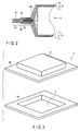
- FIG. 3 is a perspective view illustrating the case used in the battery of FIGS. 1A and 1B .
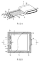
- FIG. 4 is a perspective view illustrating a state that the electrode group used in the battery of FIGS. 1A and 1B is partially exploded.
- the battery of FIGS. 1A and 1B is a nonaqueous electrolyte battery (for example, a lithium ion secondary battery).
- This nonaqueous electrolyte battery includes a case 1, an electrode group 2, a positive electrode lead 3, a negative electrode lead 4, and a nonaqueous electrolyte (not illustrated).
- the case 1 includes a first film comprising a first convex portion 5 overhanging outwardly in a rectangular shape and a second film comprising a second convex portion 6 overhanging outwardly in a rectangular shape.
- the first and second convex portions 5 and 6 of the first and second films are formed, for example, by performing deep drawing, for example, on a laminate film.
- a portion extending approximately horizontally around an opening end of the first convex portion 5 is an edge portion 5a
- a portion extending approximately horizontally around an opening end of the second convex portion 6 is an edge portion 6a. If the edge portion 5a of the first film and the edge portion 6a of the second film are bonded through heat sealing, a space enveloped by the first and second convex portions 5 and 6 is sealed. Therefore, the electrode group can be housed in this space. That is, a portion formed by the first and second convex portions 5 and 6 serves as a case portion.
- the laminate film may include a sealant layer 7, a resin layer 8 and a metal layer 9 interposed between the sealant layer 7 and the resin layer 8.
- the sealant layer forms an inner surface of the case 1, the edge portions 5a and 6a can be bonded through heat sealing.
- a material for the sealant layer 7 include a thermoplastic resin such as polypropylene (PP) or polyethylene (PE).
- the metal layer 9 include an aluminum foil and an aluminum alloy foil.
- the resin layer 8 is provided to insulate and protect the metal layer 9.
- a material for the resin layer 8 include polymers such as nylon or polyethylene terephthalate (PET).
- PET polyethylene terephthalate
- examples of the aluminum-containing laminate film may include a layered structure of nylon/aluminum/polyethylene and a layered structure of nylon/aluminum/polypropylene.
- a polyethylene terephthalate layer may be provided on an outer side of the nylon layer.
- the electrode group 2 is obtained by spirally winding the positive electrode 10, the negative electrode 11, and the separator 12 interposed therebetween in a flat shape.
- the positive electrode 10 includes, for example, a positive electrode current collector made of a metal foil in a strip shape, a positive electrode current collector tab 10a parallel to a long side of the positive electrode current collector, and a positive electrode active material layer 10b formed in the positive electrode current collector except for at least a part corresponding to the positive electrode current collector tab 10a.
- the negative electrode 11 includes a negative electrode current collector made of a metal foil in a strip shape, a negative electrode current collector tab 11a parallel to a long side of the negative electrode current collector, and a negative electrode active material layer 11b formed in the negative electrode current collector except for at least a part corresponding to the negative electrode current collector tab 11a.
- the positive electrode 10, the separator 12, and the negative electrode 11 are wound by deviating the positions of the positive electrode 10 and the negative electrode 11 such that the positive electrode current collector tab 10a projects from the separator 12 in a winding axis direction of the electrode group, and the negative electrode current collector tab 11a projects from the separator 12 in a direction opposite to the positive electrode current collector tab projecting direction.
- the positive electrode current collector tab 10a projects from one end face relative to the negative electrode 11 and the separator 12 while it is rolled in a spiral shape as illustrated in FIG. 4 .
- the negative electrode current collector tab 11a projects relative to the positive electrode 10 and the separator 12 while it is rolled in a spiral shape.
- a width in a direction perpendicular to the projecting direction of each of the positive and negative electrode current collector tabs 10a and 11a is equal to the width of the electrode group 2.
- the nonaqueous electrolytic solution (not illustrated) is impregnated into the electrode group 2.
- the positive electrode current collector tab 10a is spirally wound, and the end portion of the positive electrode current collector tab 10a overlap each other and are electrically connected to each other.
- the overlappingly connected end portion of the positive electrode current collector tab 10a is connected to an end portion of the positive electrode lead 3.
- the connecting portion is denoted by reference symbol "C”.
- the negative electrode current collector tab 11a is spirally wound, and the end portion of the negative electrode current collector tab 11a overlap each other and are electrically connected to each other.
- the overlappingly connected end portion of the negative electrode current collector tab 11a is connected to an end portion of the negative electrode lead 4.
- the connecting between the positive electrode current collector tab 10a and the positive electrode lead 3 and the connecting between the negative electrode current collector tab 11a and the negative electrode lead 4 are performed, for example, through ultrasonic welding, laser welding, resistance welding, and the like.
- the edge portion 5a of the first film of the case 1 is overlappingly bonded to the edge portion 6a of the second film so that electrode group 2 is housed in the case portion formed by the first and second convex portions 5 and 6.
- the positive electrode current collector tab 10a is arranged in one of four sides formed by overlappingly bonding the edge portions 5a and 6a of the first and second films, and the end portion of the positive electrode lead 3 extends outwardly through this one side.
- the negative electrode current collector tab 11a is arranged in the side opposite to this one side, and the end portion of the negative electrode lead 4 extends outwardly through this opposite side in a direction opposite to that of the positive electrode lead 3.
- thermoplastic insulation film 13 is arranged on a heat-sealed portion of each side of the positive electrode lead 3a, and the other strip-like thermoplastic insulation film 13 is arranged on a heat-sealed portion of each side of the negative electrode lead 4.
- the thermoplastic insulation film 13 may include, for example, a film containing polyolefins modified with acids.
- the edge portion 5a of the first film and the edge portion 6a of the second film are bonded through heat sealing. Heat sealing the edge portions 5a and 6a is performed while an internal space of the case is depressurized or vacuumized, after electrolytic solution injection.
- the heat-sealing width of the edge portion where the positive and negative electrode leads 3 and 4 are heat-sealed is equal to width Y.
- the heat-sealing width of other edge portions is equal to width X.
- the heat-sealed portion E1 in the edge portions 5a and 6a is hatched.
- the positive and negative electrode leads 3 and 4 are heat-sealed on inner surfaces of the edge portions 5a and 6a with a width Y by interposing the thermoplastic insulation film 13.
- a bonding portion 16 where the sealant layers 7 are bonded to each other through heat sealing is formed as illustrated in FIG. 2 .
- a portion located inwardly from the heat-sealed portion E1 of width Y is a non-heat-sealed portion E2 where heat sealing is not performed.
- the end portions of the positive electrode current collector tab 10a and the negative electrode current collector tab 11a are interposed between the edge portions 5a and 6a in the non-heat-sealed portion E2 while the end portions of the positive electrode current collector tab 10a and the negative electrode current collector tab 11a are fixed to the positive electrode lead 3 and the negative electrode lead 4, respectively.
- the end portions of the positive electrode current collector tab 10a and the negative electrode current collector tab 11a are directly nipped from the non-heat-sealed portion of the case 1, and the atmospheric pressure from the outside is applied to the case 1.
- the nonaqueous electrolyte battery when used as in-vehicle equipment or in a forklift, and strong vibration is applied to the battery, it is possible to suppress a deviation of the electrode position and avoid a crack or fracture in the positive electrode current collector tab 10a and the negative electrode current collector tab 11a. As a result, it is possible to suppress battery internal resistance increase due to vibration or impact applied to the battery.
- Materials of the positive and negative electrode current collectors and the positive and negative electrode current collector tabs are preferably selected depending on a type of the employed active material.
- a carbon-based material for example, aluminum or aluminum alloy is used in the positive electrode current collector and the positive electrode current collector tab, and a metal such as copper, nickel, or nickel-plated iron is used in the negative electrode current collector and the negative electrode current collector tab.
- examples of the materials for the negative electrode current collector and the negative electrode current collector tab may include a metal such as copper, nickel, nickel-plated iron, aluminum or aluminum alloy.
- the positive and negative electrode leads 3 and 4 are not particularly limited.
- the positive and negative electrode leads 3 and 4 are preferably made of the same material as those of the positive and negative electrode current collector tabs 10a and 11a.
- the lead is preferably made of aluminum or aluminum alloy.
- the lead is preferably made of copper and the like.
- the shape of the electrode group is not particularly limited thereto.
- an end portion of at least one of the positive electrode current collector tab and the negative electrode current collector tab is provided in a non-heat-sealed part of the edge portion of the case. Therefore, it is possible to suppress a deviation of the electrode when vibration or impact is applied to the battery and suppress a crack or fracture of the current collector tab. As a result, it is possible to suppress internal resistance increase when the battery is used while vibration or impact is applied to the battery.
- FIG. 5 is a plan view schematically illustrating the battery according to the second embodiment, in which a case is partially exploded.
- like reference numbers denote like elements as in FIGS. 1A to 4 , and description thereof will not be repeated.
- a nonaqueous electrolyte battery of FIG. 5 has the same structure as that of FIGS. 1A to 4 except for the first and second current collector tab connecting portions D.
- the first current collector tab connecting portion D is a portion where the positive electrode current collector tabs 10a are overlappingly connected to each other in a plurality of portions (for example, two portions) located on both sides of the connecting portion C for the positive electrode lead 3 of the positive electrode current collector tab 10a.
- the second current collector tab connecting portion D is a portion where the negative electrode current collector tabs 11a are connected to each other in a plurality of portions (for example, two portions) located on both sides of the connecting portion C for the negative electrode lead 4 of the negative electrode current collector tab 11a.
- the bonding between the current collector tabs is performed, for example, through ultrasonic welding, laser welding, resistance welding, and the like.
- the nonaqueous electrolyte battery of FIG. 5 has the connecting portion D where each of the positive and negative electrode current collector tabs 10a and 11a is overlappingly connected in addition to the connecting portion C where the positive and negative electrode leads 3 and 4 and the positive and negative electrode current collector tabs 10a and 11a are connected, it is possible to further increase an effect of suppressing a deviation of the electrode position when vibration or impact is applied to the nonaqueous electrolyte battery. As a result, it is possible to further suppress internal resistance increase due to vibration or impact applied to the battery.
- the positive and negative electrode current collector tabs 10a and 11a projecting in a spiral shape are compressed in a stacking direction (thickness direction) in the connecting portion D, it is possible to reduce a total thickness of the positive and negative electrode current collector tabs 10a and 11a. Therefore, it is possible to easily arrange the end portions of the positive and negative electrode current collector tabs 10a and 11a on the edge portion 5a of the case portion 5.
- the current collector tab where the first and second current collector tab connecting portions D are formed may be any one of the positive electrode and the negative electrode.
- the positive electrode current collector tab and the negative electrode current collector tab since at least one of the positive electrode current collector tab and the negative electrode current collector tab has a portion where the current collector tabs are connected to each other, it is possible to further suppress a deviation of the electrode when vibration or impact is applied to the battery. Therefore, it is possible to suppress internal resistance increase due to vibration or impact applied to the battery.
- the current collector tab projecting from an end portion of the electrode group in a spiral shape or a plurality of tabs projecting in the case of the stack type is/are fixed to the connecting portion in a stacking direction, it is possible to reduce a total thickness of overall layers of the current collector tab(s). Therefore, it is possible to easily arrange the end portion of the current collector tab in a non-heat-sealed part of the edge portion of the case.
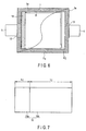
- FIG. 6 is a plan view schematically illustrating the battery according to the third embodiment, in which a case is partially exploded.
- a nonaqueous electrolyte battery of FIG. 6 has the same structure as that of FIGS. 1A to 5 except that an insulating member is employed.
- a first insulating member 14 having a strip shape is coated on an outer circumference of a positive electrode current collector tab 10a exposed from a separator and is interposed between an inner surface of the case and the positive electrode current collector tab 10a.
- a second insulating member 14 (not illustrated) having a strip shape is coated on an outer circumference of the negative electrode current collector tab 11a exposed from the separator and is interposed between the negative electrode current collector tab 11a and an inner surface of the case.
- an insulation tape such as a polypropylene tape or a polyethylene terephthalate [PET] tape
- PET polyethylene terephthalate
- the insulating member 14 may be arranged on the positive and negative electrode current collector tabs 10a and 11a without forming the first and second current collector tab connecting portions D.
- the current collector tab coated with the insulating member 14 may be any one of the positive electrode or the negative electrode.
- the insulating member is interposed between the end portion of at least one of the positive electrode current collector tab and the negative electrode current collector tab and the inner surface of the case, it is possible to prevent a possibility of a short-circuit between the positive and negative electrodes by interposing a metal layer even when a sealant layer on an inner surface of the case is melt or cracked, and the metal layer of the case is exposed.
- FIG. 7 is a plan view illustrating a positive electrode used in an electrode group of the battery according to the fourth embodiment
- FIG. 8 is a plan view illustrating a negative electrode used in the electrode group of the battery according to the fourth embodiment.
- FIG. 9 is a plan view schematically illustrating the battery according to the fourth embodiment, in which a case is partially exploded.
- FIG. 10 is an enlarged plan view illustrating a state before the electrode group of the battery of FIG. 9 is coated with an insulating member.
- like reference numbers denote like elements as in FIGS. 1A to 6 , and description thereof will not be repeated.
- the positive electrode 10 includes, for example, a positive electrode current collector made of a metal foil in a rectangular sheet shape, a positive electrode current collector tab 10a being one end portion parallel to a short side of the positive electrode current collector, and a positive electrode active material layer 10b formed on at least one surface of the positive electrode current collector except for at least a portion corresponding to the positive electrode current collector tab 10a.
- a positive electrode current collector made of a metal foil in a rectangular sheet shape
- a positive electrode current collector tab 10a being one end portion parallel to a short side of the positive electrode current collector
- a positive electrode active material layer 10b formed on at least one surface of the positive electrode current collector except for at least a portion corresponding to the positive electrode current collector tab 10a.
- the negative electrode 11 includes, for example, a negative electrode current collector made of a metal foil in a rectangular sheet shape, a negative electrode current collector tab 11a being one end portion parallel to the short side of the negative electrode current collector, and a negative electrode active material layer 11b formed on at least one surface of the negative electrode current collector except for at least a portion corresponding to the negative electrode current collector tab 11a.
- the stack type electrode group 2 is manufactured by alternately stacking the positive electrode 10, the negative electrode 11, and the separator 12 interposed therebetween. As illustrated in FIG. 1B , a plurality of positive electrode current collector tabs 10a project relative to the negative electrode 11 and the separator 12 from one of both end portions of the electrode group 2. Meanwhile, a plurality of negative electrode current collector tabs 11a project relative to the positive electrode 10 and the separator 12 from the other end portion in the opposite side.
- the positive electrode current collector tab 10a and the negative electrode current collector tab 11a are directly nipped into the case 1, and the first and second current collector tab connecting portions D are formed as described in the second embodiment.
- each of the positive electrode current collector tabs 10a the corner portions in both sides are C-chamfered to provide a trapezoidal shape as a whole.
- the corner portions in both sides are C-chamfered to provide a trapezoidal shape as a whole.
- the positive electrode current collector tab 10a and the negative electrode current collector tab 11a are coated with the insulating member 14 having a strip shape as illustrated in FIG. 9 , it is possible to easily cover the positive electrode current collector tab 10a and the negative electrode current collector tab 11a by the insulating member 14 without exposing the positive electrode current collector tab 10a and the negative electrode current collector tab 11a, because the widths in a direction perpendicular to the projecting direction of the positive electrode current collector tab 10a and the negative electrode current collector tab 11a are smaller than the width of the insulating member 14.
- the insulating member 14 may be arranged on the positive and negative electrode current collector tabs 10a and 11a without forming the first and second current collector tab connecting portions D.
- the current collector tab coated with the insulating member 14 may be any one of the positive and the negative electrodes.
- the current collector tab having the R-shaped or chamfered corner portion may be any one of the positive and the negative electrodes.
- the corner portion in the end portion of at least one of the positive electrode current collector tab and the negative electrode current collector tab is notched or chamfered. Therefore, it is possible to facilitate a work for covering the surface of the end portion with the insulating member.
- FIG. 11 is a plan view schematically illustrating the battery according to the fifth embodiment, in which the case is partially exploded.
- like reference numbers denote like elements as in FIGS. 1A to 10 , and description thereof will not be repeated.
- a nonaqueous electrolyte battery of FIG. 11 has the same structure as that of FIG. 9 except that a corner portion of a positive electrode is notched.
- Areas of positive and negative electrodes and a separator are not particularly limited. As illustrated in FIG. 11 , in a case where a relationship is established as below: ⁇ ⁇ ⁇ ⁇ ⁇ ⁇
- a relationship between the area of the positive electrode active material-containing layer and the area of the negative electrode active material-containing layer may be set as follows.
- the area of the negative electrode active material-containing layer is preferably set to be larger than the area of the positive electrode active material-containing layer.
- the area of the negative electrode active material-containing layer may be set to be smaller than the area of the positive electrode active material-containing layer.
- the area of the negative electrode active material-containing layer may be set to be larger than the area of the positive electrode active material-containing layer.
- the area of the active material-containing layer of the positive electrode is different from the area of the active material-containing layer of the negative electrode, and the corner portion of the active material-containing layer of the electrode having a smaller area is notched or chamfered. Therefore, when the electrode is deviated, or the corner portion of the electrode is deformed due to vibration or impact applied to the battery, it is possible to prevent the corner portion of the electrode from tearing the separator and prevent an internal short-circuit.
- the width of at least one of the positive electrode current collector tab and the negative electrode current collector tab is preferably set as follows.
- the width (L1 in FIGS. 4 and 7 ) of the positive electrode current collector tab 10 in the projecting direction is set to be greater than or equal to 4% and less than or equal to 28% of the width (L2 in FIGS. 4 and 7 ) of the positive electrode active material layer 10b parallel to the projecting direction. Since it is possible to increase a portion directly nipped from the case 1 by increasing the width of the positive electrode current collector tab 10a in the projecting direction, it is possible to further reduce internal resistance increase of the battery due to vibration or impact. From the viewpoint of internal resistance increase of the battery, it is advantageous to increase the width of the positive electrode current collector tab 10a in the projecting direction. However, if the width of the positive electrode current collector tab 10a is excessively large, the energy density by volume may be lowered.
- the width of the negative electrode current collector tab 11a in the projecting direction (L3 in FIGS. 4 and 8 ) is set to be greater than or equal to 3% and less than or equal to 20% of the width (L4 in FIGS. 4 and 8 ) of the negative electrode active material layer 11b parallel to the projecting direction. Since it is possible to increase a portion directly nipped from the case 1 by increasing the width of the negative electrode current collector tab 11a in the projecting direction, it is possible to reduce internal resistance increase of the battery due to vibration or impact. From the viewpoint of internal resistance increase of the battery, it is advantageous to increase the width of the negative electrode current collector tab 11a in the projecting direction. However, if the width of the negative electrode current collector tab 11a is excessively large, an energy density by volume may be lowered.
- the width of the positive electrode current collector tab 10a or the negative electrode current collector tab 11a in the projecting direction it is possible to further improve the effect of improving internal resistance change of the battery. Therefore, it is preferable to define the widths of the current collector tabs of both the positive and negative electrodes in the projecting direction.
- the positive electrode is manufactured, for example, by coating a slurry containing a positive electrode active material on a current collector made of an aluminum foil or an aluminum alloy foil.
- the positive electrode active material may include, but not particularly limited to, oxides, sulfides, polymers, and the like capable of absorbing or releasing lithium.
- the active material may include lithium manganese complex oxides, lithium nickel complex oxides, lithium cobalt complex oxides, lithium iron phosphates, and the like capable of obtaining a high positive electrode electric potential.
- the negative electrode is manufactured by coating a slurry containing a negative electrode active material on a current collector made of an aluminum foil or an aluminum alloy foil.
- the negative electrode active material may include, but not particularly limited to, metal oxides, metal sulfides, metal nitrides, alloys, and the like capable of absorbing or releasing lithium.
- the negative electrode active material is a substance having an electric potential for absorbing or releasing lithium ions of 0.4 V (vs Li/Li + ) or higher relative to the metal lithium electric potential. Since the negative electrode active material having such a lithium ion absorbing/releasing electric potential suppresses an alloy reaction between aluminum and lithium and an alloy reaction between aluminum alloy and lithium, aluminum or aluminum alloy can be used in the negative electrode current collector and elements relating to the negative electrode.
- such a negative electrode active material may include titanium oxides, lithium titanium oxides, tungsten oxides, amorphous tin oxides, tin silicon oxides, silicon oxides, and the like.
- the negative electrode active material includes lithium titanium complex oxides.
- the separator may be made of a microporous film, woven fabrics, non-woven fabrics, a stack of those materials or other materials, and the like. Materials of the separator may include polyethylene, polypropylene, ethylene-propylene copolymer, ethylene-butane copolymer, cellulose, and the like.
- a nonaqueous electrolytic solution prepared by dissolving electrolyte (for example, lithium salts) into a nonaqueous solvent
- the nonaqueous solvent may include, for example, ethylene carbonate (EC), propylene carbonate (PC), butylene carbonate (BC), dimethyl carbonate (DMC), diethyl carbonate (DEC), ethyl methyl carbonate (EMC), ⁇ -butyrolactone ( ⁇ -BL), sulfolane, acetonitrile, 1,2-dimethoxyethane, 1,3-dimethoxypropane, dimethyl ether, tetrahydrofuran (THF), 2-methyl tetrahydrofuran, and the like.
- EC ethylene carbonate
- PC propylene carbonate
- BC dimethyl carbonate
- DEC diethyl carbonate
- EMC ethyl methyl carbonate
- ⁇ -BL ⁇ -butyrolactone
- the aforementioned materials of the nonaqueous solvent may be used solely or as a combination of two or more materials described above.
- the electrolyte may include, for example, lithium salts such as lithium perchlorate (LiClO 4 ), lithium hexafluorophosphate (LiPF 6 ), lithium tetrafluoroborate (LiBF 4 ), lithium hexafluoroarsenate (LiAsF 6 ), and lithium trifluoromethanesulfonate (LiCF 3 SO 3 ).
- the aforementioned materials of the electrolyte may be used solely or as a combination of two or more materials described above.
- a dissolving amount of the electrolyte with respect to the nonaqueous solvent is preferably set to 0.2 to 3 mol/L.
- the embodiments is not limited thereto.
- the embodiments may be applicable to other types of batteries such as an alkaline battery.
- the number of electrode groups may be set to 1 or 2.
- the embodiments may be applicable to a battery pack comprising a single or a plurality of batteries according to the embodiment and a charge/discharge control circuit.
- a nonaqueous electrolyte battery having the structure illustrated in FIG. 1A was manufactured through the following method.
- a slurry was prepared by adding lithium cobalt oxides (LiCoO 2 ) powder as a positive electrode active material of 90 weight%, acetylene black of 3 weight%, graphite of 3 weight%, and polyvinylidene fluoride (PVdF) of 4 weight% to N-methyl pyrrolidone (NMP) and mixing them.
- This slurry was coated on both surfaces of a current collector made of aluminum with a thickness of 12 ⁇ m and was dried. Then, a press process was performed, so that a positive electrode 10 having a thickness of 58 ⁇ m was manufactured.
- a slurry was prepared by adding lithium titanium oxides (Li 4 Ti 5 O 12 ) powder as a negative electrode active material of 95 weight% having a spinel structure, acetylene black of 2.5 weight% as a conducting agent, polyvinylidene fluoride (PVdF) of 2.5 weight% to N-methyl pyrrolidone (NMP) solution and mixing them.
- This slurry was coated on both surfaces of a current collector made from an aluminum foil having a thickness of 12 ⁇ m and was dried. The, a press process was performed, so that a negative electrode 11 having a thickness of 44 ⁇ m was manufactured.
- the obtained positive electrode 10 was cut in a strip shape such that a portion of the current collector where an active material-containing layer is not formed is positioned in one long side. A portion of the current collector where the active material-containing layer is not formed serves as the current collector tab 10a.
- a width L1 of the positive electrode current collector tab 10a in a short-side direction (projecting direction) was set to 14 mm, and a width L2 of the positive electrode active material layer 10b parallel to the short-side direction was set to 88 mm. Width L1 of the positive electrode current collector tab 10a was 15.9% of width L2 of the positive electrode active material layer 10b.
- the negative electrode 11 was cut in a strip shape such that a portion of the current collector where the active material-containing layer is not formed is positioned in one long side. A portion of the current collector where the active material-containing layer is not formed serves as a current collector tab 11a.
- a width L3 of the negative electrode current collector tab 11a in a short-side direction was set to 10 mm, and a width L4 of the negative electrode active material layer 11b parallel to short-side direction was set to 92 mm. Width L3 of the negative electrode current collector tab 11a was 10.9% of width L4 of the negative electrode active material layer 11b.
- the positive electrode 10 and the negative electrode 11 were wound in a flat spiral shape by interposing the separator 12 made of a polyethylene porous film with a thickness of 20 ⁇ m therebetween.
- the positive electrode current collector tab 10a rolled in a spiral shape was made to project from one end face relative to the negative electrode 11 and the separator 12, and the negative electrode current collector tab 11a rolled in a spiral shape was made to project from the other end face relative to positive electrode 10 and the separator 12.
- the separator 12 was positioned in the outermost circumference of the electrode group 2. A portion of the positive electrode current collector tab 10a exposed from the separator 12 had a width of 8 mm, and a portion of the negative electrode current collector tab 11a exposed from the separator 12 had a width of 8 mm.
- an aluminum foil having a thickness of 0.2 mm, a width of 30 mm, and a length of 50 mm was prepared.
- a part of the aluminum foil was covered by a polypropylene film with an acid-modification (having a thickness of 0.1 mm, a width of 38 mm, and a length of 12 mm) as a thermoplastic insulation film.
- the positive electrode lead 3 and the negative electrode lead 4 were connected to the positive electrode current collector tab 10a and the negative electrode current collector tab 11a, respectively, through ultrasonic welding.
- Cup-molding was performed for the case made of a laminate film with a thickness of 0.11 mm using a press mold comprising a male mold having a size of 95 mm by 96 mm.
- the laminate film has a layered structure comprising nylon, aluminum and cast-polypropylene.
- the first and second films were obtained by cutting excessive margins such that an exterior size becomes 140 mm by 120 mm, a width of edge portions 5a and 6b in the positive electrode lead side becomes 21.5 mm, a width of the edge portions 5a and 6b in the negative electrode lead side becomes 19.5 mm, widths of other portions (without the lead) become 10 mm.
- the electrode group 2 After the electrode group 2 is housed in the first convex portion 5 of the first film of the case 1, the electrode group was enveloped with the first and second convex portions 5 and 6 by overlapping the edge portions 5a and 6a of the first and second films each other.
- the positive electrode current collector tab 10a was arranged in one of four sides formed by overlapping the edge portions 5a and 6a of the first and second films each other, and an end portion of the positive electrode lead 3 was made to extend outwardly through this one side.
- the negative electrode current collector tab 11a was arranged in the side opposite to this one side, and an end portion of the negative electrode lead 4 was made to extend outwardly through this opposite side. The extending direction of the negative electrode lead 4 was opposite to that of the positive electrode lead 3.
- a part of the positive electrode current collector tab 10a from the end face to 8.5 mm was arranged between the edge portions 5a of the first film and the edge portion 6a of the second film.
- a part of the negative electrode current collector tab 11a from the end face to 6.5 mm was arranged between the edge portion 5a of the first film and the edge portion 6a of the second film.
- the edge portions 5a and 6a in a pair of sides through which the positive and negative electrode leads 3 and 4 are extended and one of a pair of sides where the positive and negative electrode leads 3 and 4 do not extend were bonded through heat sealing under an atmospheric pressure.
- the nonaqueous electrolyte was injected into the case from a gap between the edge portions 5a and 6a in the remaining one side where heat sealing is not performed, so that the nonaqueous electrolytic solution was impregnated into the electrode group.
- edge portions 5a and 6a in the one side used to inject the electrolytic solution were bonded through heat sealing with a sealing width of 10 mm under a depressurized atmosphere of 11.3 kPa to seal the case, so that the lithium ion secondary battery having a structure of FIG. 1A was obtained.
- the positive and negative electrode leads 3 and 4 were connected to the electrode group 2 through ultrasonic welding. Then, in the positive electrode current collector tabs 10a in both sides of the connecting portion C for the positive electrode lead 3, the positive electrode current collector tabs 10a were connected to each other through ultrasonic welding, so that the first current collector tab connecting portion D was formed. Similarly, in the negative electrode current collector tabs 11a in both sides of the connecting portion C for the negative electrode lead 4, the negative electrode current collector tab 11a were connected through ultrasonic welding, so that the second current collector tab connecting portion D was formed. The connecting area was set to 12 mm by 2.4 mm.
- the lithium ion secondary battery of FIG. 5 was obtained except that the first and second current collector tab connecting portions D are provided.
- Example 1 Similar to Examples 1 and 2, the positive and negative electrode leads were connected, and the first and second current collector tab connecting portions D were formed for the coil type electrode group obtained as described in Example 1. Then, an insulation tape (having a width of 10 mm and a length of 98 mm) made of polypropylene was adhered onto the positive electrode current collector tab 10a and the negative electrode current collector tab 11a adjoining an inner surface of the case 1. Subsequently, similar to Example 1, a process of injecting a nonaqueous electrolytic solution and sealing was performed, so that a lithium ion secondary battery having the structure of FIG. 6 was obtained.
- an insulation tape having a width of 10 mm and a length of 98 mm
- a stack type electrode group was manufactured as follows by employing the positive electrode, the negative electrode, and the separator manufactured through the method of Example 1.
- the positive electrode 10 was cut into a size of 89 mm by 102 mm in a strip-like shape such that a part of the current collector (current collector tab 10a) where the active material-containing layer is not formed is positioned in one short side.
- a width L1 of the positive electrode current collector tab 10a in the short-side direction (projecting direction) was set to 14 mm, and a width L2 of the positive electrode active material layer 10b parallel to the short-side direction was set to 88 mm.
- Width L1 of the positive electrode current collector tab 10a was 15.9% of width L2 of the positive electrode active material layer 10b.
- the negative electrode 11 was cut into a size of 93 mm by 102 mm in a strip-like shape such that a part of the current collector (current collector tab 11a) where the active material-containing layer is not formed is positioned in one short side.
- a width L3 of the negative electrode current collector tab 11a in the short-side direction (projecting direction) was set to 10 mm
- a width L4 of the negative electrode active material layer 11b parallel to the short-side direction was set to 92 mm.
- Width L3 of the negative electrode current collector tab 11a was 10.9% of width L4 of the negative electrode active material layer 11b.
- the electrode group 2 was obtained by alternately stacking the positive electrode 10, the negative electrode 11, and the separator 12 interposed therebetween, projecting the positive electrode current collector tab 10a from one end face relative to the negative electrode 11 and the separator 12, and projecting the negative electrode current collector tab 11a from the other end face relative to the positive electrode 10 and the separator 12.
- the separator 12 was positioned in the outermost layer of the electrode group 2. A part of the positive electrode current collector tab 10a exposed from the separator had a width of 8 mm, and a part of the negative electrode current collector tab 11a exposed from the separator had a width of 8 mm.
- each corner portion of the positive electrode current collector tab 10a and the negative electrode current collector tab 11a was C-chamfered.
- a polypropylene insulation tape (having a width of 10 mm and a length of 98 mm) was adhered onto the positive electrode current collector tab 10a and the negative electrode current collector tab 11a adjoining an inner surface of the case 1.
- a process of injecting the nonaqueous electrolytic solution and sealing was performed, so that a lithium ion secondary battery having the structure of FIG. 9 was obtained.
- the corner portion 15 of the active material-containing layer 10a of the positive electrode 10 having an area smaller than that of the negative electrode 11 was chamfered, so that a lithium ion secondary battery having the structure of FIG. 11 was obtained.
- a lithium ion secondary battery having the structure of FIG. 12 was manufactured through the following method.
- stamping was performed for the positive and negative electrode current collector tabs 10a and 11a of the positive and negative electrodes 10 and 11 manufactured in Example 4 while only the connecting portions for the positive and negative electrode leads remain.
- the electrode group 2 was obtained by alternately stacking the positive electrode 10, the negative electrode 11, and the separator 12 interposed therebetween, projecting the positive electrode current collector tab 10a from one end face relative to the negative electrode 11 and the separator 12, and projecting the negative electrode current collector tab 11a from the other end face relative to the positive electrode 10 and the separator 12.
- a portion of the positive electrode current collector tab 10a exposed from the separator had a width of 8 mm
- a portion of the negative electrode current collector tab 11a exposed from the separator had a width of 8 mm.
- the positive and negative electrode leads 3 and 4 similar to those of Example 1 were connected to the positive and negative electrode current collector tabs 10a and 11a through ultrasonic welding.
- the connecting portions were denoted by reference symbol "C".
- cup-molding was performed using a press mold having a male mold having a size of 95 mm by 96 mm.
- the connecting portion C for the positive and negative electrode leads 3 and 4 out of the positive and negative electrode current collector tabs 10a and 11a was interposed between the edge portions 5a and 6a of the case 1, but other portions were positioned and housed in the case portion of the case 1.
- edge portions 5a and 6a in a pair of sides where the positive and negative electrode leads 3 and 4 are extended and one of a pair of sides where the positive and negative electrode leads 3 and 4 do not extend were connected through heat sealing under an atmospheric pressure.
- the nonaqueous electrolytic solution was injected into the case from a gap between the edge portions 5a and 6a in the remaining one side where heat sealing is not performed, so that the nonaqueous electrolytic solution was impregnated into the electrode group.
- connecting portions between the positive and negative electrode current collector tabs 10a and 11a and the positive and negative electrode leads 3 and 4 are interposed between the edge portions 5a and 6a of the case 1, and other remaining portions of the electrode group 2 are housed in the case portion 5.
- a vibration durability test was performed by repeatedly applying vibration at an acceleration of 12 G along each of the X-, Y-, and Z-axis directions for 3 hours.
- a battery internal resistance at a frequency of 1 kHz was measured before and after the test.
- Table 1 shows the highest internal resistances of the lithium ion secondary batteries after the test performed for each of the batteries obtained in Examples 1 to 5 and Comparative Example.
- the battery having the highest internal resistance after the test was disassembled, and it was observed whether or not there is a crack or fracture in the positive and negative electrode current collector tabs. The result thereof is also provided in Table 1.
- the width of the end portion in a direction perpendicular to the projecting direction of the positive and negative electrode current collector tabs is larger than the width of the positive and negative electrode leads, the positive and negative electrode current collector tabs in portions other than the connecting portions of the positive and negative electrode leads are directly interposed between the films of the case through sealing under a depressurized or vacuumized condition, and an atmospheric pressure is applied from the outside of the case, so that a movement of the electrode group inside the case portion of the case is suppressed, and a stress applied to the connecting portion between the current collector tabs and the leads is alleviated.
- At least one end portion of the positive and negative electrode current collector tabs is interposed between the edge portions of the case where heat sealing is not performed. Therefore, it is possible to suppress a crack or fracture in the current collector tab when vibration or impact is applied to the battery and suppress internal resistance increase of the battery.
Landscapes
- Chemical & Material Sciences (AREA)
- Chemical Kinetics & Catalysis (AREA)
- Electrochemistry (AREA)
- General Chemical & Material Sciences (AREA)
- Engineering & Computer Science (AREA)
- Inorganic Chemistry (AREA)
- Manufacturing & Machinery (AREA)
- Materials Engineering (AREA)
- Secondary Cells (AREA)
- Connection Of Batteries Or Terminals (AREA)
- Sealing Battery Cases Or Jackets (AREA)
Description
- Embodiments described herein relate to generally to a battery.
- In recent years, a lithium ion battery has been widely developed as a power supply of an electric vehicle, an electric motorcycle, a forklift, an automatic guided vehicle, an uninterrupted power supply (UPS) unit, a power storage facility, an emergency electric power supply unit, and the like. In response to such a trend, it is desirable to develop a lithium ion battery having a large scale, a large capacity, a high output power, and a low resistance. Meanwhile, in order to guarantee a cycle life over 10 years, for example, it is desirable to provide a structure sufficiently endurable to vibration or impact even in a large scale. As a casing of the battery, typically, a metal can or a casing made of an aluminum-containing laminate film may be employed. The laminate film casing is applied to a large-scaled battery or a thin battery because it guarantees freedom in shaping and does not necessitate an expensive mold unlike a metal can.
- The lithium ion battery comprising the laminate film casing has also been developed as a power supply for use in the fields described above. However, the lithium ion battery comprising the laminate film casing is susceptible to vibration or impact because it does not have sufficient rigidity compared to the metal can.
-
EP 2 006 935 A1 -
EP 1 202 371 A1EP 1 826 843 A1 are further prior art.EP 1 826 843 A1claim 1. - The invention is defined by
claim 1. -
-
FIG. 1A is a plan view schematically illustrating a battery according to a first embodiment; -
FIG. 1B is a cross-sectional view obtained by cutting the battery ofFIG. 1A along a line A-A; -
FIG. 2 is an enlarged cross-sectional view schematically illustrating main parts of the battery ofFIG. 1B ; -
FIG. 3 is a perspective view illustrating a case used in the battery ofFIGS. 1A and 1B ; -
FIG. 4 is a perspective view illustrating an electrode group partially exploded and used in the battery ofFIGS. 1A and 1B ; -
FIG. 5 is a plan view schematically illustrating a battery according to a second embodiment; -
FIG. 6 is a plan view schematically illustrating a battery according to a third embodiment; -
FIG. 7 is a plan view illustrating a positive electrode used in the battery according to a fourth embodiment; -
FIG. 8 is a plan view illustrating a negative electrode used in the battery according to the fourth embodiment; -
FIG. 9 is a plan view schematically illustrating the battery according to the fourth embodiment; -
FIG. 10 is an enlarged plan view illustrating the electrode group of the battery ofFIG. 9 before an insulating member is coated; -
FIG. 11 is a plan view schematically illustrating a battery according to a fifth embodiment; -
FIG. 12A is a plan view schematically illustrating a battery according to Comparative Example; and -
FIG. 12B is a cross-sectional view obtained by cutting the battery ofFIG. 12A along a line B-B. - According to an embodiment, there is provided a battery including an electrode group, a case, a positive electrode lead, and a negative electrode lead. The electrode group includes a positive electrode including an active material-containing layer, a negative electrode including an active material-containing layer, a separator interposed between the positive and negative electrodes, at least one positive electrode current collector tab projecting from one end portion of the electrode group, and at least one negative electrode current collector tab projecting from the other end portion of the electrode group. The case includes a case portion configured to house the electrode group and an edge portion which includes a heat sealed part configured to seal the case portion and a non-sealed part. A positive electrode lead is electrically connected to the at least one positive electrode current collector tab, and an end portion thereof extends outwardly through the edge portion of the case. A negative electrode lead is electrically connected to the at least one negative electrode current collector tab, and an end portion thereof extends outwardly through the edge portion of the case. The electrode group is housed in the case portion while an end portion of at least one of the at least one positive electrode current collector tab and the at least one negative electrode current collector tab is provided in the non-heat-sealed part.
- Hereinafter, embodiments will be described with reference to the accompanying drawings.
- According to a first embodiment, a battery includes an electrode group, a case, a positive electrode lead, and a negative electrode lead.
- The battery according to the first embodiment will be described with reference to
FIGS. 1A to 4 .FIG. 1A is a plan view schematically illustrating the battery according to the first embodiment, in which the case is partially exploded.FIG. 1B is a cross-sectional view obtained by cutting the battery ofFIG. 1A along a line A-A.FIG. 2 is an enlarged cross-sectional view schematically illustrating main parts of the battery ofFIG. 1B .FIG. 3 is a perspective view illustrating the case used in the battery ofFIGS. 1A and 1B .FIG. 4 is a perspective view illustrating a state that the electrode group used in the battery ofFIGS. 1A and 1B is partially exploded. - The battery of
FIGS. 1A and 1B is a nonaqueous electrolyte battery (for example, a lithium ion secondary battery). This nonaqueous electrolyte battery includes acase 1, anelectrode group 2, a positive electrode lead 3, anegative electrode lead 4, and a nonaqueous electrolyte (not illustrated). As illustrated inFIG. 3 , thecase 1 includes a first film comprising afirst convex portion 5 overhanging outwardly in a rectangular shape and a second film comprising asecond convex portion 6 overhanging outwardly in a rectangular shape. The first and secondconvex portions convex portion 5 is anedge portion 5a, and a portion extending approximately horizontally around an opening end of the secondconvex portion 6 is anedge portion 6a. If theedge portion 5a of the first film and theedge portion 6a of the second film are bonded through heat sealing, a space enveloped by the first and secondconvex portions convex portions FIG. 2 , for example, the laminate film may include a sealant layer 7, aresin layer 8 and a metal layer 9 interposed between the sealant layer 7 and theresin layer 8. Since the sealant layer forms an inner surface of thecase 1, theedge portions resin layer 8 is provided to insulate and protect the metal layer 9. Examples of a material for theresin layer 8 include polymers such as nylon or polyethylene terephthalate (PET). For example, examples of the aluminum-containing laminate film may include a layered structure of nylon/aluminum/polyethylene and a layered structure of nylon/aluminum/polypropylene. A polyethylene terephthalate layer may be provided on an outer side of the nylon layer. - As illustrated in
FIG. 4 , theelectrode group 2 is obtained by spirally winding thepositive electrode 10, thenegative electrode 11, and theseparator 12 interposed therebetween in a flat shape. Thepositive electrode 10 includes, for example, a positive electrode current collector made of a metal foil in a strip shape, a positive electrodecurrent collector tab 10a parallel to a long side of the positive electrode current collector, and a positive electrodeactive material layer 10b formed in the positive electrode current collector except for at least a part corresponding to the positive electrodecurrent collector tab 10a. Meanwhile, thenegative electrode 11 includes a negative electrode current collector made of a metal foil in a strip shape, a negative electrodecurrent collector tab 11a parallel to a long side of the negative electrode current collector, and a negative electrodeactive material layer 11b formed in the negative electrode current collector except for at least a part corresponding to the negative electrodecurrent collector tab 11a. - The
positive electrode 10, theseparator 12, and thenegative electrode 11 are wound by deviating the positions of thepositive electrode 10 and thenegative electrode 11 such that the positive electrodecurrent collector tab 10a projects from theseparator 12 in a winding axis direction of the electrode group, and the negative electrodecurrent collector tab 11a projects from theseparator 12 in a direction opposite to the positive electrode current collector tab projecting direction. Through such winding, in theelectrode group 2, the positive electrodecurrent collector tab 10a projects from one end face relative to thenegative electrode 11 and theseparator 12 while it is rolled in a spiral shape as illustrated inFIG. 4 . Meanwhile, from the other end face, the negative electrodecurrent collector tab 11a projects relative to thepositive electrode 10 and theseparator 12 while it is rolled in a spiral shape. A width in a direction perpendicular to the projecting direction of each of the positive and negative electrodecurrent collector tabs electrode group 2. The nonaqueous electrolytic solution (not illustrated) is impregnated into theelectrode group 2. - The positive electrode
current collector tab 10a is spirally wound, and the end portion of the positive electrodecurrent collector tab 10a overlap each other and are electrically connected to each other. The overlappingly connected end portion of the positive electrodecurrent collector tab 10a is connected to an end portion of the positive electrode lead 3. InFIG. 1A , the connecting portion is denoted by reference symbol "C". In addition, the negative electrodecurrent collector tab 11a is spirally wound, and the end portion of the negative electrodecurrent collector tab 11a overlap each other and are electrically connected to each other. The overlappingly connected end portion of the negative electrodecurrent collector tab 11a is connected to an end portion of thenegative electrode lead 4. The connecting between the positive electrodecurrent collector tab 10a and the positive electrode lead 3 and the connecting between the negative electrodecurrent collector tab 11a and thenegative electrode lead 4 are performed, for example, through ultrasonic welding, laser welding, resistance welding, and the like. - As illustrated in
FIG. 1A , theedge portion 5a of the first film of thecase 1 is overlappingly bonded to theedge portion 6a of the second film so thatelectrode group 2 is housed in the case portion formed by the first and secondconvex portions current collector tab 10a is arranged in one of four sides formed by overlappingly bonding theedge portions current collector tab 11a is arranged in the side opposite to this one side, and the end portion of thenegative electrode lead 4 extends outwardly through this opposite side in a direction opposite to that of the positive electrode lead 3. Each of the positive and negative electrodecurrent collector tabs edge portion 5a of the first film and theedge portion 6a of the second film. As illustrated inFIG. 1A , one strip-likethermoplastic insulation film 13 is arranged on a heat-sealed portion of each side of the positive electrode lead 3a, and the other strip-likethermoplastic insulation film 13 is arranged on a heat-sealed portion of each side of thenegative electrode lead 4. Thethermoplastic insulation film 13 may include, for example, a film containing polyolefins modified with acids. - The
edge portion 5a of the first film and theedge portion 6a of the second film are bonded through heat sealing. Heat sealing theedge portions FIG. 1A , the heat-sealed portion E1 in theedge portions edge portions thermoplastic insulation film 13. In the heat-sealed portion E1 indicated by width Y, abonding portion 16 where the sealant layers 7 are bonded to each other through heat sealing is formed as illustrated inFIG. 2 . In the edge portion where the positive and negative electrode leads 3 and 4 are heat-sealed, a portion located inwardly from the heat-sealed portion E1 of width Y is a non-heat-sealed portion E2 where heat sealing is not performed. The end portions of the positive electrodecurrent collector tab 10a and the negative electrodecurrent collector tab 11a are interposed between theedge portions current collector tab 10a and the negative electrodecurrent collector tab 11a are fixed to the positive electrode lead 3 and thenegative electrode lead 4, respectively. As a result, the end portions of the positive electrodecurrent collector tab 10a and the negative electrodecurrent collector tab 11a are directly nipped from the non-heat-sealed portion of thecase 1, and the atmospheric pressure from the outside is applied to thecase 1. For this reason, when the nonaqueous electrolyte battery is used as in-vehicle equipment or in a forklift, and strong vibration is applied to the battery, it is possible to suppress a deviation of the electrode position and avoid a crack or fracture in the positive electrodecurrent collector tab 10a and the negative electrodecurrent collector tab 11a. As a result, it is possible to suppress battery internal resistance increase due to vibration or impact applied to the battery. - Materials of the positive and negative electrode current collectors and the positive and negative electrode current collector tabs are preferably selected depending on a type of the employed active material. In a case where a carbon-based material is used in the negative electrode active material, for example, aluminum or aluminum alloy is used in the positive electrode current collector and the positive electrode current collector tab, and a metal such as copper, nickel, or nickel-plated iron is used in the negative electrode current collector and the negative electrode current collector tab. In addition, in a case where lithium titanate is used in the negative electrode active material, examples of the materials for the negative electrode current collector and the negative electrode current collector tab may include a metal such as copper, nickel, nickel-plated iron, aluminum or aluminum alloy.
- Materials of the positive and negative electrode leads 3 and 4 are not particularly limited. The positive and negative electrode leads 3 and 4 are preferably made of the same material as those of the positive and negative electrode
current collector tabs - Although description has been exemplarily made for a coil type electrode group in
FIGS. 1A and 1B , the shape of the electrode group is not particularly limited thereto. According to the first embodiment, an end portion of at least one of the positive electrode current collector tab and the negative electrode current collector tab is provided in a non-heat-sealed part of the edge portion of the case. Therefore, it is possible to suppress a deviation of the electrode when vibration or impact is applied to the battery and suppress a crack or fracture of the current collector tab. As a result, it is possible to suppress internal resistance increase when the battery is used while vibration or impact is applied to the battery. - A battery according to a second embodiment will be described with reference to
FIG. 5. FIG. 5 is a plan view schematically illustrating the battery according to the second embodiment, in which a case is partially exploded. InFIG. 5 , like reference numbers denote like elements as inFIGS. 1A to 4 , and description thereof will not be repeated. A nonaqueous electrolyte battery ofFIG. 5 has the same structure as that ofFIGS. 1A to 4 except for the first and second current collector tab connecting portions D. The first current collector tab connecting portion D is a portion where the positive electrodecurrent collector tabs 10a are overlappingly connected to each other in a plurality of portions (for example, two portions) located on both sides of the connecting portion C for the positive electrode lead 3 of the positive electrodecurrent collector tab 10a. Meanwhile, the second current collector tab connecting portion D is a portion where the negative electrodecurrent collector tabs 11a are connected to each other in a plurality of portions (for example, two portions) located on both sides of the connecting portion C for thenegative electrode lead 4 of the negative electrodecurrent collector tab 11a. The bonding between the current collector tabs is performed, for example, through ultrasonic welding, laser welding, resistance welding, and the like. - Since the nonaqueous electrolyte battery of
FIG. 5 has the connecting portion D where each of the positive and negative electrodecurrent collector tabs current collector tabs current collector tabs current collector tabs current collector tabs edge portion 5a of thecase portion 5. - In addition, according to the second embodiment, the current collector tab where the first and second current collector tab connecting portions D are formed may be any one of the positive electrode and the negative electrode.
- According to the second embodiment, since at least one of the positive electrode current collector tab and the negative electrode current collector tab has a portion where the current collector tabs are connected to each other, it is possible to further suppress a deviation of the electrode when vibration or impact is applied to the battery. Therefore, it is possible to suppress internal resistance increase due to vibration or impact applied to the battery. In addition, since the current collector tab projecting from an end portion of the electrode group in a spiral shape or a plurality of tabs projecting in the case of the stack type is/are fixed to the connecting portion in a stacking direction, it is possible to reduce a total thickness of overall layers of the current collector tab(s). Therefore, it is possible to easily arrange the end portion of the current collector tab in a non-heat-sealed part of the edge portion of the case.
- A battery according to a third embodiment will be described with reference to
FIG. 6. FIG. 6 is a plan view schematically illustrating the battery according to the third embodiment, in which a case is partially exploded. A nonaqueous electrolyte battery ofFIG. 6 has the same structure as that ofFIGS. 1A to 5 except that an insulating member is employed. - A first insulating
member 14 having a strip shape is coated on an outer circumference of a positive electrodecurrent collector tab 10a exposed from a separator and is interposed between an inner surface of the case and the positive electrodecurrent collector tab 10a. In addition, a second insulating member 14 (not illustrated) having a strip shape is coated on an outer circumference of the negative electrodecurrent collector tab 11a exposed from the separator and is interposed between the negative electrodecurrent collector tab 11a and an inner surface of the case. For example, an insulation tape (such as a polypropylene tape or a polyethylene terephthalate [PET] tape) may be used as the insulatingmember 14. - In this manner, if a portion of the positive electrode
current collector tab 10a and the negative electrodecurrent collector tab 11a exposed from the separator is covered by the insulating member, it is possible to prevent the positive electrode and the negative electrode from making contact with the metal layer 9 and avoid a possibility of an internal short-circuit even when a sealant layer 7 of a laminate film of the case is melt or cracked, and a metal layer 9 of the laminate film is exposed. - As illustrated in
FIG. 6 , in a case where aseparator 12 is positioned in the outermost layer of theelectrode group 2, it is possible to further improve an effect of preventing an internal short-circuit and facilitate a work for housing theelectrode group 2 in thecase 1 by coating a range from an end portion of theseparator 12 to an end portion of the positive electrodecurrent collector tab 10a, a range from an end portion of theseparator 12 to an end portion of the negative electrodecurrent collector tab 11a, or both the ranges with the insulatingmember 14. - According to the third embodiment, the insulating
member 14 may be arranged on the positive and negative electrodecurrent collector tabs member 14 may be any one of the positive electrode or the negative electrode. - According to the third embodiment, since the insulating member is interposed between the end portion of at least one of the positive electrode current collector tab and the negative electrode current collector tab and the inner surface of the case, it is possible to prevent a possibility of a short-circuit between the positive and negative electrodes by interposing a metal layer even when a sealant layer on an inner surface of the case is melt or cracked, and the metal layer of the case is exposed. Fourth Embodiment not falling under the present invention
- A battery according to a fourth embodiment will be described with reference to
FIGS. 7 to 10 .FIG. 7 is a plan view illustrating a positive electrode used in an electrode group of the battery according to the fourth embodiment, andFIG. 8 is a plan view illustrating a negative electrode used in the electrode group of the battery according to the fourth embodiment.FIG. 9 is a plan view schematically illustrating the battery according to the fourth embodiment, in which a case is partially exploded.FIG. 10 is an enlarged plan view illustrating a state before the electrode group of the battery ofFIG. 9 is coated with an insulating member. InFIGS. 7 to 10 , like reference numbers denote like elements as inFIGS. 1A to 6 , and description thereof will not be repeated. A nonaqueous electrolyte battery ofFIG. 9 has the same structure as that ofFIG. 6 except that a stack type electrode group is employed. The stack type electrode group is manufactured using apositive electrode 10 ofFIG. 7 and anegative electrode 11 ofFIG. 8 . As illustrated inFIG. 7 , thepositive electrode 10 includes, for example, a positive electrode current collector made of a metal foil in a rectangular sheet shape, a positive electrodecurrent collector tab 10a being one end portion parallel to a short side of the positive electrode current collector, and a positive electrodeactive material layer 10b formed on at least one surface of the positive electrode current collector except for at least a portion corresponding to the positive electrodecurrent collector tab 10a. Similarly, as illustrated inFIG. 8 , thenegative electrode 11 includes, for example, a negative electrode current collector made of a metal foil in a rectangular sheet shape, a negative electrodecurrent collector tab 11a being one end portion parallel to the short side of the negative electrode current collector, and a negative electrodeactive material layer 11b formed on at least one surface of the negative electrode current collector except for at least a portion corresponding to the negative electrodecurrent collector tab 11a. - The stack
type electrode group 2 is manufactured by alternately stacking thepositive electrode 10, thenegative electrode 11, and theseparator 12 interposed therebetween. As illustrated inFIG. 1B , a plurality of positive electrodecurrent collector tabs 10a project relative to thenegative electrode 11 and theseparator 12 from one of both end portions of theelectrode group 2. Meanwhile, a plurality of negative electrodecurrent collector tabs 11a project relative to thepositive electrode 10 and theseparator 12 from the other end portion in the opposite side. - As described in the first embodiment, the positive electrode
current collector tab 10a and the negative electrodecurrent collector tab 11a are directly nipped into thecase 1, and the first and second current collector tab connecting portions D are formed as described in the second embodiment. - As illustrated in
FIG. 10 , in each of the positive electrodecurrent collector tabs 10a, the corner portions in both sides are C-chamfered to provide a trapezoidal shape as a whole. Similarly, in each of the negative electrodecurrent collector tabs 11a, the corner portions in both sides are C-chamfered to provide a trapezoidal shape as a whole. - If the positive electrode
current collector tab 10a and the negative electrodecurrent collector tab 11a are coated with the insulatingmember 14 having a strip shape as illustrated inFIG. 9 , it is possible to easily cover the positive electrodecurrent collector tab 10a and the negative electrodecurrent collector tab 11a by the insulatingmember 14 without exposing the positive electrodecurrent collector tab 10a and the negative electrodecurrent collector tab 11a, because the widths in a direction perpendicular to the projecting direction of the positive electrodecurrent collector tab 10a and the negative electrodecurrent collector tab 11a are smaller than the width of the insulatingmember 14. - According to the fourth embodiment, the insulating
member 14 may be arranged on the positive and negative electrodecurrent collector tabs member 14 may be any one of the positive and the negative electrodes. Furthermore, the current collector tab having the R-shaped or chamfered corner portion may be any one of the positive and the negative electrodes. - According to the fourth embodiment, the corner portion in the end portion of at least one of the positive electrode current collector tab and the negative electrode current collector tab is notched or chamfered. Therefore, it is possible to facilitate a work for covering the surface of the end portion with the insulating member.
- A battery according to a fifth embodiment will be described with reference to
FIG. 11. FIG. 11 is a plan view schematically illustrating the battery according to the fifth embodiment, in which the case is partially exploded. InFIG. 11 , like reference numbers denote like elements as inFIGS. 1A to 10 , and description thereof will not be repeated. A nonaqueous electrolyte battery ofFIG. 11 has the same structure as that ofFIG. 9 except that a corner portion of a positive electrode is notched. - Areas of positive and negative electrodes and a separator are not particularly limited. As illustrated in
FIG. 11 , in a case where a relationship is established as below:
- wherein α is an area of active material-containing
layer 10b ofpositive electrode 10, β is an area of active material-containinglayer 11b ofnegative electrode 11, and γ is an area ofseparator 12, - a pair of
corner portions 15 of the active material-containinglayer 10b of thepositive electrode 10 having the smallest area are preferably R-shaped or chamfered. As a result, when the electrode is deviated, or thecorner portion 15 of thepositive electrode 10 is deformed due to vibration or impact applied to the battery, it is possible to prevent an internal short-circuit by preventing thecorner portion 15 of thepositive electrode 10 from tearing theseparator 12. - A relationship between the area of the positive electrode active material-containing layer and the area of the negative electrode active material-containing layer may be set as follows. For example, in a case where a carbon-based material is used in the negative electrode active material, the area of the negative electrode active material-containing layer is preferably set to be larger than the area of the positive electrode active material-containing layer. In addition, in a case where lithium titanate is used in the negative electrode active material, the area of the negative electrode active material-containing layer may be set to be smaller than the area of the positive electrode active material-containing layer. Alternatively, the area of the negative electrode active material-containing layer may be set to be larger than the area of the positive electrode active material-containing layer.
- According to the fifth embodiment, the area of the active material-containing layer of the positive electrode is different from the area of the active material-containing layer of the negative electrode, and the corner portion of the active material-containing layer of the electrode having a smaller area is notched or chamfered. Therefore, when the electrode is deviated, or the corner portion of the electrode is deformed due to vibration or impact applied to the battery, it is possible to prevent the corner portion of the electrode from tearing the separator and prevent an internal short-circuit.
- In the first to fifth embodiments, the width of at least one of the positive electrode current collector tab and the negative electrode current collector tab is preferably set as follows.
- The width (L1 in
FIGS. 4 and7 ) of the positive electrodecurrent collector tab 10 in the projecting direction is set to be greater than or equal to 4% and less than or equal to 28% of the width (L2 inFIGS. 4 and7 ) of the positive electrodeactive material layer 10b parallel to the projecting direction. Since it is possible to increase a portion directly nipped from thecase 1 by increasing the width of the positive electrodecurrent collector tab 10a in the projecting direction, it is possible to further reduce internal resistance increase of the battery due to vibration or impact. From the viewpoint of internal resistance increase of the battery, it is advantageous to increase the width of the positive electrodecurrent collector tab 10a in the projecting direction. However, if the width of the positive electrodecurrent collector tab 10a is excessively large, the energy density by volume may be lowered. - Similarly, the width of the negative electrode
current collector tab 11a in the projecting direction (L3 inFIGS. 4 and8 ) is set to be greater than or equal to 3% and less than or equal to 20% of the width (L4 inFIGS. 4 and8 ) of the negative electrodeactive material layer 11b parallel to the projecting direction. Since it is possible to increase a portion directly nipped from thecase 1 by increasing the width of the negative electrodecurrent collector tab 11a in the projecting direction, it is possible to reduce internal resistance increase of the battery due to vibration or impact. From the viewpoint of internal resistance increase of the battery, it is advantageous to increase the width of the negative electrodecurrent collector tab 11a in the projecting direction. However, if the width of the negative electrodecurrent collector tab 11a is excessively large, an energy density by volume may be lowered. - By defining the width of the positive electrode
current collector tab 10a or the negative electrodecurrent collector tab 11a in the projecting direction, it is possible to further improve the effect of improving internal resistance change of the battery. Therefore, it is preferable to define the widths of the current collector tabs of both the positive and negative electrodes in the projecting direction. - Hereinafter, the positive electrode, the negative electrode, the separator, and the electrolytic solution applicable to the first to fifth embodiments will be described.
- The positive electrode is manufactured, for example, by coating a slurry containing a positive electrode active material on a current collector made of an aluminum foil or an aluminum alloy foil. The positive electrode active material may include, but not particularly limited to, oxides, sulfides, polymers, and the like capable of absorbing or releasing lithium. Preferably, the active material may include lithium manganese complex oxides, lithium nickel complex oxides, lithium cobalt complex oxides, lithium iron phosphates, and the like capable of obtaining a high positive electrode electric potential. Similarly, the negative electrode is manufactured by coating a slurry containing a negative electrode active material on a current collector made of an aluminum foil or an aluminum alloy foil. The negative electrode active material may include, but not particularly limited to, metal oxides, metal sulfides, metal nitrides, alloys, and the like capable of absorbing or releasing lithium. Preferably, the negative electrode active material is a substance having an electric potential for absorbing or releasing lithium ions of 0.4 V (vs Li/Li+) or higher relative to the metal lithium electric potential. Since the negative electrode active material having such a lithium ion absorbing/releasing electric potential suppresses an alloy reaction between aluminum and lithium and an alloy reaction between aluminum alloy and lithium, aluminum or aluminum alloy can be used in the negative electrode current collector and elements relating to the negative electrode. For example, such a negative electrode active material may include titanium oxides, lithium titanium oxides, tungsten oxides, amorphous tin oxides, tin silicon oxides, silicon oxides, and the like. Preferably, the negative electrode active material includes lithium titanium complex oxides. The separator may be made of a microporous film, woven fabrics, non-woven fabrics, a stack of those materials or other materials, and the like. Materials of the separator may include polyethylene, polypropylene, ethylene-propylene copolymer, ethylene-butane copolymer, cellulose, and the like.
- As the electrolytic solution, a nonaqueous electrolytic solution prepared by dissolving electrolyte (for example, lithium salts) into a nonaqueous solvent is used. The nonaqueous solvent may include, for example, ethylene carbonate (EC), propylene carbonate (PC), butylene carbonate (BC), dimethyl carbonate (DMC), diethyl carbonate (DEC), ethyl methyl carbonate (EMC), γ-butyrolactone (γ-BL), sulfolane, acetonitrile, 1,2-dimethoxyethane, 1,3-dimethoxypropane, dimethyl ether, tetrahydrofuran (THF), 2-methyl tetrahydrofuran, and the like. The aforementioned materials of the nonaqueous solvent may be used solely or as a combination of two or more materials described above. The electrolyte may include, for example, lithium salts such as lithium perchlorate (LiClO4), lithium hexafluorophosphate (LiPF6), lithium tetrafluoroborate (LiBF4), lithium hexafluoroarsenate (LiAsF6), and lithium trifluoromethanesulfonate (LiCF3SO3). The aforementioned materials of the electrolyte may be used solely or as a combination of two or more materials described above. A dissolving amount of the electrolyte with respect to the nonaqueous solvent is preferably set to 0.2 to 3 mol/L.
- Although the nonaqueous electrolyte battery is employed in the embodiments, the embodiments is not limited thereto. The embodiments may be applicable to other types of batteries such as an alkaline battery. The number of electrode groups may be set to 1 or 2. In addition, the embodiments may be applicable to a battery pack comprising a single or a plurality of batteries according to the embodiment and a charge/discharge control circuit.
- Hereinafter, examples will be described.
- A nonaqueous electrolyte battery having the structure illustrated in
FIG. 1A was manufactured through the following method. - A slurry was prepared by adding lithium cobalt oxides (LiCoO2) powder as a positive electrode active material of 90 weight%, acetylene black of 3 weight%, graphite of 3 weight%, and polyvinylidene fluoride (PVdF) of 4 weight% to N-methyl pyrrolidone (NMP) and mixing them. This slurry was coated on both surfaces of a current collector made of aluminum with a thickness of 12 µm and was dried. Then, a press process was performed, so that a
positive electrode 10 having a thickness of 58 µm was manufactured. - A slurry was prepared by adding lithium titanium oxides (Li4Ti5O12) powder as a negative electrode active material of 95 weight% having a spinel structure, acetylene black of 2.5 weight% as a conducting agent, polyvinylidene fluoride (PVdF) of 2.5 weight% to N-methyl pyrrolidone (NMP) solution and mixing them. This slurry was coated on both surfaces of a current collector made from an aluminum foil having a thickness of 12 µm and was dried. The, a press process was performed, so that a
negative electrode 11 having a thickness of 44 µm was manufactured. - The obtained
positive electrode 10 was cut in a strip shape such that a portion of the current collector where an active material-containing layer is not formed is positioned in one long side. A portion of the current collector where the active material-containing layer is not formed serves as thecurrent collector tab 10a. A width L1 of the positive electrodecurrent collector tab 10a in a short-side direction (projecting direction) was set to 14 mm, and a width L2 of the positive electrodeactive material layer 10b parallel to the short-side direction was set to 88 mm. Width L1 of the positive electrodecurrent collector tab 10a was 15.9% of width L2 of the positive electrodeactive material layer 10b. - Similarly, the
negative electrode 11 was cut in a strip shape such that a portion of the current collector where the active material-containing layer is not formed is positioned in one long side. A portion of the current collector where the active material-containing layer is not formed serves as acurrent collector tab 11a. A width L3 of the negative electrodecurrent collector tab 11a in a short-side direction was set to 10 mm, and a width L4 of the negative electrodeactive material layer 11b parallel to short-side direction was set to 92 mm. Width L3 of the negative electrodecurrent collector tab 11a was 10.9% of width L4 of the negative electrodeactive material layer 11b. - The
positive electrode 10 and thenegative electrode 11 were wound in a flat spiral shape by interposing theseparator 12 made of a polyethylene porous film with a thickness of 20 µm therebetween. The positive electrodecurrent collector tab 10a rolled in a spiral shape was made to project from one end face relative to thenegative electrode 11 and theseparator 12, and the negative electrodecurrent collector tab 11a rolled in a spiral shape was made to project from the other end face relative topositive electrode 10 and theseparator 12. Theseparator 12 was positioned in the outermost circumference of theelectrode group 2. A portion of the positive electrodecurrent collector tab 10a exposed from theseparator 12 had a width of 8 mm, and a portion of the negative electrodecurrent collector tab 11a exposed from theseparator 12 had a width of 8 mm. - After the winding, a compressive molding was performed, so that the
electrode group 2 ofFIG. 4 was obtained. - As the positive electrode lead 3 and the
negative electrode lead 4, an aluminum foil having a thickness of 0.2 mm, a width of 30 mm, and a length of 50 mm was prepared. A part of the aluminum foil was covered by a polypropylene film with an acid-modification (having a thickness of 0.1 mm, a width of 38 mm, and a length of 12 mm) as a thermoplastic insulation film. The positive electrode lead 3 and thenegative electrode lead 4 were connected to the positive electrodecurrent collector tab 10a and the negative electrodecurrent collector tab 11a, respectively, through ultrasonic welding. - Cup-molding was performed for the case made of a laminate film with a thickness of 0.11 mm using a press mold comprising a male mold having a size of 95 mm by 96 mm. The laminate film has a layered structure comprising nylon, aluminum and cast-polypropylene. Then, the first and second films were obtained by cutting excessive margins such that an exterior size becomes 140 mm by 120 mm, a width of
edge portions 5a and 6b in the positive electrode lead side becomes 21.5 mm, a width of theedge portions 5a and 6b in the negative electrode lead side becomes 19.5 mm, widths of other portions (without the lead) become 10 mm. - A nonaqueous electrolytic solution was prepared by dissolving lithium hexafluorophosphate (LiPF6) at a concentration of 1.0 mol/L to a mixing solvent of ethylene carbonate (EC) and methyl ethyl carbonate (MEC) (mixing volume ratio = 1:2).
- After the
electrode group 2 is housed in the firstconvex portion 5 of the first film of thecase 1, the electrode group was enveloped with the first and secondconvex portions edge portions current collector tab 10a was arranged in one of four sides formed by overlapping theedge portions current collector tab 11a was arranged in the side opposite to this one side, and an end portion of thenegative electrode lead 4 was made to extend outwardly through this opposite side. The extending direction of thenegative electrode lead 4 was opposite to that of the positive electrode lead 3. A part of the positive electrodecurrent collector tab 10a from the end face to 8.5 mm was arranged between theedge portions 5a of the first film and theedge portion 6a of the second film. In addition, a part of the negative electrodecurrent collector tab 11a from the end face to 6.5 mm was arranged between theedge portion 5a of the first film and theedge portion 6a of the second film. - Then, the
edge portions edge portions - Then, the
edge portions FIG. 1A was obtained. - The positive and negative electrode leads 3 and 4 were connected to the
electrode group 2 through ultrasonic welding. Then, in the positive electrodecurrent collector tabs 10a in both sides of the connecting portion C for the positive electrode lead 3, the positive electrodecurrent collector tabs 10a were connected to each other through ultrasonic welding, so that the first current collector tab connecting portion D was formed. Similarly, in the negative electrodecurrent collector tabs 11a in both sides of the connecting portion C for thenegative electrode lead 4, the negative electrodecurrent collector tab 11a were connected through ultrasonic welding, so that the second current collector tab connecting portion D was formed. The connecting area was set to 12 mm by 2.4 mm. - Similar to Example 1, the lithium ion secondary battery of
FIG. 5 was obtained except that the first and second current collector tab connecting portions D are provided. - Similar to Examples 1 and 2, the positive and negative electrode leads were connected, and the first and second current collector tab connecting portions D were formed for the coil type electrode group obtained as described in Example 1. Then, an insulation tape (having a width of 10 mm and a length of 98 mm) made of polypropylene was adhered onto the positive electrode
current collector tab 10a and the negative electrodecurrent collector tab 11a adjoining an inner surface of thecase 1. Subsequently, similar to Example 1, a process of injecting a nonaqueous electrolytic solution and sealing was performed, so that a lithium ion secondary battery having the structure ofFIG. 6 was obtained. - A stack type electrode group was manufactured as follows by employing the positive electrode, the negative electrode, and the separator manufactured through the method of Example 1.
- As illustrated in
FIG. 7 , thepositive electrode 10 was cut into a size of 89 mm by 102 mm in a strip-like shape such that a part of the current collector (current collector tab 10a) where the active material-containing layer is not formed is positioned in one short side. A width L1 of the positive electrodecurrent collector tab 10a in the short-side direction (projecting direction) was set to 14 mm, and a width L2 of the positive electrodeactive material layer 10b parallel to the short-side direction was set to 88 mm. Width L1 of the positive electrodecurrent collector tab 10a was 15.9% of width L2 of the positive electrodeactive material layer 10b. - Similarly, as illustrated in
FIG. 8 , thenegative electrode 11 was cut into a size of 93 mm by 102 mm in a strip-like shape such that a part of the current collector (current collector tab 11a) where the active material-containing layer is not formed is positioned in one short side. A width L3 of the negative electrodecurrent collector tab 11a in the short-side direction (projecting direction) was set to 10 mm, and a width L4 of the negative electrodeactive material layer 11b parallel to the short-side direction was set to 92 mm. Width L3 of the negative electrodecurrent collector tab 11a was 10.9% of width L4 of the negative electrodeactive material layer 11b. - The
electrode group 2 was obtained by alternately stacking thepositive electrode 10, thenegative electrode 11, and theseparator 12 interposed therebetween, projecting the positive electrodecurrent collector tab 10a from one end face relative to thenegative electrode 11 and theseparator 12, and projecting the negative electrodecurrent collector tab 11a from the other end face relative to thepositive electrode 10 and theseparator 12. Theseparator 12 was positioned in the outermost layer of theelectrode group 2. A part of the positive electrodecurrent collector tab 10a exposed from the separator had a width of 8 mm, and a part of the negative electrodecurrent collector tab 11a exposed from the separator had a width of 8 mm. - Similar to Examples 1 and 2, the positive and negative electrode leads were connected, and the first and second current collector tab connecting portions D were formed in the obtained electrode group. Then, as illustrated in
FIG. 10 , each corner portion of the positive electrodecurrent collector tab 10a and the negative electrodecurrent collector tab 11a was C-chamfered. Subsequently, a polypropylene insulation tape (having a width of 10 mm and a length of 98 mm) was adhered onto the positive electrodecurrent collector tab 10a and the negative electrodecurrent collector tab 11a adjoining an inner surface of thecase 1. Then, similar to Example 1, a process of injecting the nonaqueous electrolytic solution and sealing was performed, so that a lithium ion secondary battery having the structure ofFIG. 9 was obtained. - In the lithium ion secondary battery manufactured as described in Example 4, the
corner portion 15 of the active material-containinglayer 10a of thepositive electrode 10 having an area smaller than that of thenegative electrode 11 was chamfered, so that a lithium ion secondary battery having the structure ofFIG. 11 was obtained. - A lithium ion secondary battery having the structure of
FIG. 12 was manufactured through the following method. - Stamping was performed for the positive and negative electrode
current collector tabs negative electrodes electrode group 2 was obtained by alternately stacking thepositive electrode 10, thenegative electrode 11, and theseparator 12 interposed therebetween, projecting the positive electrodecurrent collector tab 10a from one end face relative to thenegative electrode 11 and theseparator 12, and projecting the negative electrodecurrent collector tab 11a from the other end face relative to thepositive electrode 10 and theseparator 12. A portion of the positive electrodecurrent collector tab 10a exposed from the separator had a width of 8 mm, and a portion of the negative electrodecurrent collector tab 11a exposed from the separator had a width of 8 mm. - The positive and negative electrode leads 3 and 4 similar to those of Example 1 were connected to the positive and negative electrode
current collector tabs FIG. 12A , the connecting portions were denoted by reference symbol "C". - In the cup-molding process for the case, cup-molding was performed using a press mold having a male mold having a size of 95 mm by 96 mm. As the electrode group is housed in the obtained case, the connecting portion C for the positive and negative electrode leads 3 and 4 out of the positive and negative electrode
current collector tabs edge portions case 1, but other portions were positioned and housed in the case portion of thecase 1. - Then, the
edge portions edge portions - Then, the case was sealed by bonding the
edge portions FIG. 12A was obtained. - In the battery obtained in Comparative Example, connecting portions between the positive and negative electrode
current collector tabs edge portions case 1, and other remaining portions of theelectrode group 2 are housed in thecase portion 5. - Ten samples of the lithium ion secondary battery were prepared for each of Examples 1 to 5 and Comparative Example described above. A charging operation at a constant voltage of 2.8 V and a constant current of 3A for an hour and a discharging operation up to a voltage of 1.5 V at a constant current of 3A were repeatedly performed three times, so that a discharge capacity was measured. Then, the battery was charged up to a full charge condition under the aforementioned charging condition, and a 50% charge condition was set by discharging the battery up to 50% of the discharge capacity at a constant current of 3A.
- Then, a vibration durability test was performed by repeatedly applying vibration at an acceleration of 12 G along each of the X-, Y-, and Z-axis directions for 3 hours. A battery internal resistance at a frequency of 1 kHz was measured before and after the test. Table 1 shows the highest internal resistances of the lithium ion secondary batteries after the test performed for each of the batteries obtained in Examples 1 to 5 and Comparative Example. In addition, out of the batteries of Examples 1 to 5 and Comparative Example, the battery having the highest internal resistance after the test was disassembled, and it was observed whether or not there is a crack or fracture in the positive and negative electrode current collector tabs. The result thereof is also provided in Table 1.
Table 1 Positions of positive and negative electrode current collector tabs Current collector tab connecting portion D Electric property/battery internal resistance (cell having maximum value after test) Removal and observation Initial value Value after test Crack in current collector tab Fracture in current collector tab Example 1 Between edge portions of first and second films Absent 1.06Ω 1.35Ω Absent Absent Example 2 Between edge portions of first and second films Present 1.08Ω 1.27Ω Absent Absent Example 3 Between edge portions of first and second films Present 1.08Ω 1.29Ω Absent Absent Example 4 Between edge portions of first and second films Present 1.07Ω 1.29Ω Absent Absent Example 5 Between edge portions of first and second films Present 1.08Ω 1.30Ω Absent Absent Comparative Example Inside case portion Absent 1.08Ω 5.12Ω Present Present - As recognized from Table 1, while the internal resistance of the battery obtained in Comparative Example after the test increases approximately 5 times, the internal resistances of the batteries obtained in Examples 1 to 5 do not remarkably increase. Therefore, it is recognized that the lithium ion secondary batteries according to the embodiments have high durability against vibration or impact.
- In Examples 1 to 5 and Comparative Example, the lithium ion secondary battery having the highest internal resistance was disassembled and observed. For the lithium ion secondary battery of Comparative Example, it was observed that there is a fracture or crack in the positive and negative electrode
current collector tabs current collector tabs - It is considered that this is because, in the battery of Comparative Example, the connecting portions between the positive and negative electrode
current collector tabs edge portions case 1, and other remaining portions of theelectrode group 2 are housed in the case portion, so that theelectrode group 2 easily moves in the case portion during the vibration test, that is, position of theelectrode group 2 inside the case portion is deviated, and a stress is concentrated on the connecting portions between the positive and negative electrodecurrent collector tabs - In Examples 1 to 5, no fracture or crack was found in the current collector tabs unlike Comparative Example.
- It is considered that this is because, in the lithium ion secondary batteries of Examples 1 to 5, the width of the end portion in a direction perpendicular to the projecting direction of the positive and negative electrode current collector tabs is larger than the width of the positive and negative electrode leads, the positive and negative electrode current collector tabs in portions other than the connecting portions of the positive and negative electrode leads are directly interposed between the films of the case through sealing under a depressurized or vacuumized condition, and an atmospheric pressure is applied from the outside of the case, so that a movement of the electrode group inside the case portion of the case is suppressed, and a stress applied to the connecting portion between the current collector tabs and the leads is alleviated.
- In the battery according to at least any one of the embodiments and Examples described above, at least one end portion of the positive and negative electrode current collector tabs is interposed between the edge portions of the case where heat sealing is not performed. Therefore, it is possible to suppress a crack or fracture in the current collector tab when vibration or impact is applied to the battery and suppress internal resistance increase of the battery.
- While certain embodiments have been described, these embodiments have been presented by way of example only, and are not intended to limit the scope of the inventions.
Claims (7)
- A battery, comprising:an electrode group (2) comprisinga positive electrode (10) comprising an active material-containing layer (10b) and a positive electrode current collector,a negative electrode (11) comprising an active material-containing layer (11b) and a negative electrode current collector,a first separator (12) provided between the positive and negative electrodes,a positive electrode current collector tab (10a) that projects from one end portion of the electrode group (2), anda negative electrode current collector tab (11a) that projects from the other end portion of the electrode group (2) in a direction opposite to the positive electrode current collector tab projecting direction;a case (1) comprising a first film and a second film and having a case portion (5, 6) and first and second edge portions provided at a circumference of the case portion (5, 6), each of the first and second edge portions (5a, 6b) comprising a heat sealed part (E1) and a non-sealed part (E2); the first edge portion (5a) and the second edge portion (5b) being bonded through heat sealing,a positive electrode lead (3) electrically connected to the positive electrode current collector tab (10a) such that an end portion extends outwardly through the edge portion (5a, 6a) of the case (1); anda negative electrode lead (4) electrically connected to the negative electrode current collector tab (11a) such that an end portion extends outwardly through the edge portion (5a, 6a) of the case (1),characterized by
the electrode group (2) being spirally wound in a flat shape so that a first portion of the electrode group (2) corresponding to the positive and negative electrodes and the first separator is located between the positive electrode current collector tab (10a) and the negative electrode current collector tab (11a),
wherein the electrode group (2) is housed in the case portion (5, 6) while an end portion of at least one of the positive electrode current collector tab (10a) and the negative electrode current collector tab (11a) is directly nipped from the non-sealed part of the edge portion of the case (1). - The battery according to claim 1, characterized by further comprising one or more insulation members (14), wherein the one or more insulation members (14) are interposed between an inside of the case (1) and the end portion of at least one of the positive electrode current collector tab (10a) and the negative electrode current collector tab (11a).
- The battery according to claim 2, characterized by further comprising a second separator (12) provided such that one of the positive electrode (10) and the negative electrode (11) is interposed between the first and second separators (12) and that a part of the second separator (12) constitutes an outermost layer of the first portion of the wound electrode group (2) is positioned in an outermost layer of the electrode group (2), and the one or more insulating members (14) are coated from an end portion of the separator (12) to the end portion of at least one of the positive electrode current collector tab (10a) and the negative electrode current collector tab (11a).
- The battery according to any one of claims 1 to 3, characterized in that the case (1) is formed from an aluminum-containing laminate film.
- The battery according to any one of claims 1 to 4, characterized in that the battery is a lithium ion secondary battery.
- The battery according to any one of claims 1 to 5,
characterized in that the positive electrode current collector tab (10a) comprises portions which overlappingly connected to each other, and the negative electrode current collector tab (11a) comprises portions which overlappingly connected to each other. - The battery according to claims 2 or 3,
characterized in that the one or more insulation members (14) are insulation tapes.
Applications Claiming Priority (1)
| Application Number | Priority Date | Filing Date | Title |
|---|---|---|---|
| JP2012203402A JP6250921B2 (en) | 2012-09-14 | 2012-09-14 | battery |
Publications (2)
| Publication Number | Publication Date |
|---|---|
| EP2709187A1 EP2709187A1 (en) | 2014-03-19 |
| EP2709187B1 true EP2709187B1 (en) | 2016-09-07 |
Family
ID=49150869
Family Applications (1)
| Application Number | Title | Priority Date | Filing Date |
|---|---|---|---|
| EP13184295.7A Active EP2709187B1 (en) | 2012-09-14 | 2013-09-13 | Vibration and impact resistant battery |
Country Status (4)
| Country | Link |
|---|---|
| US (1) | US9614194B2 (en) |
| EP (1) | EP2709187B1 (en) |
| JP (1) | JP6250921B2 (en) |
| CN (1) | CN103682232B (en) |
Families Citing this family (15)
| Publication number | Priority date | Publication date | Assignee | Title |
|---|---|---|---|---|
| CN106575790B (en) * | 2014-09-10 | 2019-03-05 | 株式会社东芝 | Wound type electrode group, electrode group and nonaqueous electrolyte battery |
| CN107431177B (en) * | 2015-03-30 | 2021-05-07 | 艾利电力能源有限公司 | Sealed battery and battery pack |
| US10263224B2 (en) | 2015-04-23 | 2019-04-16 | Semiconductor Energy Laboratory Co., Ltd. | Power storage device and electronic device |
| KR102384021B1 (en) * | 2015-09-24 | 2022-04-07 | 삼성에스디아이 주식회사 | Electrode assembly and secondary battery having the same |
| DE102016208589A1 (en) * | 2016-05-19 | 2017-11-23 | Robert Bosch Gmbh | Electrode arrangement of a battery cell, electrode layer and battery cell and method for their preparation |
| US10431816B2 (en) * | 2017-07-17 | 2019-10-01 | GM Global Technology Operations LLC | Battery cell with increased tab area and method and apparatus for manufacturing same |
| EP3706202A4 (en) * | 2017-10-30 | 2021-10-27 | Kabushiki Kaisha Toshiba | Battery and method for manufacturing battery |
| CN111684622B (en) * | 2018-02-21 | 2023-08-11 | 松下控股株式会社 | Square secondary battery |
| WO2019182151A1 (en) * | 2018-03-23 | 2019-09-26 | Tdk株式会社 | Non-aqueous electrolyte secondary battery |
| DE102018006718A1 (en) | 2018-08-27 | 2020-02-27 | Volkswagen Aktiengesellschaft | Battery cell and method for manufacturing a battery cell |
| JP2020053116A (en) * | 2018-09-21 | 2020-04-02 | 積水化学工業株式会社 | Method for manufacturing laminated secondary battery, and sealing device |
| US11121408B2 (en) | 2019-03-14 | 2021-09-14 | Medtronic, Inc. | Lithium-ion battery |
| WO2021034907A1 (en) * | 2019-08-20 | 2021-02-25 | Carnegie Mellon University | Lithium metal batteries having anode-free current collectors |
| WO2021261029A1 (en) * | 2020-06-25 | 2021-12-30 | 株式会社村田製作所 | Secondary battery |
| CN112259806B (en) * | 2020-10-30 | 2022-05-17 | 东莞市创明电池技术有限公司 | Manufacturing method of winding type battery and winding type battery semi-finished product structure |
Citations (2)
| Publication number | Priority date | Publication date | Assignee | Title |
|---|---|---|---|---|
| EP1202371A1 (en) * | 1999-03-26 | 2002-05-02 | Matsushita Electric Industrial Co., Ltd. | Laminate sheath type battery |
| EP1826843A1 (en) * | 2006-02-22 | 2007-08-29 | Kabushiki Kaisha Toshiba | Nonaqueous electrolyte battery, battery pack and vehicle |
Family Cites Families (14)
| Publication number | Priority date | Publication date | Assignee | Title |
|---|---|---|---|---|
| JP2877977B2 (en) | 1991-03-27 | 1999-04-05 | 古河機械金属株式会社 | Hydraulic impact mechanism |
| JP4162175B2 (en) * | 1999-09-08 | 2008-10-08 | 日立マクセル株式会社 | Polymer electrolyte battery |
| JP2003142067A (en) * | 2001-10-31 | 2003-05-16 | Mitsubishi Cable Ind Ltd | Sheet-like battery |
| JP3789438B2 (en) * | 2003-03-03 | 2006-06-21 | Necラミリオンエナジー株式会社 | Film outer battery |
| KR100727201B1 (en) * | 2003-07-31 | 2007-06-13 | 닛본 덴끼 가부시끼가이샤 | Lithium ion secondary cell |
| EP1734596A4 (en) * | 2004-03-09 | 2010-10-20 | Nec Corp | Film enclosed electric device and collector covering member for the film enclosed electric device |
| JP4300172B2 (en) | 2004-09-24 | 2009-07-22 | 株式会社東芝 | Nonaqueous electrolyte secondary battery |
| KR101005448B1 (en) * | 2006-03-13 | 2011-01-05 | 닛본 덴끼 가부시끼가이샤 | Electric device with outer film cover |
| JP2009187858A (en) * | 2008-02-08 | 2009-08-20 | Fuji Heavy Ind Ltd | Power storage device |
| JP4780684B2 (en) | 2009-03-06 | 2011-09-28 | Kddi株式会社 | Mass mail detection method and mail server |
| JP5699559B2 (en) * | 2010-11-17 | 2015-04-15 | ソニー株式会社 | Non-aqueous electrolyte battery |
| CN201877524U (en) * | 2010-11-23 | 2011-06-22 | 天津力神电池股份有限公司 | Soft-packaged polymer lithium ion battery capable of preventing liquid leakage |
| JP5690575B2 (en) * | 2010-12-16 | 2015-03-25 | シャープ株式会社 | Non-aqueous secondary battery |
| JP2012256502A (en) * | 2011-06-08 | 2012-12-27 | Sony Corp | Nonaqueous electrolyte and nonaqueous electrolyte battery, and battery pack, electronic apparatus, electric vehicle, electricity storage device and electric power system including nonaqueous electrolyte battery |
-
2012
- 2012-09-14 JP JP2012203402A patent/JP6250921B2/en active Active
-
2013
- 2013-09-13 US US14/025,997 patent/US9614194B2/en active Active
- 2013-09-13 EP EP13184295.7A patent/EP2709187B1/en active Active
- 2013-09-13 CN CN201310418226.9A patent/CN103682232B/en active Active
Patent Citations (2)
| Publication number | Priority date | Publication date | Assignee | Title |
|---|---|---|---|---|
| EP1202371A1 (en) * | 1999-03-26 | 2002-05-02 | Matsushita Electric Industrial Co., Ltd. | Laminate sheath type battery |
| EP1826843A1 (en) * | 2006-02-22 | 2007-08-29 | Kabushiki Kaisha Toshiba | Nonaqueous electrolyte battery, battery pack and vehicle |
Non-Patent Citations (1)
| Title |
|---|
| SHRIRAM SANTHANAGOPALAN ET AL: "Chapter 5 - Separators for Lithium-Ion Batteries", LITHIUM-ION BATTERIES: ADVANCED MATERIALS AND TECHNOLOGIES, 1 January 2011 (2011-01-01), pages 197 - 251, XP055195568, ISBN: 978-1-43-984129-7, Retrieved from the Internet <URL:http://www.crcnetbase.com/doi/pdf/10.1201/b11292-6> [retrieved on 20150612] * |
Also Published As
| Publication number | Publication date |
|---|---|
| US20140079983A1 (en) | 2014-03-20 |
| US9614194B2 (en) | 2017-04-04 |
| EP2709187A1 (en) | 2014-03-19 |
| CN103682232A (en) | 2014-03-26 |
| JP2014060004A (en) | 2014-04-03 |
| JP6250921B2 (en) | 2017-12-20 |
| CN103682232B (en) | 2017-05-24 |
Similar Documents
| Publication | Publication Date | Title |
|---|---|---|
| EP2709187B1 (en) | Vibration and impact resistant battery | |
| JP5830953B2 (en) | Secondary battery, battery unit and battery module | |
| CN101414669B (en) | Battery pack and method of manufacturing the same | |
| JP5257697B2 (en) | battery | |
| EP2215672B1 (en) | Pouch type secondary battery with improved safety | |
| KR101684026B1 (en) | Nonaqueous electrolyte battery, battery pack and storage battery apparatus | |
| US10263237B2 (en) | Cylindrical battery, and collector member used therefor, and manufacturing method thereof | |
| KR101224528B1 (en) | Lithium-ion secondary battery | |
| JP2010020974A (en) | Flat rechargeable battery and method of manufacturing the same | |
| US7855013B2 (en) | Electric double-layer capacitor and method of manufacturing electric double-layer capacitor | |
| US11024927B2 (en) | Electrode for non-aqueous electrolyte secondary battery and non-aqueous electrolyte secondary battery | |
| KR102051930B1 (en) | Battery Cell with Improved Mechanical Rigidity of Outer Sealing Peripheral Part and Battery Pack Comprising the Same | |
| EP3293799B1 (en) | Sealed secondary battery | |
| US20110076544A1 (en) | Stack type battery | |
| JP4670275B2 (en) | Bipolar battery and battery pack | |
| JP6862919B2 (en) | Square lithium ion secondary battery | |
| JP5099880B2 (en) | Lithium ion secondary battery and assembled battery of lithium ion secondary battery | |
| JP5161421B2 (en) | Non-aqueous electrolyte battery | |
| US8192875B2 (en) | Method of manufacturing lithium-ion secondary battery, electrolytic solution, and lithium-ion secondary battery | |
| JP5334109B2 (en) | Laminated battery | |
| US11552374B2 (en) | Electrode for non-aqueous electrolyte secondary battery and non-aqueous electrolyte secondary battery | |
| JP2012004141A (en) | Nonaqueous electrolyte battery | |
| JP2011181310A (en) | Lamination-type unit cell | |
| EP4024554A1 (en) | Nonaqueous electrolyte secondary battery | |
| US20220255136A1 (en) | Non-aqueous electrolyte secondary battery |
Legal Events
| Date | Code | Title | Description |
|---|---|---|---|
| PUAI | Public reference made under article 153(3) epc to a published international application that has entered the european phase |
Free format text: ORIGINAL CODE: 0009012 |
|
| 17P | Request for examination filed |
Effective date: 20130913 |
|
| AK | Designated contracting states |
Kind code of ref document: A1 Designated state(s): AL AT BE BG CH CY CZ DE DK EE ES FI FR GB GR HR HU IE IS IT LI LT LU LV MC MK MT NL NO PL PT RO RS SE SI SK SM TR |
|
| AX | Request for extension of the european patent |
Extension state: BA ME |
|
| 17Q | First examination report despatched |
Effective date: 20150108 |
|
| RIC1 | Information provided on ipc code assigned before grant |
Ipc: H01M 10/0587 20100101ALN20160211BHEP Ipc: H01M 10/0525 20100101ALN20160211BHEP Ipc: H01M 2/02 20060101AFI20160211BHEP Ipc: H01M 10/04 20060101ALI20160211BHEP Ipc: H01M 2/26 20060101ALI20160211BHEP Ipc: H01M 2/06 20060101ALI20160211BHEP Ipc: H01M 10/42 20060101ALI20160211BHEP |
|
| GRAP | Despatch of communication of intention to grant a patent |
Free format text: ORIGINAL CODE: EPIDOSNIGR1 |
|
| INTG | Intention to grant announced |
Effective date: 20160321 |
|
| GRAS | Grant fee paid |
Free format text: ORIGINAL CODE: EPIDOSNIGR3 |
|
| GRAA | (expected) grant |
Free format text: ORIGINAL CODE: 0009210 |
|
| AK | Designated contracting states |
Kind code of ref document: B1 Designated state(s): AL AT BE BG CH CY CZ DE DK EE ES FI FR GB GR HR HU IE IS IT LI LT LU LV MC MK MT NL NO PL PT RO RS SE SI SK SM TR |
|
| REG | Reference to a national code |
Ref country code: GB Ref legal event code: FG4D |
|
| REG | Reference to a national code |
Ref country code: CH Ref legal event code: EP |
|
| REG | Reference to a national code |
Ref country code: FR Ref legal event code: PLFP Year of fee payment: 4 |
|
| REG | Reference to a national code |
Ref country code: IE Ref legal event code: FG4D |
|
| REG | Reference to a national code |
Ref country code: DE Ref legal event code: R096 Ref document number: 602013011063 Country of ref document: DE |
|
| REG | Reference to a national code |
Ref country code: AT Ref legal event code: REF Ref document number: 827553 Country of ref document: AT Kind code of ref document: T Effective date: 20161015 |
|
| REG | Reference to a national code |
Ref country code: LT Ref legal event code: MG4D |
|
| REG | Reference to a national code |
Ref country code: NL Ref legal event code: MP Effective date: 20160907 |
|
| PG25 | Lapsed in a contracting state [announced via postgrant information from national office to epo] |
Ref country code: FI Free format text: LAPSE BECAUSE OF FAILURE TO SUBMIT A TRANSLATION OF THE DESCRIPTION OR TO PAY THE FEE WITHIN THE PRESCRIBED TIME-LIMIT Effective date: 20160907 Ref country code: RS Free format text: LAPSE BECAUSE OF FAILURE TO SUBMIT A TRANSLATION OF THE DESCRIPTION OR TO PAY THE FEE WITHIN THE PRESCRIBED TIME-LIMIT Effective date: 20160907 Ref country code: LT Free format text: LAPSE BECAUSE OF FAILURE TO SUBMIT A TRANSLATION OF THE DESCRIPTION OR TO PAY THE FEE WITHIN THE PRESCRIBED TIME-LIMIT Effective date: 20160907 Ref country code: NO Free format text: LAPSE BECAUSE OF FAILURE TO SUBMIT A TRANSLATION OF THE DESCRIPTION OR TO PAY THE FEE WITHIN THE PRESCRIBED TIME-LIMIT Effective date: 20161207 Ref country code: HR Free format text: LAPSE BECAUSE OF FAILURE TO SUBMIT A TRANSLATION OF THE DESCRIPTION OR TO PAY THE FEE WITHIN THE PRESCRIBED TIME-LIMIT Effective date: 20160907 |
|
| REG | Reference to a national code |
Ref country code: AT Ref legal event code: MK05 Ref document number: 827553 Country of ref document: AT Kind code of ref document: T Effective date: 20160907 |
|
| PG25 | Lapsed in a contracting state [announced via postgrant information from national office to epo] |
Ref country code: SE Free format text: LAPSE BECAUSE OF FAILURE TO SUBMIT A TRANSLATION OF THE DESCRIPTION OR TO PAY THE FEE WITHIN THE PRESCRIBED TIME-LIMIT Effective date: 20160907 Ref country code: BE Free format text: LAPSE BECAUSE OF NON-PAYMENT OF DUE FEES Effective date: 20160930 Ref country code: NL Free format text: LAPSE BECAUSE OF FAILURE TO SUBMIT A TRANSLATION OF THE DESCRIPTION OR TO PAY THE FEE WITHIN THE PRESCRIBED TIME-LIMIT Effective date: 20160907 Ref country code: GR Free format text: LAPSE BECAUSE OF FAILURE TO SUBMIT A TRANSLATION OF THE DESCRIPTION OR TO PAY THE FEE WITHIN THE PRESCRIBED TIME-LIMIT Effective date: 20161208 Ref country code: ES Free format text: LAPSE BECAUSE OF FAILURE TO SUBMIT A TRANSLATION OF THE DESCRIPTION OR TO PAY THE FEE WITHIN THE PRESCRIBED TIME-LIMIT Effective date: 20160907 Ref country code: LV Free format text: LAPSE BECAUSE OF FAILURE TO SUBMIT A TRANSLATION OF THE DESCRIPTION OR TO PAY THE FEE WITHIN THE PRESCRIBED TIME-LIMIT Effective date: 20160907 |
|
| PG25 | Lapsed in a contracting state [announced via postgrant information from national office to epo] |
Ref country code: EE Free format text: LAPSE BECAUSE OF FAILURE TO SUBMIT A TRANSLATION OF THE DESCRIPTION OR TO PAY THE FEE WITHIN THE PRESCRIBED TIME-LIMIT Effective date: 20160907 Ref country code: RO Free format text: LAPSE BECAUSE OF FAILURE TO SUBMIT A TRANSLATION OF THE DESCRIPTION OR TO PAY THE FEE WITHIN THE PRESCRIBED TIME-LIMIT Effective date: 20160907 |
|
| REG | Reference to a national code |
Ref country code: CH Ref legal event code: PL |
|
| PG25 | Lapsed in a contracting state [announced via postgrant information from national office to epo] |
Ref country code: BG Free format text: LAPSE BECAUSE OF FAILURE TO SUBMIT A TRANSLATION OF THE DESCRIPTION OR TO PAY THE FEE WITHIN THE PRESCRIBED TIME-LIMIT Effective date: 20161207 Ref country code: SK Free format text: LAPSE BECAUSE OF FAILURE TO SUBMIT A TRANSLATION OF THE DESCRIPTION OR TO PAY THE FEE WITHIN THE PRESCRIBED TIME-LIMIT Effective date: 20160907 Ref country code: PL Free format text: LAPSE BECAUSE OF FAILURE TO SUBMIT A TRANSLATION OF THE DESCRIPTION OR TO PAY THE FEE WITHIN THE PRESCRIBED TIME-LIMIT Effective date: 20160907 Ref country code: SM Free format text: LAPSE BECAUSE OF FAILURE TO SUBMIT A TRANSLATION OF THE DESCRIPTION OR TO PAY THE FEE WITHIN THE PRESCRIBED TIME-LIMIT Effective date: 20160907 Ref country code: IS Free format text: LAPSE BECAUSE OF FAILURE TO SUBMIT A TRANSLATION OF THE DESCRIPTION OR TO PAY THE FEE WITHIN THE PRESCRIBED TIME-LIMIT Effective date: 20170107 Ref country code: CZ Free format text: LAPSE BECAUSE OF FAILURE TO SUBMIT A TRANSLATION OF THE DESCRIPTION OR TO PAY THE FEE WITHIN THE PRESCRIBED TIME-LIMIT Effective date: 20160907 Ref country code: PT Free format text: LAPSE BECAUSE OF FAILURE TO SUBMIT A TRANSLATION OF THE DESCRIPTION OR TO PAY THE FEE WITHIN THE PRESCRIBED TIME-LIMIT Effective date: 20170109 Ref country code: BE Free format text: LAPSE BECAUSE OF FAILURE TO SUBMIT A TRANSLATION OF THE DESCRIPTION OR TO PAY THE FEE WITHIN THE PRESCRIBED TIME-LIMIT Effective date: 20160907 Ref country code: AT Free format text: LAPSE BECAUSE OF FAILURE TO SUBMIT A TRANSLATION OF THE DESCRIPTION OR TO PAY THE FEE WITHIN THE PRESCRIBED TIME-LIMIT Effective date: 20160907 |
|
| REG | Reference to a national code |
Ref country code: DE Ref legal event code: R097 Ref document number: 602013011063 Country of ref document: DE |
|
| REG | Reference to a national code |
Ref country code: IE Ref legal event code: MM4A |
|
| PLBE | No opposition filed within time limit |
Free format text: ORIGINAL CODE: 0009261 |
|
| STAA | Information on the status of an ep patent application or granted ep patent |
Free format text: STATUS: NO OPPOSITION FILED WITHIN TIME LIMIT |
|
| PG25 | Lapsed in a contracting state [announced via postgrant information from national office to epo] |
Ref country code: IE Free format text: LAPSE BECAUSE OF NON-PAYMENT OF DUE FEES Effective date: 20160913 Ref country code: LI Free format text: LAPSE BECAUSE OF NON-PAYMENT OF DUE FEES Effective date: 20160930 Ref country code: DK Free format text: LAPSE BECAUSE OF FAILURE TO SUBMIT A TRANSLATION OF THE DESCRIPTION OR TO PAY THE FEE WITHIN THE PRESCRIBED TIME-LIMIT Effective date: 20160907 Ref country code: CH Free format text: LAPSE BECAUSE OF NON-PAYMENT OF DUE FEES Effective date: 20160930 |
|
| REG | Reference to a national code |
Ref country code: FR Ref legal event code: PLFP Year of fee payment: 5 |
|
| 26N | No opposition filed |
Effective date: 20170608 |
|
| PG25 | Lapsed in a contracting state [announced via postgrant information from national office to epo] |
Ref country code: LU Free format text: LAPSE BECAUSE OF NON-PAYMENT OF DUE FEES Effective date: 20160913 Ref country code: SI Free format text: LAPSE BECAUSE OF FAILURE TO SUBMIT A TRANSLATION OF THE DESCRIPTION OR TO PAY THE FEE WITHIN THE PRESCRIBED TIME-LIMIT Effective date: 20160907 |
|
| GBPC | Gb: european patent ceased through non-payment of renewal fee |
Effective date: 20170913 |
|
| PG25 | Lapsed in a contracting state [announced via postgrant information from national office to epo] |
Ref country code: CY Free format text: LAPSE BECAUSE OF FAILURE TO SUBMIT A TRANSLATION OF THE DESCRIPTION OR TO PAY THE FEE WITHIN THE PRESCRIBED TIME-LIMIT Effective date: 20160907 Ref country code: HU Free format text: LAPSE BECAUSE OF FAILURE TO SUBMIT A TRANSLATION OF THE DESCRIPTION OR TO PAY THE FEE WITHIN THE PRESCRIBED TIME-LIMIT; INVALID AB INITIO Effective date: 20130913 |
|
| PG25 | Lapsed in a contracting state [announced via postgrant information from national office to epo] |
Ref country code: MC Free format text: LAPSE BECAUSE OF FAILURE TO SUBMIT A TRANSLATION OF THE DESCRIPTION OR TO PAY THE FEE WITHIN THE PRESCRIBED TIME-LIMIT Effective date: 20160907 Ref country code: MT Free format text: LAPSE BECAUSE OF NON-PAYMENT OF DUE FEES Effective date: 20160930 Ref country code: MK Free format text: LAPSE BECAUSE OF FAILURE TO SUBMIT A TRANSLATION OF THE DESCRIPTION OR TO PAY THE FEE WITHIN THE PRESCRIBED TIME-LIMIT Effective date: 20160907 |
|
| PG25 | Lapsed in a contracting state [announced via postgrant information from national office to epo] |
Ref country code: GB Free format text: LAPSE BECAUSE OF NON-PAYMENT OF DUE FEES Effective date: 20170913 |
|
| REG | Reference to a national code |
Ref country code: FR Ref legal event code: PLFP Year of fee payment: 6 |
|
| PG25 | Lapsed in a contracting state [announced via postgrant information from national office to epo] |
Ref country code: AL Free format text: LAPSE BECAUSE OF FAILURE TO SUBMIT A TRANSLATION OF THE DESCRIPTION OR TO PAY THE FEE WITHIN THE PRESCRIBED TIME-LIMIT Effective date: 20160907 Ref country code: TR Free format text: LAPSE BECAUSE OF FAILURE TO SUBMIT A TRANSLATION OF THE DESCRIPTION OR TO PAY THE FEE WITHIN THE PRESCRIBED TIME-LIMIT Effective date: 20160907 |
|
| REG | Reference to a national code |
Ref country code: DE Ref legal event code: R079 Ref document number: 602013011063 Country of ref document: DE Free format text: PREVIOUS MAIN CLASS: H01M0002020000 Ipc: H01M0050100000 |
|
| PGFP | Annual fee paid to national office [announced via postgrant information from national office to epo] |
Ref country code: IT Payment date: 20230810 Year of fee payment: 11 |
|
| PGFP | Annual fee paid to national office [announced via postgrant information from national office to epo] |
Ref country code: FR Payment date: 20230710 Year of fee payment: 11 Ref country code: DE Payment date: 20230718 Year of fee payment: 11 |