EP2709087A2 - Leuchte - Google Patents
Leuchte Download PDFInfo
- Publication number
- EP2709087A2 EP2709087A2 EP13003152.9A EP13003152A EP2709087A2 EP 2709087 A2 EP2709087 A2 EP 2709087A2 EP 13003152 A EP13003152 A EP 13003152A EP 2709087 A2 EP2709087 A2 EP 2709087A2
- Authority
- EP
- European Patent Office
- Prior art keywords
- rib
- housing
- luminaire according
- outer housing
- connecting edge
- Prior art date
- Legal status (The legal status is an assumption and is not a legal conclusion. Google has not performed a legal analysis and makes no representation as to the accuracy of the status listed.)
- Granted
Links
Images

Classifications
-
- G—PHYSICS
- G09—EDUCATION; CRYPTOGRAPHY; DISPLAY; ADVERTISING; SEALS
- G09F—DISPLAYING; ADVERTISING; SIGNS; LABELS OR NAME-PLATES; SEALS
- G09F13/00—Illuminated signs; Luminous advertising
- G09F13/04—Signs, boards or panels, illuminated from behind the insignia
-
- G—PHYSICS
- G08—SIGNALLING
- G08B—SIGNALLING SYSTEMS, e.g. PERSONAL CALLING SYSTEMS; ORDER TELEGRAPHS; ALARM SYSTEMS
- G08B7/00—Signalling systems according to two or more of groups G08B3/00 - G08B6/00
- G08B7/06—Signalling systems according to two or more of groups G08B3/00 - G08B6/00 using electric transmission, e.g. involving audible and visible signalling through the use of sound and light sources
- G08B7/062—Signalling systems according to two or more of groups G08B3/00 - G08B6/00 using electric transmission, e.g. involving audible and visible signalling through the use of sound and light sources indicating emergency exits
-
- G—PHYSICS
- G09—EDUCATION; CRYPTOGRAPHY; DISPLAY; ADVERTISING; SEALS
- G09F—DISPLAYING; ADVERTISING; SIGNS; LABELS OR NAME-PLATES; SEALS
- G09F13/00—Illuminated signs; Luminous advertising
- G09F13/04—Signs, boards or panels, illuminated from behind the insignia
- G09F13/0418—Constructional details
- G09F13/0436—Signs, boards or panels attached to ceilings
-
- G—PHYSICS
- G09—EDUCATION; CRYPTOGRAPHY; DISPLAY; ADVERTISING; SEALS
- G09F—DISPLAYING; ADVERTISING; SIGNS; LABELS OR NAME-PLATES; SEALS
- G09F13/00—Illuminated signs; Luminous advertising
- G09F13/04—Signs, boards or panels, illuminated from behind the insignia
- G09F13/0418—Constructional details
- G09F2013/05—Constructional details indicating exit way or orientation
Definitions
- the invention relates to a luminaire with an outer housing and disposed in the outer housing electronics and lighting.
- a lamp is for example a security or escape sign light. These serve within buildings for the identification of escape routes and in particular have at least one pictogram on an outer side.
- a corresponding luminaire comprises an outer housing made of two housing parts, which are assembled along a substantially circumferential connecting edge.
- the corresponding electronics of the luminaire include, for example, electrical connections, buttons, switches, an electronic ballast and the like.
- sockets for the respective bulb are required for mounting a corresponding bulb.
- Such a lamp can be used for continuous light and ready light. In addition to electrical supply lines or as a replacement for these bus cables are used. Since corresponding lights can also be used as battery lights, the electronics may also include a corresponding battery or a rechargeable battery. Furthermore, for such lights partial status indications of an error, the operation of the lamp, and the like can be used, which are also part of the electronics.
- Such a lamp may be designed for ceiling or wall mounting.
- a luminaire of the corresponding degree of protection has been realized that between the corresponding housing parts and in particular along the connecting edge a seal has been arranged. This should prevent the entry of water into the outer housing.
- a disadvantage of such a seal is that the housing for the arrangement and recording of the seal must be specially processed, that the housing parts with arranged seal must be assigned to each other exactly and the seal is an additional part of the lamp, which must be attached separately and accurately and can not be damaged in any way when assembling the housing parts to the outer housing.
- the object of the present invention is to improve a luminaire of the type mentioned at the outset so that it can also be used without a seal for the corresponding degree of protection.
- the corresponding housing parts are connected along their connecting edge, without an additional sealing means or the like being used in this area.
- the outer housing is assembled from the housing parts along the connecting edge, in particular by a substantially only positive connection, wherein a certain amount of moisture may penetrate into the outer housing.
- the corresponding moisture can form small droplets within the outer housing, which can run on the inside of the outer housing.
- the inner housing with water deflector is provided. Corresponding water droplets would run along flat inner sides of the outer housing and come into contact in particular with the outflow rib of the water deflector.
- the outer housing is subdivided essentially into a "wet area” and a "dry area”.
- the wet area serves to collect any moisture that may have entered and to receive water droplets that have been taken up and deflected by the drainage rib.
- the water deflector may additionally have at least two comb-like first and second stripping ribs arranged between the upper section of the connecting edge and the discharge rib. These serve as first measures for deflecting corresponding droplets that move along the upper inside of the outer housing in the direction of electronics or lighting.
- the drainage rib serves as essentially the last measure for droplet deflection.
- first and second wiper ribs have a series of gap-spaced tabs projecting toward the upper interior side of the outer housing. Corresponding droplets are caught by the tongues and can then drain through the gaps between the tongues.
- Such trapping of droplets and steering them in the direction of wet area can be improved if the tongues or gaps of the first and second stripper rib are offset from one another. That is, droplets that may not yet be intercepted and deflected by tongues of the first stripper rib are likely to be caught and deflected by the tongues of the second stripper rib.
- the third rib (drainage rib) serves primarily to prevent drops that have already fallen down from reaching the drying area, but drain through the gaps between the tongues to the wet area. In this context, it may further be considered favorable if the tongues of the first stripper rib are assigned to the gaps of the second stripper rib and vice versa.
- between the discharge rib and the second stripper rib and / or between the second stripper rib and the first stripper rib can be formed downwardly inclined sloping slopes relative to the upper inside of the outer casing.
- the corresponding inclination of the drainage slopes runs in such a way that there is a downward inclination of the discharge rib to the second stripper rib and of the second stripper rib to the first stripper rib.
- the drainage slopes each terminate substantially flush with the lower ends of the gaps of the first or second stripper rib. That is, no step is formed between drainage slope and lower end of the gaps. Instead, droplets can continue to run unhindered from the drainage slope through the gaps.
- the drain slopes have different inclinations.
- the drainage slope between the discharge fin and the second stripper rib could have a higher inclination than the drainage slope between the second stripper rib and the first stripper rib. This is due to the fact that, for example, more water droplets generally reach the drainage slope between the second stripper rib and the first stripper rib, since water droplets which have already been deflected by the drainage rib and the second stripper rib can additionally occur in this region.
- both drain slopes have the same slope. This results in a simpler production of the drainage slopes and a total slope formed overall with the same inclination, which is supplemented by corresponding lower ends of the gaps.
- a run-off surface of the inner housing may be formed substantially below the upper portion of the connecting edge, in particular at a greater distance from this upper portion of the connecting edge is arranged as lower ends of the gaps in the first stripper rib.
- This drainage surface is not only used to catch directly falling water droplets, but also for receiving over the drain slope supplied water droplets.
- the drainage surface may be further configured to direct corresponding water droplets or accumulated moisture in a particular direction within the outer casing and ultimately to supply it to a location of the outer casing where the corresponding moisture may escape to the outside.
- connections or leads are necessary, which are brought from the outside to the lamp and in particular the outer housing.
- electrical connections and / or supply lines are arranged on the outer housing on the back side of the discharge rib. In this way, there are also the electrical connections or leads on the outer housing associated facilities in the dry area.
- the inner housing is formed with various means both for holding the electrical devices and lighting means as well as with the corresponding parts of the Wasserabweis noticed. A simplified construction and a simple insertion of the inner housing can result from this if it is made in one piece is.
- the inner housing can be made for example as an injection molded part. It is easy to insert into the outer housing, wherein corresponding receiving means for arranging and holding the inner housing can be provided within the outer housing.
- At least one lower section of the connecting edge of the housing parts can be made to be moisture-permeable or water-permeable. This can for example be done in a simple manner by the fact that in a bottom region of the outer housing, the corresponding connecting edge is formed so that moisture and / or water can escape or moisture and / or water outlet openings are provided in this area.
- corresponding housing parts By forming the corresponding housing parts with connecting edge, it is likewise possible in a simple manner to connect the housing parts to one another.
- One way of such a connection is a catch or a snap or the like. It can be provided a corresponding number of locking and snap devices.
- the inner housing may have at least one partially along a lower end peripheral edge flange, which is in contact with an inner side of the outer housing.
- At the appropriate location of the inside of the outer housing may be formed an inwardly facing projection for placing the peripheral edge flange.
- the connecting edge may be at least in places stepped.
- a corresponding step shape can be predetermined by the two housing parts of the outer housing, with the corresponding steps meshing with one another.
- Other form-fitting connections along the connecting edge are of course possible.
- FIG. 1 shows a perspective view of a right side of a lamp according to the invention 1.
- the lamp 1 is designed as a safety or escape sign lamp.
- This has an outer housing 2, which is composed of two housing parts 3 and 4.
- the two housing parts 3 and 4 are connected along a connecting edge 5 in contact and connected to each other.
- An upper part of the outer housing is constructed substantially parallelepiped, while a lower part tapers in a wedge shape downwards.
- This lower part has side surfaces 8, which are transparent or translucent.
- pictograms 9 are arranged, which mark an escape route. Such a pictogram can be applied for example as a self-adhesive film.
- a groove embossed to the inside of the outer housing runs around.
- a depression is mounted, in which connections 26 for electrical leads or the like can be arranged.
- the corresponding connecting edge 5 is off-center and offset from a side surface 8 of the outer housing 2 is arranged.
- the connecting edge 5 has an upper portion 11, which will be further described below in connection with a Wasserabweis noticed 12.
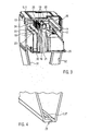
- FIG. 2 is the light 1 after FIG. 1 illustrated in a sectional view along a vertical section without pictograms, wherein in particular a corresponding inner housing 10 protrudes from the cut outer housing 2.
- the inner housing 10 may be formed as a one-piece injection molded part.
- the inner housing 10 has the Wasserabweis noticed 12, the interior of the outer housing 2 in a, s. also FIG. 3 , right-sided drying area and a left-sided wet area divided.
- the subdivision is carried out in particular by a discharge rib 14 as part of the water deflector 12.
- This discharge rib 14 is arranged substantially centrally in the inner housing 10 and points in the direction of the upper inner side 13 of the outer housing 2.
- the discharge rib 14 is substantially cut-shaped and serves for the deflection of optionally from the upper portion 11 of the connecting edge 5 in the direction of electronics 6 and / or light source 7 running water droplets. These can form moisture penetrated along the connecting edge, in particular in its upper section 11, on the upper inner side 13 of the outer housing 2.
- the drainage rib may be rectilinear in its upper end portion, but may also have a number of protrusions 35. These may point in the same or opposite directions.
- the discharge rib 14 is a final device of the water deflector 12 for deflecting water droplets. Further measures of the water deflector 12 for deflecting such water droplets are a first scraper rib 16 and a second scraper rib 17.
- the first scraper rib 16 is arranged at the smallest distance from the upper portion 11 of the connecting edge 5, while the second scraper rib 17 between the first scraper rib 16 and the discharge fin 14 is.
- Each wiper rib 16 and 17 is formed in a comb-like manner with a number of tongues 19 and gaps 18 arranged between them.
- the tongues 19 point in the direction of the upper inner side 13 of the outer housing 2 and serve as the first deflection measures for any droplets running along this upper inner side towards the dry area. Tongues and gaps between them can be formed with the same width or different width. This can apply to both wiper ribs 16 and 17, wherein tongues of the wiper ribs 16, 17 are arranged offset to one another.
- the arrangement of the tongues of the various wiper ribs 16 and 17 takes place in particular in such a way that a tongue 19 of the first wiper rib 16 is associated with a gap 18 of the second wiping rib 17 and vice versa. This results in a corresponding overlap of gaps and tongues both stripping ribs, which form a closed for corresponding to the upper inner side 13 of the outer casing 2 water droplets boundary.
- Drainage slopes 20, 21 are formed between the various ribs.
- a first drainage slope 20 is formed between the drainage rib 14 and the second stripper rib 17 and a second drainage slope 21 between the second stripper rib 17 and the first stripper rib 16.
- the drainage slopes 20, 21 extend from the discharge rib 14 inclined relative to the upper inner side 13 of the outer housing 2 downwards.
- the inclination of both drainage slopes 20, 21 is equal and the slope continues at lower ends 22 of the gaps 18. That is, the corresponding drainage slopes terminate flush with lower ends of the gaps 18.
- This drain surface 23 is at a greater distance 24 to the upper portion 11 of the outer edge 2 and the upper portion 11 of the connecting edge 5 arranged as a corresponding distance 25 from lower ends 22 of the gaps 18 in particular the first scraper rib 16th
- Such elements or components 6 include, for example, sockets for a light source, an electronic ballast, switching devices, lines or buses and the like.
- a light source for example, a light source, an electronic ballast, switching devices, lines or buses and the like.
- switching devices for example, switching devices, lines or buses and the like.
- the illuminant all conventional bulbs are used in the lamp according to the invention, such as fluorescent tube, LEDs, etc.
- Elements / components 6 and light sources 7 are in the outer housing 2, see in particular Figures 2 and 3 , disposed on a rear side 15 of the discharge rib 14, that is to say on a side of the discharge rib 14 pointing away from the upper portion 11 of the connecting edge 5.
- the drainage rib 14 can prevent a further flow of smallest water droplets or moisture in the direction of the drying area.
- the wedge shape of the side surfaces 8 of the outer housing 2 ensures that moisture or water collected from the wet area by the water deflector 12 flows to the lower end 34 of the outer housing 2.
- This lower end 34 is for example in FIG. 4 shown enlarged.
- latching or snap devices 28 for connection the housing parts 3 and 4 may be provided, wherein further such latching and snap devices 28 may also be provided at other locations along the connecting edge 5.
- the outer housing 2 is formed along its connecting edge in this area so that water collected there can escape via the connecting edge to the outside.
- this can take place in that the connection of the housing parts along the lower section 27 of the connecting edge 5 has leaks or else drainage devices in the form of openings or the like are formed at the lower end 34 of the outer housing 2
- the inner housing 10 For arranging the inner housing in the interior of the outer housing 2, the inner housing 10 has at its lower end 30 an at least partially encircling edge flange 29. This stands outwards and can from the top of the corresponding groove 33, see also the description regarding Figures 1 and 2 , rest. By this resting on the one hand, the inner housing 10 is disposed within the outer housing 2 and on the other hand, the corresponding abutment of the upper ends of the ribs on the upper inside or the corresponding spacing of these upper ends of the ribs set.
- a luminaire is described which, without additional sealing measures, meets the requirements for a luminaire with regard to a corresponding degree of protection. If necessary, penetrated moisture is safely collected and discharged and finally released from the outer casing of the lamp.
Landscapes
- Physics & Mathematics (AREA)
- General Physics & Mathematics (AREA)
- Engineering & Computer Science (AREA)
- Theoretical Computer Science (AREA)
- Business, Economics & Management (AREA)
- Emergency Management (AREA)
- Arrangement Of Elements, Cooling, Sealing, Or The Like Of Lighting Devices (AREA)
- Non-Portable Lighting Devices Or Systems Thereof (AREA)
Abstract
Description
- Die Erfindung betrifft eine Leuchte mit einem Außengehäuse und in dem Außengehäuse angeordneter Elektronik- und Leuchtmittel. Eine solche Leuchte ist beispielsweise eine Sicherheits- oder Rettungszeichenleuchte. Diese dienen innerhalb von Gebäuden zur Kennzeichnung von Fluchtwegen und weisen insbesondere zumindest ein Piktogramm auf einer Außenseite auf.
- Eine entsprechende Leuchte umfasst ein Außengehäuse aus zwei Gehäuseteilen, welche entlang einer im Wesentlichen umlaufenden Verbindungskante zusammengesetzt sind. Die entsprechende Elektronik der Leuchte umfasst je nach verwendetem Leuchtmittel, beispielsweise elektrische Anschlüsse, Taster, Schalter, ein elektronisches Vorschaltgerät und dergleichen. Ebenfalls werden zur Montage eines entsprechenden Leuchtmittels Fassungen für das jeweilige Leuchtmittel benötigt. Eine solche Leuchte kann für Dauerlicht und Bereitschaftslicht einsetzbar sein. Neben elektrischen Zuleitungen oder als Ersatz für diese sind auch Busleitungen verwendbar. Da entsprechende Leuchten auch als Batterieleuchten einsetzbar sind, kann zu der Elektronik auch eine entsprechende Batterie oder ein Akkumulator gehören. Weiterhin sind für solche Leuchten teilweise Statusanzeigen eines Fehlers, des Betriebs der Leuchte, und dergleichen verwendbar, die ebenfalls Teil der Elektronik sind. Eine solche Leuchte kann zur Decken- oder Wandmontage ausgebildet sein.
- Bei solchen Leuchten sind spezielle Schutzarten für die Eignung der Leuchte für verschiedene Umgebungsbedingungen vorgeschrieben, die zusätzlich auch den Menschen gegen potentielle Gefährdung bei deren Benutzung schützen. Insbesondere sollen solche Leuchten beständig gegen Feuchte, Wasser, Dämpfe oder dergleichen sein. Es besteht beispielsweise die Möglichkeit, dass solche Leuchten zusammen mit Brandschutzanlagen, wie Sprinklern und dergleichen, eingesetzt werden. Auch in einem solchen Fall sollen die Leuchten ihre Funktionsfähigkeit behalten, sodass diese beispielsweise gegen allseitiges Spritzwasser geschützt sind. Dies entspricht einer Schutzart nach IP-Code von IPX4. Solche Schutzarten ergeben sich beispielsweise durch verschiedene deutsche und internationale Normen, wie DIN EN 60529.
- Bisher wurde eine Leuchte der entsprechenden Schutzart dadurch realisiert, dass zwischen den entsprechenden Gehäuseteilen und insbesondere entlang der Verbindungskante eine Dichtung angeordnet wurde. Diese sollte das Eintreten von Wasser in das Außengehäuse verhindern. Nachteilig bei einer solchen Dichtung ist, dass das Gehäuse zur Anordnung und Aufnahme der Dichtung speziell bearbeitet werden muss, dass die Gehäuseteile mit angeordneter Dichtung genau einander zugeordnet werden müssen und die Dichtung ein zusätzliches Teil der Leuchte ist, das separat und genau angebracht werden muss und auch beim Zusammensetzen der Gehäuseteile zum Außengehäuse in keiner Weise beschädigt werden darf.
- Aufgabe vorliegender Erfindung ist, eine Leuchte der eingangs genannten Art dahingehen zu verbessern, dass diese auch dichtungsfrei für die entsprechende Schutzart einsetzbar ist.
- Diese Aufgabe wird durch die Merkmale des Patentanspruchs 1 gelöst, wobei insbesondere im Inneren des Außengehäuses ein Innengehäuse angeordnet ist, welches eine einseitig insbesondere zu einem oberen Abschnitt der Verbindungskante angeordnete Wasserabweiseinrichtung aufweist. Die Wasserabweiseinrichtung weist zumindest eine zur oberen Innenseite des Gehäuses vorstehende Abfließrippe auf. Auf einer von der Verbindungskante des Außengehäuses fortweisenden Rückseite der Abfließrippe sind Elektronik und/oder Leuchtmittel am Innengehäuse oder auch innerhalb des Außengehäuses angeordnet. Die Erfindung ist in gleicher Weise für Leuchten ohne transparente oder transluzente Seitenflächen einsetzbar.
- D. h. erfindungsgemäß werden die entsprechenden Gehäuseteile entlang ihrer Verbindungskante verbunden, ohne dass in diesem Bereich ein zusätzliches Dichtmittel oder dergleichen eingesetzt wird. Stattdessen wird entlang der Verbindungskante insbesondere durch eine im Wesentlichen nur formschlüssige Verbindung das Außengehäuse aus den Gehäuseteilen zusammengesetzt, wobei ein gewisses Maß an Feuchtigkeit in das Außengehäuse eindringen darf. Die entsprechende Feuchtigkeit kann innerhalb des Außengehäuses kleine Tröpfchen bilden, die auf der Innenseite des Außengehäuses ablaufen können. Um zu verhindern, dass solche Tröpfchen in den Bereich der Elektronik und des Leuchtmittels gelangen, ist das Innengehäuse mit Wasserabweiseinrichtung vorgesehen. Entsprechende Wassertröpfchen würden entlang flacher Innenseiten des Außengehäuses laufen und mit insbesondere der Abfließrippe der Wasserabweiseinrichtung in Kontakt geraten. Entlang der Abfließrippe werden solche Tröpfchen von der Innenseite des Außengehäuses ablaufen, sodass sie an einem Kontakt mit der Elektronik und dem Leuchtmittel gehindert sind. Durch die Wasserabweiseinrichtung und insbesondere die zumindest eine Abfließrippe wird das Außengehäuse im Wesentlichen in einen "Feuchtbereich" und einen "Trockenbereich" unterteilt. Im Trockenbereich sind Elektronik und Leuchtmittel angeordnet. Der Feuchtbereich dient zum Sammeln einer gegebenenfalls eingedrungenen Feuchtigkeit und zur Aufnahme von der Abfließrippe aufgenommener und abgelenkter Wassertröpfchen.
- Um die Unterteilung in Trocken- und Feuchtbereich weiter zu verbessern, kann die Wasserabweiseinrichtung zusätzlich wenigstens zwei kammartige, zwischen oberem Abschnitt der Verbindungskante und der Abfließrippe angeordnete erste und zweite Abstreifrippen aufweisen. Diese dienen als erste Maßnahmen zum Ablenken entsprechender Tröpfchen, die sich entlang der oberen Innenseite des Außengehäuses in Richtung Elektronik oder Leuchtmittel bewegen. Die Abfließrippe dient in diesem Zusammenhang als im Wesentlichen letzte Maßnahme zur Tröpfchenablenkung.
- Durch Abfließrippe und die erste und die zweite Abstreifrippe ergeben sich auf diese Weise drei Feuchtigkeitsschutzeinrichtungen der Wasserabweiseinrichtungen, die hintereinander in Richtung zum Trockenbereich angeordnet sind.
- In diesem Zusammenhang kann es sich als günstig erweisen, wenn die erste und die zweite Abstreifrippe eine Reihe von durch Lücken beabstandete Zungen aufweist, die in Richtung oberer Innenseite des Außengehäuses vorstehen. Entsprechende Tröpfchen werden durch die Zungen aufgefangen und können dann durch die Lücken zwischen den Zungen ablaufen.
- Ein solches Auffangen von Tröpfchen und Lenken derselben in Richtung Feuchtbereich kann dadurch verbessert werden, wenn die Zungen bzw. Lücken der ersten und zweiten Abstreifrippe versetzt zueinander angeordnet sind. D. h., dass Tröpfchen die gegebenenfalls durch Zungen der ersten Abstreifrippe noch nicht abgefangen und abgelenkt werden, mit hoher Wahrscheinlichkeit durch die Zungen der zweiten Abstreifrippe abgefangen und abgelenkt werden. Die dritte Rippe (Abfließrippe) dient vorrangig dazu, dass bereits herabgelaufene Tropfen nicht in den Trockenbereich gelangen, sondern durch die Lücken zwischen den Zungen zum Feuchtbereich ablaufen. In diesem Zusammenhang kann es weiterhin als günstig betrachtet werden, wenn die Zungen der ersten Abstreifrippe den Lücken der zweiten Abstreifrippe zugeordnet sind und umgekehrt. D. h., dass die entsprechenden Abstreifrippen mit Zungen und Lücken so versetzt zueinander angeordnet sind, dass Zungen der ersten Abstreifrippe Lücken der zweiten Abstreifrippe überdecken und umgekehrt. Zungen und Lücken in einer und auch in beiden Abstreifrippen können mit unterschiedlichen Breiten ausgebildet sein.
- Dadurch ist in hohem Maße sichergestellt, dass bereits die Zungen von erster und zweiter Abstreifrippe alle gegebenenfalls entlang der oberen Innenseite der Abdeckung sich bewegende Tröpfchen auffangen und ablenken.
- Außerdem ist sichergestellt, dass bereits abgelenkte Tröpfchen in einfacher Weise durch die Lücken von erster und zweiter Abstreifrippe in Richtung Feuchtgebiet ablaufen können.
- Um ein entsprechendes Ablaufen der bereits abgelenkten Wassertröpfchen vorteilhaft zu unterstützen, können zwischen Abfließrippe und zweiter Abstreifrippe und/oder zwischen zweiter Abstreifrippe und erster Abstreifrippe sich relativ zur oberen Innenseite des Außengehäuses nach unten geneigte Ablaufschrägen ausgebildet sein. Die entsprechende Neigung der Ablaufschrägen verläuft dabei in der Weise, dass eine Neigung nach unten von Abfließrippe zur zweiten Abstreifrippe und von der zweiten Abstreifrippe zur ersten Abstreifrippe vorliegt.
- Da die entsprechenden Ablaufschrägen in Richtung der Lücken verlaufen, kann es sich in diesem Zusammenhang weiterhin als Vorteil erweisen, wenn die Ablaufschrägen jeweils im Wesentlichen bündig zu unteren Enden der Lücken jeweils von erster oder zweiter Abstreifrippe enden. D. h., es ist keine Stufe zwischen Ablaufschräge und unteren Enden der Lücken gebildet. Stattdessen können Tröpfchen ungehindert von der Ablaufschräge durch die Lücken weiterlaufen.
- Es besteht die Möglichkeit, dass die Ablaufschrägen unterschiedliche Neigungen aufweisen. Beispielsweise könnte die Ablaufschräge zwischen Abfließrippe und zweiter Abstreifrippe eine höhere Neigung als die Ablaufschräge zwischen zweiter Abstreifrippe und erster Abstreifrippe aufweisen. Dies ist darin begründet, dass beispielsweise mehr Wassertröpfchen in der Regel zur Ablaufschräge zwischen zweiter Abstreifrippe und erster Abstreifrippe gelangen, da in diesem Bereich zusätzlich Wassertröpfchen auftreten können, die bereits durch Abfließrippe und zweite Abstreifrippe abgelenkt wurden. Allerdings besteht ebenfalls die Möglichkeit, dass beide Ablaufschrägen die gleiche Neigung aufweisen. Dadurch ergibt sich eine einfachere Herstellung der Ablaufschrägen und eine insgesamt mit gleicher Neigung ausgebildete Gesamtablaufschräge, die durch entsprechende untere Enden der Lücken ergänzt ist.
- D. h., es besteht ebenfalls die Möglichkeit, dass untere Enden der Lücken entsprechend zur jeweiligen Ablaufschräge geneigt ausgebildet sind. Dies bedeutet außerdem, dass untere Enden der Lücken der ersten Abstreifrippe in der Regel in größerem Abstand zur oberen Innenseite des Außengehäuses angeordnet sind als untere Enden der Lücken der zweiten Abstreifrippe.
- Um zu verhindern, dass beispielsweise direkt Wassertröpfchen von dem oberen Abschnitt der Verbindungskante bis zum unteren Ende des Außengehäuses herunterfallen können, kann im Wesentlichen unterhalb des oberen Abschnitts der Verbindungskante eine Ablauffläche des Innengehäuses ausgebildet sein, welche insbesondere mit größerem Abstand zu diesem oberen Abschnitt der Verbindungskante als untere Enden der Lücken in der ersten Abstreifrippe angeordnet ist. Diese Ablauffläche dient nicht nur zum Auffangen direkt herunterfallender Wassertropfen, sondern ebenfalls zur Aufnahme von über die Ablaufschräge zugeführten Wassertröpfchen. Die Ablauffläche kann weiterhin so ausgebildet sein, dass sie entsprechende Wassertröpfchen oder angesammelte Feuchtigkeit in einer bestimmten Richtung innerhalb des Außengehäuses führt und diese schließlich einer Stelle des Außengehäuses zuführt, wo die entsprechende Feuchtigkeit nach außen austreten kann.
- Zur Versorgung der Leuchte sind in der Regel entsprechende Anschlüsse oder Zuleitungen notwendig, die von Außen an die Leuchte und insbesondere das Außengehäuse herangeführt werden. Im Zusammenhang mit den vorangehenden Merkmalen ist es dabei gegebenenfalls von Vorteil, wenn elektrische Anschlüsse und/oder Zuleitungen am Außengehäuse rückseitig zur Abfließrippe angeordnet sind. Auf diese Weise befinden sich ebenfalls die den elektrischen Anschlüssen oder Zuleitungen am Außengehäuse zugeordneten Einrichtungen im Trockenbereich.
- Das Innengehäuse ist mit verschiedenen Einrichtungen sowohl zur Halterung der elektrischen Einrichtungen und Leuchtmittel sowie auch mit den entsprechenden Teilen der Wasserabweiseinrichtung ausgebildet. Ein vereinfachter Aufbau und ein einfaches Einsetzen des Innengehäuses kann sich dadurch ergeben, wenn dieses einteilig hergestellt ist. Das Innengehäuse kann beispielsweise als Spritzgussteil hergestellt sein. Es ist einfach in das Außengehäuse einsetzbar, wobei innerhalb des Außengehäuses entsprechende Aufnahmeeinrichtungen zur Anordnung und Halterung des Innengehäuses vorgesehen sein können.
- Um die im Feuchtbereich gesammelte Feuchtigkeit oder entsprechendes Wasser nach Außen relativ zum Außengehäuse abführen zu können, kann zumindest ein unterer Abschnitt der Verbindungskante der Gehäuseteile feuchtigkeits- bzw. wasserdurchlässig ausgebildet sein. Dies kann beispielsweise in einfacher Weise dadurch erfolgen, dass in einem Bodenbereich des Außengehäuses die entsprechende Verbindungskante so ausgebildet ist, dass Feuchtigkeit und/oder Wasser austreten kann oder in diesem Bereich Feuchtigkeits- und/oder Wasseraustrittsöffnungen vorgesehen sind.
- Durch Ausbildung der entsprechenden Gehäuseteile mit Verbindungskante ist es ebenfalls in einfacher Weise möglich, die Gehäuseteile miteinander zu verbinden. Eine Möglichkeit einer solchen Verbindung ist eine Verrastung oder ein Verschnappen oder dergleichen. Es kann eine entsprechende Anzahl von Rast- und Schnappeinrichtungen vorgesehen sein.
- Um das Innengehäuse gegebenenfalls in einfacher Weise innerhalb des Außengehäuses anordnen und in einer entsprechender Einbaustellung halten zu können, kann das Innengehäuse zumindest einen teilweise entlang eines unteren Endes umlaufenden Randflansch aufweisen, welcher mit einer Innenseite des Außengehäuses in Anlage ist. An entsprechender Stelle der Innenseite des Außengehäuses kann ein nach innen weisender Vorsprung zum Auflegen des umlaufenden Randflansches ausgebildet sein. Es besteht ebenfalls die Möglichkeit, dass bei einem sich keilförmig nach unten verengenden Außengehäuses eine entsprechende Anlage mit einer Innenseite des Außengehäuses allein durch die entsprechende Keilform auftritt.
- Um einen teilweisen Formschluss entlang der Verbindungskante zu ermöglichen, kann die Verbindungskante zumindest stellenweise stufenförmig ausgebildet sein. Eine entsprechende Stufenform kann von beiden Gehäuseteilen des Außengehäuses vorgegeben sein, wobei die entsprechenden Stufen ineinandergreifen. Andere formschlüssige Verbindungen entlang der Verbindungskante sind selbstverständlich möglich.
- Im Folgenden wird ein vorteilhaftes Ausführungsbeispiel der Erfindung anhand der in der Zeichnung beigefügten Figuren näher erläutert.
- Es zeigen:
- Figur 1
- eine perspektivische Seitenansicht eines Ausführungsbeispiels einer erfindungsgemäßen Leuchte;
- Figur 2
- die Leuchte nach
Figur 1 ohne Piktogramm und in einem Vertikalschnitt mit Innengehäuse; - Figur 3
- einen Schnitt analog zu
Figur 2 in Vergrößerter Darstellung und - Figur 4
- einen Schnitt analog zu
Figur 2 für einen unteren Bereich des Außengehäuses in vergrößerter Darstellung -
Figur 1 zeigt eine perspektivische Ansicht von einer rechten Seite her einer erfindungsgemäßen Leuchte 1. Die Leuchte 1 ist als Sicherheits- oder Rettungszeichenleuchte ausgebildet. Diese weist ein Außengehäuse 2 auf, welches aus zwei Gehäuseteilen 3 und 4 zusammengesetzt ist. Die beiden Gehäuseteile 3 und 4 sind entlang einer Verbindungskante 5 in Kontakt und miteinander verbunden. Ein oberer Teil des Außengehäuses ist im Wesentlichen quaderförmig aufgebaut, während ein unterer Teil keilförmig nach unten zuläuft. Dieser untere Teil weist Seitenflächen 8 auf, die transparent oder transluzent ausgebildet sind. Auf den Seitenflächen 8 sind Piktogramme 9 angeordnet, die einen Fluchtweg kennzeichnen. Ein solches Piktogramm kann beispielsweise als selbstklebende Folie aufgebracht sein. - Zwischen unterem keilförmigen Teil und oberem quaderförmigen Teil läuft ein zum Inneren des Außengehäuses eingeprägte Nut um. Auf einer Oberseite des Außengehäuses ist eine Vertiefung angebracht, in der Anschlüsse 26 für elektrische Zuleitungen oder dergleichen anordbar sind.
- Die entsprechende Verbindungskante 5 ist außermittig und versetzt zu einer Seitenfläche 8 des Außengehäuses 2 angeordnet. Die Verbindungskante 5 weist einen oberen Abschnitt 11 auf, der im Folgenden im Zusammenhang mit einer Wasserabweiseinrichtung 12 weiter beschrieben wird.
- An einem unteren Ende 34 ist ein unterer Abschnitt der Verbindungskante ausgebildet, s. auch
Figuren 2 und4 . - In
Figur 2 ist die Leuchte 1 nachFigur 1 in einer geschnittenen Darstellung entlang eines Vertikalschnitts ohne Piktogramme dargestellt, wobei insbesondere ein entsprechendes Innengehäuse 10 aus dem geschnittenen Außengehäuse 2 vorsteht. Das Innengehäuse 10 kann als einteiliges Spritzgussteil ausgebildet sein. Das Innengehäuse 10 weist die Wasserabweiseinrichtung 12 auf, die den Innenraum des Außengehäuses 2 in einen, s. auchFigur 3 , rechtsseitigen Trockenbereich und einen linksseitigen Feuchtbereich unterteilt. Die Unterteilung erfolgt insbesondere durch eine Abfließrippe 14 als Teil der Wasserabweiseinrichtung 12. Diese Abfließrippe 14 ist im Wesentlichen mittig im Innengehäuse 10 angeordnet und weist in Richtung zur oberen Innenseite 13 des Außengehäuses 2. Die Abfließrippe 14 ist im Wesentlichen schneidenförmig ausgebildet und dient zur Ablenkung von gegebenenfalls von dem oberen Abschnitt 11 der Verbindungskante 5 in Richtung Elektronik 6 und/oder Leuchtmittel 7 laufenden Wassertröpfchen. Diese können sich durch entlang der Verbindungskante insbesondere in deren oberem Abschnitt 11 eingedrungene Feuchtigkeit auf der oberen Innenseite 13 des Außengehäuses 2 bilden. Die Abfließrippe kann in ihrem oberen Endabschnitt geradlinig verlaufen, kann aber auch eine Anzahl von Ausbuchtungen 35 aufweisen. Diese können in dieselbe oder auch entgegengesetzte Richtungen weisen. - Die Abfließrippe 14 ist eine letzte Einrichtung der Wasserabweiseinrichtung 12 zur Ablenkung von Wassertröpfchen. Weitere Maßnahmen der Wasserabweiseinrichtung 12 zur Ablenkung solcher Wassertröpfchen sind ein erste Abstreifrippe 16 und eine zweite Abstreifrippe 17. Die erste Abstreifrippe 16 ist in geringstem Abstand zum oberen Abschnitt 11 der Verbindungskante 5 angeordnet, während die zweite Abstreifrippe 17 zwischen erster Abstreifrippe 16 und Abfließrippe 14 angeordnet ist. Jede Abstreifrippe 16 und 17 ist kammartig mit einer Anzahl von Zungen 19 und zwischen diesen angeordneten Lücken 18 ausgebildet. Die Zungen 19 weisen in Richtung der oberen Innenseite 13 des Außengehäuses 2 und dienen als erste Ablenkmaßnahmen für gegebenenfalls entlang dieser oberen Innenseite in Richtung Trockenbereich laufende Tröpfchen. Zungen und Lücken zwischen diesen können mit jeweils gleicher Breite oder unterschiedlicher Breite ausgebildet sein. Dies kann für beide Abstreifrippen 16 und 17 gelten, wobei Zungen der Abstreifrippen 16, 17 versetzt zueinander angeordnet sind.
- Die Anordnung der Zungen der verschiednen Abstreifrippen 16 und 17 erfolgt insbesondere in der Weise, dass eine Zunge 19 der ersten Abstreifrippe 16 einer Lücke 18 der zweiten Abstreifrippe 17 und umgekehrt zugeordnet ist. Dadurch ergibt sich ein entsprechender Überlapp von Lücken und Zungen beide Abstreifrippen, die eine für entsprechend der oberen Innenseite 13 des Außengehäuses 2 ablaufende Wassertröpfchen geschlossene Begrenzung bilden.
- Zwischen den verschiedenen Rippen sind Ablaufschrägen 20, 21 ausgebildet. Eine erste Ablaufschräge 20 ist zwischen der Abfließrippe 14 und der zweiten Abstreifrippe 17 und eine zweite Ablaufschräge 21 zwischen der zweiten Abstreifrippe 17 und der ersten Abstreifrippe 16 gebildet. Die Ablaufschrägen 20, 21 verlaufen von der Abfließrippe 14 relativ zur oberen Innenseite 13 des Außengehäuses 2 nach unten geneigt. Die Neigung beider Ablaufschrägen 20, 21 ist gleich und die Schräge setzt sich an unteren Enden 22 der Lücken 18 fort. D. h., die entsprechenden Ablaufschrägen enden bündig zu unteren Enden der Lücken 18.
- Über die Ablaufschrägen läuft von der Abfließrippe 14 bzw. den Abstreifrippen 16, 17 abgelenkte Feuchtigkeit bzw. abgelenkte Wassertröpfchen weg vom Trockenbereich in Richtung einer Ablauffläche 23 als weiterer Teil der Wasserabweiseinrichtung 12 bzw. des Innengehäuses 10. Diese Ablauffläche 23 ist in größerem Abstand 24 zur oberen Innenseite 13 des Außengehäuses 2 bzw. zum oberen Abschnitt 11 der Verbindungskante 5 angeordnet wie ein entsprechender Abstand 25 von unteren Enden 22 der Lücken 18 insbesondere der ersten Abstreifrippe 16.
- In diesem Zusammenhang sei angemerkt, dass untere Enden der Lücken 18 der zweiten Abstreifrippe 17 in geringerem Abstand zur oberen Innenseite als entsprechend untere Enden 22 der Lücken 18 der ersten Abstreifrippe 16 angeordnet sind. Dies ergibt sich durch die Ablaufschrägen 20, 21, die entsprechend durch untere Enden der Lücken 18 fortgesetzt sind.
- Von der Ablauffläche 23 gelangt gesammelte Feuchtigkeit bzw. Wasser in einen unteren Bereich des Außengehäuses, wobei entsprechende Feuchtigkeit bzw. Wasser entlang von Innenseite 31 des Außengehäuses ablaufen kann, Innenseite 32 ist im wesentlichen Teil des Trockenbereichs. Schließlich gelangt entsprechendes Wasser zum unteren Ende 34 des Außengehäuses und kann dort entlang eines unteren Abschnitts 27 der Verbindungskante 5 austreten. Ein solches Austreten kann dadurch erfolgen, dass die Verbindungskante der Gehäuseteile 3, 4 entsprechend undicht ausgebildet ist bzw. separate Abflusseinrichtungen am unteren Ende 34 des Außengehäuses vorgesehen sind.
- Entsprechende stromführende Elemente oder Bauteile 6 bzw. Leuchtmittel 7 sind in den beigefügten Figuren nicht im Detail dargestellt. Zu solchen Elementen oder Bauteilen 6 gehören beispielsweise Fassungen für ein Leuchtmittel, ein elektronisches Vorschaltgerät, Schalteinrichtungen, Leitungen oder Busse und dergleichen. Als Leuchtmittel sind bei der erfindungsgemäßen Leuchte alle üblichen Leuchtmittel verwendbar, wie Leuchtstoffröhre, LEDs, usw.
- Elemente/Bauteile 6 und Leuchtmittel 7 sind in dem Außengehäuse 2, siehe insbesondere
Figuren 2 und3 , auf einer Rückseite 15 der Abfließrippe 14 angeordnet, das heißt auf einer von dem oberen Abschnitt 11 der Verbindungskante 5 fortweisenden Seite der Abfließrippe 14. - Es sei weiterhin angemerkt an dieser Stelle, dass entsprechende obere Enden von Abfließrippe 14 und Abstreifrippen 16 und 17 mit der oberen Innenseite 13 des Außengehäuses 2 in Anlage oder zumindest so gering von dieser oberen Innenseite beabstandet sind, dass gebildete Wassertröpfchen abgefangen und abgelenkt werden. Dabei besteht die Möglichkeit, dass beispielsweise ein Abstand von oberen Enden der entsprechenden Rippen zur oberen Innenseite unterschiedlich ist, wobei dieser Abstand von der ersten Abstreifrippe 16 bis zur Abfließrippe 14 abnehmen kann.
- Dadurch werden durch die Abstreifrippe 16 die größten Wassertröpfchen und von der zweiten Abstreifrippe 17 kleinere Wassertröpfchen aufgenommen und abgelenkt. Die Abfließrippe 14 kann als letzte Maßnahme der Wasserabweiseinrichtung 12 ein Weiterfließen von kleinsten Wassertröpfchen oder Feuchtigkeit in Richtung Trockenbereich verhindern.
- Durch die Keilform der Seitenflächen 8 des Außengehäuses 2 wird sichergestellt, dass aus dem Feuchtbereich durch die Wasserabweiseinrichtung 12 gesammelte Feuchtigkeit oder Wasser zum unteren Ende 34 des Außengehäuses 2 fließt. Dies untere Ende 34 ist beispielsweise in
Figur 4 vergrößert dargestellt. An diesem unteren Ende 34 des Außengehäuses 2 befindet sich ein unterer Abschnitt 27 der Verbindungskante 5. Weiterhin können in diesem Bereich entsprechende Rast- oder Schnappeinrichtungen 28 zur Verbindung der Gehäuseteile 3 und 4 vorgesehen sein, wobei weitere solcher Rast- und Schnappeinrichtungen 28 auch an weiteren Stellen entlang der Verbindungskante 5 vorgesehen sein können. - Dabei ist das Außengehäuse 2 entlang seiner Verbindungskante in diesem Bereich so ausgebildet, dass dort gesammeltes Wasser über die Verbindungskante nach Außen austreten kann. Dies kann einerseits dadurch erfolgen, dass die Verbindung der Gehäuseteile entlang des unteren Abschnitts 27 der Verbindungskante 5 Undichtigkeiten aufweist oder auch Abflusseinrichtungen in Form von Öffnungen oder dergleichen am unteren Ende 34 des Außengehäuses 2 ausgebildet sind
- Zur Anordnung des Innengehäuses im Inneren des Außengehäuses 2 weist das Innengehäuse 10 an seinem unteren Ende 30 einen zumindest teilweise umlaufenden Randflansch 29 auf. Dieser steht nach außen ab und kann von oben auf der entsprechenden Nut 33, siehe auch die Beschreibung hinsichtlich
Figuren 1 und 2 , aufliegen. Durch dieses Aufliegen wird einerseits das Innengehäuse 10 innerhalb des Außengehäuses 2 angeordnet und andererseits die entsprechende Anlage der oberen Enden der Rippen an oberer Innenseite oder die entsprechende Beabstandung dieser oberen Enden der Rippen festgelegt. - Erfindungsgemäß wird eine Leuchte beschrieben, die ohne zusätzliche Dichtmaßnahmen, Anforderungen an eine Leuchte bezüglich einer entsprechenden Schutzart genügt. Gegebenenfalls eingedrungene Feuchtigkeit wird sicher aufgefangen und abgeleitet und schließlich aus dem Außengehäuse der Leuchte abgegeben.
Claims (16)
- Leuchte (1), insbesondere Sicherheits- oder Rettungszeichenleuchte, mit einem aus zwei Gehäuseteilen (3, 4) im Wesentlichen entlang einer umlaufenden Verbindungskante (5) zusammengesetzten Außengehäuse (2), innerhalb des Außengehäuses angeordneter Elektronik (6) und Leuchtmittel (7), wobei das Außengehäuse (2), insbesondere seitliche transparente oder transluzente Seitenflächen (8) aufweist, welchen beispielsweise ein Piktogramm (9) zugeordnet ist, dadurch gekennzeichnet, dass innerhalb des Außengehäuses (2) ein Innengehäuse (10) angeordnet ist, welches eine einseitig insbesondere zu einem oberen Abschnitt (11) der Verbindungskante (5) angeordnete Wasserabweiseinrichtung (12) aufweist, welche zumindest eine zur oberen Innenseite (13) des Außengehäuses (2) vorstehende Abfließrippe (14) aufweist, wobei auf einer von der Verbindungskante (5) des Außengehäuses (2) fortweisenden Rückseite (15) der Abfließrippen (14) stromführende Elemente oder Bauteile (6) und/oder Leuchtmittel (7) am Innengehäuse (10) angeordnet sind.
- Leuchte nach Anspruch 1, dadurch gekennzeichnet, dass die Wasserabweiseinrichtung (12) wenigstens zwei kammartige, zwischen oberem Abschnitt (11) der Verbindungskante (5) und der Abfließrippe (14) angeordnete erste und zweite Abstreifrippen (16, 17) aufweist.
- Leuchte nach Anspruch 1 oder 2, dadurch gekennzeichnet, dass jede Abstreifrippe (16, 17) eine Reihe von durch Lücken (18) beabstandete Zungen (19) aufweist, die in Richtung oberer Gehäuseinnenseite (13) vorstehen.
- Leuchte nach einem der vorangehenden Ansprüche, dadurch gekennzeichnet, dass die Zungen (19) bzw. Lücken (18) der ersten und zweiten Abstreifrippe (16, 17) versetzt zueinander angeordnet sind.
- Leuchte nach einem der vorangehenden Ansprüche, dadurch gekennzeichnet, dass die Zungen (19) der ersten Abstreifrippe (16) den Lücken (18) der zweiten Abstreifrippe (17) zugeordnet sind.
- Leuchte nach einem der vorangehenden Ansprüche, dadurch gekennzeichnet, dass zwischen Abfließrippe (14) und zweiter Abstreifrippe (17) und/oder zwischen zweiter Abstreifrippe (17) und erster Abstreifrippe (16) eine relativ zur oberen Gehäuseinnenseite (13) nach unten geneigte Ablaufschräge (20, 21) ausgebildet ist.
- Leuchte nach einem der vorangehenden Ansprüche, dadurch gekennzeichnet, dass die Ablaufschrägen (20, 21) im Wesentlichen bündig zu unteren Enden (22) der Lücken (18) von jeweils erster oder zweiter Abstreifrippe (16, 17) enden.
- Leuchte nach einem der vorangehenden Ansprüche, dadurch gekennzeichnet, dass die Ablaufschrägen (20, 21) die gleiche Neigung aufweisen.
- Leuchte nach einem der vorangehenden Ansprüche, dadurch gekennzeichnet, dass untere Enden (22) der Lücken (18) entsprechend zur Ablaufschräge (20, 21) geneigt ausgebildet sind.
- Leuchte nach einem der vorangehenden Ansprüche, dadurch gekennzeichnet, dass insbesondere unterhalb des oberen Abschnitts (11) der Verbindungskante (5) eine Ablauffläche (23) des Innengehäuses (10) ausgebildet ist, welche mit größerem Abstand (24) zu dem oberen Abschnitt (11) der Verbindungskante (5) als untere Enden der Lücken (18) in erster oder zweiter Abstreifrippe (16, 17) angeordnet sind.
- Leuchte nach einem der vorangehenden Ansprüche, dadurch gekennzeichnet, dass elektrische Anschlüsse oder Zuleitungen (26) am Außengehäuse (2) rückseitig zur Abfließrippe (14) angeordnet sind.
- Leuchte nach einem der vorangehenden Ansprüche, dadurch gekennzeichnet, dass das Innengehäuse (10) einteilig hergestellt ist.
- Leuchte nach einem der vorangehenden Ansprüche, dadurch gekennzeichnet, dass zumindest ein unterer Abschnitt (27) der Verbindungskante (5) der Gehäuseteil (3, 4) feuchtigkeits- bzw. wasserdurchlässig ausgebildet ist.
- Leuchte nach einem der vorangehenden Ansprüche, dadurch gekennzeichnet, dass die Gehäuseteile (3, 4) miteinander verrastbar sind.
- Leuchte nach einem der vorangehenden Ansprüche, dadurch gekennzeichnet, dass das Innengehäuse (10) zumindest teilweise einen entlang einem unteren Ende (30) umlaufenden Randflansch (29) aufweist, welcher mit einer Innenseite (31, 32) des Außengehäuses (2) in Anlage ist.
- Leuchte nach einem der vorangehenden Ansprüche, dadurch gekennzeichnet, dass die Verbindungskante (5) zumindest stellenweise stufenförmig ausgebildet ist.
Priority Applications (1)
| Application Number | Priority Date | Filing Date | Title |
|---|---|---|---|
| PL13003152T PL2709087T3 (pl) | 2012-09-13 | 2013-06-20 | Oprawa oświetleniowa |
Applications Claiming Priority (1)
| Application Number | Priority Date | Filing Date | Title |
|---|---|---|---|
| DE202012008802.5U DE202012008802U1 (de) | 2012-09-13 | 2012-09-13 | Leuchte |
Publications (3)
| Publication Number | Publication Date |
|---|---|
| EP2709087A2 true EP2709087A2 (de) | 2014-03-19 |
| EP2709087A3 EP2709087A3 (de) | 2014-10-15 |
| EP2709087B1 EP2709087B1 (de) | 2018-10-24 |
Family
ID=48745589
Family Applications (1)
| Application Number | Title | Priority Date | Filing Date |
|---|---|---|---|
| EP13003152.9A Active EP2709087B1 (de) | 2012-09-13 | 2013-06-20 | Leuchte |
Country Status (4)
| Country | Link |
|---|---|
| EP (1) | EP2709087B1 (de) |
| DE (1) | DE202012008802U1 (de) |
| ES (1) | ES2698057T3 (de) |
| PL (1) | PL2709087T3 (de) |
Families Citing this family (1)
| Publication number | Priority date | Publication date | Assignee | Title |
|---|---|---|---|---|
| DE202024100267U1 (de) * | 2024-01-19 | 2025-04-23 | Zumtobel Lighting Gmbh | Sicherheitszeichenleuchte |
Family Cites Families (5)
| Publication number | Priority date | Publication date | Assignee | Title |
|---|---|---|---|---|
| DE29815480U1 (de) * | 1998-08-28 | 2000-01-05 | CEAG Sicherheitstechnik GmbH, 59494 Soest | Bausatz für Leuchten |
| US7308987B2 (en) * | 2004-12-22 | 2007-12-18 | Behr Process Corporation | Modular display apparatus |
| TW201024607A (en) * | 2008-12-19 | 2010-07-01 | Crownmate Technology Co Ltd | Thin LED lamp structure |
| DE102009060607B4 (de) * | 2009-12-23 | 2015-10-29 | Rp-Technik Gmbh | Rettungszeichenleuchte mit erhöhter Lichtausbeute |
| DE102010014614B4 (de) * | 2010-04-10 | 2012-02-09 | Ropag High-Tech | Scheibenleuchte |
-
2012
- 2012-09-13 DE DE202012008802.5U patent/DE202012008802U1/de not_active Expired - Lifetime
-
2013
- 2013-06-20 PL PL13003152T patent/PL2709087T3/pl unknown
- 2013-06-20 ES ES13003152T patent/ES2698057T3/es active Active
- 2013-06-20 EP EP13003152.9A patent/EP2709087B1/de active Active
Non-Patent Citations (1)
| Title |
|---|
| None |
Also Published As
| Publication number | Publication date |
|---|---|
| EP2709087B1 (de) | 2018-10-24 |
| EP2709087A3 (de) | 2014-10-15 |
| DE202012008802U1 (de) | 2014-01-09 |
| PL2709087T3 (pl) | 2019-05-31 |
| ES2698057T3 (es) | 2019-01-30 |
Similar Documents
| Publication | Publication Date | Title |
|---|---|---|
| EP2091111B1 (de) | Kontaktierungssystem für Lichtbänder oder Leuchten | |
| AT516205B1 (de) | Leuchte für ein Lichtbandsystem | |
| EP0113809A2 (de) | Elektrischer Steckverbinder mit einer Verriegelungseinrichtung für ein in einer Gehäusekammer steckendes, elektrisches Kontaktelement | |
| EP2911141B1 (de) | Leuchte | |
| EP3137810B1 (de) | Abdeckung für die trägeranordnung eines lichtbandsystems, sowie lichtbandsystem | |
| DE102016103439B4 (de) | Kontaktstelle eines Flachleiters | |
| EP2886946A1 (de) | Halter für eine Betriebskomponente einer Leuchte | |
| DE102019109638A1 (de) | Schaltschrankanordnung mit einem Schaltschrankrahmengestell und einem auf einer Montageplatte montierten mehrpoligen Berührungsschutzmodul | |
| EP2709087B1 (de) | Leuchte | |
| DE10355900B3 (de) | Beleuchtungseinrichtung in einem als Entwässerungsrinne ausgebildeten Aufnahmekörper | |
| DE102014103575B4 (de) | Vorrichtung zum Schutz gegen Überspannungen | |
| DE102010001411B4 (de) | Gehäuse für eine elektrische Schaltung | |
| EP2994694B1 (de) | Plattenförmiges reflektorelement für led-platine | |
| DE3906366A1 (de) | Lampenfassung fuer kraftfahrzeuge | |
| EP2561580B1 (de) | Leistungsschalter in Federzugtechnik | |
| EP0654877B1 (de) | Schaltschrank mit Lüftungsöffnungen | |
| DE10336429B4 (de) | Spritzwassergeschütztes, elektrisches Aufputz-Installationsgerät | |
| EP0654634A1 (de) | Leuchte für Leuchtstoffröhren | |
| DE102010053507B4 (de) | Installationsschaltgerät mit einer Lichtbogenlöscheinrichtung | |
| WO2006042694A1 (de) | Entwässerungsrinne | |
| DE102015115179A1 (de) | Vorrichtung zur Belüftung einer Garage | |
| DE102017112011A1 (de) | Rahmen für ein Photovoltaik-Modul sowie Photovoltaik-System | |
| DE102005047045B3 (de) | Anschlussadapter | |
| DE102006060231B4 (de) | Elektrisches/elektronisches Installationsgerät | |
| WO2014183957A1 (de) | Begrenster druckentlastungsklappe für elektrische anlage, insbesondere mittelspannungsschaltanlage |
Legal Events
| Date | Code | Title | Description |
|---|---|---|---|
| PUAI | Public reference made under article 153(3) epc to a published international application that has entered the european phase |
Free format text: ORIGINAL CODE: 0009012 |
|
| AK | Designated contracting states |
Kind code of ref document: A2 Designated state(s): AL AT BE BG CH CY CZ DE DK EE ES FI FR GB GR HR HU IE IS IT LI LT LU LV MC MK MT NL NO PL PT RO RS SE SI SK SM TR |
|
| AX | Request for extension of the european patent |
Extension state: BA ME |
|
| PUAL | Search report despatched |
Free format text: ORIGINAL CODE: 0009013 |
|
| AK | Designated contracting states |
Kind code of ref document: A3 Designated state(s): AL AT BE BG CH CY CZ DE DK EE ES FI FR GB GR HR HU IE IS IT LI LT LU LV MC MK MT NL NO PL PT RO RS SE SI SK SM TR |
|
| AX | Request for extension of the european patent |
Extension state: BA ME |
|
| 17P | Request for examination filed |
Effective date: 20150225 |
|
| RBV | Designated contracting states (corrected) |
Designated state(s): AL AT BE BG CH CY CZ DE DK EE ES FI FR GB GR HR HU IE IS IT LI LT LU LV MC MK MT NL NO PL PT RO RS SE SI SK SM TR |
|
| 17Q | First examination report despatched |
Effective date: 20150723 |
|
| RIC1 | Information provided on ipc code assigned before grant |
Ipc: G09F 13/04 20060101AFI20180227BHEP Ipc: G08B 7/06 20060101ALI20180227BHEP |
|
| GRAP | Despatch of communication of intention to grant a patent |
Free format text: ORIGINAL CODE: EPIDOSNIGR1 |
|
| STAA | Information on the status of an ep patent application or granted ep patent |
Free format text: STATUS: GRANT OF PATENT IS INTENDED |
|
| INTG | Intention to grant announced |
Effective date: 20180406 |
|
| GRAS | Grant fee paid |
Free format text: ORIGINAL CODE: EPIDOSNIGR3 |
|
| RAP1 | Party data changed (applicant data changed or rights of an application transferred) |
Owner name: EATON INTELLIGENT POWER LIMITED |
|
| GRAA | (expected) grant |
Free format text: ORIGINAL CODE: 0009210 |
|
| STAA | Information on the status of an ep patent application or granted ep patent |
Free format text: STATUS: THE PATENT HAS BEEN GRANTED |
|
| AK | Designated contracting states |
Kind code of ref document: B1 Designated state(s): AL AT BE BG CH CY CZ DE DK EE ES FI FR GB GR HR HU IE IS IT LI LT LU LV MC MK MT NL NO PL PT RO RS SE SI SK SM TR |
|
| REG | Reference to a national code |
Ref country code: CH Ref legal event code: EP |
|
| REG | Reference to a national code |
Ref country code: IE Ref legal event code: FG4D Free format text: LANGUAGE OF EP DOCUMENT: GERMAN |
|
| REG | Reference to a national code |
Ref country code: AT Ref legal event code: REF Ref document number: 1057619 Country of ref document: AT Kind code of ref document: T Effective date: 20181115 |
|
| REG | Reference to a national code |
Ref country code: DE Ref legal event code: R096 Ref document number: 502013011391 Country of ref document: DE |
|
| REG | Reference to a national code |
Ref country code: NL Ref legal event code: FP |
|
| REG | Reference to a national code |
Ref country code: SE Ref legal event code: TRGR |
|
| REG | Reference to a national code |
Ref country code: NO Ref legal event code: T2 Effective date: 20181024 |
|
| REG | Reference to a national code |
Ref country code: ES Ref legal event code: FG2A Ref document number: 2698057 Country of ref document: ES Kind code of ref document: T3 Effective date: 20190130 |
|
| REG | Reference to a national code |
Ref country code: LT Ref legal event code: MG4D |
|
| PG25 | Lapsed in a contracting state [announced via postgrant information from national office to epo] |
Ref country code: LT Free format text: LAPSE BECAUSE OF FAILURE TO SUBMIT A TRANSLATION OF THE DESCRIPTION OR TO PAY THE FEE WITHIN THE PRESCRIBED TIME-LIMIT Effective date: 20181024 Ref country code: IS Free format text: LAPSE BECAUSE OF FAILURE TO SUBMIT A TRANSLATION OF THE DESCRIPTION OR TO PAY THE FEE WITHIN THE PRESCRIBED TIME-LIMIT Effective date: 20190224 Ref country code: HR Free format text: LAPSE BECAUSE OF FAILURE TO SUBMIT A TRANSLATION OF THE DESCRIPTION OR TO PAY THE FEE WITHIN THE PRESCRIBED TIME-LIMIT Effective date: 20181024 Ref country code: BG Free format text: LAPSE BECAUSE OF FAILURE TO SUBMIT A TRANSLATION OF THE DESCRIPTION OR TO PAY THE FEE WITHIN THE PRESCRIBED TIME-LIMIT Effective date: 20190124 Ref country code: LV Free format text: LAPSE BECAUSE OF FAILURE TO SUBMIT A TRANSLATION OF THE DESCRIPTION OR TO PAY THE FEE WITHIN THE PRESCRIBED TIME-LIMIT Effective date: 20181024 |
|
| PG25 | Lapsed in a contracting state [announced via postgrant information from national office to epo] |
Ref country code: PT Free format text: LAPSE BECAUSE OF FAILURE TO SUBMIT A TRANSLATION OF THE DESCRIPTION OR TO PAY THE FEE WITHIN THE PRESCRIBED TIME-LIMIT Effective date: 20190224 Ref country code: AL Free format text: LAPSE BECAUSE OF FAILURE TO SUBMIT A TRANSLATION OF THE DESCRIPTION OR TO PAY THE FEE WITHIN THE PRESCRIBED TIME-LIMIT Effective date: 20181024 Ref country code: GR Free format text: LAPSE BECAUSE OF FAILURE TO SUBMIT A TRANSLATION OF THE DESCRIPTION OR TO PAY THE FEE WITHIN THE PRESCRIBED TIME-LIMIT Effective date: 20190125 Ref country code: RS Free format text: LAPSE BECAUSE OF FAILURE TO SUBMIT A TRANSLATION OF THE DESCRIPTION OR TO PAY THE FEE WITHIN THE PRESCRIBED TIME-LIMIT Effective date: 20181024 |
|
| REG | Reference to a national code |
Ref country code: DE Ref legal event code: R097 Ref document number: 502013011391 Country of ref document: DE |
|
| PG25 | Lapsed in a contracting state [announced via postgrant information from national office to epo] |
Ref country code: DK Free format text: LAPSE BECAUSE OF FAILURE TO SUBMIT A TRANSLATION OF THE DESCRIPTION OR TO PAY THE FEE WITHIN THE PRESCRIBED TIME-LIMIT Effective date: 20181024 |
|
| PG25 | Lapsed in a contracting state [announced via postgrant information from national office to epo] |
Ref country code: SK Free format text: LAPSE BECAUSE OF FAILURE TO SUBMIT A TRANSLATION OF THE DESCRIPTION OR TO PAY THE FEE WITHIN THE PRESCRIBED TIME-LIMIT Effective date: 20181024 Ref country code: RO Free format text: LAPSE BECAUSE OF FAILURE TO SUBMIT A TRANSLATION OF THE DESCRIPTION OR TO PAY THE FEE WITHIN THE PRESCRIBED TIME-LIMIT Effective date: 20181024 Ref country code: SM Free format text: LAPSE BECAUSE OF FAILURE TO SUBMIT A TRANSLATION OF THE DESCRIPTION OR TO PAY THE FEE WITHIN THE PRESCRIBED TIME-LIMIT Effective date: 20181024 Ref country code: EE Free format text: LAPSE BECAUSE OF FAILURE TO SUBMIT A TRANSLATION OF THE DESCRIPTION OR TO PAY THE FEE WITHIN THE PRESCRIBED TIME-LIMIT Effective date: 20181024 |
|
| PLBE | No opposition filed within time limit |
Free format text: ORIGINAL CODE: 0009261 |
|
| STAA | Information on the status of an ep patent application or granted ep patent |
Free format text: STATUS: NO OPPOSITION FILED WITHIN TIME LIMIT |
|
| 26N | No opposition filed |
Effective date: 20190725 |
|
| PG25 | Lapsed in a contracting state [announced via postgrant information from national office to epo] |
Ref country code: SI Free format text: LAPSE BECAUSE OF FAILURE TO SUBMIT A TRANSLATION OF THE DESCRIPTION OR TO PAY THE FEE WITHIN THE PRESCRIBED TIME-LIMIT Effective date: 20181024 |
|
| PG25 | Lapsed in a contracting state [announced via postgrant information from national office to epo] |
Ref country code: MC Free format text: LAPSE BECAUSE OF FAILURE TO SUBMIT A TRANSLATION OF THE DESCRIPTION OR TO PAY THE FEE WITHIN THE PRESCRIBED TIME-LIMIT Effective date: 20181024 |
|
| REG | Reference to a national code |
Ref country code: CH Ref legal event code: PL |
|
| REG | Reference to a national code |
Ref country code: BE Ref legal event code: MM Effective date: 20190630 |
|
| PG25 | Lapsed in a contracting state [announced via postgrant information from national office to epo] |
Ref country code: TR Free format text: LAPSE BECAUSE OF FAILURE TO SUBMIT A TRANSLATION OF THE DESCRIPTION OR TO PAY THE FEE WITHIN THE PRESCRIBED TIME-LIMIT Effective date: 20181024 |
|
| PG25 | Lapsed in a contracting state [announced via postgrant information from national office to epo] |
Ref country code: IE Free format text: LAPSE BECAUSE OF NON-PAYMENT OF DUE FEES Effective date: 20190620 |
|
| PG25 | Lapsed in a contracting state [announced via postgrant information from national office to epo] |
Ref country code: BE Free format text: LAPSE BECAUSE OF NON-PAYMENT OF DUE FEES Effective date: 20190630 Ref country code: CH Free format text: LAPSE BECAUSE OF NON-PAYMENT OF DUE FEES Effective date: 20190630 Ref country code: LI Free format text: LAPSE BECAUSE OF NON-PAYMENT OF DUE FEES Effective date: 20190630 Ref country code: LU Free format text: LAPSE BECAUSE OF NON-PAYMENT OF DUE FEES Effective date: 20190620 |
|
| PG25 | Lapsed in a contracting state [announced via postgrant information from national office to epo] |
Ref country code: CY Free format text: LAPSE BECAUSE OF FAILURE TO SUBMIT A TRANSLATION OF THE DESCRIPTION OR TO PAY THE FEE WITHIN THE PRESCRIBED TIME-LIMIT Effective date: 20181024 |
|
| PG25 | Lapsed in a contracting state [announced via postgrant information from national office to epo] |
Ref country code: MT Free format text: LAPSE BECAUSE OF FAILURE TO SUBMIT A TRANSLATION OF THE DESCRIPTION OR TO PAY THE FEE WITHIN THE PRESCRIBED TIME-LIMIT Effective date: 20181024 Ref country code: HU Free format text: LAPSE BECAUSE OF FAILURE TO SUBMIT A TRANSLATION OF THE DESCRIPTION OR TO PAY THE FEE WITHIN THE PRESCRIBED TIME-LIMIT; INVALID AB INITIO Effective date: 20130620 |
|
| PG25 | Lapsed in a contracting state [announced via postgrant information from national office to epo] |
Ref country code: MK Free format text: LAPSE BECAUSE OF FAILURE TO SUBMIT A TRANSLATION OF THE DESCRIPTION OR TO PAY THE FEE WITHIN THE PRESCRIBED TIME-LIMIT Effective date: 20181024 |
|
| PGFP | Annual fee paid to national office [announced via postgrant information from national office to epo] |
Ref country code: SE Payment date: 20220519 Year of fee payment: 10 Ref country code: NO Payment date: 20220519 Year of fee payment: 10 Ref country code: IT Payment date: 20220518 Year of fee payment: 10 Ref country code: GB Payment date: 20220519 Year of fee payment: 10 Ref country code: FR Payment date: 20220519 Year of fee payment: 10 Ref country code: CZ Payment date: 20220524 Year of fee payment: 10 |
|
| PGFP | Annual fee paid to national office [announced via postgrant information from national office to epo] |
Ref country code: PL Payment date: 20220526 Year of fee payment: 10 Ref country code: FI Payment date: 20220513 Year of fee payment: 10 |
|
| PGFP | Annual fee paid to national office [announced via postgrant information from national office to epo] |
Ref country code: ES Payment date: 20220701 Year of fee payment: 10 |
|
| P01 | Opt-out of the competence of the unified patent court (upc) registered |
Effective date: 20230521 |
|
| REG | Reference to a national code |
Ref country code: NO Ref legal event code: MMEP |
|
| REG | Reference to a national code |
Ref country code: SE Ref legal event code: EUG |
|
| PG25 | Lapsed in a contracting state [announced via postgrant information from national office to epo] |
Ref country code: FI Free format text: LAPSE BECAUSE OF NON-PAYMENT OF DUE FEES Effective date: 20230620 Ref country code: CZ Free format text: LAPSE BECAUSE OF NON-PAYMENT OF DUE FEES Effective date: 20230620 |
|
| GBPC | Gb: european patent ceased through non-payment of renewal fee |
Effective date: 20230620 |
|
| PG25 | Lapsed in a contracting state [announced via postgrant information from national office to epo] |
Ref country code: GB Free format text: LAPSE BECAUSE OF NON-PAYMENT OF DUE FEES Effective date: 20230620 |
|
| PG25 | Lapsed in a contracting state [announced via postgrant information from national office to epo] |
Ref country code: SE Free format text: LAPSE BECAUSE OF NON-PAYMENT OF DUE FEES Effective date: 20230621 Ref country code: NO Free format text: LAPSE BECAUSE OF NON-PAYMENT OF DUE FEES Effective date: 20230630 Ref country code: FR Free format text: LAPSE BECAUSE OF NON-PAYMENT OF DUE FEES Effective date: 20230630 |
|
| PG25 | Lapsed in a contracting state [announced via postgrant information from national office to epo] |
Ref country code: IT Free format text: LAPSE BECAUSE OF NON-PAYMENT OF DUE FEES Effective date: 20230620 |
|
| REG | Reference to a national code |
Ref country code: ES Ref legal event code: FD2A Effective date: 20240801 |
|
| PG25 | Lapsed in a contracting state [announced via postgrant information from national office to epo] |
Ref country code: ES Free format text: LAPSE BECAUSE OF NON-PAYMENT OF DUE FEES Effective date: 20230621 |
|
| PG25 | Lapsed in a contracting state [announced via postgrant information from national office to epo] |
Ref country code: PL Free format text: LAPSE BECAUSE OF NON-PAYMENT OF DUE FEES Effective date: 20230620 |
|
| PG25 | Lapsed in a contracting state [announced via postgrant information from national office to epo] |
Ref country code: PL Free format text: LAPSE BECAUSE OF NON-PAYMENT OF DUE FEES Effective date: 20230620 Ref country code: ES Free format text: LAPSE BECAUSE OF NON-PAYMENT OF DUE FEES Effective date: 20230621 |
|
| PGFP | Annual fee paid to national office [announced via postgrant information from national office to epo] |
Ref country code: NL Payment date: 20250520 Year of fee payment: 13 |
|
| PGFP | Annual fee paid to national office [announced via postgrant information from national office to epo] |
Ref country code: DE Payment date: 20250520 Year of fee payment: 13 |
|
| PGFP | Annual fee paid to national office [announced via postgrant information from national office to epo] |
Ref country code: AT Payment date: 20250522 Year of fee payment: 13 |