EP2708955A1 - Developer holding apparatus, image forming unit, and image forming apparatus - Google Patents
Developer holding apparatus, image forming unit, and image forming apparatus Download PDFInfo
- Publication number
- EP2708955A1 EP2708955A1 EP13177814.4A EP13177814A EP2708955A1 EP 2708955 A1 EP2708955 A1 EP 2708955A1 EP 13177814 A EP13177814 A EP 13177814A EP 2708955 A1 EP2708955 A1 EP 2708955A1
- Authority
- EP
- European Patent Office
- Prior art keywords
- chamber
- developer
- holding apparatus
- sub
- developer holding
- Prior art date
- Legal status (The legal status is an assumption and is not a legal conclusion. Google has not performed a legal analysis and makes no representation as to the accuracy of the status listed.)
- Granted
Links
Images





Classifications
-
- G—PHYSICS
- G03—PHOTOGRAPHY; CINEMATOGRAPHY; ANALOGOUS TECHNIQUES USING WAVES OTHER THAN OPTICAL WAVES; ELECTROGRAPHY; HOLOGRAPHY
- G03G—ELECTROGRAPHY; ELECTROPHOTOGRAPHY; MAGNETOGRAPHY
- G03G15/00—Apparatus for electrographic processes using a charge pattern
- G03G15/06—Apparatus for electrographic processes using a charge pattern for developing
- G03G15/08—Apparatus for electrographic processes using a charge pattern for developing using a solid developer, e.g. powder developer
- G03G15/0822—Arrangements for preparing, mixing, supplying or dispensing developer
- G03G15/0865—Arrangements for supplying new developer
-
- G—PHYSICS
- G03—PHOTOGRAPHY; CINEMATOGRAPHY; ANALOGOUS TECHNIQUES USING WAVES OTHER THAN OPTICAL WAVES; ELECTROGRAPHY; HOLOGRAPHY
- G03G—ELECTROGRAPHY; ELECTROPHOTOGRAPHY; MAGNETOGRAPHY
- G03G15/00—Apparatus for electrographic processes using a charge pattern
- G03G15/06—Apparatus for electrographic processes using a charge pattern for developing
- G03G15/08—Apparatus for electrographic processes using a charge pattern for developing using a solid developer, e.g. powder developer
- G03G15/0822—Arrangements for preparing, mixing, supplying or dispensing developer
- G03G15/0865—Arrangements for supplying new developer
- G03G15/0867—Arrangements for supplying new developer cylindrical developer cartridges, e.g. toner bottles for the developer replenishing opening
- G03G15/087—Developer cartridges having a longitudinal rotational axis, around which at least one part is rotated when mounting or using the cartridge
-
- G—PHYSICS
- G03—PHOTOGRAPHY; CINEMATOGRAPHY; ANALOGOUS TECHNIQUES USING WAVES OTHER THAN OPTICAL WAVES; ELECTROGRAPHY; HOLOGRAPHY
- G03G—ELECTROGRAPHY; ELECTROPHOTOGRAPHY; MAGNETOGRAPHY
- G03G15/00—Apparatus for electrographic processes using a charge pattern
- G03G15/06—Apparatus for electrographic processes using a charge pattern for developing
- G03G15/08—Apparatus for electrographic processes using a charge pattern for developing using a solid developer, e.g. powder developer
- G03G15/0822—Arrangements for preparing, mixing, supplying or dispensing developer
- G03G15/0877—Arrangements for metering and dispensing developer from a developer cartridge into the development unit
- G03G15/0881—Sealing of developer cartridges
- G03G15/0886—Sealing of developer cartridges by mechanical means, e.g. shutter, plug
-
- G—PHYSICS
- G03—PHOTOGRAPHY; CINEMATOGRAPHY; ANALOGOUS TECHNIQUES USING WAVES OTHER THAN OPTICAL WAVES; ELECTROGRAPHY; HOLOGRAPHY
- G03G—ELECTROGRAPHY; ELECTROPHOTOGRAPHY; MAGNETOGRAPHY
- G03G2215/00—Apparatus for electrophotographic processes
- G03G2215/08—Details of powder developing device not concerning the development directly
- G03G2215/0802—Arrangements for agitating or circulating developer material
- G03G2215/0816—Agitator type
- G03G2215/0819—Agitator type two or more agitators
-
- G—PHYSICS
- G03—PHOTOGRAPHY; CINEMATOGRAPHY; ANALOGOUS TECHNIQUES USING WAVES OTHER THAN OPTICAL WAVES; ELECTROGRAPHY; HOLOGRAPHY
- G03G—ELECTROGRAPHY; ELECTROPHOTOGRAPHY; MAGNETOGRAPHY
- G03G2215/00—Apparatus for electrophotographic processes
- G03G2215/08—Details of powder developing device not concerning the development directly
- G03G2215/0875—Arrangements for shipping or transporting of the developing device to or from the user
Definitions
- the present invention relates to a developer holding apparatus that holds a developer material therein, an image forming unit that uses the developer holding apparatus, and an image forming apparatus that uses the developer holding apparatus.
- Developer holding apparatus that hold a developer material therein are well known.
- a developer holding apparatus is shipped from the factory with a developer material loaded therein, and is attached to an image forming unit or an image forming apparatus when in use.
- the developer holding apparatus supplies the developer material for forming an image.
- Japanese Patent Laid-Open No. 2011-118040 discloses an image forming unit and an image forming apparatus that employ such a developer holding apparatus.
- An object of the invention is to provide a developer holding apparatus capable of efficiently supplying a developer material to an image forming unit or an image forming apparatus.
- a developer holding apparatus includes a first chamber (38), a second chamber (39), a communication port (42), and a shutter (33).
- the first chamber (38) holds a developer material therein.
- the second chamber (39) is adjacent the first chamber (38), and holds the developer material therein.
- the first chamber communicates with the second chamber (39) through the communication port (42).
- the shutter (33) opens and closes the communication port (42).
- a developer holding apparatus according to the present invention is used with an image forming unit or an image forming apparatus which may take a variety of forms. For simplicity, the invention will be described with respect to an image forming apparatus.
- Fig. 1 illustrates an outline of an image forming apparatus 29 according to a first embodiment of the present invention.
- the image forming apparatus 29 includes a paper transporting path 28 that includes paper transporting rollers 17-19 and discharging rollers 23-26.
- a paper cassette 16 is disposed upstream of the paper transport path 28, and holds a stack of paper 13 as a recording medium.
- a stacker 27 is located downstream of the paper transporting path 28, and temporarily holds printed paper.
- the paper transporting path 28 also includes a transfer roller 12 that transfers a developer image onto the paper 13 and a fixing unit 22 that fuses the developer image into the paper 13.
- the transfer roller 12 is disposed immediately under an image forming unit 21.
- Fig. 2 illustrates the outline of the image forming unit 21.
- the image forming unit 21 includes a developer holding apparatus 5, disposed at an upper portion of the image forming unit 21, and a print engine 10 disposed under the developer holding apparatus 5.
- the print engine 10 includes a photoconductive drum 1, a charging roller 2, a light emitting diode (LED) head 3, and a developing roller 6, a cleaning blade 9, a transport spiral 15, and a waste toner holder 20.
- the photoconductive drum 1 is rotatably supported so that the photoconductive drum 1 is driven in rotation by a drive source (not shown).
- the photoconductive drum 1 is capable of storing charges on its surface.
- the LED head 3 illuminates the charged surface of the photoconductive drum 1 in accordance with print data, thereby creating an electrostatic latent image on the photoconductive drum 1.
- the charging roller 2 is in pressure contact with the surface of the photoconductive drum 1, and supplies a predetermined amount of charge to the surface of the photoconductive drum 1.
- the charging roller 2 rotates in the same direction as the photoconductive drum 1.
- the LED head 3 is disposed over the photoconductive drum 1, and illuminates the charged surface of the photoconductive drum 1 to dissipate the charge on the photoconductive drum 1, thereby forming an electrostatic latent image on the photoconductive drum 1.
- the developer holding apparatus 5 is located above the print engine 10, holds a developer material (e.g., toner) 4 therein, and supplies the developer material 4 to the print engine 10.
- a developing roller 6 receives the developer material 4 from the developer holding apparatus 5, and supplies the developer material 4 to the electrostatic latent image formed on the photoconductive drum 1.
- a developer material supplying roller 8 supplies the developer material 4 to the developing roller 6.
- the developing blade 7 is in pressure contact with the developing roller 6, and forms a layer of the developer material 4 having a predetermined thickness on the developing roller 6.
- the print engine 10 includes an opening 51 through which the developer material 4 is received from the developer holding apparatus 5. Once the developer holding apparatus 5 is attached to the print engine 10, the opening 51 ( Fig. 3 ) is in alignment with a rectangular opening 40 ( Fig. 3 ) formed in the developer holding apparatus 5.
- the transfer roller 12 is disposed immediately under the photoconductive drum 1.
- the cleaning blade 9 is located immediately downstream of the transfer roller 12 with respect to rotation of the photoconductive drum 1.
- the cleaning blade 9 is in pressure contact with the surface of the photoconductive drum 1, and scrapes the residual developer material adhering to the surface of the photoconductive drum 1 after transfer of the developer image onto the paper, thereby collecting the waste developer material into the waste developer holder 20.
- the spiral 15 is located in the vicinity of the cleaning blade 9, and transports the scraped residual developer material into a side frame (not shown).
- Fig. 3 is a cross-sectional view of the developer holding apparatus 5 according to the first embodiment.
- the developer holding apparatus 5 will be described with reference to Fig. 3 .
- the developer holding apparatus 5 is attached to the print engine 10, and supplies the developer material 4 into the print engine 10.
- the developer holding apparatus 5 includes a developer material chamber 43 that holds the developer material 4 therein, a waste developer material chamber 32 that holds the residual developer material that failed to be transferred onto the paper 13, and a handle 43a that is gripped by the user when the user attaches the developer holding apparatus 5 onto the print engine 10.
- the developer material chamber 43 includes a sub chamber 38 in the shape of a small-diameter hollow cylinder that holds a small amount of the developer material 4 therein, a main chamber 39 in the shape of a large-diameter hollow cylinder that holds a large amount of the developer material 4 therein, and a communication port 42 through which the first and second chambers 38 and 39 communicate with each other.
- the sub chamber 38 has a shape such that a small-diameter hollow cylinder is cut in a plane parallel to the longitudinal axis of the small-diameter hollow cylinder.
- the main chamber 39 has a shape such that a large-diameter hollow cylinder is cut in a plane parallel to the longitudinal axis of the large-diameter hollow cylinder.
- the first and second chambers 38 and 39 are put together at their portions cut in the planes parallel to the corresponding longitudinal axes.
- the developer material 4 is directed from the main chamber 39 into the sub chamber 38 through the communication port 42, and then into the print engine 10 via the opening 33b formed in the shutter 33 ( Fig. 4 ), the opening 40 formed in the sub chamber 38, and the opening 51 formed in the print engine 10.
- the developer material chamber 43 is oriented such that the main and sub chambers 39 and 38 are positioned substantially horizontally side by side and their bottoms lie substantially in a horizontal plane. In this manner, the developer holding apparatus 5 is maintained at a minimum height in the image forming apparatus 29.
- the sub chamber 38 includes a shutter 33, a sub agitator 30, and the opening 40.
- the shutter 33 is rotatably received in the sub chamber 38, and simultaneously opens and closes the opening 40 and the communication port 42.
- the shutter 33 rotates in the sub chamber 38 to open and close the opening 40.
- the shutter 33 also rotates in the sub chamber 38 to open and close the communication port 42 through which the sub and main chambers 38 and 39 communicate with each other.
- the user operates a lever (not shown) to rotate the shutter 33 between an opening position and a closing position.
- the shutter 33 closes both the opening 40 and the communication port 42 simultaneously, so that the developer material 4 is prevented from leaking from the developer holding apparatus 5 when the developer holding apparatus 5 is subjected to impact due to, for example, dropping.
- a sealing member 41 and a sealing wall 33d cooperate with each other to close the opening 40 hermetically, thereby preventing the developer material 4 in the sub chamber 38 from leaking through the opening 40.
- a sealing wall 33c closes the communication port 42, thereby preventing the pressure by the developer material 4 in the main chamber 39 from being exerted on the developer material in the sub chamber 38. This configuration prevents the sealing effect at the opening 40 from deteriorating.
- the shutter 33 and the sub chamber 38 serves as a buffer mechanism between the main chamber 43 and the print engine 10.
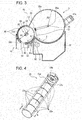
- Fig. 4 is a perspective view of the shutter 33.
- Fig. 5 is a cross-sectional view of a pertinent portion of the shutter 33 shown in Fig. 4 .
- the shutter 33 has a generally cylindrical shape, and has an outer diameter slightly smaller than the inner diameter of the sub chamber 38, so that the shutter 33 is rotatable in the sub chamber 38.
- the shutter 33 is formed of ABS resin.
- the shutter 33 includes six arcuate or circumferential ribs 33a, opening 33b, a closing wall 33c, an opening 33e, a closing wall 33d, and the sealing member 41.
- the circumferential ribs 33a are in the shape of an arc, which defines a part of the outer and inner diameters of the shutter 33.
- the circumferential ribs 33a are aligned at predetermined intervals H in a direction parallel to the rotational axis X1 ( Fig. 5 ) of the shutter 33, thereby defining openings 33e between adjacent circumferential ribs 33a.
- the openings 33e have a dimension H in the longitudinal direction of the shutter 33.
- Each circumferential rib has a width of t . In the present embodiment, the dimension H is 30 mm and the width of t is 4 mm.
- the number of circumferential ribs 33a may be selected according to the number of the sub films of a sub agitating film 35 of the sub agitator 30, for example, in the range of 1 to 5 or more than 7.
- the circumferential ribs 33a prevent the sub agitating film 35 from entering the main chamber 39 and a main agitating film 37 from entering the sub chamber 38.
- the circumferential ribs 33a prevent the sub agitator 30 and a second agitating member 49 ( Fig. 8 ) from interfering with each other even when the communication port 42 is open.
- the opening 33b ( Fig. 4 ) has substantially the same size and shape as the opening 40 formed in the sub chamber 38, and is positioned at substantially longitudinally mid portion of the developer material holding apparatus 5.
- the opening 33b becomes aligned with the opening 40 so that the sub chamber 38 communicates with the print engine 10 through the openings 33b and 40 and the developer material 4 is supplied into the print engine 10.
- the sealing member 41 provides a sealing environment for the opening 40.
- the sealing member 41 is located on the outer surface of the shutter 33, and is in the shape of a rectangular ring that surrounds the substantially rectangular opening 40. When the developer holding apparatus 5 has been attached to the print engine 10, the opening 40 faces the print engine 10 substantially downward.
- the relative positions among the opening 40, the communication port 42, the opening 33e, and the closing wall 33c of the shutter 33 are related as follows: When the shutter 33 is rotated so that the opening 33e becomes aligned with the communication port 42 (opening position), the opening 33e becomes aligned with the communication port 42. When the shutter 33 is rotated to bring the closing wall 33c into alignment with the communication port 42 (closing position), the closing wall 33d becomes aligned with the opening 40.
- the sub agitator 30 rotates in the sub chamber 38, while agitating the developer material 4 in the sub chamber 38.
- the sub agitator 30 includes a bar structure 34 and the sub agitating film 35. When the sub agitator 30 rotates, the sub agitating film 35 extending radially from the bar structure 34 scrapes the inner circumferential surface of the sub chamber 38.
- the bar structure 34 includes rotational shafts 34a that project from a body of the bar structure 34.
- the rotational shafts 34a extend oppositely substantially in the longitudinal direction of the bar structure 34, and are rotatably received in bearings (not shown) mounted at the longitudinal end walls of the sub chamber 38, so that the sub agitator 30 rotates in the sub chamber 38,
- the rotational axis X2 ( Fig. 6 ) of the rotational shafts 34a is substantially in line with the centerline of the inner cylindrical space in the sub chamber 38.
- the bar structure 34 includes a first mounting surface 34b and two inclined second mounting surfaces 34c.
- the bar structure 34 is in a single piece construction.
- the first mounting surface 34b is laterally centered between two longitudinal ends of the bar structure 34.
- the two second mounting surfaces 34c are positioned with the first mounting surface 34b located between the two second mounting surfaces.
- the first mounting surface 34b is contiguous with the second mounting surfaces 34c.
- the mounting surface 34b extends in a direction substantially parallel to the rotational axes of the rotational shafts 34a.
- Each of the second mounting surfaces 34c extends in such a direction as to become further away from the longitudinal axes of the rotational shafts 34a nearer the longitudinal end of the rotational shaft 34a.
- the bar structure 34 also includes five ribs 34d between the rotational shafts 34a
- the sub agitating film 35 has cuts 35b1-35b4 to define five resilient thin sub films 35a1-35a5 that can resiliently deflect independently of one another, so that the sub films 35a1-35a5 resiliently scrape the inner surface of the shutter 33.
- the sub films 35a1-35a5 are mounted on the mounting surfaces 34b and 34c of the bar structure 34, and extend from the first mounting surface 34b and second mounting surface 34c. When the bar structure 34 rotates, the free ends Y1-Y5 of the sub films 35a1-35a5 scrape the inner surface of the circumferential ribs 33a but do not interfere with the main agitating film 37 in the main chamber 39.
- the free end of the sub film 35a3 is further away from the longitudinal axes of the rotational shafts 34a than the free ends Y4 and Y2 of sub film 35a4 and 35a2.
- the free ends of the sub films 35a4, 35a5, 35a2, and 35a1 are further away from the rotational axis of the rotational shafts 34a nearer the longitudinal free ends of the bar structure 34.
- the sub agitating film 35 extends from the bar structure 34 in a direction substantially perpendicular to the rotational axes of the shafts 34a, and is in resilient contact with the inner surface of the shutter 33, thereby ensuring that the developer material 4 in the sub chamber 38 is supplied into the print engine 10.
- the sub films 35a1 and 35a5 located near the longitudinal ends of the sub agitator 30 contact the inner surface of the sub chamber 38 under higher pressure than the sub films 35a2 and 35a4 located between the sub films 35a1 and 35a5, so that the developer material 4 adhering to the inner surface of the sub chamber 38 is collected toward a longitudinally middle portion of the sub chamber 38.
- the free end of the sub film 35a3 is further away from the rotational axes of the shafts 34a than the portion of the sub films 35a1 and 35a5 immediately adjacent to the thin sub film 35a3, and strongly scrapes the inner surface of the shutter 33, thereby guiding the developer material 4 toward the opening 40. In this manner, the developer material 4 may be discharged into the print engine 10 through the opening 40.
- the distance R1 ( Fig. 3 ) between the rotational axis of the shafts 34a and the inner surface of the sub chamber 38 is 26 mm.
- the distance L1 between the free ends of the sub films 35a1 and 35a5 and the rotational axis of the rotational shafts 34a is 30 mm. Since the distances R1 and L1 are related such that R1 ⁇ L1, the sub agitating film 35 is in resilient contact with the inner circumferential surface of the shutter 33.
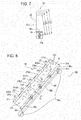
- Fig. 7 is a side view of the sub agitator 30.
- the sub agitating film 35 has a substantially L-shaped cross section with a long side 35m and a short side 35s.
- the short side 35s is fixed to the mounting surfaces 34b and 34c by, for example, thermal caulking.
- the five sub films 35a1-35a5 have lengths D1 D2, D3, D4, and D5 ( Fig. 6 ) in the longitudinal direction of the first agitating bar, respectively.
- the sub films 35a1, 35a2, and 35a3 have distances L1, L2, L3, and L4 from the rotational axis of the rotational shaft 34a, respectively.
- the L1 is the distance of the free end Y1 of the sub film 35a1 from the rotational axis of the rotational shaft 34a, the free end Y1 being at the longitudinal end of the sub agitating film 35.
- the L2 is the distance of the free end Y1 of the sub film 35a1, immediately adjacent the sub film 35a2, from the rotational axis of the rotational shaft 34a.
- the L3 is the distance of the free end Y2 of the sub film 35a2 from the rotational axis of the rotational shaft 34a, the free end Y2 being immediately adjacent the sub film 35a3.
- the L4 is the distance of the free end Y3 of the sub film 35a3 from the rotational axis of the rotational shaft 34a.
- the distances L1-L4 and R1 are related such that R1 ⁇ L3 ⁇ L1 ⁇ L4, and allow the sub agitating film 35 to be in resilient contact with the inner circumferential surface of the shutter 33, thereby ensuring that the developer material 4 is efficiently supplied into the engine 10 through the opening 40.
- the sub films 35a4 and 35a5 and the sub films 35a1 and 35a2 are symmetrical with respect to the sub film 35a3, and therefore the description of the distances of the thin sub films 35a4 and 35a5 from the rotational axes of the shafts 34a is omitted.
- the dimensions D1-D5 and the distances L1-L4 are related such that D1, D2, and D3 are 40 mm, D4 is 50 mm, D5 is 36 mm, L1 is 30 mm, L2 is 28 mm, L3 is 26 mm, and L4 is 35 mm.
- the sub agitating film 35 is formed of polyethylene terephthalate (PET), and has a thickness of 0.1 mm.
- PET polyethylene terephthalate
- the sub agitating film 35 may be formed of a variety of materials and have a variety of dimensions.
- the sub agitating film 35 may have more than five sub films.
- the bar structure 34 may be formed of other material than ABS resin.
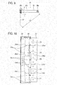
- Fig. 8 is a perspective view of the main agitator 49 and Fig. 9 is a cross-sectional view taken along a line C-C in Fig. 8 .
- the main agitator 49 includes a bar structure 36 formed in a one piece construction and a resilient thin film 37 mounted thereto.
- the bar structure 36 includes a mounting bar 36d, rotational shafts 36a, and supporting bars 36e.
- the rotational shafts 36a oppositely extend in a longitudinal direction of the bar structure 36.
- the supporting bars 36e extend in a radial direction from the mounting bar 36d.
- the resilient thin film 37 is mounted securely to the mounting bard 36d at a portion depicted at "A,” and extends in a direction perpendicular to the supporting bars 36e.
- the rotational shafts 36a are in line with a centerline of the cylindrical space of the main chamber 39.
- the shafts 36a are rotatably received in bearings at longitudinal ends of the main chamber 39, and the main agitator 49 rotates in a direction shown by arrow Z ( Fig. 3 ).
- the mounting bar 36d spans across the supporting bars 36e, thereby defining a space 36b bounded by the supporting bars 36e, bar 36f, and the mounting bar 36d.
- the resilient thin film 37 is fixed at its one end to the mounting bar 36d, and extends to the inner circumferential surface of the main chamber 39.
- the mounting bar 36d includes a tapered end 36c formed on a leading end thereof, tapered with respect to rotation of the main agitator 49, the tapered end being formed along the full length of the mounting bar 36d.
- the resilient thin film 37 may be unable to efficiently agitate the developer material 4 but the tapered end 36c of the mounting bar 36d is able to push its way through the pile of developer material while allowing the developer material 4 escaping through the space 36b. In this manner, the tapered end 36c prevents overloading of the resilient thin film 37.
- the resilient thin film 37 rotates so that the portion of the resilient thin film 37 fixed to the mounting bar 36d is a leading end and the free end of the resilient thin film 37 is a trailing end with respect to the direction of rotation of the main agitator 49.
- the resilient thin film 37 trails upstream of the direction of rotation of the main agitator 49.
- the free end resiliently drags the developer material 4 on the inner circumferential surface of the main chamber 39, thereby collecting the developer material 4.
- the resilient thin film includes five sub films 37a1-37a5 configured to resiliently deform independently of one another.
- This configuration minimizes the load exerted on the resilient thin film 37 during the rotation of the main agitator 49.
- the distance L5 between the rotational axis of the shafts 36a and the free end of the resilient thin film 37 is 56 mm. Selecting the distances R2 and L5 such that R2 ⁇ L5 causes the free ends Z1-Z5 of the resilient thin film 37 to resiliently contact the inner circumferential surface of the main chamber 39.
- the waste developer material chamber 32 may be separated from the developer material holding chamber 43, and includes a developer receiving opening 50 and a spiral 31.
- the developer receiving opening 50 receives the waste developer material, which failed to be transferred onto the paper 13.
- the waste developer material is directed through the developer receiving opening 50 into the back end of the waste developer material chamber 32 for efficient utilization of storing space.
- the main agitating film 37 has cuts 37b1-37b4 to define five resilient thin sub films 37a1-37a5 that can resiliently deflect independently of one another, so that the sub films 35a1-35a5 resiliently scrape the inner circumferential surface of the shutter 33.
- Each of the sub films 37a1-37a5 have holes 37c formed therein which alleviate the load on the sub films 37a1-37a5 exerted by the developer material 4.
- the sub films 37a1-37a5 have lengths D1, D2, D3, D4, and D5 extending in a direction parallel to the rotational axis of the shafts 36a, respectively, and a distance L5 ( Fig.
- the resilient thin film 37 has a thickness of 0.1 mm, and is formed of polyethylene terephthalate (PET).
- PET polyethylene terephthalate
- the bar structure 36 is formed of ABS resin. However, the resilient thin film 37 and the bar structure 36 may be formed of a variety of materials.
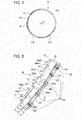
- Fig. 10 illustrates the positional relation among the circumferential ribs 33a, and the cuts 35b1-35b4 between the adjacent sub films 35a1-35a5 and the cuts 37b1-37b4 between the adjacent sub films 37a1-37a5.
- the circumferential ribs 33a do not face the cuts 35b1-35b4 and 37b1-37b4, or the cuts 35b1-35b4 and 37b1-37b4 do not face the circumferential rib 33a so that the circumferential ribs 33a do not enter the cuts 35b1-35b4. Therefore, the circumferential ribs 33a prevent the sub films 37a1-37a5 from entering the sub chamber 38 and the sub films 35a1-35a5 from entering the main chamber 39.
- the bar structure 36 formed of ABS resin is more rigid than the main agitating film 37 formed of PET.
- the supporting bars 36e extend from the bar 36f in directions perpendicular to the direction in which the rotational shafts 36a and the bar 36f extend.
- the main agitating film 37 is supported on a side of the supporting bars 36e opposite the bar 36f, and lies in a plane that forms an angle in the range of 60-150 degrees with the supporting bars 36e, preferably perpendicular to the bar 36f.
- the main agitating film 37 is away from the bar 36f and rotational shafts 36a, and lies in a plane parallel to the rotational shaft 36a and the bar 36f.
- Rollers 17-19 cooperate to receive the paper 13 from the paper cassette 16 and feed the paper 13 into the transport path 28.
- the transfer roller 12 transfers the developer image onto the paper 13.
- the fixing unit 22 fixes the developer image on the paper 13. After fixing, the paper 13 is discharged onto the stacker 27.
- the image forming unit 21 will be described.
- the charging roller 2 uniformly charges the surface of the photoconductive drum 1.
- the LED head 3 illuminates the charged surface of the photoconductive drum 1 to form an electrostatic latent image on the surface.
- the developer holding apparatus 5 is on the print engine 10, and supplies the developer material 4 into the print engine 10.
- the supplying roller 8 supplies the developer material 4 to the developing roller 6.
- the developing blade 7 forms a thin layer of the developer material 4.
- the thin layer is then brought into contact with the electrostatic latent image, thereby developing the electrostatic latent image intro a developer image 14.
- the developer image is then transferred by the transfer roller 12 onto the paper 13.
- the residual developer, which failed to be transferred onto the paper 13, is collected by the cleaning blade 9, and is transported by the spiral 15 to the side frame (not shown) of the print engine 10.
- the residual developer is further transported from the side frame to the developer receiving opening 50 through which the residual developer is stored into the waste developer material chamber 32.
- the residual developer in the waste developer material chamber 32 is spread by the spiral 31 so that the residual developer is efficiently stored in the
- Fig. 11 illustrates the developer holding apparatus 5 before it is unsealed, i.e., immediately after shipment from the factory.
- the opening 40 remains closed by the sealing wall 33d and sealing member 41 so that the developer material 4 will not leak from the developer holding apparatus 5.
- the communication port 42 is closed by the closing walls 33c. Therefore, even if unwanted physical forces are exerted on the developer holding apparatus 5 due to vibration during transportation and inadvertent dropping, the pressure of the developer material 4 in the main chamber 39 is not transmitted to the developer material in the sub chamber 38.
- the shutter 33 serves as a buffer mechanism, preventing the pressure of the developer material 4 in the main chamber 39 from being transmitted to the developer material in the sub chamber 38. This configuration prevents the developer material in the sub chamber 38 from leaking from the sub chamber 38 through the opening 40.
- the sub chamber 38 holds a smaller amount of developer material than the main chamber 39. Therefore, when the unwanted physical forces are exerted on the developer holding apparatus 5 due to vibration during transportation or inadvertent dropping, only the pressure of the developer material in the sub chamber 38 is exerted on the closing wall 33d that closes the opening 40. Therefore, the pressure exerted on the closing wall 33d can be minimized.
- Figs. 12-14 illustrate the position of the main agitator 49 as the main agitator 49 rotates in the Z direction.
- the operation of the developer holding apparatus 5 will be described with reference to Figs. 12-14 .
- the user operates a lever (not shown) to open the shutter 33.
- the opening 40 is opened and the developer material 4 may be supplied from the developer holding apparatus 5 into the print engine 10.
- the openings 33e are also in alignment with the communication port 42 so that the developer material 4 may be supplied from the main chamber 39 into the sub chamber 38.
- the main agitator 49 rotates so that the sub films 37a1-37a5 transport the developer material 4 from the main chamber 39 into the sub chamber 38.
- the sub agitator 30 also rotates so that the sub films 35a1-35a5 transport the developer material 4 from the sub chamber 38 into the print engine 10.
- the circumferential ribs 33a prevent the sub films 37a1-37a5 from entering the sub chamber 38 and the sub films 35a1-35a5 from entering the main chamber 39, the sub films 37a1-37a5 rubbing the outer arcuate surface of the circumferential ribs 33a and the sub films 35a1-35a5 rubbing the inner arcuate surface of the circumferential ribs 33a.
- the sub films 35a1-35a5 of the sub agitator 30 and the sub films 37a1-37a5 of the main agitator 49 rotate simultaneously to efficiently transport the developer material 4 into the print engine 10.
- the closing wall 33c of the shutter 33 prevents the pressure of the developer material 4 in the main chamber 39 from being exerted on the developer material 4 in the sub chamber 38, thereby minimizing the chance of the developer material 4 leaking from the sub chamber 38 through the opening 40. This configuration increases the reliability of the developer holding apparatus 5.
- the circumferential ribs 33a serve to isolate the sub films 37a1-7a5 from the sub films 35a1-35a5, and prevent the sub films 37a1-7a5 and the sub films 35a1-35a5 from interfering with each other. This prevents abnormal sounds or the increase in load on the sub films 37a1-7a5 and 35a1-35a5 which would otherwise be caused by the sub agitating film 35 and main agitating film 45 interfering with each other.
- One way of preventing the sub films 35a1-35a5 from interfering with the sub films 37a2-37a5 is to cause the sub agitator 30 and the main agitator 49 to rotate in such a way that the sub films 35a1-35a5 and 37a1-37a5 do not meet at the communication port 42 when they are rotating.
- such a configuration may lead to complicated design and assembly of the developer holding apparatus 5.
- Employing the circumferential ribs 33a simplifies the structure of the developer holding apparatus 5 and eliminates the complicated configuration of the sub films 35a1-35a5 and 37a1-37a5 such that they do not meet at the communication portion 42 when they are rotating.
- the sub films 37a1-37a5 should be highly resilient so that the sub films 37a1-37a5 repel the developer material 4 sufficiently and restore their original shape. However, when the sub films 37a1-37a5 repel the developer material 4, they may make abnormal sounds.
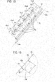
- Fig. 15 is a perspective view of a main agitator 49 according to a second embodiment.
- the dimensions D1-D5 are related such that D1, D2, and D3 are 40 mm, D4 is 50 mm, D5 is 36 mm.
- the sub agitating film 35 is formed of polyethylene terephthalate (PET), and has a thickness of 0.1 mm. However, the sub agitating film 35 may be formed of a variety of materials and have a variety of dimensions. In addition, the sub agitating film 35 may have more than five sub films.
- the bar structure 34 may be formed of other material than ABS resin.
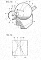
- Fig. 16 is an expanded view of a pertinent portion of the main agitating film 45.
- the bar structure 36 and main agitating film 45 according to the second embodiment will be described with reference to Fig. 15 and 16 .
- Elements similar to those of the first embodiment have been given the same reference numerals as the first embodiment, and their description is omitted.
- the main agitating film 45 has substantially the same shape as the main agitating film 37 except that each of sub films 45a1-45a5 of the main agitating film 45 has a corresponding pair of cuts or slits 45c as shown in Fig. 16 that define a deformable strip 45a therebetween.
- the cuts 45c have a length k of 2 mm, and are spaced apart by a distance P1 of 6 mm.
- Fig. 17 illustrates the positional relation between the circumferential ribs 33a of the shutter 33 and the cuts 45c of the main agitating film 45.
- each deformable strip 45a faces a corresponding one of the circumferential ribs 33a.
- the main agitating film 45 rotates so that the deformable strip 45a between a pair of cuts 45c is brought into pressure contact with a corresponding one of the circumferential ribs 33a.
- the free ends of the main agitating film 45 except for the deformable strip 45a extend toward the sub chamber 38 but not further than the inner surfaces of the circumferential ribs 33a ( Fig. 19 ), so that the sub agitating film 35 and main agitating film 45 do not interfere with each other.
- the developer holding apparatus 5 shipped from the factory holds a large amount of the developer material 4 as shown in Fig. 11 .
- Fig. 18 illustrates the operation of the developer holding apparatus 5 according to the second embodiment.
- Fig. 19 is an expanded view of a portion depicted at "d" in Fig. 18 .
- the pertinent portion of the operation of the developer holding apparatus 5 will be described with reference to Figs. 18 and 19 .
- Fig. 18 when the main agitator 49 rotates, the developer material 4 is conveyed through the opening 33e of the shutter 33 from the main chamber 39 into the sub chamber 38.
- the circumferential ribs 33a at the opening 33e in the shutter 33 prevent the sub agitating film 35 from entering the main chamber 39.
- Fig. 18 when the main agitator 49 rotates, the developer material 4 is conveyed through the opening 33e of the shutter 33 from the main chamber 39 into the sub chamber 38.
- the circumferential ribs 33a at the opening 33e in the shutter 33 prevent the sub agitating film 35 from entering the main chamber 39.
- the deformable strip 45a of the main agitating film 45 abuts the corresponding one of the circumferential ribs 33a, so that the deformable strip 45a deflects away from the circumferential rib 33a, and a base portion 45b of the deformable strip 45a between the cuts 45c abuts the outer arcuate surface G of the circumferential ribs 33a.
- edge portions of the main agitating film 45 except the deformable strips 45a extend into the openings 33e further than the outer arcuate surface of the circumferential ribs 33a and serves to push the developer material 4 in the sub chamber 38 toward the opening 40. This increases the ability of the main agitating film 45 to deliver the developer material 4 into the sub chamber 38.
- the sub and main agitators 30 and 49 rotate further from a position as shown Fig. 13 , reaching a position as shown in Fig. 14 where the developer material 4 is pushed by the sub agitating film 35 toward the opening 40.
- the second embodiment provides the following effects in addition to those of the first embodiment.
- the free end portions of the main agitating film 45 except for the deformable strips 45a extend into the openings 33e but not further than the inner circumferential surface of the circumferential ribs 33a. This configuration is effective in minimizing the chance of the developer material 4 being left unused in the main chamber 39.
- the free end portions except for the deformable strips 45a extend into the openings 33 but do not interfere with the sub agitating film 35, thereby eliminating abnormal sounds or the increase in load on the sub films 37a1-7a5 and 35a1-35a5, which would otherwise be caused by the sub agitating film 35 and main agitating film 45 interfering with each other.
- FIGs. 20 and 21 illustrate a first modification to the second embodiment.
- a main agitating film 46 according to the first modification has substantially the same shape as the main agitating film 45 according to the second embodiment.
- the main agitating film 46 has L-shaped cuts 46b that define a deformable strip 46a.
- the L-shaped cuts 46b include a short side 46b1 and a long side 46b2.
- the short side 46b1 extends in a direction substantially perpendicular to a direction in which rotational shafts 36a extend.
- the long side 46b2 extends in a direction substantially parallel to the direction in which the rotational shafts 36a extend.
- the short side 46b1 has a length k, e.g., 2 mm.
- the long side 46b2 has a length P, e.g. 6 mm.
- the deformable strip 46a abuts the outer arcuate surface of the circumferential rib 33a, and provides similar effects to the main agitating film 45 of those of the second embodiment.
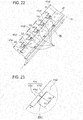
- FIGs. 22 and 23 illustrate a second modification to the second embodiment.
- a main agitating film 47 according to the second modification has substantially the same shape as the main agitating film 45 according to the second embodiment.
- the main agitating film 47 has T-shaped cuts 47b.
- Each T-shaped cut 47b includes a base leg 47b1 and an upstanding leg 47b2 disposed centrally normally to the base leg 47b1.
- the base leg 47b1 extends in a direction substantially parallel to a direction in which the shafts 36a extend, and the upstanding leg 47b2 extends in a direction substantially perpendicular to a direction in which the shafts 36a extend, thereby defining two deformable strips 47a1 and 47a2.
- the upstanding leg 47b2 has a length k of 2 mm, and extends from a longitudinally middle point of the long side.
- the base leg 47b1 has a length 2 ⁇ P2, e.g., 2 ⁇ 3 mm.
- the deformable strips 47a1 and 47a2 abut the outer arcuate surface of the circumferential rib 33a, providing effects similar to those obtained from the main agitating film 45 of the second embodiment.
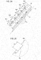
- Figs. 24 and 25 illustrate a third modification to the second embodiment.
- the third modification differs from the second embodiment in that a main agitating film 48 has a plurality of cutouts 48a.
- the cutout 48a has a depth k, e.g., 2 mm and a width P3, e.g., 3 mm.
- the present invention has been described in terms of a developer material holding apparatus for use in a printer. However, the invention may also be applied to conventional image forming units and image forming apparatus including a facsimile machine, a copying machine, and a multifunction peripheral that is equipped with a developer material holding device and an image forming unit.
Landscapes
- Physics & Mathematics (AREA)
- General Physics & Mathematics (AREA)
- Dry Development In Electrophotography (AREA)
Abstract
Description
- The present invention relates to a developer holding apparatus that holds a developer material therein, an image forming unit that uses the developer holding apparatus, and an image forming apparatus that uses the developer holding apparatus.
- Developer holding apparatus that hold a developer material therein are well known. A developer holding apparatus is shipped from the factory with a developer material loaded therein, and is attached to an image forming unit or an image forming apparatus when in use. The developer holding apparatus supplies the developer material for forming an image.
- Japanese Patent Laid-Open No.
2011-118040 - Even when a developer holding device is designed to have a large capacity, the device is required to have improved reliability.
- An object of the invention is to provide a developer holding apparatus capable of efficiently supplying a developer material to an image forming unit or an image forming apparatus.
- A developer holding apparatus includes a first chamber (38), a second chamber (39), a communication port (42), and a shutter (33). The first chamber (38) holds a developer material therein. The second chamber (39) is adjacent the first chamber (38), and holds the developer material therein. The first chamber communicates with the second chamber (39) through the communication port (42). The shutter (33) opens and closes the communication port (42).
- Further scope of applicability of the present invention will become apparent from the detailed description given hereinafter. However, it should be understood that the detailed description and specific examples, while indicating preferred embodiments of the invention, are given by way of illustration only, since various changes and modifications within the spirit and scope of the invention will become apparent to those skilled in the art from this detailed description.
- The present invention will become more fully understood from the detailed description given hereinbelow and the accompanying drawings which are given by way of illustration only, and thus are not limiting the present invention, and wherein:
-
Fig. 1 illustrates the outline of an image forming apparatus according to the present inventionFig. 2 illustrates the outline of an image forming unit; -
Fig. 3 is a cross-sectional view of the developer holding device according to the first embodiment; -
Fig. 4 is a perspective view of a shutter; -
Fig. 5 is a cross-sectional view of the shutter taken along a line A-A inFig. 4 ; -
Fig. 6 is a perspective view illustrating the sub agitator; -
Fig. 7 is a side view of the sub agitator; -
Fig. 8 is a perspective view of the main agitator; -
Fig. 9 is a cross-sectional view taken along a line C-C inFig. 8 ; -
Fig. 10 illustrates the positional relation among arcuate ribs and the boundaries between adjacent sub films. -
Fig. 11 illustrates the developer holding device before it is unsealed; -
Figs. 12-14 illustrate the position of the main agitator as the main agitator rotates in the Z direction; -
Fig. 15 is a perspective view of a main agitator according to a second embodiment; -
Fig. 16 is an expanded view of a pertinent portion of a main agitating film; -
Fig. 17 illustrates the positional relation between the arcuate ribs of theshutter 33 and the cuts of the main agitating film; -
Fig. 18 illustrates the operation of a developer holding device according to the second embodiment; -
Fig. 19 is an expanded view of a portion depicted at "d" inFig. 18 ; -
Figs. 20 and 21 illustrate a first modification to the second embodiment; -
Figs. 22 and 23 illustrate a second modification to the second embodiment; and -
Figs. 24 and 25 illustrate a third modification to the second embodiment. - Embodiments of the invention will be described with reference to the accompanying drawings. The invention is not limited to these embodiments. A developer holding apparatus according to the present invention is used with an image forming unit or an image forming apparatus which may take a variety of forms. For simplicity, the invention will be described with respect to an image forming apparatus.
-
Fig. 1 illustrates an outline of animage forming apparatus 29 according to a first embodiment of the present invention. - The
image forming apparatus 29 includes apaper transporting path 28 that includes paper transporting rollers 17-19 and discharging rollers 23-26. Apaper cassette 16 is disposed upstream of thepaper transport path 28, and holds a stack ofpaper 13 as a recording medium. Astacker 27 is located downstream of thepaper transporting path 28, and temporarily holds printed paper. Thepaper transporting path 28 also includes atransfer roller 12 that transfers a developer image onto thepaper 13 and afixing unit 22 that fuses the developer image into thepaper 13. Thetransfer roller 12 is disposed immediately under animage forming unit 21. -
Fig. 2 illustrates the outline of theimage forming unit 21. Theimage forming unit 21 includes adeveloper holding apparatus 5, disposed at an upper portion of theimage forming unit 21, and aprint engine 10 disposed under thedeveloper holding apparatus 5. Theprint engine 10 includes a photoconductive drum 1, acharging roller 2, a light emitting diode (LED)head 3, and a developingroller 6, acleaning blade 9, atransport spiral 15, and awaste toner holder 20. The photoconductive drum 1 is rotatably supported so that the photoconductive drum 1 is driven in rotation by a drive source (not shown). The photoconductive drum 1 is capable of storing charges on its surface. TheLED head 3 illuminates the charged surface of the photoconductive drum 1 in accordance with print data, thereby creating an electrostatic latent image on the photoconductive drum 1. - The
charging roller 2 is in pressure contact with the surface of the photoconductive drum 1, and supplies a predetermined amount of charge to the surface of the photoconductive drum 1. Thecharging roller 2 rotates in the same direction as the photoconductive drum 1. TheLED head 3 is disposed over the photoconductive drum 1, and illuminates the charged surface of the photoconductive drum 1 to dissipate the charge on the photoconductive drum 1, thereby forming an electrostatic latent image on the photoconductive drum 1. Thedeveloper holding apparatus 5 is located above theprint engine 10, holds a developer material (e.g., toner) 4 therein, and supplies thedeveloper material 4 to theprint engine 10. - A developing
roller 6 receives thedeveloper material 4 from thedeveloper holding apparatus 5, and supplies thedeveloper material 4 to the electrostatic latent image formed on the photoconductive drum 1. A developermaterial supplying roller 8 supplies thedeveloper material 4 to the developingroller 6. The developing blade 7 is in pressure contact with the developingroller 6, and forms a layer of thedeveloper material 4 having a predetermined thickness on the developingroller 6. - The
print engine 10 includes anopening 51 through which thedeveloper material 4 is received from thedeveloper holding apparatus 5. Once thedeveloper holding apparatus 5 is attached to theprint engine 10, the opening 51 (Fig. 3 ) is in alignment with a rectangular opening 40 (Fig. 3 ) formed in thedeveloper holding apparatus 5. - The
transfer roller 12 is disposed immediately under the photoconductive drum 1. Thecleaning blade 9 is located immediately downstream of thetransfer roller 12 with respect to rotation of the photoconductive drum 1. Thecleaning blade 9 is in pressure contact with the surface of the photoconductive drum 1, and scrapes the residual developer material adhering to the surface of the photoconductive drum 1 after transfer of the developer image onto the paper, thereby collecting the waste developer material into thewaste developer holder 20. Thespiral 15 is located in the vicinity of thecleaning blade 9, and transports the scraped residual developer material into a side frame (not shown). -
Fig. 3 is a cross-sectional view of thedeveloper holding apparatus 5 according to the first embodiment. Thedeveloper holding apparatus 5 will be described with reference toFig. 3 . Thedeveloper holding apparatus 5 is attached to theprint engine 10, and supplies thedeveloper material 4 into theprint engine 10. Thedeveloper holding apparatus 5 includes adeveloper material chamber 43 that holds thedeveloper material 4 therein, a wastedeveloper material chamber 32 that holds the residual developer material that failed to be transferred onto thepaper 13, and ahandle 43a that is gripped by the user when the user attaches thedeveloper holding apparatus 5 onto theprint engine 10. - The
developer material chamber 43 includes asub chamber 38 in the shape of a small-diameter hollow cylinder that holds a small amount of thedeveloper material 4 therein, amain chamber 39 in the shape of a large-diameter hollow cylinder that holds a large amount of thedeveloper material 4 therein, and acommunication port 42 through which the first andsecond chambers sub chamber 38 has a shape such that a small-diameter hollow cylinder is cut in a plane parallel to the longitudinal axis of the small-diameter hollow cylinder. Themain chamber 39 has a shape such that a large-diameter hollow cylinder is cut in a plane parallel to the longitudinal axis of the large-diameter hollow cylinder. The first andsecond chambers developer material 4 is directed from themain chamber 39 into thesub chamber 38 through thecommunication port 42, and then into theprint engine 10 via theopening 33b formed in the shutter 33 (Fig. 4 ), theopening 40 formed in thesub chamber 38, and theopening 51 formed in theprint engine 10. - Once the
developer holding apparatus 5 is attached to theprint engine 10, thedeveloper material chamber 43 is oriented such that the main andsub chambers developer holding apparatus 5 is maintained at a minimum height in theimage forming apparatus 29. - The
sub chamber 38 includes ashutter 33, asub agitator 30, and theopening 40. - The
shutter 33 is rotatably received in thesub chamber 38, and simultaneously opens and closes theopening 40 and thecommunication port 42. In other words, theshutter 33 rotates in thesub chamber 38 to open and close theopening 40. Theshutter 33 also rotates in thesub chamber 38 to open and close thecommunication port 42 through which the sub andmain chambers developer holding apparatus 5 has been attached to theprint engine 10, the user operates a lever (not shown) to rotate theshutter 33 between an opening position and a closing position. Theshutter 33 closes both theopening 40 and thecommunication port 42 simultaneously, so that thedeveloper material 4 is prevented from leaking from thedeveloper holding apparatus 5 when thedeveloper holding apparatus 5 is subjected to impact due to, for example, dropping. A sealingmember 41 and a sealingwall 33d cooperate with each other to close theopening 40 hermetically, thereby preventing thedeveloper material 4 in thesub chamber 38 from leaking through theopening 40. A sealingwall 33c closes thecommunication port 42, thereby preventing the pressure by thedeveloper material 4 in themain chamber 39 from being exerted on the developer material in thesub chamber 38. This configuration prevents the sealing effect at theopening 40 from deteriorating. In other words, theshutter 33 and thesub chamber 38 serves as a buffer mechanism between themain chamber 43 and theprint engine 10. -
Fig. 4 is a perspective view of theshutter 33.Fig. 5 is a cross-sectional view of a pertinent portion of theshutter 33 shown inFig. 4 . Theshutter 33 has a generally cylindrical shape, and has an outer diameter slightly smaller than the inner diameter of thesub chamber 38, so that theshutter 33 is rotatable in thesub chamber 38. Theshutter 33 is formed of ABS resin. - The
shutter 33 includes six arcuate orcircumferential ribs 33a, opening 33b, aclosing wall 33c, anopening 33e, aclosing wall 33d, and the sealingmember 41. - The
circumferential ribs 33a are in the shape of an arc, which defines a part of the outer and inner diameters of theshutter 33. Thecircumferential ribs 33a are aligned at predetermined intervals H in a direction parallel to the rotational axis X1 (Fig. 5 ) of theshutter 33, thereby definingopenings 33e between adjacentcircumferential ribs 33a. Theopenings 33e have a dimension H in the longitudinal direction of theshutter 33. Each circumferential rib has a width of t. In the present embodiment, the dimension H is 30 mm and the width of t is 4 mm. The number ofcircumferential ribs 33a, which will be described later, may be selected according to the number of the sub films of asub agitating film 35 of thesub agitator 30, for example, in the range of 1 to 5 or more than 7. When theshutter 33 opens thecommunication port 42, thecircumferential ribs 33a prevent thesub agitating film 35 from entering themain chamber 39 and a main agitatingfilm 37 from entering thesub chamber 38. In other words, thecircumferential ribs 33a prevent thesub agitator 30 and a second agitating member 49 (Fig. 8 ) from interfering with each other even when thecommunication port 42 is open. - The
opening 33b (Fig. 4 ) has substantially the same size and shape as theopening 40 formed in thesub chamber 38, and is positioned at substantially longitudinally mid portion of the developermaterial holding apparatus 5. When theshutter 33 is rotated in an opening direction, theopening 33b becomes aligned with theopening 40 so that thesub chamber 38 communicates with theprint engine 10 through theopenings developer material 4 is supplied into theprint engine 10. - When the
shutter 33 is rotated in a closing direction (opposite to a Q direction shown inFig. 3 ), the closingwall 33c becomes aligned with thecommunication port 42, closing thecommunication port 42. - When the
shutter 33 rotates in the closing direction, theclosing wall 33d is brought into alignment with theopening 40, closing theopening 40. - The sealing
member 41 provides a sealing environment for theopening 40. The sealingmember 41 is located on the outer surface of theshutter 33, and is in the shape of a rectangular ring that surrounds the substantiallyrectangular opening 40. When thedeveloper holding apparatus 5 has been attached to theprint engine 10, theopening 40 faces theprint engine 10 substantially downward. - The relative positions among the opening 40, the
communication port 42, theopening 33e, and theclosing wall 33c of theshutter 33 are related as follows: When theshutter 33 is rotated so that theopening 33e becomes aligned with the communication port 42 (opening position), theopening 33e becomes aligned with thecommunication port 42. When theshutter 33 is rotated to bring theclosing wall 33c into alignment with the communication port 42 (closing position), theclosing wall 33d becomes aligned with theopening 40. - The
sub agitator 30 rotates in thesub chamber 38, while agitating thedeveloper material 4 in thesub chamber 38. Thesub agitator 30 includes abar structure 34 and thesub agitating film 35. When thesub agitator 30 rotates, thesub agitating film 35 extending radially from thebar structure 34 scrapes the inner circumferential surface of thesub chamber 38. Thebar structure 34 includesrotational shafts 34a that project from a body of thebar structure 34. Therotational shafts 34a extend oppositely substantially in the longitudinal direction of thebar structure 34, and are rotatably received in bearings (not shown) mounted at the longitudinal end walls of thesub chamber 38, so that thesub agitator 30 rotates in thesub chamber 38, The rotational axis X2 (Fig. 6 ) of therotational shafts 34a is substantially in line with the centerline of the inner cylindrical space in thesub chamber 38. -
Fig. 6 illustrates thesub agitator 30. Thebar structure 34 includes a first mountingsurface 34b and two inclined second mountingsurfaces 34c. Thebar structure 34 is in a single piece construction. Thefirst mounting surface 34b is laterally centered between two longitudinal ends of thebar structure 34. The two second mounting surfaces 34c are positioned with the first mountingsurface 34b located between the two second mounting surfaces. Thefirst mounting surface 34b is contiguous with the second mounting surfaces 34c. The mountingsurface 34b extends in a direction substantially parallel to the rotational axes of therotational shafts 34a. Each of the second mountingsurfaces 34c extends in such a direction as to become further away from the longitudinal axes of therotational shafts 34a nearer the longitudinal end of therotational shaft 34a. Thebar structure 34 also includes fiveribs 34d between therotational shafts 34a - The
sub agitating film 35 has cuts 35b1-35b4 to define five resilient thin sub films 35a1-35a5 that can resiliently deflect independently of one another, so that the sub films 35a1-35a5 resiliently scrape the inner surface of theshutter 33. The sub films 35a1-35a5 are mounted on the mountingsurfaces bar structure 34, and extend from the first mountingsurface 34b and second mountingsurface 34c. When thebar structure 34 rotates, the free ends Y1-Y5 of the sub films 35a1-35a5 scrape the inner surface of thecircumferential ribs 33a but do not interfere with the main agitatingfilm 37 in themain chamber 39. - The free end of the sub film 35a3 is further away from the longitudinal axes of the
rotational shafts 34a than the free ends Y4 and Y2 of sub film 35a4 and 35a2. The free ends of the sub films 35a4, 35a5, 35a2, and 35a1 are further away from the rotational axis of therotational shafts 34a nearer the longitudinal free ends of thebar structure 34. - The
sub agitating film 35 extends from thebar structure 34 in a direction substantially perpendicular to the rotational axes of theshafts 34a, and is in resilient contact with the inner surface of theshutter 33, thereby ensuring that thedeveloper material 4 in thesub chamber 38 is supplied into theprint engine 10. In other words, the sub films 35a1 and 35a5 located near the longitudinal ends of thesub agitator 30 contact the inner surface of thesub chamber 38 under higher pressure than the sub films 35a2 and 35a4 located between the sub films 35a1 and 35a5, so that thedeveloper material 4 adhering to the inner surface of thesub chamber 38 is collected toward a longitudinally middle portion of thesub chamber 38. The free end of the sub film 35a3 is further away from the rotational axes of theshafts 34a than the portion of the sub films 35a1 and 35a5 immediately adjacent to the thin sub film 35a3, and strongly scrapes the inner surface of theshutter 33, thereby guiding thedeveloper material 4 toward theopening 40. In this manner, thedeveloper material 4 may be discharged into theprint engine 10 through theopening 40. - Specifically, the distance R1 (
Fig. 3 ) between the rotational axis of theshafts 34a and the inner surface of thesub chamber 38 is 26 mm. The distance L1 between the free ends of the sub films 35a1 and 35a5 and the rotational axis of therotational shafts 34a is 30 mm. Since the distances R1 and L1 are related such that R1<L1, thesub agitating film 35 is in resilient contact with the inner circumferential surface of theshutter 33. -
Fig. 7 is a side view of thesub agitator 30. - The
sub agitating film 35 has a substantially L-shaped cross section with along side 35m and ashort side 35s. Theshort side 35s is fixed to the mountingsurfaces - The five sub films 35a1-35a5 have lengths D1 D2, D3, D4, and D5 (
Fig. 6 ) in the longitudinal direction of the first agitating bar, respectively. - The sub films 35a1, 35a2, and 35a3 have distances L1, L2, L3, and L4 from the rotational axis of the
rotational shaft 34a, respectively. The L1 is the distance of the free end Y1 of the sub film 35a1 from the rotational axis of therotational shaft 34a, the free end Y1 being at the longitudinal end of thesub agitating film 35. The L2 is the distance of the free end Y1 of the sub film 35a1, immediately adjacent the sub film 35a2, from the rotational axis of therotational shaft 34a. The L3 is the distance of the free end Y2 of the sub film 35a2 from the rotational axis of therotational shaft 34a, the free end Y2 being immediately adjacent the sub film 35a3. The L4 is the distance of the free end Y3 of the sub film 35a3 from the rotational axis of therotational shaft 34a. The distances L1-L4 and R1 are related such that R1<L3<L1<L4, and allow thesub agitating film 35 to be in resilient contact with the inner circumferential surface of theshutter 33, thereby ensuring that thedeveloper material 4 is efficiently supplied into theengine 10 through theopening 40. - The sub films 35a4 and 35a5 and the sub films 35a1 and 35a2 are symmetrical with respect to the sub film 35a3, and therefore the description of the distances of the thin sub films 35a4 and 35a5 from the rotational axes of the
shafts 34a is omitted. - Referring to
Fig. 6 , the dimensions D1-D5 and the distances L1-L4 are related such that D1, D2, and D3 are 40 mm, D4 is 50 mm, D5 is 36 mm, L1 is 30 mm, L2 is 28 mm, L3 is 26 mm, and L4 is 35 mm. Thesub agitating film 35 is formed of polyethylene terephthalate (PET), and has a thickness of 0.1 mm. However, thesub agitating film 35 may be formed of a variety of materials and have a variety of dimensions. In addition, thesub agitating film 35 may have more than five sub films. Thebar structure 34 may be formed of other material than ABS resin. -
Fig. 8 is a perspective view of themain agitator 49 andFig. 9 is a cross-sectional view taken along a line C-C inFig. 8 . Themain agitator 49 includes abar structure 36 formed in a one piece construction and a resilientthin film 37 mounted thereto. Thebar structure 36 includes a mountingbar 36d,rotational shafts 36a, and supportingbars 36e. Therotational shafts 36a oppositely extend in a longitudinal direction of thebar structure 36. The supportingbars 36e extend in a radial direction from the mountingbar 36d. The resilientthin film 37 is mounted securely to the mountingbard 36d at a portion depicted at "A," and extends in a direction perpendicular to the supportingbars 36e. Therotational shafts 36a are in line with a centerline of the cylindrical space of themain chamber 39. Theshafts 36a are rotatably received in bearings at longitudinal ends of themain chamber 39, and themain agitator 49 rotates in a direction shown by arrow Z (Fig. 3 ). - The mounting
bar 36d spans across the supportingbars 36e, thereby defining aspace 36b bounded by the supportingbars 36e,bar 36f, and the mountingbar 36d. The resilientthin film 37 is fixed at its one end to the mountingbar 36d, and extends to the inner circumferential surface of themain chamber 39. The mountingbar 36d includes atapered end 36c formed on a leading end thereof, tapered with respect to rotation of themain agitator 49, the tapered end being formed along the full length of the mountingbar 36d. When themain chamber 39 holds a large amount of thedeveloper material 4 therein, the resilientthin film 37 may be unable to efficiently agitate thedeveloper material 4 but thetapered end 36c of the mountingbar 36d is able to push its way through the pile of developer material while allowing thedeveloper material 4 escaping through thespace 36b. In this manner, thetapered end 36c prevents overloading of the resilientthin film 37. - When the
main agitator 49 rotates in the Z direction, the resilientthin film 37 rotates so that the portion of the resilientthin film 37 fixed to the mountingbar 36d is a leading end and the free end of the resilientthin film 37 is a trailing end with respect to the direction of rotation of themain agitator 49. In other words, the resilientthin film 37 trails upstream of the direction of rotation of themain agitator 49. The free end resiliently drags thedeveloper material 4 on the inner circumferential surface of themain chamber 39, thereby collecting thedeveloper material 4. The resilient thin film includes five sub films 37a1-37a5 configured to resiliently deform independently of one another. Just as in the resilientthin film 35 of thesub agitator 30, when themain agitator 49 rotates, the free ends Z1-Z5 of the sub films 37a1-37a5 scrape the outer circumferential surface of thecircumferential ribs 33a but do not interfere with the sub films 35a1-35a5 in thesub chamber 38. - This configuration minimizes the load exerted on the resilient
thin film 37 during the rotation of themain agitator 49. The distance L5 between the rotational axis of theshafts 36a and the free end of the resilientthin film 37 is 56 mm. Selecting the distances R2 and L5 such that R2<L5 causes the free ends Z1-Z5 of the resilientthin film 37 to resiliently contact the inner circumferential surface of themain chamber 39. - The waste
developer material chamber 32 may be separated from the developermaterial holding chamber 43, and includes adeveloper receiving opening 50 and aspiral 31. Thedeveloper receiving opening 50 receives the waste developer material, which failed to be transferred onto thepaper 13. The waste developer material is directed through thedeveloper receiving opening 50 into the back end of the wastedeveloper material chamber 32 for efficient utilization of storing space. - The main agitating
film 37 has cuts 37b1-37b4 to define five resilient thin sub films 37a1-37a5 that can resiliently deflect independently of one another, so that the sub films 35a1-35a5 resiliently scrape the inner circumferential surface of theshutter 33. Each of the sub films 37a1-37a5 haveholes 37c formed therein which alleviate the load on the sub films 37a1-37a5 exerted by thedeveloper material 4. The sub films 37a1-37a5 have lengths D1, D2, D3, D4, and D5 extending in a direction parallel to the rotational axis of theshafts 36a, respectively, and a distance L5 (Fig. 9 ) between the free ends Z1-Z5 of sub films 37a1-37a5 and the rotational axis of theshafts 36a. The resilientthin film 37 has a thickness of 0.1 mm, and is formed of polyethylene terephthalate (PET). Thebar structure 36 is formed of ABS resin. However, the resilientthin film 37 and thebar structure 36 may be formed of a variety of materials. -
Fig. 10 illustrates the positional relation among thecircumferential ribs 33a, and the cuts 35b1-35b4 between the adjacent sub films 35a1-35a5 and the cuts 37b1-37b4 between the adjacent sub films 37a1-37a5. It is to be noted that thecircumferential ribs 33a do not face the cuts 35b1-35b4 and 37b1-37b4, or the cuts 35b1-35b4 and 37b1-37b4 do not face thecircumferential rib 33a so that thecircumferential ribs 33a do not enter the cuts 35b1-35b4. Therefore, thecircumferential ribs 33a prevent the sub films 37a1-37a5 from entering thesub chamber 38 and the sub films 35a1-35a5 from entering themain chamber 39. - The
bar structure 36 formed of ABS resin is more rigid than the main agitatingfilm 37 formed of PET. The supportingbars 36e extend from thebar 36f in directions perpendicular to the direction in which therotational shafts 36a and thebar 36f extend. The main agitatingfilm 37 is supported on a side of the supportingbars 36e opposite thebar 36f, and lies in a plane that forms an angle in the range of 60-150 degrees with the supportingbars 36e, preferably perpendicular to thebar 36f. In other words, the main agitatingfilm 37 is away from thebar 36f androtational shafts 36a, and lies in a plane parallel to therotational shaft 36a and thebar 36f. - Rollers 17-19 cooperate to receive the
paper 13 from thepaper cassette 16 and feed thepaper 13 into thetransport path 28. Thetransfer roller 12 transfers the developer image onto thepaper 13. The fixingunit 22 fixes the developer image on thepaper 13. After fixing, thepaper 13 is discharged onto thestacker 27. - The
image forming unit 21 will be described. - The charging
roller 2 uniformly charges the surface of the photoconductive drum 1. TheLED head 3 illuminates the charged surface of the photoconductive drum 1 to form an electrostatic latent image on the surface. Thedeveloper holding apparatus 5 is on theprint engine 10, and supplies thedeveloper material 4 into theprint engine 10. The supplyingroller 8 supplies thedeveloper material 4 to the developingroller 6. The developing blade 7 forms a thin layer of thedeveloper material 4. The thin layer is then brought into contact with the electrostatic latent image, thereby developing the electrostatic latent image intro adeveloper image 14. The developer image is then transferred by thetransfer roller 12 onto thepaper 13. The residual developer, which failed to be transferred onto thepaper 13, is collected by thecleaning blade 9, and is transported by the spiral 15 to the side frame (not shown) of theprint engine 10. The residual developer is further transported from the side frame to thedeveloper receiving opening 50 through which the residual developer is stored into the wastedeveloper material chamber 32. The residual developer in the wastedeveloper material chamber 32 is spread by the spiral 31 so that the residual developer is efficiently stored in the wastedeveloper material chamber 32. - The
developer holding apparatus 5 will be described with reference toFig. 11. Fig. 11 illustrates thedeveloper holding apparatus 5 before it is unsealed, i.e., immediately after shipment from the factory. When thedeveloper holding apparatus 5 remains unsealed, theopening 40 remains closed by the sealingwall 33d and sealingmember 41 so that thedeveloper material 4 will not leak from thedeveloper holding apparatus 5. Thecommunication port 42 is closed by the closingwalls 33c. Therefore, even if unwanted physical forces are exerted on thedeveloper holding apparatus 5 due to vibration during transportation and inadvertent dropping, the pressure of thedeveloper material 4 in themain chamber 39 is not transmitted to the developer material in thesub chamber 38. In other words, theshutter 33 serves as a buffer mechanism, preventing the pressure of thedeveloper material 4 in themain chamber 39 from being transmitted to the developer material in thesub chamber 38. This configuration prevents the developer material in thesub chamber 38 from leaking from thesub chamber 38 through theopening 40. - It is to be noted that the
sub chamber 38 holds a smaller amount of developer material than themain chamber 39. Therefore, when the unwanted physical forces are exerted on thedeveloper holding apparatus 5 due to vibration during transportation or inadvertent dropping, only the pressure of the developer material in thesub chamber 38 is exerted on theclosing wall 33d that closes theopening 40. Therefore, the pressure exerted on theclosing wall 33d can be minimized. -
Figs. 12-14 illustrate the position of themain agitator 49 as themain agitator 49 rotates in the Z direction. The operation of thedeveloper holding apparatus 5 will be described with reference toFigs. 12-14 . Assume that when themain agitator 49 is inFig. 12 position, the user operates a lever (not shown) to open theshutter 33. Theopening 40 is opened and thedeveloper material 4 may be supplied from thedeveloper holding apparatus 5 into theprint engine 10. When theopening 40 is opened, theopenings 33e are also in alignment with thecommunication port 42 so that thedeveloper material 4 may be supplied from themain chamber 39 into thesub chamber 38. - Referring to
Fig. 13 , themain agitator 49 rotates so that the sub films 37a1-37a5 transport thedeveloper material 4 from themain chamber 39 into thesub chamber 38. Thesub agitator 30 also rotates so that the sub films 35a1-35a5 transport thedeveloper material 4 from thesub chamber 38 into theprint engine 10. Thecircumferential ribs 33a prevent the sub films 37a1-37a5 from entering thesub chamber 38 and the sub films 35a1-35a5 from entering themain chamber 39, the sub films 37a1-37a5 rubbing the outer arcuate surface of thecircumferential ribs 33a and the sub films 35a1-35a5 rubbing the inner arcuate surface of thecircumferential ribs 33a. - The sub films 35a1-35a5 of the
sub agitator 30 and the sub films 37a1-37a5 of themain agitator 49 rotate simultaneously to efficiently transport thedeveloper material 4 into theprint engine 10. - Until the
developer holding apparatus 5 is attached to theprint engine 10, the closingwall 33c of theshutter 33 prevents the pressure of thedeveloper material 4 in themain chamber 39 from being exerted on thedeveloper material 4 in thesub chamber 38, thereby minimizing the chance of thedeveloper material 4 leaking from thesub chamber 38 through theopening 40. This configuration increases the reliability of thedeveloper holding apparatus 5. - The
circumferential ribs 33a serve to isolate the sub films 37a1-7a5 from the sub films 35a1-35a5, and prevent the sub films 37a1-7a5 and the sub films 35a1-35a5 from interfering with each other. This prevents abnormal sounds or the increase in load on the sub films 37a1-7a5 and 35a1-35a5 which would otherwise be caused by thesub agitating film 35 and main agitatingfilm 45 interfering with each other. - One way of preventing the sub films 35a1-35a5 from interfering with the sub films 37a2-37a5 is to cause the
sub agitator 30 and themain agitator 49 to rotate in such a way that the sub films 35a1-35a5 and 37a1-37a5 do not meet at thecommunication port 42 when they are rotating. However, such a configuration may lead to complicated design and assembly of thedeveloper holding apparatus 5. Employing thecircumferential ribs 33a simplifies the structure of thedeveloper holding apparatus 5 and eliminates the complicated configuration of the sub films 35a1-35a5 and 37a1-37a5 such that they do not meet at thecommunication portion 42 when they are rotating. - If the sub and
main agitators communication port 42 when they are rotating, the sub films 37a1-37a5 should be highly resilient so that the sub films 37a1-37a5 repel thedeveloper material 4 sufficiently and restore their original shape. However, when the sub films 37a1-37a5 repel thedeveloper material 4, they may make abnormal sounds. -
Fig. 15 is a perspective view of amain agitator 49 according to a second embodiment. - In the second embodiment, the dimensions D1-D5 are related such that D1, D2, and D3 are 40 mm, D4 is 50 mm, D5 is 36 mm.
- The
sub agitating film 35 is formed of polyethylene terephthalate (PET), and has a thickness of 0.1 mm. However, thesub agitating film 35 may be formed of a variety of materials and have a variety of dimensions. In addition, thesub agitating film 35 may have more than five sub films. Thebar structure 34 may be formed of other material than ABS resin. -
Fig. 16 is an expanded view of a pertinent portion of the main agitatingfilm 45. Thebar structure 36 and main agitatingfilm 45 according to the second embodiment will be described with reference toFig. 15 and 16 . Elements similar to those of the first embodiment have been given the same reference numerals as the first embodiment, and their description is omitted. - The main agitating
film 45 has substantially the same shape as the main agitatingfilm 37 except that each of sub films 45a1-45a5 of the main agitatingfilm 45 has a corresponding pair of cuts orslits 45c as shown inFig. 16 that define adeformable strip 45a therebetween. Thecuts 45c have a length k of 2 mm, and are spaced apart by a distance P1 of 6 mm. -
Fig. 17 illustrates the positional relation between thecircumferential ribs 33a of theshutter 33 and thecuts 45c of the main agitatingfilm 45. As is clear fromFig. 17 , eachdeformable strip 45a faces a corresponding one of thecircumferential ribs 33a. - When the
main agitator 49 rotates, the main agitatingfilm 45 rotates so that thedeformable strip 45a between a pair ofcuts 45c is brought into pressure contact with a corresponding one of thecircumferential ribs 33a. Thus, the free ends of the main agitatingfilm 45 except for thedeformable strip 45a extend toward thesub chamber 38 but not further than the inner surfaces of thecircumferential ribs 33a (Fig. 19 ), so that thesub agitating film 35 and main agitatingfilm 45 do not interfere with each other. - The operation of the
developer holding apparatus 5 will be described. Just as in the first embodiment, thedeveloper holding apparatus 5 shipped from the factory holds a large amount of thedeveloper material 4 as shown inFig. 11 . -
Fig. 18 illustrates the operation of thedeveloper holding apparatus 5 according to the second embodiment. -
Fig. 19 is an expanded view of a portion depicted at "d" inFig. 18 . The pertinent portion of the operation of thedeveloper holding apparatus 5 will be described with reference toFigs. 18 and 19 . Referring toFig. 18 , when themain agitator 49 rotates, thedeveloper material 4 is conveyed through theopening 33e of theshutter 33 from themain chamber 39 into thesub chamber 38. Thecircumferential ribs 33a at theopening 33e in theshutter 33 prevent thesub agitating film 35 from entering themain chamber 39. Referring toFig. 19 , thedeformable strip 45a of the main agitatingfilm 45 abuts the corresponding one of thecircumferential ribs 33a, so that thedeformable strip 45a deflects away from thecircumferential rib 33a, and abase portion 45b of thedeformable strip 45a between thecuts 45c abuts the outer arcuate surface G of thecircumferential ribs 33a. - It is to be noted that the edge portions of the main agitating
film 45 except thedeformable strips 45a extend into theopenings 33e further than the outer arcuate surface of thecircumferential ribs 33a and serves to push thedeveloper material 4 in thesub chamber 38 toward theopening 40. This increases the ability of the main agitatingfilm 45 to deliver thedeveloper material 4 into thesub chamber 38. - The sub and
main agitators Fig. 13 , reaching a position as shown inFig. 14 where thedeveloper material 4 is pushed by thesub agitating film 35 toward theopening 40. - As described above, the second embodiment provides the following effects in addition to those of the first embodiment. When the main agitating
film 45 rotates and abuts the outer surface of thecircumferential ribs 33a, the free end portions of the main agitatingfilm 45 except for thedeformable strips 45a extend into theopenings 33e but not further than the inner circumferential surface of thecircumferential ribs 33a. This configuration is effective in minimizing the chance of thedeveloper material 4 being left unused in themain chamber 39. - The free end portions except for the
deformable strips 45a extend into theopenings 33 but do not interfere with thesub agitating film 35, thereby eliminating abnormal sounds or the increase in load on the sub films 37a1-7a5 and 35a1-35a5, which would otherwise be caused by thesub agitating film 35 and main agitatingfilm 45 interfering with each other. -
Figs. 20 and 21 illustrate a first modification to the second embodiment. A main agitatingfilm 46 according to the first modification has substantially the same shape as the main agitatingfilm 45 according to the second embodiment. The main agitatingfilm 46 has L-shapedcuts 46b that define adeformable strip 46a. The L-shapedcuts 46b include a short side 46b1 and a long side 46b2. The short side 46b1 extends in a direction substantially perpendicular to a direction in whichrotational shafts 36a extend. The long side 46b2 extends in a direction substantially parallel to the direction in which therotational shafts 36a extend. The short side 46b1 has a length k, e.g., 2 mm. The long side 46b2 has a length P, e.g. 6 mm. - The
deformable strip 46a abuts the outer arcuate surface of thecircumferential rib 33a, and provides similar effects to the main agitatingfilm 45 of those of the second embodiment. -
Figs. 22 and 23 illustrate a second modification to the second embodiment. A main agitatingfilm 47 according to the second modification has substantially the same shape as the main agitatingfilm 45 according to the second embodiment. The main agitatingfilm 47 has T-shaped cuts 47b. Each T-shaped cut 47b includes a base leg 47b1 and an upstanding leg 47b2 disposed centrally normally to the base leg 47b1. The base leg 47b1 extends in a direction substantially parallel to a direction in which theshafts 36a extend, and the upstanding leg 47b2 extends in a direction substantially perpendicular to a direction in which theshafts 36a extend, thereby defining two deformable strips 47a1 and 47a2. The upstanding leg 47b2 has a length k of 2 mm, and extends from a longitudinally middle point of the long side. The base leg 47b1 has alength 2 × P2, e.g., 2 × 3 mm. - When the main agitating
film 47 rotates, the deformable strips 47a1 and 47a2 abut the outer arcuate surface of thecircumferential rib 33a, providing effects similar to those obtained from the main agitatingfilm 45 of the second embodiment. -
Figs. 24 and 25 illustrate a third modification to the second embodiment. The third modification differs from the second embodiment in that a main agitatingfilm 48 has a plurality ofcutouts 48a. Thecutout 48a has a depth k, e.g., 2 mm and a width P3, e.g., 3 mm. - When the main agitating
film 48 rotates, thecircumferential ribs 33a enter thecorresponding cutouts 48a, providing effects similar to those of the main agitatingfilm 45 of the second embodiment. - The present invention has been described in terms of a developer material holding apparatus for use in a printer. However, the invention may also be applied to conventional image forming units and image forming apparatus including a facsimile machine, a copying machine, and a multifunction peripheral that is equipped with a developer material holding device and an image forming unit.
Claims (15)
- A developer holding apparatus (5), comprising:a first chamber (38) that holds a developer material therein;a second chamber (39) adjacent the first chamber (38) and holding the developer material therein;a communication port (42) through which the first chamber communicates with the second chamber (39); anda shutter (33) that opens and closes the communication port (42).
- The developer holding apparatus according to claim 1, wherein the first chamber (38) includes an opening (40) through which the developer material is discharged from the first chamber (38);
wherein the developer material holding apparatus (5) is attached, when in use, to a print engine (10), and supplies the developer material through the opening (40) into the print engine (10). - The developer holding apparatus according to claim 2, wherein when the shutter (33) opens and closes the communication port (42), and the shutter (33) also opens and closes the opening (40).
- The developer holding apparatus according to claim 2, wherein the shutter (33) closes the communication port (42) and the opening (40) simultaneously.
- The developer holding apparatus according to claim 2, wherein the shutter (33) opens the communication port (42) and the opening (40) simultaneously.
- The developer holding apparatus according to any one of claims 1 to 5, wherein the first chamber (38) and second chamber (39) extend in their longitudinal direction thereof, and the shutter (33) includes a plurality of ribs (33a) aligned in the longitudinal direction.
- The developer holding apparatus according to any of claims 1 to 6, wherein the second chamber (39) has a larger volume that holds the developer material than the first chamber (38).
- The developer holding apparatus according to any one of claims 1 to 7, wherein the shutter (33) is received in the first chamber (38).
- The developer holding apparatus according to claim 6 further comprising:a first rotatable member (30) rotatably received in the first chamber (38);a second rotatable member (49) rotataly received in the second chamber (39);wherein the plurality of ribs (33a) prevent the first rotatable member (30) and the second rotatable member (49) from interfering with each other.
- The developer holding apparatus according to claim 9, wherein the second rotatable member (49) includes deformable strips (45a, 46a, 47a) that are brought into contact with the ribs (33a) when the second rotatable member (49) rotates.
- The developer holding apparatus according to claim 9, wherein the first rotatable member (30) includes a plurality of first thin resilient strips (35a1-35a5) aligned in a direction substantially parallel to a rotational axis of the first rotatable member (30), and the second rotatable member (49) includes a plurality of second thin resilient strips (37a1-37a5) aligned along a rotational axis of the second rotatable member (49);
wherein the plurality of first thin resilient strips (35a1-35a5) and the plurality of second thin resilient strips (37a1-37a5) are brought into contact with the plurality of ribs (33a) when the first and second rotatable members (30, 49) rotate. - The developer holding apparatus according to any one of claims 1 to 11, wherein when the developer material holding apparatus is held such that the first chamber an second chamber lie side by side, the bottoms of the first and second chamber lie in a substantially horizontal plane.
- The developer holding apparatus according to claim 9, wherein the first rotatable member (30) includes a first member (35) that radially extends from a rotational axis of the first rotational member;
wherein the second rotatable member (49) includes
a second member (36e, 36d) that radially extends toward an inner circumferential surface of the first chamber (38), and
a third member (37) that extends from the second member so that a portion of the third member (37) fixed to the second member is a leading end and a free end of the third member (37) is a trailing end with respect to the direction of rotation of the second rotatable member (49). - An image forming unit that employs the developer holding apparatus according to any of claims 1 to 13.
- An image forming apparatus that employs the developer holding apparatus according to any of claims 1 to 13.
Applications Claiming Priority (1)
| Application Number | Priority Date | Filing Date | Title |
|---|---|---|---|
| JP2012167555A JP5619087B2 (en) | 2012-07-27 | 2012-07-27 | Developer container, image forming unit, and image forming apparatus |
Publications (2)
| Publication Number | Publication Date |
|---|---|
| EP2708955A1 true EP2708955A1 (en) | 2014-03-19 |
| EP2708955B1 EP2708955B1 (en) | 2021-08-25 |
Family
ID=48874164
Family Applications (1)
| Application Number | Title | Priority Date | Filing Date |
|---|---|---|---|
| EP13177814.4A Active EP2708955B1 (en) | 2012-07-27 | 2013-07-24 | Developer holding apparatus, image forming unit, and image forming apparatus |
Country Status (4)
| Country | Link |
|---|---|
| US (1) | US9389537B2 (en) |
| EP (1) | EP2708955B1 (en) |
| JP (1) | JP5619087B2 (en) |
| CN (1) | CN103576506B (en) |
Families Citing this family (5)
| Publication number | Priority date | Publication date | Assignee | Title |
|---|---|---|---|---|
| JP6547340B2 (en) * | 2015-03-12 | 2019-07-24 | 富士ゼロックス株式会社 | Powder conveying member, powder container, and image forming apparatus |
| JP6277993B2 (en) * | 2015-04-16 | 2018-02-14 | 京セラドキュメントソリューションズ株式会社 | Developer stirring member and image forming apparatus |
| CN105261654B (en) * | 2015-11-05 | 2018-12-28 | 京东方科技集团股份有限公司 | Low-temperature polysilicon film transistor and production method, array substrate, display panel |
| JP7027794B2 (en) * | 2017-10-19 | 2022-03-02 | コニカミノルタ株式会社 | Toner container |
| JP7027793B2 (en) * | 2017-10-19 | 2022-03-02 | コニカミノルタ株式会社 | Toner container |
Citations (3)
| Publication number | Priority date | Publication date | Assignee | Title |
|---|---|---|---|---|
| EP1041453A2 (en) * | 1999-03-29 | 2000-10-04 | Canon Kabushiki Kaisha | Toner supplying container and image forming apparatus |
| US20110129260A1 (en) * | 2009-12-02 | 2011-06-02 | Oki Data Corporation | Developer cartridge, image forming unit and image forming apparatus |
| JP2011118040A (en) | 2009-12-01 | 2011-06-16 | Oki Data Corp | Image forming unit and image forming apparatus |
Family Cites Families (21)
| Publication number | Priority date | Publication date | Assignee | Title |
|---|---|---|---|---|
| US6496671B2 (en) * | 1998-12-14 | 2002-12-17 | Oki Data Corporation | Toner cartridge with locking toner discharge opening |
| JP2001331028A (en) * | 2000-05-18 | 2001-11-30 | Minolta Co Ltd | Developing device |
| JP2002040786A (en) * | 2000-07-28 | 2002-02-06 | Seiko Epson Corp | Toner cartridge |
| DE602006010935D1 (en) * | 2005-04-26 | 2010-01-21 | Ricoh Kk | Developer device, image forming device and process cartridge with the developer device |
| JP4315933B2 (en) * | 2005-07-21 | 2009-08-19 | 株式会社沖データ | Developer cartridge, developing device, and image forming apparatus |
| JP4618070B2 (en) * | 2005-09-21 | 2011-01-26 | ブラザー工業株式会社 | Toner cartridge, developing device, and image forming apparatus |
| JP4622774B2 (en) * | 2005-09-21 | 2011-02-02 | ブラザー工業株式会社 | Image forming apparatus, developing device, and toner cartridge |
| ATE550693T1 (en) * | 2005-09-21 | 2012-04-15 | Brother Ind Ltd | TONER CARTRIDGE FOR DEVELOPMENT UNIT |
| JP4338740B2 (en) * | 2007-02-13 | 2009-10-07 | 株式会社沖データ | Developer container and image forming apparatus |
| JP4458153B2 (en) * | 2007-11-16 | 2010-04-28 | 富士ゼロックス株式会社 | Developer storage device and image forming apparatus to / from which this developer storage device is attached / detached |
| JP4642086B2 (en) * | 2008-01-23 | 2011-03-02 | 株式会社沖データ | Developer container, developing device, and image forming apparatus |
| JP4608565B2 (en) * | 2008-03-31 | 2011-01-12 | 株式会社沖データ | Developer container, developing device, and image forming apparatus |
| US8600267B2 (en) * | 2009-04-28 | 2013-12-03 | Brother Kogyo Kabushiki Kaisha | Developer cartridge and developing unit provided with the same |
| JP4868033B2 (en) * | 2009-06-30 | 2012-02-01 | ブラザー工業株式会社 | Developer cartridge and developing device |
| JP5029659B2 (en) * | 2009-06-30 | 2012-09-19 | ブラザー工業株式会社 | Developing device and developer cartridge |
| JP4811513B2 (en) * | 2009-10-29 | 2011-11-09 | ブラザー工業株式会社 | Development unit |
| JP4918127B2 (en) * | 2009-11-04 | 2012-04-18 | 株式会社沖データ | Developer container, developing device, and image forming apparatus |
| JP5514697B2 (en) * | 2010-11-02 | 2014-06-04 | 株式会社沖データ | Developing device, image forming unit, and image forming apparatus |
| JP2013122511A (en) * | 2011-12-09 | 2013-06-20 | Canon Inc | Cartridge and image forming apparatus |
| US8768223B2 (en) * | 2011-12-30 | 2014-07-01 | Lexmark International, Inc. | Imaging apparatus assembly with pressure equalization |
| JP5500199B2 (en) * | 2012-04-02 | 2014-05-21 | コニカミノルタ株式会社 | Toner bottle, replenishment unit, and image forming apparatus |
-
2012
- 2012-07-27 JP JP2012167555A patent/JP5619087B2/en not_active Expired - Fee Related
-
2013
- 2013-07-19 US US13/946,213 patent/US9389537B2/en active Active
- 2013-07-24 EP EP13177814.4A patent/EP2708955B1/en active Active
- 2013-07-26 CN CN201310318759.XA patent/CN103576506B/en not_active Expired - Fee Related
Patent Citations (3)
| Publication number | Priority date | Publication date | Assignee | Title |
|---|---|---|---|---|
| EP1041453A2 (en) * | 1999-03-29 | 2000-10-04 | Canon Kabushiki Kaisha | Toner supplying container and image forming apparatus |
| JP2011118040A (en) | 2009-12-01 | 2011-06-16 | Oki Data Corp | Image forming unit and image forming apparatus |
| US20110129260A1 (en) * | 2009-12-02 | 2011-06-02 | Oki Data Corporation | Developer cartridge, image forming unit and image forming apparatus |
Also Published As
| Publication number | Publication date |
|---|---|
| CN103576506B (en) | 2019-07-19 |
| EP2708955B1 (en) | 2021-08-25 |
| JP5619087B2 (en) | 2014-11-05 |
| US20140029984A1 (en) | 2014-01-30 |
| CN103576506A (en) | 2014-02-12 |
| US9389537B2 (en) | 2016-07-12 |
| JP2014026172A (en) | 2014-02-06 |
Similar Documents
| Publication | Publication Date | Title |
|---|---|---|
| JP5099157B2 (en) | Developer container, developing device using the same, image forming unit, and image forming apparatus | |
| US9405221B2 (en) | Powder container and image forming apparatus incorporating same | |
| JP5171890B2 (en) | Developing transport device, developing device including the same, toner cartridge, and cleaning unit | |
| JP5003788B2 (en) | Developer transport member, developer container using the same, and image forming apparatus | |
| EP3195065B1 (en) | Powder container and image forming apparatus | |
| EP2919072A1 (en) | Developer container, developer replenisher, and image forming apparatus | |
| EP3109707B1 (en) | Powder container and image forming apparatus incorporating same | |
| EP2708955B1 (en) | Developer holding apparatus, image forming unit, and image forming apparatus | |
| JP4842357B2 (en) | Toner cartridge and image forming apparatus using the same | |
| JP4368331B2 (en) | Toner bottle and image forming apparatus | |
| JP5824954B2 (en) | Shutter opening / closing mechanism, developer container, and image forming apparatus | |
| JP2013134401A (en) | Developer container, image forming unit, and image forming apparatus | |
| JP2011064826A (en) | Toner cartridge and image forming apparatus using the same | |
| JP2009237043A (en) | Developing device and image forming apparatus using the same | |
| JP2016194729A (en) | Waste powder recovery container and image forming apparatus | |
| CN111694247A (en) | Toner container, toner supply device, and image forming apparatus | |
| JP4756065B2 (en) | Developer container, developing device, and image forming apparatus | |
| JP2012141382A (en) | Toner bottle and image forming device | |
| JP7825146B2 (en) | Toner container and image forming apparatus | |
| JP6069231B2 (en) | Developer container and image forming apparatus provided with the same | |
| JP6186942B2 (en) | Powder supply device and image forming apparatus | |
| JP5315785B2 (en) | Developer-filled container and image forming apparatus using the container | |
| JP3833120B2 (en) | Toner supply container | |
| JP2024022992A (en) | developing device | |
| JP2015135364A (en) | Toner cartridge and image forming apparatus having the same |
Legal Events
| Date | Code | Title | Description |
|---|---|---|---|
| PUAI | Public reference made under article 153(3) epc to a published international application that has entered the european phase |
Free format text: ORIGINAL CODE: 0009012 |
|
| AK | Designated contracting states |
Kind code of ref document: A1 Designated state(s): AL AT BE BG CH CY CZ DE DK EE ES FI FR GB GR HR HU IE IS IT LI LT LU LV MC MK MT NL NO PL PT RO RS SE SI SK SM TR |
|
| AX | Request for extension of the european patent |
Extension state: BA ME |
|
| 17P | Request for examination filed |
Effective date: 20140919 |
|
| RBV | Designated contracting states (corrected) |
Designated state(s): AL AT BE BG CH CY CZ DE DK EE ES FI FR GB GR HR HU IE IS IT LI LT LU LV MC MK MT NL NO PL PT RO RS SE SI SK SM TR |
|
| STAA | Information on the status of an ep patent application or granted ep patent |
Free format text: STATUS: EXAMINATION IS IN PROGRESS |
|
| STAA | Information on the status of an ep patent application or granted ep patent |
Free format text: STATUS: REQUEST FOR EXAMINATION WAS MADE |
|
| 17Q | First examination report despatched |
Effective date: 20191128 |
|
| STAA | Information on the status of an ep patent application or granted ep patent |
Free format text: STATUS: EXAMINATION IS IN PROGRESS |
|
| 17Q | First examination report despatched |
Effective date: 20200526 |
|
| GRAP | Despatch of communication of intention to grant a patent |
Free format text: ORIGINAL CODE: EPIDOSNIGR1 |
|
| STAA | Information on the status of an ep patent application or granted ep patent |
Free format text: STATUS: GRANT OF PATENT IS INTENDED |
|
| INTG | Intention to grant announced |
Effective date: 20210319 |
|
| GRAS | Grant fee paid |
Free format text: ORIGINAL CODE: EPIDOSNIGR3 |
|
| RAP1 | Party data changed (applicant data changed or rights of an application transferred) |
Owner name: OKI ELECTRIC INDUSTRY CO., LTD. |
|
| GRAA | (expected) grant |
Free format text: ORIGINAL CODE: 0009210 |
|
| STAA | Information on the status of an ep patent application or granted ep patent |
Free format text: STATUS: THE PATENT HAS BEEN GRANTED |
|
| AK | Designated contracting states |
Kind code of ref document: B1 Designated state(s): AL AT BE BG CH CY CZ DE DK EE ES FI FR GB GR HR HU IE IS IT LI LT LU LV MC MK MT NL NO PL PT RO RS SE SI SK SM TR |
|
| REG | Reference to a national code |
Ref country code: GB Ref legal event code: FG4D |
|
| REG | Reference to a national code |
Ref country code: CH Ref legal event code: EP |
|
| REG | Reference to a national code |
Ref country code: IE Ref legal event code: FG4D Ref country code: AT Ref legal event code: REF Ref document number: 1424418 Country of ref document: AT Kind code of ref document: T Effective date: 20210915 |
|
| REG | Reference to a national code |
Ref country code: DE Ref legal event code: R096 Ref document number: 602013078929 Country of ref document: DE |
|
| REG | Reference to a national code |
Ref country code: NL Ref legal event code: FP |
|
| REG | Reference to a national code |
Ref country code: LT Ref legal event code: MG9D |
|
| REG | Reference to a national code |
Ref country code: AT Ref legal event code: MK05 Ref document number: 1424418 Country of ref document: AT Kind code of ref document: T Effective date: 20210825 |
|
| PG25 | Lapsed in a contracting state [announced via postgrant information from national office to epo] |
Ref country code: HR Free format text: LAPSE BECAUSE OF FAILURE TO SUBMIT A TRANSLATION OF THE DESCRIPTION OR TO PAY THE FEE WITHIN THE PRESCRIBED TIME-LIMIT Effective date: 20210825 Ref country code: SE Free format text: LAPSE BECAUSE OF FAILURE TO SUBMIT A TRANSLATION OF THE DESCRIPTION OR TO PAY THE FEE WITHIN THE PRESCRIBED TIME-LIMIT Effective date: 20210825 Ref country code: PT Free format text: LAPSE BECAUSE OF FAILURE TO SUBMIT A TRANSLATION OF THE DESCRIPTION OR TO PAY THE FEE WITHIN THE PRESCRIBED TIME-LIMIT Effective date: 20211227 Ref country code: NO Free format text: LAPSE BECAUSE OF FAILURE TO SUBMIT A TRANSLATION OF THE DESCRIPTION OR TO PAY THE FEE WITHIN THE PRESCRIBED TIME-LIMIT Effective date: 20211125 Ref country code: RS Free format text: LAPSE BECAUSE OF FAILURE TO SUBMIT A TRANSLATION OF THE DESCRIPTION OR TO PAY THE FEE WITHIN THE PRESCRIBED TIME-LIMIT Effective date: 20210825 Ref country code: ES Free format text: LAPSE BECAUSE OF FAILURE TO SUBMIT A TRANSLATION OF THE DESCRIPTION OR TO PAY THE FEE WITHIN THE PRESCRIBED TIME-LIMIT Effective date: 20210825 Ref country code: FI Free format text: LAPSE BECAUSE OF FAILURE TO SUBMIT A TRANSLATION OF THE DESCRIPTION OR TO PAY THE FEE WITHIN THE PRESCRIBED TIME-LIMIT Effective date: 20210825 Ref country code: AT Free format text: LAPSE BECAUSE OF FAILURE TO SUBMIT A TRANSLATION OF THE DESCRIPTION OR TO PAY THE FEE WITHIN THE PRESCRIBED TIME-LIMIT Effective date: 20210825 Ref country code: BG Free format text: LAPSE BECAUSE OF FAILURE TO SUBMIT A TRANSLATION OF THE DESCRIPTION OR TO PAY THE FEE WITHIN THE PRESCRIBED TIME-LIMIT Effective date: 20211125 Ref country code: LT Free format text: LAPSE BECAUSE OF FAILURE TO SUBMIT A TRANSLATION OF THE DESCRIPTION OR TO PAY THE FEE WITHIN THE PRESCRIBED TIME-LIMIT Effective date: 20210825 |
|
| PG25 | Lapsed in a contracting state [announced via postgrant information from national office to epo] |
Ref country code: PL Free format text: LAPSE BECAUSE OF FAILURE TO SUBMIT A TRANSLATION OF THE DESCRIPTION OR TO PAY THE FEE WITHIN THE PRESCRIBED TIME-LIMIT Effective date: 20210825 Ref country code: LV Free format text: LAPSE BECAUSE OF FAILURE TO SUBMIT A TRANSLATION OF THE DESCRIPTION OR TO PAY THE FEE WITHIN THE PRESCRIBED TIME-LIMIT Effective date: 20210825 Ref country code: GR Free format text: LAPSE BECAUSE OF FAILURE TO SUBMIT A TRANSLATION OF THE DESCRIPTION OR TO PAY THE FEE WITHIN THE PRESCRIBED TIME-LIMIT Effective date: 20211126 |
|
| PG25 | Lapsed in a contracting state [announced via postgrant information from national office to epo] |
Ref country code: DK Free format text: LAPSE BECAUSE OF FAILURE TO SUBMIT A TRANSLATION OF THE DESCRIPTION OR TO PAY THE FEE WITHIN THE PRESCRIBED TIME-LIMIT Effective date: 20210825 |
|
| REG | Reference to a national code |
Ref country code: DE Ref legal event code: R097 Ref document number: 602013078929 Country of ref document: DE |
|
| PG25 | Lapsed in a contracting state [announced via postgrant information from national office to epo] |
Ref country code: SM Free format text: LAPSE BECAUSE OF FAILURE TO SUBMIT A TRANSLATION OF THE DESCRIPTION OR TO PAY THE FEE WITHIN THE PRESCRIBED TIME-LIMIT Effective date: 20210825 Ref country code: SK Free format text: LAPSE BECAUSE OF FAILURE TO SUBMIT A TRANSLATION OF THE DESCRIPTION OR TO PAY THE FEE WITHIN THE PRESCRIBED TIME-LIMIT Effective date: 20210825 Ref country code: RO Free format text: LAPSE BECAUSE OF FAILURE TO SUBMIT A TRANSLATION OF THE DESCRIPTION OR TO PAY THE FEE WITHIN THE PRESCRIBED TIME-LIMIT Effective date: 20210825 Ref country code: EE Free format text: LAPSE BECAUSE OF FAILURE TO SUBMIT A TRANSLATION OF THE DESCRIPTION OR TO PAY THE FEE WITHIN THE PRESCRIBED TIME-LIMIT Effective date: 20210825 Ref country code: CZ Free format text: LAPSE BECAUSE OF FAILURE TO SUBMIT A TRANSLATION OF THE DESCRIPTION OR TO PAY THE FEE WITHIN THE PRESCRIBED TIME-LIMIT Effective date: 20210825 Ref country code: AL Free format text: LAPSE BECAUSE OF FAILURE TO SUBMIT A TRANSLATION OF THE DESCRIPTION OR TO PAY THE FEE WITHIN THE PRESCRIBED TIME-LIMIT Effective date: 20210825 |
|
| PLBE | No opposition filed within time limit |
Free format text: ORIGINAL CODE: 0009261 |
|
| STAA | Information on the status of an ep patent application or granted ep patent |
Free format text: STATUS: NO OPPOSITION FILED WITHIN TIME LIMIT |
|
| PG25 | Lapsed in a contracting state [announced via postgrant information from national office to epo] |
Ref country code: IT Free format text: LAPSE BECAUSE OF FAILURE TO SUBMIT A TRANSLATION OF THE DESCRIPTION OR TO PAY THE FEE WITHIN THE PRESCRIBED TIME-LIMIT Effective date: 20210825 |
|
| 26N | No opposition filed |
Effective date: 20220527 |
|
| PG25 | Lapsed in a contracting state [announced via postgrant information from national office to epo] |
Ref country code: SI Free format text: LAPSE BECAUSE OF FAILURE TO SUBMIT A TRANSLATION OF THE DESCRIPTION OR TO PAY THE FEE WITHIN THE PRESCRIBED TIME-LIMIT Effective date: 20210825 |
|
| PG25 | Lapsed in a contracting state [announced via postgrant information from national office to epo] |
Ref country code: MC Free format text: LAPSE BECAUSE OF FAILURE TO SUBMIT A TRANSLATION OF THE DESCRIPTION OR TO PAY THE FEE WITHIN THE PRESCRIBED TIME-LIMIT Effective date: 20210825 |
|
| REG | Reference to a national code |
Ref country code: CH Ref legal event code: PL |
|
| REG | Reference to a national code |
Ref country code: BE Ref legal event code: MM Effective date: 20220731 |
|
| PG25 | Lapsed in a contracting state [announced via postgrant information from national office to epo] |
Ref country code: LU Free format text: LAPSE BECAUSE OF NON-PAYMENT OF DUE FEES Effective date: 20220724 Ref country code: LI Free format text: LAPSE BECAUSE OF NON-PAYMENT OF DUE FEES Effective date: 20220731 Ref country code: CH Free format text: LAPSE BECAUSE OF NON-PAYMENT OF DUE FEES Effective date: 20220731 |
|
| PG25 | Lapsed in a contracting state [announced via postgrant information from national office to epo] |
Ref country code: BE Free format text: LAPSE BECAUSE OF NON-PAYMENT OF DUE FEES Effective date: 20220731 |
|
| PG25 | Lapsed in a contracting state [announced via postgrant information from national office to epo] |
Ref country code: IE Free format text: LAPSE BECAUSE OF NON-PAYMENT OF DUE FEES Effective date: 20220724 |
|
| PG25 | Lapsed in a contracting state [announced via postgrant information from national office to epo] |
Ref country code: HU Free format text: LAPSE BECAUSE OF FAILURE TO SUBMIT A TRANSLATION OF THE DESCRIPTION OR TO PAY THE FEE WITHIN THE PRESCRIBED TIME-LIMIT; INVALID AB INITIO Effective date: 20130724 |
|
| PG25 | Lapsed in a contracting state [announced via postgrant information from national office to epo] |
Ref country code: MK Free format text: LAPSE BECAUSE OF FAILURE TO SUBMIT A TRANSLATION OF THE DESCRIPTION OR TO PAY THE FEE WITHIN THE PRESCRIBED TIME-LIMIT Effective date: 20210825 Ref country code: CY Free format text: LAPSE BECAUSE OF FAILURE TO SUBMIT A TRANSLATION OF THE DESCRIPTION OR TO PAY THE FEE WITHIN THE PRESCRIBED TIME-LIMIT Effective date: 20210825 |
|
| PG25 | Lapsed in a contracting state [announced via postgrant information from national office to epo] |
Ref country code: MT Free format text: LAPSE BECAUSE OF FAILURE TO SUBMIT A TRANSLATION OF THE DESCRIPTION OR TO PAY THE FEE WITHIN THE PRESCRIBED TIME-LIMIT Effective date: 20210825 |
|
| PGFP | Annual fee paid to national office [announced via postgrant information from national office to epo] |
Ref country code: GB Payment date: 20250605 Year of fee payment: 13 |
|
| PGFP | Annual fee paid to national office [announced via postgrant information from national office to epo] |
Ref country code: NL Payment date: 20250613 Year of fee payment: 13 |
|
| PGFP | Annual fee paid to national office [announced via postgrant information from national office to epo] |
Ref country code: FR Payment date: 20250610 Year of fee payment: 13 |
|
| PGFP | Annual fee paid to national office [announced via postgrant information from national office to epo] |
Ref country code: DE Payment date: 20250528 Year of fee payment: 13 |
|
| PG25 | Lapsed in a contracting state [announced via postgrant information from national office to epo] |
Ref country code: TR Free format text: LAPSE BECAUSE OF FAILURE TO SUBMIT A TRANSLATION OF THE DESCRIPTION OR TO PAY THE FEE WITHIN THE PRESCRIBED TIME-LIMIT Effective date: 20210825 |