EP2708886B1 - Fluidic interface valve assembly with elastomeric ferrule device - Google Patents
Fluidic interface valve assembly with elastomeric ferrule device Download PDFInfo
- Publication number
- EP2708886B1 EP2708886B1 EP13184349.2A EP13184349A EP2708886B1 EP 2708886 B1 EP2708886 B1 EP 2708886B1 EP 13184349 A EP13184349 A EP 13184349A EP 2708886 B1 EP2708886 B1 EP 2708886B1
- Authority
- EP
- European Patent Office
- Prior art keywords
- ferrule
- tube
- cap member
- elastomeric
- interface assembly
- Prior art date
- Legal status (The legal status is an assumption and is not a legal conclusion. Google has not performed a legal analysis and makes no representation as to the accuracy of the status listed.)
- Active
Links
Images


Classifications
-
- F—MECHANICAL ENGINEERING; LIGHTING; HEATING; WEAPONS; BLASTING
- F16—ENGINEERING ELEMENTS AND UNITS; GENERAL MEASURES FOR PRODUCING AND MAINTAINING EFFECTIVE FUNCTIONING OF MACHINES OR INSTALLATIONS; THERMAL INSULATION IN GENERAL
- F16L—PIPES; JOINTS OR FITTINGS FOR PIPES; SUPPORTS FOR PIPES, CABLES OR PROTECTIVE TUBING; MEANS FOR THERMAL INSULATION IN GENERAL
- F16L47/00—Connecting arrangements or other fittings specially adapted to be made of plastics or to be used with pipes made of plastics
-
- B—PERFORMING OPERATIONS; TRANSPORTING
- B01—PHYSICAL OR CHEMICAL PROCESSES OR APPARATUS IN GENERAL
- B01L—CHEMICAL OR PHYSICAL LABORATORY APPARATUS FOR GENERAL USE
- B01L3/00—Containers or dishes for laboratory use, e.g. laboratory glassware; Droppers
- B01L3/56—Labware specially adapted for transferring fluids
- B01L3/563—Joints or fittings; Separable fluid transfer means to transfer fluids between at least two containers, e.g. connectors
-
- F—MECHANICAL ENGINEERING; LIGHTING; HEATING; WEAPONS; BLASTING
- F16—ENGINEERING ELEMENTS AND UNITS; GENERAL MEASURES FOR PRODUCING AND MAINTAINING EFFECTIVE FUNCTIONING OF MACHINES OR INSTALLATIONS; THERMAL INSULATION IN GENERAL
- F16K—VALVES; TAPS; COCKS; ACTUATING-FLOATS; DEVICES FOR VENTING OR AERATING
- F16K3/00—Gate valves or sliding valves, i.e. cut-off apparatus with closing members having a sliding movement along the seat for opening and closing
- F16K3/02—Gate valves or sliding valves, i.e. cut-off apparatus with closing members having a sliding movement along the seat for opening and closing with flat sealing faces; Packings therefor
- F16K3/04—Gate valves or sliding valves, i.e. cut-off apparatus with closing members having a sliding movement along the seat for opening and closing with flat sealing faces; Packings therefor with pivoted closure members
- F16K3/06—Gate valves or sliding valves, i.e. cut-off apparatus with closing members having a sliding movement along the seat for opening and closing with flat sealing faces; Packings therefor with pivoted closure members in the form of closure plates arranged between supply and discharge passages
- F16K3/08—Gate valves or sliding valves, i.e. cut-off apparatus with closing members having a sliding movement along the seat for opening and closing with flat sealing faces; Packings therefor with pivoted closure members in the form of closure plates arranged between supply and discharge passages with circular plates rotatable around their centres
- F16K3/085—Gate valves or sliding valves, i.e. cut-off apparatus with closing members having a sliding movement along the seat for opening and closing with flat sealing faces; Packings therefor with pivoted closure members in the form of closure plates arranged between supply and discharge passages with circular plates rotatable around their centres the axis of supply passage and the axis of discharge passage being coaxial and parallel to the axis of rotation of the plates
-
- F—MECHANICAL ENGINEERING; LIGHTING; HEATING; WEAPONS; BLASTING
- F16—ENGINEERING ELEMENTS AND UNITS; GENERAL MEASURES FOR PRODUCING AND MAINTAINING EFFECTIVE FUNCTIONING OF MACHINES OR INSTALLATIONS; THERMAL INSULATION IN GENERAL
- F16K—VALVES; TAPS; COCKS; ACTUATING-FLOATS; DEVICES FOR VENTING OR AERATING
- F16K5/00—Plug valves; Taps or cocks comprising only cut-off apparatus having at least one of the sealing faces shaped as a more or less complete surface of a solid of revolution, the opening and closing movement being predominantly rotary
- F16K5/02—Plug valves; Taps or cocks comprising only cut-off apparatus having at least one of the sealing faces shaped as a more or less complete surface of a solid of revolution, the opening and closing movement being predominantly rotary with plugs having conical surfaces; Packings therefor
- F16K5/0257—Packings
- F16K5/0278—Packings on the plug
-
- F—MECHANICAL ENGINEERING; LIGHTING; HEATING; WEAPONS; BLASTING
- F16—ENGINEERING ELEMENTS AND UNITS; GENERAL MEASURES FOR PRODUCING AND MAINTAINING EFFECTIVE FUNCTIONING OF MACHINES OR INSTALLATIONS; THERMAL INSULATION IN GENERAL
- F16K—VALVES; TAPS; COCKS; ACTUATING-FLOATS; DEVICES FOR VENTING OR AERATING
- F16K99/00—Subject matter not provided for in other groups of this subclass
- F16K99/0001—Microvalves
- F16K99/0003—Constructional types of microvalves; Details of the cutting-off member
- F16K99/0013—Rotary valves
-
- G—PHYSICS
- G01—MEASURING; TESTING
- G01N—INVESTIGATING OR ANALYSING MATERIALS BY DETERMINING THEIR CHEMICAL OR PHYSICAL PROPERTIES
- G01N30/00—Investigating or analysing materials by separation into components using adsorption, absorption or similar phenomena or using ion-exchange, e.g. chromatography or field flow fractionation
- G01N30/02—Column chromatography
- G01N30/04—Preparation or injection of sample to be analysed
- G01N30/16—Injection
- G01N30/20—Injection using a sampling valve
-
- B—PERFORMING OPERATIONS; TRANSPORTING
- B01—PHYSICAL OR CHEMICAL PROCESSES OR APPARATUS IN GENERAL
- B01L—CHEMICAL OR PHYSICAL LABORATORY APPARATUS FOR GENERAL USE
- B01L2200/00—Solutions for specific problems relating to chemical or physical laboratory apparatus
- B01L2200/06—Fluid handling related problems
- B01L2200/0689—Sealing
-
- F—MECHANICAL ENGINEERING; LIGHTING; HEATING; WEAPONS; BLASTING
- F16—ENGINEERING ELEMENTS AND UNITS; GENERAL MEASURES FOR PRODUCING AND MAINTAINING EFFECTIVE FUNCTIONING OF MACHINES OR INSTALLATIONS; THERMAL INSULATION IN GENERAL
- F16K—VALVES; TAPS; COCKS; ACTUATING-FLOATS; DEVICES FOR VENTING OR AERATING
- F16K99/00—Subject matter not provided for in other groups of this subclass
- F16K2099/0082—Microvalves adapted for a particular use
- F16K2099/0084—Chemistry or biology, e.g. "lab-on-a-chip" technology
-
- F—MECHANICAL ENGINEERING; LIGHTING; HEATING; WEAPONS; BLASTING
- F16—ENGINEERING ELEMENTS AND UNITS; GENERAL MEASURES FOR PRODUCING AND MAINTAINING EFFECTIVE FUNCTIONING OF MACHINES OR INSTALLATIONS; THERMAL INSULATION IN GENERAL
- F16K—VALVES; TAPS; COCKS; ACTUATING-FLOATS; DEVICES FOR VENTING OR AERATING
- F16K99/00—Subject matter not provided for in other groups of this subclass
- F16K2099/0082—Microvalves adapted for a particular use
- F16K2099/0086—Medical applications
-
- G—PHYSICS
- G01—MEASURING; TESTING
- G01N—INVESTIGATING OR ANALYSING MATERIALS BY DETERMINING THEIR CHEMICAL OR PHYSICAL PROPERTIES
- G01N30/00—Investigating or analysing materials by separation into components using adsorption, absorption or similar phenomena or using ion-exchange, e.g. chromatography or field flow fractionation
- G01N30/02—Column chromatography
- G01N30/04—Preparation or injection of sample to be analysed
- G01N30/16—Injection
- G01N30/20—Injection using a sampling valve
- G01N2030/202—Injection using a sampling valve rotary valves
-
- Y—GENERAL TAGGING OF NEW TECHNOLOGICAL DEVELOPMENTS; GENERAL TAGGING OF CROSS-SECTIONAL TECHNOLOGIES SPANNING OVER SEVERAL SECTIONS OF THE IPC; TECHNICAL SUBJECTS COVERED BY FORMER USPC CROSS-REFERENCE ART COLLECTIONS [XRACs] AND DIGESTS
- Y10—TECHNICAL SUBJECTS COVERED BY FORMER USPC
- Y10T—TECHNICAL SUBJECTS COVERED BY FORMER US CLASSIFICATION
- Y10T137/00—Fluid handling
- Y10T137/9247—With closure
Definitions
- the present invention relates generally to valve assemblies, and more particularly relates to multi-position valve assemblies in the field of DNA Sequencing, Invitro Diagnostics (IVD) and Analytical instruments. Additionally, the present invention relates to fluid connectors used for interfacing tubing to microfluidic devices.
- Rotary shear valve assemblies are often used in HPLC Analytical, Invitro Diagnostics (IVD) and DNA Sequencing machines. These valve assemblies are characterized by relatively long life and high precision fluid delivery. Many rotary valve assemblies are driven by stepper motors which are used for positioning a grooved rotor device to multiple locations on a stator device. Rotor and stator face seal components are manufactured of chemically resistant plastic materials such as PEEK, PFA, MFA, and UHMWPE. Additionally, chemical inertness may be achieved through use of ceramic rotor and stator face seal materials such as alumina and zirconia with the added benefit of exceptional long life and low wear.
- Shear valve assemblies traditionally manufactured using expensive machining methods, can be produced by means of low cost injection molding or die casting. Such parts include sun, planet and ring gears and housings containing these components.
- the stator consists of many features including 1/4-28 UNF and 6-40 UNF threads for tubing connections, ferrule interfaces, and flat surfaces subjected to compression loads to seal against mating parts, all of which significantly increase part cost. Close tolerance features such as flatness and surface roughness are achieved by secondary operations such as polishing and machine lapping as well hand lapping. Other critical features include ports and through holes. Port dimensions are held to tight tolerances and surface finish in order to effectively seal under pressure when tubing is installed. Through holes are generally specified in sizes ranging from as large as 0.152 cm (0.060 inches) in diameter to as small as 0.015 cm (0.006 inches).
- valve designs it is desirable for valve designs to minimize the bolt circle of through holes in order to minimize contact sealing area and maximize system pressure.
- Smaller bolt circles are obtained by specifying angled rather than straight through holes. Often not only are holes machined at one angle but many are machined at compound angles. While most stators consist of 5 ports to 11 ports, some are now in production with as many 25 ports and 25 through holes. Rising stator cost can also be attributed to requirements for advanced high performance polymers such as PEEK and FEP to produce superior chemical resistance. hardly one can understand why the stator is among the most expensive valve components given its complexity and composition.
- US-A-2005/012327 discloses a connector for selectively coupling one or more lines or wires to a receiving and/or transporting device.
- the connector comprises at least one line or wire receiving ferrule having a plurality of line and/or wire receiving holes each capable of receiving one of said one or more lines or wires, wherein said connector further comprises a body for receiving said ferrule and clamping means for exerting a force on said ferrule in order to simultaneously exert a line or wire clamping force on all said line and/or wire receiving holes. In this way all the fluid lines or wires can be clamped at the same time.
- US-A-3417605 discloses a fluid-actuated flexible diaphragm sampling valve comprising an upper cap provided with six small diameter conduits which communicate directly with the lower surface of an upper block by spaced vertical passages. The conduits are press-fitted into a spaced passage thereby effecting a seal.
- DE-A-2941063 discloses an apparatus for measuring the moisture content of material comprising electrodes.
- the apparatus includes a compression device having a housing which is removably attached to a member by means of a flange.
- the member is detachable from the housing by rotating it to bring the larger portion of the keyhole shaped slots directly under the heads of pins which extend from the top surface of the member. The member can then be lifted off.
- valve assembly that can interface to fluidic connections without the use of a traditional stator and eliminate threading or troublesome bonding.
- this invention may find use as a fluidic connection for micro-fluidic chip applications, its primary target is designs in which fluidic channels in a rotor direct liquid to multiple positions through a disk seal where a compressive force is applied to seal a disk surface against the rotor channel.
- the method of producing a sealed connection between the macrofluidic environment and the microfluidic disk seal while simultaneously applying a compressive sealing pressure between the disk seal and rotor is explained in the following sections.
- the present invention provides a tubing interface assembly for a micro-fluidic valve apparatus as defined by claim 1.
- a significant advantage of this slotted cap and elastomeric ferrule aspects of this invention is that no threaded features are required for the fluidic sealing interface. In other words, neither an external thread on the ferrule fitting going into the slotted cap nor an internal thread in the slotted cap itself is required. The lack of such threaded features reduces production costs. Moreover, fluidic continuity is more simply achieved between the tube port of the tube member and the communication port of the stator disk surface by way of aligning the ferrule interface tubing assembly in the cupped seat recess of the slotted cap.
- the cup-shaped receiving recess may be partially defined by a distally facing contact shoulder. This shoulder is formed to compressively seat and contact at least one of the ferrule body member and the support ring thereagainst.
- the ferrule body member may include a compression portion having a first diameter, and a crimp portion having a second diameter.
- the second diameter of the crimp portion is less than the first diameter of the compression portion where a ring contact shoulder is formed therebetween.
- the crimp portion may be formed for sliding receipt of the support ring such that a distal edge thereof abuts against the ring contact shoulder for compressive deformation of the ferrule compression portion when the cap member is mounted to the valve apparatus.
- the interface assembly 20 includes a tube apparatus 23 having an elongated tube member 21 which defines a tube port 22 disposed at a distal end thereof.
- An elastomeric ferrule device 24 is provided having a body member 25 with a proximal end 26, a distal end 27, and a bore 28 extending therethrough.
- the bore 28 is formed and dimensioned for press-fit sliding receipt of the distal end of the tube member 21 therethrough.
- the tube apparatus 23 includes a rigid support ring 30 disposed around a portion of the ferrule body member 25.
- a cap member 31 cooperates with the tube interface assembly 20 for fluid-tight mounting thereof to the micro-fluidic valve apparatus 29.
- the cap member 31 includes an exterior surface 32, an opposed interior surface 33, and a tube receiving passage 35 extending from the exterior surface to the interior surface thereof.
- the tube receiving passage 35 is formed and dimensioned for axial sliding receipt of a transverse cross-sectional dimension of the tube member therethrough.
- the cap member 31 further defines a cup-shaped receiving recess 36, in communication with the tube receiving passage, extending from the interior surface 33 toward the exterior surface 32.
- the cup-shaped receiving recess 36 is formed and dimensioned for axial receipt of at least the proximal end of the ferrule body member 25 and the support ring 30 such that at least a distal portion of the body member 25 extends distally past the interior surface 33 of the cap member 31
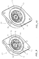
- FIGURES 1 and 4 best illustrate that the micro-fluidic valve apparatus 29, in one specific embodiment, is a rotor-type valve incorporating a rotor device 37 and a stator device 38 upon which the tubing interface assembly 20 is fluidly coupled to.
- the rotor device 37 and the stator device 38 are supported in an actuator assembly 40 which in turn is coupled to a rotor drive assembly 41.
- the actuator assembly 40 includes a housing 41 which defines an opening 42 upon which the stator device 38 is disposed.
- a relatively planar backside disk surface 43 of the stator device 38 is exposed in the housing opening 42 upon which the tubing interface assembly 20 cooperatively mounts.
- the tube port 22 of the tube apparatus 23 is fluidly aligned with a corresponding fluid communication port 45 defined in the proximal disk surface 43 of the stator device.
- the elastomeric ferrule device 24 is compressed between this proximal stator disk surface 43, on one side, and the rigid support ring 30 on the other side.
- each support ring 30 is further compressed against a corresponding cup-shaped recess, in accordance with the present invention, simultaneously forming a fluid-tight seal between the tube port 22 and the fluid communication port 45.
- corresponding multiple points are created to channel both inlet and outlet flow to the macro-fluidic environment.
- a quick mount tubing interface assembly is provided for a micro-fluidic valve apparatus that eliminates the prior art fluidic sealing interfaces that require external threaded features on the ferrule fitting and/or internal threaded feature in the cap member itself.
- the absence of such threaded features not only reduce production costs, but achieve simple and simultaneous fluidic continuity between the respective tube port 22 of the respective tube apparatus 23 and the corresponding fluid communication port 45 on the stator disk surface 43.
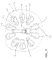
- the cap member further defines one or more petal-shaped slots 46.
- Each slot corresponds to, and is in fluid communication with, a respective tube receiving passage 35 thereof.
- the respective petal-shaped slots 46 each include a larger diameter ferrule passage portion 47, on one side, and taper down to the smaller diameter tube receiving passage 35 on an opposite end thereof (at least on the exterior surface side of the cap member).
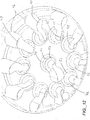
- each elastomeric ferrule device 24 is to be initially axially aligned with, and subsequently passes or slides through the larger diameter ferrule passage portion 47 from the proximal disk surface 43 side of the cap member.
- the ferrule passage portion 47 thus, is sized and dimensioned to slideably receive the transverse cross-sectional dimension of the elastomeric ferrule device 24 therethrough.
- the tube receiving passage 35 is more specifically sized and dimensioned to enable lateral friction fit, or press fit snap, receipt ( FIGURES 9 and 11 ).
- Each tapered channel 48 and the tube receiving passage 35 of the petal-shaped slot 46 is sufficiently sized, dimensioned and toleranced to prevent passage of the larger diameter elastomeric ferrule (5) axially therethrough, thereby preventing the tubing interface assembly 20 from falling out.
- a proximal portion 50 of the elastomeric ferrule device 24 and/or the corresponding support ring 30 can be proximally received in the cup-shaped receiving recess 36.
- This cupped seat 36 formed in the underside interior surface 33 of the cap member, is sufficiently sized to enable partial axial receipt of the rigid support ring 30, as well as the proximal portion 50 of the elastomeric ferrule device therein, while at the same time provide structural support under compressive forces.
- each cup-shaped receiving recess 36 preferably mirror that of the exterior surface of the proximal portion of the elastomeric ferrule device 24, albeit slightly larger.
- each receiving recess 36 is defined by an interior cylindrical wall 51, and a distally facing compression shoulder 52. Accordingly, as the proximal portion of the elastomeric ferrule device 24 and the corresponding support ring 30 are axially withdrawn and seated in the receiving recess 36, axial support is provided as the ferrule proximal end abuts against the compression shoulder 52, while lateral support is provided by engagement between the side walls of the ferrule device and corresponding support ring with the cylindrical wall 51.
- each elastomeric ferrule device 24 is simultaneously fluid-tight sealed to and around the corresponding fluid communication port 45 of the disk surface 43.
- petal-shaped slots 46 allow the tube member 21 of the tubing interface assembly 20 to be easily removed and replaced.
- a larger fitting e.g. 1/4-28
- a macro-fluidic device e.g. pump, reservoir, waste
- Such a macro-fluidic fitting will most likely be too large to fit through the smaller diameter tube receiving passage 35 of the slotted cap member.
- the sizes of the elastomeric ferrule and petal features of the slotted cap are specifically designed to allow the elastomeric ferrule to engage into the petal feature and fit in the cupped seat of the slotted cap member.
- any size fitting of the customer's choice on one end of the tubing is allowed, using the proper adapters, while the other end contains the elastomeric ferrule device 24 described above.
- the tube apparatus 23 collectively includes the elastomeric ferrule device 24, rigid support ring 30 and the elongated tube member 21.
- a rigid ferrule device By substituting a rigid ferrule device with an elastomeric ferrule device, three purposes are served.
- the elastomeric ferrule device 24 is sized and dimensioned for axial passage through the ferrule passage portion 47 of the petal-shaped slot 46, enabling simple insertion and removal therefrom.
- the elastomeric ferrule device 24, together with the support ring 30 provides a fluid-tight pressure seal when the ferrule distal end 27 thereof is compressed against the proximal disk surface 43 of the stator device 38.
- the elastomeric ferrule device when the elastomeric ferrule device is compressed, an opposite a spring force is created by the body member 25 in its compressed state.
- the collective compression of the plurality of elastomeric ferrule devices during assembly and mounting of the slotted cap member to the housing 41 or actuator body, via bolts or screws 53, for example, generate the compression force necessary to create the fluid-tight seal.
- the elastomeric ferrule device may be compressed in the range of about 10% to about 70% of its original height.
- a single elastomeric ferrule device with a diameter in the range of about 2.54 mm to about 4.57 mm (about 0.100 inch to about 0.180 inch), and height in the range of about 0.51 mm to about 2.03 mm (about 0.02 inch to about 0.08 inch), can alone achieve a compression spring biasing force in the range from a few pounds to about 11.3 N.m (about 100 lbf).
- valve actuator body consists primarily of the valve or actuator housing 41, the rotor device and the stator disk device each of which butt against one another.
- a compressive force in the range of at least about 3.4 N.m (about 30 lbf) between the rotor face 54 and stator face 59, at the stator/rotor interface, is sufficient to create a fluid-tight seal when the rotor and stator device materials are either polymer or ceramic.
- elastomeric ferrule devices 23 when multiple fluid connections are desired, a balanced distribution of elastomeric ferrule devices 23 is necessary to achieve a uniform application of compression pressure. Such a non-uniform pressure profile may result in skewed loading across the rotor/stator interface which results in leakage between the rotor face and stator face. Accordingly, the distribution of elastomeric ferrule devices 23 should be symmetrical oriented around the disk surface 43, and the about a rotational axis of the valve actuator assembly 40.
- the complete micro-fluidic valve apparatus 29 is illustrated with the plurality of tubing interface assemblies 20(e.g., in FIGURE 6 a total of eleven interface assemblies 20 are required for a ten-position selector micro-fluidic valve) which are symmetrically distributed about the cap member 31 in a manner applying a substantially uniform pressure gradient against proximal disk surface 43 of the stator device 38, which in turn biases the stator face 59 into abutting contact against the rotor face 54 of the rotor device 37. In turn, a uniform leak-tight seal is formed at the rotor/stator interface.
- each elastomeric ferrule device 24 seals around the corresponding communication port 45 at the proximal disk surface 43 of the stator device 38 with a compression force that is a function of length or distance the elastomeric ferrule device is deflected when compressed between the support ring 30 and disk surface 43.
- the biasing spring force to some degree is dependent upon the elastomeric material, as well the total height compression thereof.
- the compression or clamping forces are applied by a minimum of two 4-40 UNC screws or bolts 53 passing through the slotted housing and secured into the actuator housing internally threaded holes. It will be appreciated, of course, that any conventional technique for mounting the cap member 31 to the housing 41 could be applied.
- this ring is preferably comprised of a metallic material such as stainless steel. It will be appreciated, of course, that other rigid materials can be utilized such as aluminum or high strength plastics.
- the support ring 30 Under compression, the support ring 30 axially transmits compressive forces from the cap member 31 to the elastomeric ferrule device 24. More particularly, as best shown in FIGURES 5 and 16 , a proximal end 55 of the support ring 30 contacts a respective distally facing compression shoulder 52 of the cap member that partially defines each cup-shaped receiving recess 36. In turn, the compression forces are transmitted axially through the support ring 30 and on to the distal end 56 thereof which abuts a proximally facing ring contact shoulder 57 formed in each elastomeric ferrule device.
- each rigid support ring 30 While one primary function of each rigid support ring 30 is to transmit the compressive forces from the cap member to the corresponding elastomeric ferrule device, another primary function is to provide a sufficient radial crimping force to the elastomeric ferrule device so that the axial position thereof along the corresponding tube member is maintained. Accordingly, during both mounting of the tubing interference assembly to the cap member, and during compression mounting of the cap member to the actuator assembly, the axial position of the respective ferrule device 40 is relatively sustained.
- the support ring is configured to extend radially around a crimp portion 58 of the elastomeric ferrule device, providing a sufficient, albeit minute crimp force.
- an interior crimp wall 60 of the support ring 30 is slightly tapered outwardly from the proximal end 55 to a slightly wider the distal end 56 thereof.
- FIGURE 16 best illustrates the slope of the taper of the interior crimp wall 60 relative to longitudinal axis of the support ring 30.
- the remaining distal compression portion 67 of the elastomeric ferrule device 24 provides the spring force when this portion is compressed between the distal end 56 of the support ring 30 and the proximal disk surface 43 of the stator device 38 when the cap member is mounted to the housing 41.
- the outer diameter of the support ring is sized relatively similar to that of the outer diameter of the compression or distal portion 67 of the ferrule device.
- the outer diameter of the distal compression portion 67 is greater than that of the crimp portion 58. The diametric difference, of course, defines the ring-shaped contact shoulder 57.
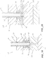
- FIGURES 17 and 18 an alternate embodiment is shown wherein the elastomeric ferrule device is supplanted with a ring or doughnut shaped elastomeric insert device 69 which is axially repositioned proximal to the rigid support ring 30.
- the elastomeric insert device 69 which of course provides the sealing spring force, is compressed between the distally facing compression shoulder 52 of the receiving recess 36 and the proximal end 55 of the support ring 30.
- a conventional standard flat bottom PEEK ferrule device 68 is provided for sealing against the proximal disk surface 43 of the stator device.
- the ring-shaped elastomeric insert device 69 applies a spring force biasing the flat bottom PEEK ferrule device 24' against the stator proximal disk surface 43, while in series collectively creating the sufficient compression force to seal the stator face 59 against the rotor face 54.
- a single piece elastomeric gasket 70 is disposed, and sandwiched, between a standard flat bottom PEEK ferrule device 68 and support ring 30, similar to the embodiment of FIGURES 17 and 18 , and the proximal disk surface 43.
- the thin gasket 70 includes properly aligned apertures 71 which correspond to the pattern in fluid communication ports 45 defined by the stator device dist surface 43.
- the standard flat bottom PEEK ferrule device compresses the gasket, via support ring 30, against the disk surface 43.
- the elastomeric gasket 70 forms the fluid tight seal between the tube port 22 of the tube apparatus 23 and the corresponding fluid communication port 45 of the proximal disk surface 43, and further collectively generates the spring force necessary to seal the stator face 59 to the rotor face 54.
- the gasket material is similar to the elastomeric ferrule material and may be manufactured from santoprene, polyethylene or fluoroelastomer compounds.
- FIGURE 21 illustrates yet another alternate embodiment which includes a conical-shaped stator device 38'.
- a conical-shaped stator device 38' incorporates angled, oval-shaped communication ports 72 at the stator face 59'.
- the bolt circle (approximately .460") is reduced from a larger diameter, where the elastomeric ferrule devices 23 seat, to a smaller diameter stator face 59'at the rotor/stator interface.
- the present invention is not limited in size, and thus a variety of tubing OD and/or ID can be selected. Currently many variations of Peek tubing exist with different ID and a constant OD of 1/16 th for instance.
- the design of the elastomeric ferrule device can be adjusted in dimension to accommodate larger or even smaller OD tubing.
- the slotted cap member similarly can also be adjustably sized and dimensioned to accommodate differing sizes of the elastomeric ferrule and number of slots.
- the ferrule includes a bore which is sized for receipt of the tube.
- the tubing interface further includes a cap member having an exterior surface, an opposed interior surface, and a tube receiving passage extending therethrough. The receiving passage is formed and dimensioned for axial sliding receipt of the tube member therethrough.
- the cap member further includes a cup-shaped receiving recess extending proximally from the interior surface, and is formed and dimensioned for axial receipt of the proximal end of the ferrule body member and the support ring.
Landscapes
- General Engineering & Computer Science (AREA)
- Engineering & Computer Science (AREA)
- Chemical & Material Sciences (AREA)
- Mechanical Engineering (AREA)
- Health & Medical Sciences (AREA)
- Life Sciences & Earth Sciences (AREA)
- General Physics & Mathematics (AREA)
- Physics & Mathematics (AREA)
- Clinical Laboratory Science (AREA)
- Analytical Chemistry (AREA)
- Biochemistry (AREA)
- General Health & Medical Sciences (AREA)
- Chemical Kinetics & Catalysis (AREA)
- Immunology (AREA)
- Pathology (AREA)
- Dispersion Chemistry (AREA)
- Multiple-Way Valves (AREA)
- Valve Housings (AREA)
- Infusion, Injection, And Reservoir Apparatuses (AREA)
Applications Claiming Priority (1)
| Application Number | Priority Date | Filing Date | Title |
|---|---|---|---|
| US201261701371P | 2012-09-14 | 2012-09-14 |
Publications (3)
| Publication Number | Publication Date |
|---|---|
| EP2708886A2 EP2708886A2 (en) | 2014-03-19 |
| EP2708886A3 EP2708886A3 (en) | 2016-06-22 |
| EP2708886B1 true EP2708886B1 (en) | 2019-04-24 |
Family
ID=49231250
Family Applications (1)
| Application Number | Title | Priority Date | Filing Date |
|---|---|---|---|
| EP13184349.2A Active EP2708886B1 (en) | 2012-09-14 | 2013-09-13 | Fluidic interface valve assembly with elastomeric ferrule device |
Country Status (4)
| Country | Link |
|---|---|
| US (1) | US9388930B2 (https=) |
| EP (1) | EP2708886B1 (https=) |
| JP (1) | JP6275429B2 (https=) |
| CA (1) | CA2826998A1 (https=) |
Families Citing this family (16)
| Publication number | Priority date | Publication date | Assignee | Title |
|---|---|---|---|---|
| DE102009022368C5 (de) | 2009-05-22 | 2020-12-17 | Dionex Softron Gmbh | Steckereinheit und Verbindungssystem für das Verbinden von Kapillaren, insbesondere für die Hochleistungsflüssigkeitschromatographie |
| JP6389328B2 (ja) * | 2014-09-23 | 2018-09-12 | アイデックス・ヘルス・アンド・サイエンス・リミテッド ライアビリティ カンパニーIdex Health & Science Llc | バネなし多位置マイクロ流体バルブアセンブリ |
| WO2016166089A1 (en) * | 2015-04-14 | 2016-10-20 | Keofitt A/S | Sampling device for withdrawing fluid samples from a fluid container |
| EP3163298B1 (en) | 2015-10-30 | 2023-12-27 | Dionex Softron GmbH | Capillary tube connection |
| WO2017161259A1 (en) * | 2016-03-17 | 2017-09-21 | Poietai Llc | Microfluidic on-chip storage devices |
| US10520477B2 (en) * | 2016-12-09 | 2019-12-31 | Idex Health & Science Llc | High pressure valve with multi-piece stator assembly |
| US11054054B2 (en) | 2016-12-09 | 2021-07-06 | Idex Health & Science Llc | High pressure valve with multi-piece stator assembly |
| US10384151B2 (en) | 2016-12-09 | 2019-08-20 | Idex Health & Science Llc | High pressure valve with two-piece stator assembly |
| JP6633776B2 (ja) | 2016-12-22 | 2020-01-22 | 株式会社島津製作所 | メカニカルシール装置 |
| WO2019186690A1 (ja) * | 2018-03-27 | 2019-10-03 | 株式会社島津製作所 | 水質分析計用マルチポートバルブ |
| CN108679260A (zh) * | 2018-07-05 | 2018-10-19 | 卡川尔流体科技(上海)有限公司 | 一种兼顾成本及优化残留的分离式换向阀/切换阀结构 |
| JP7381234B2 (ja) * | 2019-07-18 | 2023-11-15 | ニデックインスツルメンツ株式会社 | 弁体駆動装置 |
| GB2598113B (en) * | 2020-08-18 | 2024-11-20 | Agilent Technologies Inc | Fluidically coupling with elastic structure deformable by sealing element |
| US12320441B1 (en) * | 2021-02-08 | 2025-06-03 | Schivo Medical Limited | Centering electronic rotary valve |
| FR3152849A1 (fr) * | 2023-09-07 | 2025-03-14 | Khaled Abousaleh | Dispositif vanne rotative de précision |
| CN118189380B (zh) * | 2024-04-09 | 2024-09-10 | 珠海吉泰克物理科技有限公司 | 热泵室内机 |
Family Cites Families (18)
| Publication number | Priority date | Publication date | Assignee | Title |
|---|---|---|---|---|
| US3292652A (en) * | 1962-12-31 | 1966-12-20 | Gallone Cesare | High vacuum tight rotary valve |
| US3417605A (en) * | 1966-10-17 | 1968-12-24 | Phillips Petroleum Co | Valve sampling system for taking gaseous samples at about atmospheric pressure |
| US4243071A (en) * | 1978-08-23 | 1981-01-06 | Altex Scientific, Inc. | Sample injection valve |
| DE2941063A1 (de) * | 1978-10-20 | 1980-05-08 | Protimeter Ltd | Geraet zum messen des feuchtigkeitsgehaltes |
| JPS61157791U (https=) * | 1985-03-23 | 1986-09-30 | ||
| US4690437A (en) | 1986-02-27 | 1987-09-01 | Alltech Associates, Inc. | Low pressure fitting |
| US4969938A (en) * | 1990-01-03 | 1990-11-13 | The Perkin-Elmer Corporation | Fluid connector for microdevices |
| US5669637A (en) | 1996-05-29 | 1997-09-23 | Optimize Technologies, Inc. | Miniature fitting assembly for micro-tubing |
| US6095572A (en) * | 1998-01-20 | 2000-08-01 | Optimize Technologies, Inc. | Quarter turn quick connect fitting |
| US6319476B1 (en) | 1999-03-02 | 2001-11-20 | Perseptive Biosystems, Inc. | Microfluidic connector |
| US6575501B1 (en) * | 1999-03-05 | 2003-06-10 | Valco Instruments Company, Inc. | Tube sealing bushing |
| US6273478B1 (en) * | 1999-03-30 | 2001-08-14 | The Regents Of The University Of California | Microfluidic interconnects |
| US6267143B1 (en) * | 1999-06-29 | 2001-07-31 | Upchurch Scientific, Inc. | Selection valve with ferrule cluster |
| US20020155033A1 (en) * | 2000-10-06 | 2002-10-24 | Protasis Corporation | Fluid Separate conduit cartridge |
| US7014222B1 (en) * | 2001-03-05 | 2006-03-21 | Rheodyne, Llc | Tube connection system |
| GB0125074D0 (en) * | 2001-10-19 | 2001-12-12 | Amersham Biosciences Ab | Connector |
| WO2007009493A1 (en) * | 2005-07-19 | 2007-01-25 | Agilent Technologies, Inc. | Fluid conduits with molded plastic part |
| US7984933B2 (en) | 2008-02-28 | 2011-07-26 | Diba Industries, Inc. | Multi-use torque fitting and compressible ferrule |
-
2013
- 2013-09-12 US US14/025,415 patent/US9388930B2/en active Active
- 2013-09-13 JP JP2013190699A patent/JP6275429B2/ja active Active
- 2013-09-13 CA CA2826998A patent/CA2826998A1/en not_active Abandoned
- 2013-09-13 EP EP13184349.2A patent/EP2708886B1/en active Active
Non-Patent Citations (1)
| Title |
|---|
| None * |
Also Published As
| Publication number | Publication date |
|---|---|
| JP2014066359A (ja) | 2014-04-17 |
| US20140102568A1 (en) | 2014-04-17 |
| EP2708886A2 (en) | 2014-03-19 |
| US9388930B2 (en) | 2016-07-12 |
| EP2708886A3 (en) | 2016-06-22 |
| JP6275429B2 (ja) | 2018-02-07 |
| CA2826998A1 (en) | 2014-03-14 |
Similar Documents
| Publication | Publication Date | Title |
|---|---|---|
| EP2708886B1 (en) | Fluidic interface valve assembly with elastomeric ferrule device | |
| US6319476B1 (en) | Microfluidic connector | |
| JP6882480B2 (ja) | 多部品ステータアセンブリを伴う高圧弁 | |
| US6926313B1 (en) | High pressure capillary connector | |
| US8961906B2 (en) | Fluid connector devices and methods of making and using the same | |
| JP7362735B2 (ja) | 流体接続のための継手アセンブリ | |
| US8322374B2 (en) | Channel switching valve | |
| US20090121476A1 (en) | Microfluidic Bus for Interconnecting Multiple Fluid Conduits | |
| JP2015199028A (ja) | マイクロチャネルへの液体注入方法 | |
| CN103429894A (zh) | 多层隔膜 | |
| CN116057375A (zh) | 具有轴向角补偿件的阀 | |
| US20140105766A1 (en) | Face drive fluid pump | |
| WO2022108790A1 (en) | Multiport disconnect couplings | |
| US12569781B2 (en) | Fluidically coupling with elastic structure deformable by sealing element | |
| CN100556520C (zh) | 用于在非常高的压力下连续处理流体的均化器 | |
| CN116045062B (zh) | 液体流量控制器 | |
| JP2024162366A (ja) | マイクロ流体デバイス | |
| US20120074691A1 (en) | High pressure make and break fluidic seal system | |
| JP2025162168A (ja) | 配管接続構造 | |
| CN112730868A (zh) | 一种用于连续流动分析仪的进样系统 | |
| WO2008140706A1 (en) | High pressure make and break fluidic seal system |
Legal Events
| Date | Code | Title | Description |
|---|---|---|---|
| PUAI | Public reference made under article 153(3) epc to a published international application that has entered the european phase |
Free format text: ORIGINAL CODE: 0009012 |
|
| AK | Designated contracting states |
Kind code of ref document: A2 Designated state(s): AL AT BE BG CH CY CZ DE DK EE ES FI FR GB GR HR HU IE IS IT LI LT LU LV MC MK MT NL NO PL PT RO RS SE SI SK SM TR |
|
| AX | Request for extension of the european patent |
Extension state: BA ME |
|
| RIN1 | Information on inventor provided before grant (corrected) |
Inventor name: SERVIN, CARL |
|
| PUAL | Search report despatched |
Free format text: ORIGINAL CODE: 0009013 |
|
| AK | Designated contracting states |
Kind code of ref document: A3 Designated state(s): AL AT BE BG CH CY CZ DE DK EE ES FI FR GB GR HR HU IE IS IT LI LT LU LV MC MK MT NL NO PL PT RO RS SE SI SK SM TR |
|
| AX | Request for extension of the european patent |
Extension state: BA ME |
|
| RIC1 | Information provided on ipc code assigned before grant |
Ipc: B01L 3/00 20060101ALN20160519BHEP Ipc: G01N 30/20 20060101AFI20160519BHEP |
|
| STAA | Information on the status of an ep patent application or granted ep patent |
Free format text: STATUS: REQUEST FOR EXAMINATION WAS MADE |
|
| 17P | Request for examination filed |
Effective date: 20161221 |
|
| RBV | Designated contracting states (corrected) |
Designated state(s): AL AT BE BG CH CY CZ DE DK EE ES FI FR GB GR HR HU IE IS IT LI LT LU LV MC MK MT NL NO PL PT RO RS SE SI SK SM TR |
|
| STAA | Information on the status of an ep patent application or granted ep patent |
Free format text: STATUS: EXAMINATION IS IN PROGRESS |
|
| 17Q | First examination report despatched |
Effective date: 20180103 |
|
| GRAP | Despatch of communication of intention to grant a patent |
Free format text: ORIGINAL CODE: EPIDOSNIGR1 |
|
| STAA | Information on the status of an ep patent application or granted ep patent |
Free format text: STATUS: GRANT OF PATENT IS INTENDED |
|
| RIC1 | Information provided on ipc code assigned before grant |
Ipc: B01L 3/00 20060101ALN20181031BHEP Ipc: G01N 30/20 20060101AFI20181031BHEP |
|
| INTG | Intention to grant announced |
Effective date: 20181126 |
|
| GRAS | Grant fee paid |
Free format text: ORIGINAL CODE: EPIDOSNIGR3 |
|
| GRAA | (expected) grant |
Free format text: ORIGINAL CODE: 0009210 |
|
| STAA | Information on the status of an ep patent application or granted ep patent |
Free format text: STATUS: THE PATENT HAS BEEN GRANTED |
|
| AK | Designated contracting states |
Kind code of ref document: B1 Designated state(s): AL AT BE BG CH CY CZ DE DK EE ES FI FR GB GR HR HU IE IS IT LI LT LU LV MC MK MT NL NO PL PT RO RS SE SI SK SM TR |
|
| REG | Reference to a national code |
Ref country code: GB Ref legal event code: FG4D |
|
| REG | Reference to a national code |
Ref country code: CH Ref legal event code: EP |
|
| REG | Reference to a national code |
Ref country code: AT Ref legal event code: REF Ref document number: 1124727 Country of ref document: AT Kind code of ref document: T Effective date: 20190515 Ref country code: IE Ref legal event code: FG4D |
|
| REG | Reference to a national code |
Ref country code: DE Ref legal event code: R096 Ref document number: 602013054230 Country of ref document: DE |
|
| REG | Reference to a national code |
Ref country code: NL Ref legal event code: MP Effective date: 20190424 |
|
| REG | Reference to a national code |
Ref country code: LT Ref legal event code: MG4D |
|
| PG25 | Lapsed in a contracting state [announced via postgrant information from national office to epo] |
Ref country code: NL Free format text: LAPSE BECAUSE OF FAILURE TO SUBMIT A TRANSLATION OF THE DESCRIPTION OR TO PAY THE FEE WITHIN THE PRESCRIBED TIME-LIMIT Effective date: 20190424 |
|
| PG25 | Lapsed in a contracting state [announced via postgrant information from national office to epo] |
Ref country code: LT Free format text: LAPSE BECAUSE OF FAILURE TO SUBMIT A TRANSLATION OF THE DESCRIPTION OR TO PAY THE FEE WITHIN THE PRESCRIBED TIME-LIMIT Effective date: 20190424 Ref country code: HR Free format text: LAPSE BECAUSE OF FAILURE TO SUBMIT A TRANSLATION OF THE DESCRIPTION OR TO PAY THE FEE WITHIN THE PRESCRIBED TIME-LIMIT Effective date: 20190424 Ref country code: ES Free format text: LAPSE BECAUSE OF FAILURE TO SUBMIT A TRANSLATION OF THE DESCRIPTION OR TO PAY THE FEE WITHIN THE PRESCRIBED TIME-LIMIT Effective date: 20190424 Ref country code: SE Free format text: LAPSE BECAUSE OF FAILURE TO SUBMIT A TRANSLATION OF THE DESCRIPTION OR TO PAY THE FEE WITHIN THE PRESCRIBED TIME-LIMIT Effective date: 20190424 Ref country code: FI Free format text: LAPSE BECAUSE OF FAILURE TO SUBMIT A TRANSLATION OF THE DESCRIPTION OR TO PAY THE FEE WITHIN THE PRESCRIBED TIME-LIMIT Effective date: 20190424 Ref country code: NO Free format text: LAPSE BECAUSE OF FAILURE TO SUBMIT A TRANSLATION OF THE DESCRIPTION OR TO PAY THE FEE WITHIN THE PRESCRIBED TIME-LIMIT Effective date: 20190724 Ref country code: AL Free format text: LAPSE BECAUSE OF FAILURE TO SUBMIT A TRANSLATION OF THE DESCRIPTION OR TO PAY THE FEE WITHIN THE PRESCRIBED TIME-LIMIT Effective date: 20190424 Ref country code: PT Free format text: LAPSE BECAUSE OF FAILURE TO SUBMIT A TRANSLATION OF THE DESCRIPTION OR TO PAY THE FEE WITHIN THE PRESCRIBED TIME-LIMIT Effective date: 20190824 |
|
| PG25 | Lapsed in a contracting state [announced via postgrant information from national office to epo] |
Ref country code: GR Free format text: LAPSE BECAUSE OF FAILURE TO SUBMIT A TRANSLATION OF THE DESCRIPTION OR TO PAY THE FEE WITHIN THE PRESCRIBED TIME-LIMIT Effective date: 20190725 Ref country code: PL Free format text: LAPSE BECAUSE OF FAILURE TO SUBMIT A TRANSLATION OF THE DESCRIPTION OR TO PAY THE FEE WITHIN THE PRESCRIBED TIME-LIMIT Effective date: 20190424 Ref country code: LV Free format text: LAPSE BECAUSE OF FAILURE TO SUBMIT A TRANSLATION OF THE DESCRIPTION OR TO PAY THE FEE WITHIN THE PRESCRIBED TIME-LIMIT Effective date: 20190424 Ref country code: RS Free format text: LAPSE BECAUSE OF FAILURE TO SUBMIT A TRANSLATION OF THE DESCRIPTION OR TO PAY THE FEE WITHIN THE PRESCRIBED TIME-LIMIT Effective date: 20190424 Ref country code: BG Free format text: LAPSE BECAUSE OF FAILURE TO SUBMIT A TRANSLATION OF THE DESCRIPTION OR TO PAY THE FEE WITHIN THE PRESCRIBED TIME-LIMIT Effective date: 20190724 |
|
| REG | Reference to a national code |
Ref country code: AT Ref legal event code: MK05 Ref document number: 1124727 Country of ref document: AT Kind code of ref document: T Effective date: 20190424 |
|
| PG25 | Lapsed in a contracting state [announced via postgrant information from national office to epo] |
Ref country code: IS Free format text: LAPSE BECAUSE OF FAILURE TO SUBMIT A TRANSLATION OF THE DESCRIPTION OR TO PAY THE FEE WITHIN THE PRESCRIBED TIME-LIMIT Effective date: 20190824 |
|
| REG | Reference to a national code |
Ref country code: DE Ref legal event code: R097 Ref document number: 602013054230 Country of ref document: DE |
|
| PG25 | Lapsed in a contracting state [announced via postgrant information from national office to epo] |
Ref country code: SK Free format text: LAPSE BECAUSE OF FAILURE TO SUBMIT A TRANSLATION OF THE DESCRIPTION OR TO PAY THE FEE WITHIN THE PRESCRIBED TIME-LIMIT Effective date: 20190424 Ref country code: EE Free format text: LAPSE BECAUSE OF FAILURE TO SUBMIT A TRANSLATION OF THE DESCRIPTION OR TO PAY THE FEE WITHIN THE PRESCRIBED TIME-LIMIT Effective date: 20190424 Ref country code: RO Free format text: LAPSE BECAUSE OF FAILURE TO SUBMIT A TRANSLATION OF THE DESCRIPTION OR TO PAY THE FEE WITHIN THE PRESCRIBED TIME-LIMIT Effective date: 20190424 Ref country code: CZ Free format text: LAPSE BECAUSE OF FAILURE TO SUBMIT A TRANSLATION OF THE DESCRIPTION OR TO PAY THE FEE WITHIN THE PRESCRIBED TIME-LIMIT Effective date: 20190424 Ref country code: DK Free format text: LAPSE BECAUSE OF FAILURE TO SUBMIT A TRANSLATION OF THE DESCRIPTION OR TO PAY THE FEE WITHIN THE PRESCRIBED TIME-LIMIT Effective date: 20190424 Ref country code: AT Free format text: LAPSE BECAUSE OF FAILURE TO SUBMIT A TRANSLATION OF THE DESCRIPTION OR TO PAY THE FEE WITHIN THE PRESCRIBED TIME-LIMIT Effective date: 20190424 |
|
| PG25 | Lapsed in a contracting state [announced via postgrant information from national office to epo] |
Ref country code: SM Free format text: LAPSE BECAUSE OF FAILURE TO SUBMIT A TRANSLATION OF THE DESCRIPTION OR TO PAY THE FEE WITHIN THE PRESCRIBED TIME-LIMIT Effective date: 20190424 Ref country code: IT Free format text: LAPSE BECAUSE OF FAILURE TO SUBMIT A TRANSLATION OF THE DESCRIPTION OR TO PAY THE FEE WITHIN THE PRESCRIBED TIME-LIMIT Effective date: 20190424 |
|
| PLBE | No opposition filed within time limit |
Free format text: ORIGINAL CODE: 0009261 |
|
| STAA | Information on the status of an ep patent application or granted ep patent |
Free format text: STATUS: NO OPPOSITION FILED WITHIN TIME LIMIT |
|
| PG25 | Lapsed in a contracting state [announced via postgrant information from national office to epo] |
Ref country code: TR Free format text: LAPSE BECAUSE OF FAILURE TO SUBMIT A TRANSLATION OF THE DESCRIPTION OR TO PAY THE FEE WITHIN THE PRESCRIBED TIME-LIMIT Effective date: 20190424 |
|
| 26N | No opposition filed |
Effective date: 20200127 |
|
| PG25 | Lapsed in a contracting state [announced via postgrant information from national office to epo] |
Ref country code: MC Free format text: LAPSE BECAUSE OF FAILURE TO SUBMIT A TRANSLATION OF THE DESCRIPTION OR TO PAY THE FEE WITHIN THE PRESCRIBED TIME-LIMIT Effective date: 20190424 Ref country code: SI Free format text: LAPSE BECAUSE OF FAILURE TO SUBMIT A TRANSLATION OF THE DESCRIPTION OR TO PAY THE FEE WITHIN THE PRESCRIBED TIME-LIMIT Effective date: 20190424 |
|
| REG | Reference to a national code |
Ref country code: CH Ref legal event code: PL |
|
| PG25 | Lapsed in a contracting state [announced via postgrant information from national office to epo] |
Ref country code: IE Free format text: LAPSE BECAUSE OF NON-PAYMENT OF DUE FEES Effective date: 20190913 Ref country code: LI Free format text: LAPSE BECAUSE OF NON-PAYMENT OF DUE FEES Effective date: 20190930 Ref country code: LU Free format text: LAPSE BECAUSE OF NON-PAYMENT OF DUE FEES Effective date: 20190913 Ref country code: CH Free format text: LAPSE BECAUSE OF NON-PAYMENT OF DUE FEES Effective date: 20190930 |
|
| REG | Reference to a national code |
Ref country code: BE Ref legal event code: MM Effective date: 20190930 |
|
| PG25 | Lapsed in a contracting state [announced via postgrant information from national office to epo] |
Ref country code: BE Free format text: LAPSE BECAUSE OF NON-PAYMENT OF DUE FEES Effective date: 20190930 |
|
| PG25 | Lapsed in a contracting state [announced via postgrant information from national office to epo] |
Ref country code: FR Free format text: LAPSE BECAUSE OF NON-PAYMENT OF DUE FEES Effective date: 20190930 |
|
| PG25 | Lapsed in a contracting state [announced via postgrant information from national office to epo] |
Ref country code: CY Free format text: LAPSE BECAUSE OF FAILURE TO SUBMIT A TRANSLATION OF THE DESCRIPTION OR TO PAY THE FEE WITHIN THE PRESCRIBED TIME-LIMIT Effective date: 20190424 |
|
| PG25 | Lapsed in a contracting state [announced via postgrant information from national office to epo] |
Ref country code: HU Free format text: LAPSE BECAUSE OF FAILURE TO SUBMIT A TRANSLATION OF THE DESCRIPTION OR TO PAY THE FEE WITHIN THE PRESCRIBED TIME-LIMIT; INVALID AB INITIO Effective date: 20130913 Ref country code: MT Free format text: LAPSE BECAUSE OF FAILURE TO SUBMIT A TRANSLATION OF THE DESCRIPTION OR TO PAY THE FEE WITHIN THE PRESCRIBED TIME-LIMIT Effective date: 20190424 |
|
| PG25 | Lapsed in a contracting state [announced via postgrant information from national office to epo] |
Ref country code: MK Free format text: LAPSE BECAUSE OF FAILURE TO SUBMIT A TRANSLATION OF THE DESCRIPTION OR TO PAY THE FEE WITHIN THE PRESCRIBED TIME-LIMIT Effective date: 20190424 |
|
| PGFP | Annual fee paid to national office [announced via postgrant information from national office to epo] |
Ref country code: DE Payment date: 20250919 Year of fee payment: 13 |
|
| PGFP | Annual fee paid to national office [announced via postgrant information from national office to epo] |
Ref country code: GB Payment date: 20250918 Year of fee payment: 13 |