EP2708872A1 - Method and device for detecting moving objects in a gas flow - Google Patents
Method and device for detecting moving objects in a gas flow Download PDFInfo
- Publication number
- EP2708872A1 EP2708872A1 EP12006547.9A EP12006547A EP2708872A1 EP 2708872 A1 EP2708872 A1 EP 2708872A1 EP 12006547 A EP12006547 A EP 12006547A EP 2708872 A1 EP2708872 A1 EP 2708872A1
- Authority
- EP
- European Patent Office
- Prior art keywords
- light
- scattered
- signal strength
- light beam
- emitter
- Prior art date
- Legal status (The legal status is an assumption and is not a legal conclusion. Google has not performed a legal analysis and makes no representation as to the accuracy of the status listed.)
- Withdrawn
Links
Images

Classifications
-
- G—PHYSICS
- G01—MEASURING; TESTING
- G01N—INVESTIGATING OR ANALYSING MATERIALS BY DETERMINING THEIR CHEMICAL OR PHYSICAL PROPERTIES
- G01N21/00—Investigating or analysing materials by the use of optical means, i.e. using sub-millimetre waves, infrared, visible or ultraviolet light
- G01N21/17—Systems in which incident light is modified in accordance with the properties of the material investigated
- G01N21/47—Scattering, i.e. diffuse reflection
- G01N21/49—Scattering, i.e. diffuse reflection within a body or fluid
- G01N21/53—Scattering, i.e. diffuse reflection within a body or fluid within a flowing fluid, e.g. smoke
- G01N21/532—Scattering, i.e. diffuse reflection within a body or fluid within a flowing fluid, e.g. smoke with measurement of scattering and transmission
-
- G—PHYSICS
- G01—MEASURING; TESTING
- G01N—INVESTIGATING OR ANALYSING MATERIALS BY DETERMINING THEIR CHEMICAL OR PHYSICAL PROPERTIES
- G01N21/00—Investigating or analysing materials by the use of optical means, i.e. using sub-millimetre waves, infrared, visible or ultraviolet light
- G01N21/84—Systems specially adapted for particular applications
- G01N21/85—Investigating moving fluids or granular solids
-
- G—PHYSICS
- G01—MEASURING; TESTING
- G01N—INVESTIGATING OR ANALYSING MATERIALS BY DETERMINING THEIR CHEMICAL OR PHYSICAL PROPERTIES
- G01N21/00—Investigating or analysing materials by the use of optical means, i.e. using sub-millimetre waves, infrared, visible or ultraviolet light
- G01N21/17—Systems in which incident light is modified in accordance with the properties of the material investigated
- G01N21/47—Scattering, i.e. diffuse reflection
- G01N2021/4704—Angular selective
- G01N2021/4726—Detecting scatter at 90°
-
- G—PHYSICS
- G01—MEASURING; TESTING
- G01N—INVESTIGATING OR ANALYSING MATERIALS BY DETERMINING THEIR CHEMICAL OR PHYSICAL PROPERTIES
- G01N21/00—Investigating or analysing materials by the use of optical means, i.e. using sub-millimetre waves, infrared, visible or ultraviolet light
- G01N21/84—Systems specially adapted for particular applications
- G01N21/85—Investigating moving fluids or granular solids
- G01N2021/8578—Gaseous flow
Definitions
- the invention relates to an apparatus and a method for monitoring a gas flow.
- drift eliminators such as e.g. baffle-based separators such as lamellar separators, knitted fabric separators, gravity separators or cyclone separators are used. If the mist eliminator does not work properly, it will result in dripping. This can lead to serious damage to subsequent parts of the system, which rely on a gas flow without liquid content.
- the invention therefore has the object to provide a simple, effective way to monitor a gas flow, which allows a direct detection of objects moving in the gas stream.
- the device according to the invention for monitoring a gas stream comprises a pipe or a container for passing the gas stream, a light emitter for emitting light and a light sensor and a scattered light detector.
- the light sensor and the scattered light detector are each adapted to detect a signal strength of light when receiving the light, i. when the light falls on the light sensor or the scattered light detector.
- the light sensor is aligned to receive a light emitted by the light emitter, the tube or the container by crossing, unscattered light beam;
- the intersecting can take place, for example, in a direction orthogonal to a longitudinal axis of the tube or container, or obliquely to a longitudinal axis or in the direction of a longitudinal axis.
- the scattered light detector is aligned to receive a scattered light beam portion of a light beam emitted from the light emitter.
- the light emitter, the light sensor and the scattered light detector of the device according to the invention are thus preferably oriented such that a light beam emitted by the light emitter, if not scattered (ie deflected), can cross the tube or container and fall directly to the light sensor, but not on the scattered light detector. If, however, a light beam emitted by the light emitter at least Partially scattered on an object in the gas flow in the direction of the scattered light detector, a scattered portion of the light beam falls on the scattered light detector.
- the method of monitoring a gas stream comprises irradiating the gas stream with a light beam, measuring (eg with a light sensor) a signal strength of an unscattered (ie undeflected) portion of the light beam (hereinafter referred to as "first signal strength"), and measuring (eg with a scattered light detector) a scattered light signal strength as a signal strength of a scattered fraction of the light beam (the scattered light signal strength can therefore also be zero).
- Both the scattered light detector and the light sensor may be light detectors, which may also be identical or of the same type: the different designations have been chosen here only for better distinctness.
- the scattered-light detector can be aligned with respect to one or more further light emitters, if present, and act like the light sensor with respect to the first light emitter, so that it can detect a signal strength of an unscattered light beam emitted by the further light emitter.
- the light sensor can be arranged and arranged such that it can detect a scattered light component of another, for example the further light emitter. It is also possible for a total of more than two light sensors, each of which can also function as scattered-light detectors, to be used.
- the moving object may be a solid particle (e.g., an ash particle) or a liquid droplet, especially a water droplet.
- the device may be part of an air separation plant and / or a direct contact cooler, and the process may be part of an air cooling and / or air separation process.
- the gas stream can thus be monitored according to the invention by detecting a scattering of an emitted light beam.
- the light beam is therefore examined from two sides, namely with regard to its signal strength on the one hand in its original, undisrupted direction and on the other hand in a scattered direction.
- the degree of signal attenuation according to the invention is not unique Indicator for an object. Rather, it is also examined whether the light beam is scattered.
- the device of the invention is significantly less sensitive to deposits or age-related deterioration than conventional photocells. The same applies to the method according to the invention.
- the scattered light detector measures or determines a scattered light signal strength of a light beam component scattered towards it.
- the scattered light detector may thus distinguish between light incident thereon, which is a scattered portion of a light beam emitted by the light emitter, and other incident light (e.g., scattered light directly or from another emitter).
- the device can reliably detect scattering and thus recognize an object moving with the gas flow.
- the signal strengths detected by the light sensor and by the scattered-light detector are each compared with threshold values.
- the signal strength measured by the light sensor also referred to below as “first signal strength”
- the signal strength measured by the light sensor can be compared with at least one predetermined direct signal threshold value, and / or the scattered light signal strength measured by the scattered light detector with a predetermined scatter signal threshold value.
- the device may comprise a computing unit that can make this comparison or these comparisons.
- a preferred embodiment of the method includes predetermining the direct signal and / or the spread signal threshold.
- the direct signal threshold may be (or have been) predetermined so that the signal strength of an unscattered portion of a light beam is below the direct signal threshold only if the light beam has passed an object (eg, a drop of liquid) of a certain minimum size or a minimum number of objects.
- the device may be configured to detect the presence of an object in the gas stream when both the first signal strength falls below the predetermined direct signal threshold and the stray light signal strength exceeds the predetermined leakage signal threshold.
- the meaning of the terms "fall below” and “transcend” can each be extended to include equality.
- the presence of an object or a predetermined minimum number or density of objects in the gas stream may be signaled to a user, for example by an audible alarm or a visual indication (e.g., in the form of a light or display).
- the presence may be used as an electrical signal or as information in a computing unit, for example in an analysis algorithm or in an automatic response program such as e.g. an emergency program.
- the device thus permits an automated or user-initiated reaction to a process measured inside the tube or container.
- the user or the automatic reaction program can, for example, initiate a shutdown of a system in which the device is incorporated or change a change in at least one parameter determines the function of the system.
- the arithmetic unit can then analyze the temporal behavior of the two light intensities, for example in order to determine or approximate a number or density of objects moving with the gas flow.
- the arithmetic unit can include suitable analysis software.
- the light emitter preferably has a positive opening angle for emitting light, so that it can simultaneously emit light beams in different directions.
- the light sensor preferably covers the entire area illuminated by the light emitter. Thus, with the light emitter, a larger space in the tube or container can be illuminated and monitored, as if the light emitter only in one only direction emits light.
- the opening angle may be, for example, 10 °, 15 ° or 20 °.
- the light emitter is a first light emitter and the device has at least one second light emitter. This can be set up to emit light of a different frequency, offset in time and / or coded differently than the first light emitter.
- the second light emitter and the scattered light detector are aligned with each other such that an unscattered light beam emitted by the second light emitter can fall on the aforementioned scattered light detector.
- the scattered-light detector can then detect, on the one hand, directly incident light from the second light emitter and, on the other hand, scattered light emitted by the first light emitter.
- the scattered-light detector can act in the same way with respect to the second light-emitter as the light sensor with respect to the first light-emitter.
- the scattered light detector can preferably distinguish the respectively detected light and thus detect, in particular, changes in the respective signal strengths of scattered light of the first and unscattered light of the second light emitter and, if appropriate, interpret them according to the above-described ways, for example with corresponding ones Compare thresholds.
- This embodiment offers the particular advantage of monitoring a larger space in the pipe or container with a relatively small number of required detectors.
- At least one second light emitter, light sensor and scattered-light detector can be provided, which are arranged to one another as described above for the (first) light emitter, the (first) light sensor and the (first) light detector.
- First and second light emitters, light sensors and scattered light detectors may be staggered around a circumference (e.g., on a common plane orthogonal to a longitudinal axis) of the tube or container, or distributed over the length thereof. As a result, a comprehensive monitoring of the interior of the pipe or container is possible.
- Advantageous is a use of the device or an application of the method for monitoring and / or regulating a mist eliminator, a direct contact cooler; an evaporator, where in incomplete evaporation drops are entrained; a mass separator (for example a cyclone separator); an electrostatic precipitator; a solids filter (eg, a soot filter) and / or a gas scrubber.
- a mass separator for example a cyclone separator
- electrostatic precipitator for example a solids filter (eg, a soot filter) and / or a gas scrubber.
- the apparatus may be used to detect solid particles (such as ash particles) in gas phases, for example, when used to monitor and / or control said filters.
- solid particles such as ash particles
- FIG. 1A schematically a cross-section of a tube or container 1 is shown, on which a light emitter 10, a light sensor 11 and a scattered light detector 12 are arranged.
- a gas stream may be passed through the pipe or container perpendicular to the illustrated cross-sectional plane.
- the light emitter 10 shown, the light sensor 11 and the scattered light detector 12 are arranged relative to one another so that an unexcited light beam 100, 101, 102 emitted by the light emitter can cross the tube or container and fall directly onto the light sensor 11, but not onto the scattered light detector ,
- the light emitter 10 has an aperture angle ⁇ , which is the maximum possible angle between two light beams emitted by the light emitter. The entire illuminated by the light emitter area is covered by the light sensor 11, which can detect the signal strength of the incident light.
- FIG 1 B is a behavior of the light beam 100 in the in Figure 1A shown arrangement when it encounters in its course on an object 4:
- a proportion 101 of Light beam penetrates the object 2 unscrupulously and strikes the light sensor 11.
- the signal strength of the portion 101 is thereby reduced in comparison to the signal strength of the original light beam 100; the light sensor 11 measures the remaining signal strength and preferably compares it with a direct signal threshold.
- Additional portions of the light beam 100 are scattered in different directions.
- a portion 102 of the light beam is scattered in the direction of the scattered light detector 12.
- the portion 102 falls on the scattered light detector, which can now measure the signal strength of the portion 102, and preferably can compare with a Streusignalschwellwert.
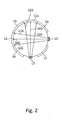
- FIG. 2 an embodiment of the present invention is shown in which in addition to the first light emitter 10, a second light emitter 17 is still present.
- the second light emitter 17 is arranged to emit light beams 200, 210, 220 that cross the tube and, if not scattered by an intermediate object, strike the light sensor 12A.
- the light sensor 12A may function as the scattered light detector 12 with respect to the light emitter 10. In this case, it may preferably be arranged between the light beams 17, unscattered light beams 200, 210, 220 and, if necessary, scattered light beam components (as in FIG FIG. 1B shown light beam portion 102) distinguished by the first light emitter 10 light beams 100, 101, 102 differ. This can be achieved by suitable modulation or temporal displacement of the emitted light beams.
- the device shown has further light detectors 13, 14, 15 and 16 which, with the above designations with respect to the light emitters 10 and 17, can each be set up as a light sensor and / or as a scattered-light detector.
Landscapes
- Physics & Mathematics (AREA)
- Health & Medical Sciences (AREA)
- Life Sciences & Earth Sciences (AREA)
- Chemical & Material Sciences (AREA)
- Analytical Chemistry (AREA)
- Biochemistry (AREA)
- General Health & Medical Sciences (AREA)
- General Physics & Mathematics (AREA)
- Immunology (AREA)
- Pathology (AREA)
- Investigating Or Analysing Materials By Optical Means (AREA)
Abstract
Description
Die Erfindung betrifft eine Vorrichtung und ein Verfahren zum Überwachen eines Gasstroms.The invention relates to an apparatus and a method for monitoring a gas flow.
In Direktkontaktapparaten wie z.B. Kolonnen oder Packungssäulen, aber auch bei Siedevorgängen stehen gasförmige und flüssige Phasen in direktem Kontakt. Dabei kann es zum Tropfenmitriss, also einem Mitführen von kleinen Tröpfchen oder Nebel durch den Gasstrom kommen. Dieses Austragen der flüssigen Phase ist in der Regel unerwünscht. Zur Verhinderung des Tropfenmitrisses kommen Tropfenabscheider, wie z.B. prallblechbasierte Abscheider wie Lamellenabscheider, Gestrickabscheider, Schwerkraftabscheider oder Zyklonabscheider, zum Einsatz. Arbeitet der Tropfenabscheider nicht ordnungsgemäß, kommt es zu einem Tropfenmitriss. Dies kann zu schwerwiegenden Schäden an dahinter folgenden Anlagenteilen führen, die auf eine Gasströmung ohne Flüssigkeitsanteil angewiesen sind.In direct contact devices, such as Columns or packing columns, but also in boiling processes are gaseous and liquid phases in direct contact. This can lead to droplet leakage, that is to say a small droplet or mist entrained by the gas flow. This discharge of the liquid phase is generally undesirable. To prevent dripping, drift eliminators such as e.g. baffle-based separators such as lamellar separators, knitted fabric separators, gravity separators or cyclone separators are used. If the mist eliminator does not work properly, it will result in dripping. This can lead to serious damage to subsequent parts of the system, which rely on a gas flow without liquid content.
Eine regelmäßige Überwachung des Abscheiders, also eine Detektion von Tropfenmitriss, kommt nur bei Gestrickabscheidern zum Einsatz. Dabei macht man sich die Eigenschaft des Drahtgestricks zunutze, dass sich vor einem starken Anstieg eines Wassermitrisses aus dem Gestrick heraus zuerst eine Wassersprudelschicht im unteren Bereich des Gestricks ausbildet. Diese Wassersprudelschicht erhöht den Druckverlust der Luft beim Durchströmen des Gestricks proportional zur Höhe der Sprudelschicht.A regular monitoring of the separator, so a detection of Tropfenmitriss, is used only in knitted fabric. In doing so, one makes use of the property of the wire mesh that, before a strong increase in water torridity, a water bubble layer initially forms out of the knitted fabric in the lower region of the knitted fabric. This water bubbling layer increases the pressure loss of the air as it flows through the knitted fabric in proportion to the height of the bubble layer.
Die indirekte Überwachung von Wassermitriss über den Druckverlust weist den Nachteil auf, dass Schaum, der durch einen Gestrickabscheider nicht zurückgehalten werden kann, keinen nennenswerten Druckverlustanstieg zur Folge hat. Bei einer Entstehung von Schaum ist die Kontrolle daher unzureichend. Darüber hinaus können sich im Laufe der Zeit Verschmutzungen im Gestrick ablagern, beim Einsatz von Wasser beispielsweise Algen oder Kalk. Der Druckverlust über das Gestrick steigt dabei langsam und kontinuierlich an. Die Mitrissmenge erhöht sich mit zunehmender Verschmutzung des Gestricks, so dass sich ein Alarmgrenzwert für den Druckverlust stets nur vorübergehend angeben lässt. Bei anderen Typen von Abscheidern ist keine derart einfach zu realisierende Überwachung ihrer Funktion möglich. Hier können nur aus anderen Prozessparametern, wie z.B. der Temperatur hinter dem Abscheider oder dem Verhalten des Mediums in weiteren Verfahrensschritten, Rückschlüsse auf einen eventuellen Tropfenmitriss gezogen werden. Diese Methoden sind aber sehr fehleranfällig, weil auch eine Vielzahl anderer Gründe zu den genannten Abweichungen der Prozessparameter führen kann.The indirect monitoring of water torridity over the pressure loss has the disadvantage that foam which can not be retained by a knit separator does not result in a significant increase in pressure loss. In the case of formation of foam, the control is therefore insufficient. In addition, dirt can accumulate in the fabric over time, with the use of water, for example, algae or lime. The pressure loss over the fabric increases slowly and continuously. The amount of entrainment increases with increasing contamination of the knitted fabric so that a pressure loss alarm limit can always be given only temporarily. For other types of separators, none is so easy to use Realizing monitoring of their function possible. In this case, conclusions can only be drawn from any other process parameters, such as the temperature behind the separator or the behavior of the medium in further process steps, for a possible drop infiltration. However, these methods are very error-prone, because a variety of other reasons can lead to the mentioned deviations of the process parameters.
Zur direkten Erkennung von Tropfenmitriss in einem Gasstrom sind bislang nur aufwendige optische Messverfahren und -vorrichtungen mit rechnergestützer Mustererkennung kommerziell erhältlich. Die Erfindung hat daher die Aufgabe, eine einfache, effektive Möglichkeit zur Überwachung eines Gasstroms bereitzustellen, die ein direktes Erkennen von sich im Gasstrom bewegenden Objekten erlaubt.For the direct detection of droplets in a gas stream, only expensive optical measuring methods and devices with computer-aided pattern recognition have hitherto been commercially available. The invention therefore has the object to provide a simple, effective way to monitor a gas flow, which allows a direct detection of objects moving in the gas stream.
Die Aufgabe wird gelöst durch eine Vorrichtung und ein Verfahren mit den Merkmalen der unabhängigen Patentansprüche.The object is achieved by a device and a method having the features of the independent claims.
Die erfindungsgemäße Vorrichtung zum Überwachen eines Gasstroms umfasst ein Rohr oder einen Behälter zum Durchleiten des Gasstroms, einen Lichtemitter zum Aussenden von Licht sowie einen Lichtsensor und einen Streulichtdetektor. Der Lichtsensor und der Streulichtdetektor sind jeweils geeignet, eine Signalstärke von Licht zu erfassen, wenn sie das Licht empfangen, d.h. wenn das Licht auf den Lichtsensor bzw. den Streulichtdetektor fällt.The device according to the invention for monitoring a gas stream comprises a pipe or a container for passing the gas stream, a light emitter for emitting light and a light sensor and a scattered light detector. The light sensor and the scattered light detector are each adapted to detect a signal strength of light when receiving the light, i. when the light falls on the light sensor or the scattered light detector.
Der Lichtsensor ist dabei zum Empfangen eines vom Lichtemitter ausgesandten, das Rohr oder den Behälter durchkreuzenden, ungestreuten Lichtstrahls ausgerichtet; das Durchkreuzen kann dabei beispielsweise in einer Richtung orthogonal zu einer Längsachse des Rohrs oder Behälters erfolgen, oder schräg zu einer Längsachse oder in Richtung einer Längsachse. Der Streulichtdetektor ist zum Empfangen eines gestreuten Lichtstrahlanteils eines vom Lichtemitter ausgesandten Lichtstrahls ausgerichtet.The light sensor is aligned to receive a light emitted by the light emitter, the tube or the container by crossing, unscattered light beam; The intersecting can take place, for example, in a direction orthogonal to a longitudinal axis of the tube or container, or obliquely to a longitudinal axis or in the direction of a longitudinal axis. The scattered light detector is aligned to receive a scattered light beam portion of a light beam emitted from the light emitter.
Der Lichtemitter, der Lichtsensor und der Streulichtdetektor der erfindungsgemäßen Vorrichtung sind also vorzugsweise so ausgerichtet, dass ein vom Lichtemitter ausgesandter Lichtstrahl, wenn er nicht gestreut (d.h. abgelenkt) wird, das Rohr oder den Behälter durchkreuzen und direkt auf den Lichtsensor fallen kann, nicht aber auf den Streulichtdetektor. Wird hingegen ein vom Lichtemitter ausgesandter Lichtstrahl mindestens teilweise an einem Objekt im Gasstrom in die Richtung des Streulichtdetektors gestreut, fällt ein gestreuter Anteil des Lichtstrahls auf den Streulichtdetektor.The light emitter, the light sensor and the scattered light detector of the device according to the invention are thus preferably oriented such that a light beam emitted by the light emitter, if not scattered (ie deflected), can cross the tube or container and fall directly to the light sensor, but not on the scattered light detector. If, however, a light beam emitted by the light emitter at least Partially scattered on an object in the gas flow in the direction of the scattered light detector, a scattered portion of the light beam falls on the scattered light detector.
Das erfindungsgemäße Verfahren zum Überwachen eine Gasstroms umfasst ein Bestrahlen des Gasstroms mit einem Lichtstrahl, ein Messen (z.B. mit einem Lichtsensor) einer Signalstärke eines ungestreuten (d.h. nicht abgelenkten) Anteils des Lichtstrahls (die im folgenden als "erste Signalstärke" bezeichnet wird), und ein Messen (z.B. mit einem Streulichtdetektor) einer Streulichtsignalstärke als einer Signalstärke eines gestreuten Anteils des Lichtstrahls (die Streulichtsignalstärke kann also auch Null sein).The method of monitoring a gas stream according to the invention comprises irradiating the gas stream with a light beam, measuring (eg with a light sensor) a signal strength of an unscattered (ie undeflected) portion of the light beam (hereinafter referred to as "first signal strength"), and measuring (eg with a scattered light detector) a scattered light signal strength as a signal strength of a scattered fraction of the light beam (the scattered light signal strength can therefore also be zero).
Sowohl beim Streulichtdetektor als auch beim Lichtsensor kann es sich um Lichtdetektoren handeln, die auch baugleich oder von demselben Typ sein können: Die unterschiedlichen Bezeichnungen wurden hier nur zur besseren Unterscheidbarkeit gewählt. Insbesondere kann der Streulichtdetektor in Bezug auf einen oder mehrere ggf. vorhandenen weiteren Lichtemitter ausgerichtet sein und fungieren wie der Lichtsensor bezüglich des ersten Lichtemitters, so dass er also eine Signalstärke eines vom weiteren Lichtemitter ausgesandten, ungestreuten Lichtstrahls erfassen kann. Analog kann der Lichtsensor so angeordnet und eingerichtet sein, dass er einen Streulichtanteil eines anderen, beispielsweise des weiteren Lichtemitters erfassen kann. Es können auch insgesamt mehr als zwei Lichtsensoren, die jeweils auch als Streulichtdetektoren fungieren können, zum Einsatz kommen.Both the scattered light detector and the light sensor may be light detectors, which may also be identical or of the same type: the different designations have been chosen here only for better distinctness. In particular, the scattered-light detector can be aligned with respect to one or more further light emitters, if present, and act like the light sensor with respect to the first light emitter, so that it can detect a signal strength of an unscattered light beam emitted by the further light emitter. Analogously, the light sensor can be arranged and arranged such that it can detect a scattered light component of another, for example the further light emitter. It is also possible for a total of more than two light sensors, each of which can also function as scattered-light detectors, to be used.
Das sich bewegende Objekt kann beispielsweise ein festes Partikel (z.B. ein Aschepartikel) oder ein Flüssigkeitströpfchen, insbesondere ein Wassertröpfchen sein. Die Vorrichtung kann Teil einer Luftzerlegungsanlage und/oder eines Direktkontaktkühlers sein, und das Verfahren kann Teil eines Luftkühlungs- und/oder Luftzerlegungsprozesses sein.For example, the moving object may be a solid particle (e.g., an ash particle) or a liquid droplet, especially a water droplet. The device may be part of an air separation plant and / or a direct contact cooler, and the process may be part of an air cooling and / or air separation process.
Der Gasstrom kann somit erfindungsgemäß überwacht werden, indem eine Streuung eines ausgesandten Lichtstrahls erfasst wird. Der Lichtstrahl wird also von zwei Seiten her untersucht, nämlich im Hinblick auf seine Signalstärke einerseits in seine ursprüngliche, ungestreute Richtung und andererseits in eine gestreute Richtung. Im Gegensatz zu einer konventionellen Einweg-Lichtschranke, bei der aus einer Schwächung eines direkten Lichtsignals auf ein zwischen Sender und Empfänger vorhandenes Objekt geschlossen wird, ist der Grad einer Signalschwächung erfindungsgemäß nicht einziges Indiz für ein Objekt. Vielmehr wird darüber hinaus geprüft, ob der Lichtstrahl gestreut wird. Aufgrurid dieser doppelten Prüfung ist die erfindungsgemäße Vorrichtung deutlich weniger empfindlich gegenüber Ablagerungen oder altersbedingten Verschlechterungen als herkömmliche Lichtschranken. Entsprechendes gilt für das erfindungsgemäße Verfahren.The gas stream can thus be monitored according to the invention by detecting a scattering of an emitted light beam. The light beam is therefore examined from two sides, namely with regard to its signal strength on the one hand in its original, undisrupted direction and on the other hand in a scattered direction. In contrast to a conventional one-way photoelectric sensor in which it is concluded from a weakening of a direct light signal to an existing between the transmitter and receiver object, the degree of signal attenuation according to the invention is not unique Indicator for an object. Rather, it is also examined whether the light beam is scattered. Aufgrurid this double test, the device of the invention is significantly less sensitive to deposits or age-related deterioration than conventional photocells. The same applies to the method according to the invention.
In einer bevorzugten Ausführungsform misst oder bestimmt der Streulichtdetektor eine Streulichtsignalstärke eines zu ihm hin gestreuten Lichtstrahlanteils. Vorzugsweise kann der Streulichtdetektor damit gegebenenfalls zwischen auf ihn fallendem Licht, das ein gestreuter Anteil eines vom Lichtemitter ausgesandten Lichtstrahls ist, und sonstigem einfallenden Licht (z.B. direkt oder von einem anderen Emitter stammendem, gestreutem Licht) unterscheiden. Damit kann die Vorrichtung eine Streuung zuverlässig erfassen und so ein sich mit dem Gasstrom bewegendes Objekt erkennen.In a preferred embodiment, the scattered light detector measures or determines a scattered light signal strength of a light beam component scattered towards it. Preferably, the scattered light detector may thus distinguish between light incident thereon, which is a scattered portion of a light beam emitted by the light emitter, and other incident light (e.g., scattered light directly or from another emitter). Thus, the device can reliably detect scattering and thus recognize an object moving with the gas flow.
Vorzugsweise werden die vom Lichtsensor und vom Streulichtdetektor erfassten Signalstärken jeweils mit Schwellwerten verglichen. So kann die vom Lichtsensor gemessene Signalstärke (im Folgenden auch als "erste Signalstärke" bezeichnet) mit mindestens einem vorbestimmten Direktsignalschwellwert verglichen werden, und/oder die vom Streulichtdetektor gemessene Streulichtsignalstärke mit einem vorbestimmten Streusignalschwellwert. Die Vorrichtung kann eine Recheneinheit umfassen, die diesen Vergleich bzw. diese Vergleiche vornehmen kann.Preferably, the signal strengths detected by the light sensor and by the scattered-light detector are each compared with threshold values. Thus, the signal strength measured by the light sensor (also referred to below as "first signal strength") can be compared with at least one predetermined direct signal threshold value, and / or the scattered light signal strength measured by the scattered light detector with a predetermined scatter signal threshold value. The device may comprise a computing unit that can make this comparison or these comparisons.
Vermöge der Schwellwerte können Störfunktionen vermieden werden und eine gewünschte Genauigkeit der Erfassung eventuell vorhandener, sich mit dem Gasstrom bewegender Objekte eingestellt werden. Die Vorbestimmung des Direktsignal- und/oder des Streusignalschwellwerts kann vorzugsweise durch einen Anwender oder einen Automat erfolgen; die Vorrichtung kann dazu erforderliche Mittel umfassen. So ist eine Anpassung an eine gewünschte Genauigkeit oder an ein Alter der Vorrichtung möglich. Entsprechend umfasst eine bevorzugte Ausführungsform des Verfahrens ein Vorbestimmen des Direktsignal- und/oder des Streusignalschwellwerts. Beispielsweise kann der Direktsignalschwellwert so (niedrig) vorbestimmt werden oder worden sein, dass die Signalstärke eines ungestreuten Anteils eines Lichtstrahls nur dann unterhalb des Direktsignalschwellwerts liegt, wenn der Lichtstrahl ein Objekt (z.B. einen Flüssigkeitstropfen) einer gewissen Mindestgröße oder eine Mindestanzahl von Objekten passiert hat.By virtue of the threshold values, interference functions can be avoided and a desired accuracy of detection of any objects moving with the gas flow can be set. The predetermination of the direct signal and / or the stray signal threshold value can preferably be carried out by a user or an automaton; the device may comprise means required for this purpose. Thus, an adaptation to a desired accuracy or to an age of the device is possible. Accordingly, a preferred embodiment of the method includes predetermining the direct signal and / or the spread signal threshold. For example, the direct signal threshold may be (or have been) predetermined so that the signal strength of an unscattered portion of a light beam is below the direct signal threshold only if the light beam has passed an object (eg, a drop of liquid) of a certain minimum size or a minimum number of objects.
Die Vorrichtung kann eingerichtet sein, auf ein Vorhandensein eines Objekts im Gasstrom zu schließen, wenn sowohl die erste Signalstärke den vorbestimmten Direktsignalschwellwert unterschreitet als auch die Streulichtsignalstärke den vorbestimmten Streusignalschwellwert überschreitet. Die Bedeutung der Begriffe "unterschreiten" und "überschreiten" kann dabei jeweils so erweitert werden, dass sie Gleichheit einschließt.The device may be configured to detect the presence of an object in the gas stream when both the first signal strength falls below the predetermined direct signal threshold and the stray light signal strength exceeds the predetermined leakage signal threshold. The meaning of the terms "fall below" and "transcend" can each be extended to include equality.
Das Vorhandensein eines Objekts oder einer vorgegebenen Mindestanzahl oder -dichte von Objekten im Gasstrom kann einem Anwender signalisiert werden, beispielsweise durch einen akustischen Alarm oder eine visuelle Anzeige (z.B. in Form eines Lämpchens oder einer Displayanzeige). Alternativ oder zusätzlich kann das Vorhandensein als elektrisches Signal oder als Information in einer Recheneinheit verwendet werden, beispielsweise in einem Analysealgorithmus oder in einem automatischen Reaktionsprogramm wie z.B. einem Notfallprogramm. Die Vorrichtung erlaubt damit eine automatisierte oder von einem Anwender ausgehende Reaktion auf einen im Innern des Rohres oder Behälters gemessenen Vorgang. Sofern das von der Vorrichtung signalisierte Vorhandensein des Objekts, der Objekte oder Objektdichte unerwünscht oder sogar gefährlich ist, kann der Anwender oder das automatische Reaktionsprogramm beispielsweise eine Abschaltung einer Anlage, in die die Vorrichtung eingebunden ist, veranlassen oder eine Änderung mindestens eines Parameters ändern, der die Funktion der Anlage bestimmt.The presence of an object or a predetermined minimum number or density of objects in the gas stream may be signaled to a user, for example by an audible alarm or a visual indication (e.g., in the form of a light or display). Alternatively or additionally, the presence may be used as an electrical signal or as information in a computing unit, for example in an analysis algorithm or in an automatic response program such as e.g. an emergency program. The device thus permits an automated or user-initiated reaction to a process measured inside the tube or container. If the presence of the object, the objects or the density of the object signaled by the device is undesirable or even dangerous, the user or the automatic reaction program can, for example, initiate a shutdown of a system in which the device is incorporated or change a change in at least one parameter determines the function of the system.
Bevorzugt ist es, wenn die erste Signalstärke und die Streulichtsignalstärke jeweils mehrfach nacheinander oder kontinuierlich über einen Zeitraum hinweg gemessen werden. Die Recheneinheit kann dann jeweils das zeitliche Verhalten der beiden Lichtstärken analysieren, beispielsweise um eine Anzahl an oder eine Dichte von sich mit dem Gasstrom bewegenden Objekten zu bestimmen oder zu approximieren. Dazu kann die Recheneinheit geeignete Analysesoftware umfassen.It is preferred if the first signal strength and the scattered light signal strength are respectively measured repeatedly one after the other or continuously over a period of time. The arithmetic unit can then analyze the temporal behavior of the two light intensities, for example in order to determine or approximate a number or density of objects moving with the gas flow. For this purpose, the arithmetic unit can include suitable analysis software.
Der Lichtemitter hat vorzugsweise einen positiven Öffnungswinkel zum Ausstrahlen von Licht, so dass er also gleichzeitig Lichtstrahlen in verschiedene Richtung aussenden kann. Vorzugsweise deckt der Lichtsensor den gesamten vom Lichtemitter angeleuchteten Bereich ab. So kann mit dem Lichtemitter ein größerer Raum im Rohr oder Behälter ausgeleuchtet und überwacht werden, als wenn der Lichtemitter nur in eine einzige Richtung Licht aussendet. Der Öffnungswinkel kann beispielsweise 10°, 15° oder 20° betragen.The light emitter preferably has a positive opening angle for emitting light, so that it can simultaneously emit light beams in different directions. The light sensor preferably covers the entire area illuminated by the light emitter. Thus, with the light emitter, a larger space in the tube or container can be illuminated and monitored, as if the light emitter only in one only direction emits light. The opening angle may be, for example, 10 °, 15 ° or 20 °.
In einer bevorzugten Ausführungsform ist der Lichtemitter ein erster Lichtemitter und weist die Vorrichtung mindestens einen zweiten Lichtemitter auf. Dieser kann eingerichtet sein, Licht mit anderer Frequenz, zeitlich versetzt und/oder anders kodiert auszusenden als der erste Lichtemitter. Vorzugsweise sind der zweite Lichtemitter und der Streulichtdetektor so zueinander ausgerichtet, dass ein vom zweiten Lichtemitter ausgesandter, ungestreuter Lichtstrahl auf den vorgenannten Streulichtdetektor fallen kann. Der Streulichtdetektor kann dann also einerseits direkt vom zweiten Lichtemitter einfallendes Licht und andererseits gestreutes, vom ersten Lichtemitter ausgesandtes Licht erfassen. Insbesondere kann der Streulichtdetektor gegenüber dem zweiten Lichtemitter so fungieren wie der Lichtsensor gegenüber dem ersten Lichtemitter. Bei einer Lichtmodulation zwischen erstem und zweitem Lichtemitter kann der Streulichtdetektor vorzugsweise das jeweils detektierte Licht unterscheiden und so insbesondere Änderungen der jeweiligen Signalstärken von gestreutem Licht des ersten und von ungestreutem Licht des zweiten Lichtemitters detektieren und ggf. entsprechend den oben geschilderten Weisen interpretieren, beispielsweise mit entsprechenden Schwellwerten vergleichen. Diese Ausführungsform bietet insbesondere den Vorteil einer Überwachung eines größeren Raums im Rohr oder Behälter bei relativ geringer Anzahl an erforderlichen Detektoren.In a preferred embodiment, the light emitter is a first light emitter and the device has at least one second light emitter. This can be set up to emit light of a different frequency, offset in time and / or coded differently than the first light emitter. Preferably, the second light emitter and the scattered light detector are aligned with each other such that an unscattered light beam emitted by the second light emitter can fall on the aforementioned scattered light detector. The scattered-light detector can then detect, on the one hand, directly incident light from the second light emitter and, on the other hand, scattered light emitted by the first light emitter. In particular, the scattered-light detector can act in the same way with respect to the second light-emitter as the light sensor with respect to the first light-emitter. In the case of a light modulation between the first and second light emitter, the scattered light detector can preferably distinguish the respectively detected light and thus detect, in particular, changes in the respective signal strengths of scattered light of the first and unscattered light of the second light emitter and, if appropriate, interpret them according to the above-described ways, for example with corresponding ones Compare thresholds. This embodiment offers the particular advantage of monitoring a larger space in the pipe or container with a relatively small number of required detectors.
Alternativ oder zusätzlich kann je mindestens ein zweiter Lichtemitter, Lichtsensor und Streulichtdetektor vorgesehen sein, die zueinander angeordnet sind wie oben für den (ersten) Lichtemitter, den (ersten) Lichtsensor und den (ersten) Lichtdetektor beschrieben ist. Erste und zweite Lichtemitter, Lichtsensoren und Streulichtdetektoren können um einen Umfang (z.B. auf einer gemeinsamen Ebene orthogonal zu einer Längsachse) des Rohrs oder Behälters versetzt angeordnet oder über dessen Länge verteilt sein. Dadurch ist eine umfassende Überwachung des Innern des Rohres oder Behälters möglich.As an alternative or in addition, at least one second light emitter, light sensor and scattered-light detector can be provided, which are arranged to one another as described above for the (first) light emitter, the (first) light sensor and the (first) light detector. First and second light emitters, light sensors and scattered light detectors may be staggered around a circumference (e.g., on a common plane orthogonal to a longitudinal axis) of the tube or container, or distributed over the length thereof. As a result, a comprehensive monitoring of the interior of the pipe or container is possible.
Vorteilhaft ist eine Verwendung der Vorrichtung bzw. ein Einsatz des Verfahrens zur Überwachung und/oder Regelung eines Tropfenabscheiders, eines Direktkontaktkühlers; eines Verdampfers, wo bei nicht vollständiger Verdampfung Tropfen mitgerissen werden; eines Massenkraftabscheiders (beispielsweise eines Zyklonabscheiders); eines Elektrofilters; eines Feststofffilters (beispielsweise eines Rußfilters) und/oder eines Gaswäschers.Advantageous is a use of the device or an application of the method for monitoring and / or regulating a mist eliminator, a direct contact cooler; an evaporator, where in incomplete evaporation drops are entrained; a mass separator (for example a cyclone separator); an electrostatic precipitator; a solids filter (eg, a soot filter) and / or a gas scrubber.
Insbesondere kann die Vorrichtung (bzw. das Verfahren) zur Erkennung von festen Teilchen (wie z.B. Aschepartikeln) in Gasphasen eingesetzt werden, beispielsweise wenn sie (bzw. es) wie erwähnt zur Überwachung und/oder Regelung der genannten Filter verwendet wird.In particular, the apparatus (or method) may be used to detect solid particles (such as ash particles) in gas phases, for example, when used to monitor and / or control said filters.
Figurenbeschreibung
- Figur 1A
- zeigt beispielhaft eine Anordnung von Lichtemitter, Lichtsensor und Streulichtdetektor gemäß einer Ausführungsform der vorliegenden Erfindung.
- Figur 1B
- zeigt schematisch das Verhalten eines Lichtstrahls, der in einer Ausführungsform der erfindungsgemäßen Vorrichtung auf ein Objekt im Gasstrom trifft.
Figur 2- zeigt eine Anordnung von mehreren Lichtemittern, Lichtsensoren und Streulichtdetektoren gemäß einer Ausführungsform der vorliegenden Erfindung.
- Figure 1A
- shows by way of example an arrangement of light emitter, light sensor and scattered light detector according to an embodiment of the present invention.
- FIG. 1B
- schematically shows the behavior of a light beam which strikes an object in the gas stream in one embodiment of the device according to the invention.
- FIG. 2
- shows an arrangement of a plurality of light emitters, light sensors and scattered light detectors according to an embodiment of the present invention.
In der
Der gezeigte Lichtemitter 10, der Lichtsensor 11 und der Streulichtdetektor 12 sind so zueinander angeordnet, dass ein vom Lichtemitter ausgesandter, ungestreuter Lichtstrahl 100, 101, 102 das Rohr oder den Behälter durchkreuzen und direkt auf den Lichtsensor 11, nicht aber auf den Streulichtdetektor fallen kann. Der Lichtemitter 10 hat einen Öffnungswinkel α, der der maximal mögliche Winkel zwischen zwei vom Lichtemitter ausgesandten Lichtstrahlen ist. Der gesamte vom Lichtemitter ausgeleuchtete Bereich wird vom Lichtsensor 11 abgedeckt, der die Signalstärke des einfallenden Lichtes erfassen kann.The
In
In
Die in
- 11
- Rohr oder Behälter zum Durchleiten eines GasstromsPipe or container for passing a gas stream
- 22
- Objekt im GasstromObject in the gas stream
- 1010
- Lichtemitterlight emitter
- 1111
- Lichtsensorlight sensor
- 1212
- StreulichtdetektorScattered light detector
- 12A12A
- Lichtsensorlight sensor
- 13 - 1613 - 16
- Lichtdetektorenlight detectors
- 1717
- Lichtdetektorlight detector
- 100, 110, 120100, 110, 120
- Lichtstrahlenlight rays
- 101, 102101, 102
- LichtstrahlanteileBeam shares
- 200, 210, 220200, 210, 220
- Lichtstrahlenlight rays
- αα
- Einstrahlwinkelangle of incidence
Claims (15)
wobei vorzugsweise die Vorrichtung eingerichtet ist, ein Vorhandensein eines Objekts im Gasstrom festzustellen, wenn sowohl die erste Signalstärke den vorbestimmten Direktsignalschwellwert unterschreitet als auch die Streulichtsignalstärke den vorbestimmten Streusignalschwellwert überschreitet.The apparatus of claim 3, wherein the arithmetic unit is configured to determine, based on the comparison of the first signal strength with the at least one direct signal threshold and / or the comparison of scattered signal strength with the at least one scatter signal threshold, whether at least one object (2) moving with the gas stream. is available,
wherein preferably the device is arranged to detect a presence of an object in the gas flow when both the first signal strength falls below the predetermined direct signal threshold value and the scattered light signal strength exceeds the predetermined scatter signal threshold value.
und wobei die Vorrichtung weiterhin mindestens einen zweiten Lichtemitter (17) aufweist, der eingerichtet ist, Licht mit anderer Frequenz, zeitlich versetzt und/oder anders kodiert auszusenden als der erste Lichtemitter.Device according to one of claims 1 to 6, wherein the light emitter (10) is a first light emitter,
and wherein the device further comprises at least one second light emitter (17) which is set up to emit light of a different frequency, offset in time and / or differently coded than the first light emitter.
und wobei die Vorrichtung eingerichtet ist, einen zum Streulichtdetektor gestreuten Lichtstrahlanteil (102) eines vom ersten Lichtemitter (10) ausgesandten Lichtstrahls von einem ungestreut vom zweiten Lichtemitter einfallenden Lichtstrahl (200, 210, 220) zu unterscheiden
und vorzugsweise eine dritte Signalstärke als eine Signalstärke eines ungestreut vom zweiten Lichtemitter auf den Streulichtdetektor fallenden Lichtstrahls (200, 210, 220) zu messen.Apparatus according to claim 7, wherein an unscattered light beam (200, 211, 220) emitted by the second light emitter can cross the tube or container (1) and fall unscrupulously on the scattered light detector (12).
and wherein the device is set up to distinguish a light beam component (102) of a light beam emitted by the first light emitter (10) from a light beam (200, 210, 220) scattered by the second light emitter without scattering from the scattered light detector
and preferably to measure a third signal strength as a signal strength of a light beam (200, 210, 220) incident to the scattered light detector unscattered by the second light emitter.
und wobei die Vorrichtung weiterhin mindestens einen zweiten Lichtemitter (17), mindestens einen zweiten Lichtsensor (12A) und mindestens einen zweiten Streulichtdetektor (14, 15, 17) aufweist,
die vorzugsweise analog zum ersten Lichtemitter, Lichtsensor und Streulichtdetektor entsprechend einem der vorstehenden Ansprüche angeordnet und/oder eingerichtet sind.Device according to one of the preceding claims, wherein the light emitter is a first light emitter (10), the light sensor is a first light sensor (11) and the scattered light detector is a first scattered light detector (13),
and wherein the apparatus further comprises at least one second light emitter (17), at least one second light sensor (12A) and at least one second scattered light detector (14, 15, 17),
which are preferably arranged and / or arranged analogously to the first light emitter, light sensor and scattered light detector according to one of the preceding claims.
und wobei das Verfahren zudem umfasst:
aus einem Verhalten der ersten Signalstärke in Abhängigkeit von der Zeit und/oder
aus einem Verhalten der Streulichtsignalstärke in Abhängigkeit von der Zeit.
and wherein the method further comprises:
from a behavior of the first signal strength as a function of time and / or
from a behavior of the scattered light signal strength as a function of time.
eines Tropfenabscheiders;
eines Direktkontaktkühlers;
eines Verdampfers, wo bei nicht vollständiger Verdampfung Tropfen mitgerissen werden;
eines Massenkraftabscheiders, beispielsweise eines Zyklonabscheiders;
eines Elektrofilters;
eines Feststofffilters, beispielsweise eines Rußfilters; und/oder
eines Gaswäschers
eingesetzt wird.Method according to one of Claims 10 to 14, for monitoring and / or regulating
a droplet separator;
a direct contact cooler;
an evaporator, where in incomplete evaporation drops are entrained;
a Massenkraftabscheiders, such as a cyclone separator;
an electrostatic precipitator;
a solid filter, such as a soot filter; and or
a gas scrubber
is used.
Priority Applications (1)
| Application Number | Priority Date | Filing Date | Title |
|---|---|---|---|
| EP12006547.9A EP2708872A1 (en) | 2012-09-18 | 2012-09-18 | Method and device for detecting moving objects in a gas flow |
Applications Claiming Priority (1)
| Application Number | Priority Date | Filing Date | Title |
|---|---|---|---|
| EP12006547.9A EP2708872A1 (en) | 2012-09-18 | 2012-09-18 | Method and device for detecting moving objects in a gas flow |
Publications (1)
| Publication Number | Publication Date |
|---|---|
| EP2708872A1 true EP2708872A1 (en) | 2014-03-19 |
Family
ID=47189662
Family Applications (1)
| Application Number | Title | Priority Date | Filing Date |
|---|---|---|---|
| EP12006547.9A Withdrawn EP2708872A1 (en) | 2012-09-18 | 2012-09-18 | Method and device for detecting moving objects in a gas flow |
Country Status (1)
| Country | Link |
|---|---|
| EP (1) | EP2708872A1 (en) |
Citations (6)
| Publication number | Priority date | Publication date | Assignee | Title |
|---|---|---|---|---|
| US3775013A (en) * | 1971-11-17 | 1973-11-27 | Monitor Techn Inc | Optical turbidimeter apparatus |
| GB2251682A (en) * | 1990-12-03 | 1992-07-15 | Great Lakes Instruments Inc | Turbidimeter |
| EP1061356A2 (en) * | 1999-06-14 | 2000-12-20 | General Electric Company | In-line particulate detector |
| WO2001063253A1 (en) * | 2000-02-24 | 2001-08-30 | Eppendorf Ag | Optical measuring system |
| GB2426579A (en) * | 2005-05-28 | 2006-11-29 | Schlumberger Holdings | Devices and methods for quantification of liquids in gas-condensate wells |
| EP1972925A1 (en) * | 2005-12-28 | 2008-09-24 | Toyota Jidosha Kabushiki Kaisha | Exhaust gas analyzing device and exhaust gas analyzing method |
-
2012
- 2012-09-18 EP EP12006547.9A patent/EP2708872A1/en not_active Withdrawn
Patent Citations (6)
| Publication number | Priority date | Publication date | Assignee | Title |
|---|---|---|---|---|
| US3775013A (en) * | 1971-11-17 | 1973-11-27 | Monitor Techn Inc | Optical turbidimeter apparatus |
| GB2251682A (en) * | 1990-12-03 | 1992-07-15 | Great Lakes Instruments Inc | Turbidimeter |
| EP1061356A2 (en) * | 1999-06-14 | 2000-12-20 | General Electric Company | In-line particulate detector |
| WO2001063253A1 (en) * | 2000-02-24 | 2001-08-30 | Eppendorf Ag | Optical measuring system |
| GB2426579A (en) * | 2005-05-28 | 2006-11-29 | Schlumberger Holdings | Devices and methods for quantification of liquids in gas-condensate wells |
| EP1972925A1 (en) * | 2005-12-28 | 2008-09-24 | Toyota Jidosha Kabushiki Kaisha | Exhaust gas analyzing device and exhaust gas analyzing method |
Similar Documents
| Publication | Publication Date | Title |
|---|---|---|
| DE69722942T2 (en) | DETECTING DANGEROUS FLOATING FIBERS | |
| DE102004021663A1 (en) | Environmental condition detector with multiple sensors and a single control unit | |
| EP1389331A1 (en) | Self-aspirating fire detection system | |
| WO2013024166A1 (en) | Method and device for determining the size of a transparent particle | |
| DE102008009006A1 (en) | Optical weather sensor for identification of particle spectrum and optical density for identification of rainfall and fog incidents, has laser as source for light beam and sensor for extinction measurement | |
| EP1176414B1 (en) | Process and device for determining of physical collective parameters of particles in gas | |
| EP3413014B1 (en) | Device and method for detecting and measuring objects | |
| EP1913565B1 (en) | Sensor device | |
| EP1224641B2 (en) | Device for detecting smoke | |
| EP2624229A1 (en) | Sensing air flow for verifying the functionality of a smoke chamber based fire detector. | |
| EP1039426A2 (en) | Smoke sensing device | |
| AT516759B1 (en) | Apparatus and method for determining the number of solid particles in a fluid stream | |
| WO2011050932A1 (en) | Measuring device for measuring emissions in a particle mass concentration in a gas to be measured, in particular in a combustion emission gas | |
| WO2016180907A1 (en) | Device and method for counting and/or measuring particles in a fluid flow | |
| EP3096130B1 (en) | Device for identification of aerosols | |
| EP2883078B1 (en) | Method and device for detecting moving objects in a gas stream during cryogenic gas separation | |
| DE112020002849T5 (en) | Optical particle sensor | |
| DE10161502A1 (en) | Method and device for the continuous determination and localization of thread defects of a thread sheet running in one plane | |
| EP2708872A1 (en) | Method and device for detecting moving objects in a gas flow | |
| DE102014215727B4 (en) | Method for monitoring the operating state of a surface inspection system for detecting defects on the surface of semiconductor wafers | |
| EP3955226A1 (en) | Suction particle detection system with fibre optic system | |
| EP2053574B1 (en) | Smoke detector with particle suppression | |
| EP4127655A1 (en) | Method and aerosol measuring device for determining the particle speed of an aerosol | |
| EP3922986B1 (en) | Method for measuring counting rates or measured values dependent on the counting rates, and device for measuring counting rates or measurement variables dependent on the counting rates | |
| WO2024110433A1 (en) | Classification of particles by means of spectral analysis |
Legal Events
| Date | Code | Title | Description |
|---|---|---|---|
| PUAI | Public reference made under article 153(3) epc to a published international application that has entered the european phase |
Free format text: ORIGINAL CODE: 0009012 |
|
| AK | Designated contracting states |
Kind code of ref document: A1 Designated state(s): AL AT BE BG CH CY CZ DE DK EE ES FI FR GB GR HR HU IE IS IT LI LT LU LV MC MK MT NL NO PL PT RO RS SE SI SK SM TR |
|
| AX | Request for extension of the european patent |
Extension state: BA ME |
|
| STAA | Information on the status of an ep patent application or granted ep patent |
Free format text: STATUS: THE APPLICATION IS DEEMED TO BE WITHDRAWN |
|
| 18D | Application deemed to be withdrawn |
Effective date: 20140920 |