EP3413014B1 - Device and method for detecting and measuring objects - Google Patents
Device and method for detecting and measuring objects Download PDFInfo
- Publication number
- EP3413014B1 EP3413014B1 EP18175627.1A EP18175627A EP3413014B1 EP 3413014 B1 EP3413014 B1 EP 3413014B1 EP 18175627 A EP18175627 A EP 18175627A EP 3413014 B1 EP3413014 B1 EP 3413014B1
- Authority
- EP
- European Patent Office
- Prior art keywords
- block
- radiation
- emitters
- elements
- receivers
- Prior art date
- Legal status (The legal status is an assumption and is not a legal conclusion. Google has not performed a legal analysis and makes no representation as to the accuracy of the status listed.)
- Active
Links
- 238000000034 method Methods 0.000 title claims description 24
- 230000005855 radiation Effects 0.000 claims description 85
- 230000001629 suppression Effects 0.000 claims description 8
- 230000008859 change Effects 0.000 claims description 7
- 230000036962 time dependent Effects 0.000 claims description 7
- 230000001419 dependent effect Effects 0.000 claims description 5
- 230000005670 electromagnetic radiation Effects 0.000 claims description 5
- 230000009467 reduction Effects 0.000 claims description 4
- 238000012800 visualization Methods 0.000 claims description 4
- 230000009471 action Effects 0.000 claims description 2
- 230000001960 triggered effect Effects 0.000 claims description 2
- 238000005259 measurement Methods 0.000 description 18
- 238000012544 monitoring process Methods 0.000 description 15
- 230000005540 biological transmission Effects 0.000 description 14
- 230000004888 barrier function Effects 0.000 description 7
- 230000008901 benefit Effects 0.000 description 7
- 230000033001 locomotion Effects 0.000 description 5
- 238000005516 engineering process Methods 0.000 description 3
- 238000011156 evaluation Methods 0.000 description 3
- 238000001514 detection method Methods 0.000 description 2
- 206010052128 Glare Diseases 0.000 description 1
- 238000004458 analytical method Methods 0.000 description 1
- 238000004364 calculation method Methods 0.000 description 1
- 238000004891 communication Methods 0.000 description 1
- 238000011161 development Methods 0.000 description 1
- 230000018109 developmental process Effects 0.000 description 1
- 230000000694 effects Effects 0.000 description 1
- 239000005338 frosted glass Substances 0.000 description 1
- 230000006870 function Effects 0.000 description 1
- 230000036039 immunity Effects 0.000 description 1
- 238000007689 inspection Methods 0.000 description 1
- 238000004519 manufacturing process Methods 0.000 description 1
- 239000000463 material Substances 0.000 description 1
- 238000000691 measurement method Methods 0.000 description 1
- 239000002184 metal Substances 0.000 description 1
- 230000003287 optical effect Effects 0.000 description 1
- 230000008569 process Effects 0.000 description 1
- 238000012545 processing Methods 0.000 description 1
- 230000035945 sensitivity Effects 0.000 description 1
- 238000000926 separation method Methods 0.000 description 1
Images


Classifications
-
- G—PHYSICS
- G01—MEASURING; TESTING
- G01B—MEASURING LENGTH, THICKNESS OR SIMILAR LINEAR DIMENSIONS; MEASURING ANGLES; MEASURING AREAS; MEASURING IRREGULARITIES OF SURFACES OR CONTOURS
- G01B11/00—Measuring arrangements characterised by the use of optical techniques
- G01B11/02—Measuring arrangements characterised by the use of optical techniques for measuring length, width or thickness
Definitions
- the invention relates to a method and a device for detecting and measuring objects as they pass through a surveillance area.
- Light barriers are used in many different ways in technology.
- a typical application is the detection of moving objects outside of a guide.
- Frame light barriers are usually used for this purpose, in which one or a plurality of light transmitters and associated light receivers are arranged in opposite legs of a carrier of the light barrier in order to form a monitoring area made up of individual light paths, hereinafter referred to as a touch panel.
- these legs are connected to form a frame by means of a connecting leg and a traverse, which protrude at right angles from the legs.
- the amount of light that can be detected by the light receiver changes.
- the change in the amount of light can be measured with electronics provided and set up for this purpose and can be compared with an adjustable threshold value. A deviation between the measured value of the amount of light and the threshold value can be converted into a switching signal to indicate the presence of the object in the touch panel.
- each side leg is U-shaped in cross section in order to be able to accommodate optics and an optics cover. Furthermore, a cover reaching over a front edge area of the optics cover is provided as impact protection, which covers the optics cover at the front except for a slit for the passage of light and has beveled surfaces in the area of the optics cover.
- Light grids include a plurality of transmitting elements and associated receiving elements, so that a pair of a transmitting element and a Receiving element forms a light barrier that detects whether the spanned between the transmitting element and the receiving element light beam is interrupted by an object or not.
- Light grids do not have a homogeneous touch field, but rather, as the term “grid” already suggests, have individual bundled light beams.
- the transmission elements and reception elements are each combined in a transmission unit and a reception unit, which are mounted opposite one another.
- a control unit controls the transmitting unit and receiving unit. It evaluates the amount of light emitted by the transmitter unit and received by the receiver unit and uses this information to detect objects that pass the touch panel.
- the control unit usually has one or more outputs and possibly inputs to exchange data with other devices.
- the light grid uses an output to inform a higher-level unit that an object has been detected.
- a lower size limit from which objects are to be recorded can be defined via the possibly existing inputs.
- Some devices available on the market also offer the possibility of also setting a limit for the minimum time that an object must cover the sensing field in order for it to be detected. Most devices are equipped with a feature to minimize the influence of ambient light.
- a conventional field of application for light grids is safety technology.
- the parallel light beams serve as a kind of virtual wall with which a potential source of danger can be secured.
- An alarm can be triggered or an action initiated if one or more light beams are interrupted.
- light grids are used to measure the extent of objects based on the number of interrupted beams. The accuracy of the measurement is determined by the distance between the light beams.
- U.S. 3,588,480 describes the determination of the volume of any object on a conveyor (eg a conveyor belt) that is moved through a sensor on the conveyor.
- the sensor uses a predetermined number of parallel beam paths arranged at the same distance horizontally and vertically based on the number of interrupted ones Beam paths continuously height and width of the passing object.
- Each beam path is generated by a single transmitting element and received by a single receiving element assigned to it.
- the length of the object is determined based on the length of time it covers the sensor and the conveyor speed. It is considered advantageous if the object is aligned before entering the sensor.
- the resolution is determined by the distance between the pairs of transmitting and receiving elements due to the unambiguous assignment of transmitting element to receiving element with individually directed and bundled beam paths.
- the GB 2 147 996 describe a method for determining the volume of an object located on a conveyor belt, with the difference that the transmitting elements and receiving elements can be arranged more closely by a cyclically clocked operation.
- the directed and bundled beam path generated by a transmitter element can impinge on several receiver elements at the same time due to the closer arrangement, but because only one transmitter/receiver element pair is active at a time, the exact dimension can still be determined.
- the resolution is determined by the distance between the transmitter/receiver element pairs.
- the U.S. 2012/018925 describes an inspection system for determining characteristics of blown shapes, primarily the thickness of the two walls at the same level, in which transmitting elements cyclically emit collimated, collimated light in at least two wavelengths, which is received by receiving elements. Transmitting elements and receiving elements are arranged in pairs in one plane, the resolution is determined by the distance between the pairs, because a pair arranged at a certain height determines the characteristics at this height.
- the U.S. 5,266,810 describes a method for determining the height of an object moving through a sensor on a conveyor belt, the receiving unit consisting of a large number of individually addressable receiving elements 0 to N, each of which has the value 0 for the state "covered by object", or the value 1 for "free” supply.
- Receiving element 0 is at the very bottom of the sensor at the level of the conveyor belt (or even below), receiving element N at the top of the sensor. If an object passes the sensor, it is assumed that all receiving elements below the upper edge of the object deliver the value 0, all above the value 1.
- the query is carried out in two stages: for example, 9 sections, each with 17 receiving elements, are formed first.
- the receive elements with the lowest number of each section are combined into group 0.
- the remaining receiving elements of a section form their own group. If group 0 is read, then it is determined in which section the top edge of the object is located. Thus, only the group assigned to this section has to be read in order to determine the height.
- the number of receiving elements directly determines the resolution. In order to increase the resolution, their number is increased, which is made possible by the method described.
- Light grids can also be used to count parts falling off a conveyor, for example.
- the light grid is then arranged in such a way that its monitoring plane covers a usually horizontal window through which the parts fall.
- a light grid is particularly suitable here if the parts do not follow a precisely predictable movement path and can therefore not always be measured or counted at the same point, but only within a certain range.
- a light grid can only detect parts that have a certain minimum size. This is because, without additional measures, a light grid only has a resolution that corresponds to the beam separation of the light grid.
- Known light grids have the disadvantage that they cannot classify objects or can only classify them with the resolution specified by the beam spacing.
- classification means that an object can be assigned to a specific class on the basis of predetermined characteristics, with the purpose of being able to differentiate objects. For example, when counting the same metal springs, conventional light grids cannot reliably determine when two springs are entangled in one another and the touch panel is therefore without a gap happen to each other. The entangled springs are therefore only detected as one spring. Conventional light grids are also unable to reliably sort out missing parts (e.g. webs for cutting out the parts in the case of plastic cast parts or screws with a missing head). Also, conventional light grids cannot count several screws of different sizes, which pass through the monitoring area one after the other but mixed up with each other, sorted according to size classes, since they cannot measure their size with sufficient accuracy.
- known light grids cannot reliably identify objects with thin or (partially) transparent areas, e.g. frosted glass, or objects that rotate while passing the touch field as a single object.
- Light barriers with a homogeneous light field which is detected by a plurality of receiving elements, are from the documents US8002210 B2 and Musa E,: "Laser-based light barrier", Applied Optics, No. 19 (2008), pp. 3415-3422 known.
- an object of the present invention to provide a method and a device available, with the help of objects of any shape and material, such as those with thin or (partially) transparent areas, in a Resolution, which is not limited by the distance between the transmitting elements and the distance between the receiving elements, can be measured and thus reliably recorded, counted and classified.
- a second goal is that objects rotating while passing through the surveillance area can be reliably detected and counted.
- a third goal is that objects can be reliably classified according to their maximum extent and/or their dwell time.
- a fourth goal is that objects can be reliably classified according to their area.
- Another goal is that objects can also be classified according to their shape, ie according to their time- or location-dependent expansion.
- Another aim is that the sensitivity of the device to disturbances can be improved at the expense of a lower operating speed and vice versa. Also, it is desirable that the shape of the detected objects can be visualized.
- a monitoring area consists of one or more touch fields.
- a touch panel is generated by a transmitter block and a receiver block arranged parallel to it and in one plane.
- the transmitter block emits radiation that is received and measured by the receiver block.
- measurement is understood to mean that one or more of the following values of an object that passes the monitoring area of the measurement device are determined: the time-dependent extent of the object, the duration during which the object covers a touch field, integrated extent of the object and the shape of the object.
- the "expansion" or “size” of the object always means the projection of the object onto the receiver, or the shadow cast by the radiation emitted by the transmitter unit on the receiver unit.
- Classification means that an object can be assigned to a specific class based on given characteristics, with the purpose of being able to differentiate objects.
- the minimum expansion s min is an application-specific lower threshold value that is specified. It corresponds to the extent of the smallest object that is to be detected.
- the extent s min_in is a device and application specific threshold set lower than the minimum extent s min . It represents the internally used threshold for the extent from which the device detects an object as "has entered the scanning field".
- the dwell time ⁇ t is the difference between t e and t s , ie the time determined by the device during which the object covered the touch field.
- the gap suppression time specifies how long the device should not yet detect an object as "has left the scanning field", although the measured extent has already fallen below the threshold s min_out . If, in this case, the measured expansion rises above the threshold s min_in again within the gap suppression time, then the fact that the threshold s min_out was previously fallen below is not taken into account.
- a gap suppression time > 0 is set if the object to be detected has one or more thin or (partially) transparent areas or if it rotates when passing the touch field, ie enters the touch field as a result of the rotation, leaves it and then re-enters it.
- the extent s max corresponds to the maximum value s i in the period t s to t e .
- the invention relates to a method and a device for detecting and measuring objects as they pass through a surveillance area.
- the present invention does not relate to a sensor device as initially described in the cited patents in the form of a light grid composed of individual bundled beam paths emitted by transmitting elements or such sensor devices that recognize which receiving elements receive radiation and which do not, but to a novel device , in particular Light curtain, with one or more essentially homogeneous and flat touch panels, with a receiving unit measuring the received amount of radiation only as a whole and thus providing only a single signal.
- the number and the distance between the adjacent transmitting and receiving elements no longer directly determine the resolution; in fact, for example, with transmitting and receiving elements arranged at a distance of 6mm, resolutions of less than 0.5mm can be achieved.
- a first transmitter block arranged at a first edge of the monitored area for emitting preferably electromagnetic radiation covers the monitored area with a flat radiation plane.
- the transmitter block contains a transmitter unit that is equipped with n transmitter elements.
- the radiation emitted by each transmission element is not bundled, but is sent out at a wide angle.
- Wide-angle means that a transmitting element emits a large percentage of the radiation it generates in a cone shape, for example 90% of the amount of radiation in a cone with, for example, an opening angle of +-5 degrees, +-10 degrees, or +-15 degrees around the main radiation direction.
- the wide-angle radiation emitted by the n transmitter elements then impinges on two screens integrated in the transmitter block and arranged one behind the other with a typical slit width of 1 mm, as a result of which the emitted radiation forms a radiation plane.
- the radiation measured at any point in the radiation plane and emitted by the transmitter block does not come from just one transmitter element, but from up to n transmitter elements, with n preferably being greater than 30 and particularly preferably greater than 40 for a scanning field length of 100 mm. In the case of longer touch field lengths, the number of transmission elements can be correspondingly greater.
- a first receiver block which is arranged at a second edge of the monitoring area and contains a receiver unit with m receiver elements and extends essentially parallel to the transmitter block and faces it, detects the radiation emitted by the transmitter block.
- the receiver block there are also two consecutively arranged screens with a typical slit width of 1mm, which allow part of the radiation emitted by the transmitter block to pass through.
- a receiving element thus receives radiation of up to n send items.
- the number m of receiving elements is preferably greater than 20 and particularly preferably greater than 30. In the case of longer touch field lengths, the number of receiving elements can be correspondingly greater.
- a section of the radiation plane preferably forms the touch field in which objects are detected.
- the length of the slits of the screens in the transmitter and receiver block minus twice a fixed distance dl determines the length of the touch panel. Its height is defined by the slit width of the apertures, the width by the distance between the receiver block and the transmitter block minus twice a fixed distance d b .
- the touch field is arranged in the middle, so the aperture slits end at a distance d l from the touch field and the transmitter or receiver block begins at a distance d b .
- dl and db can be 5mm, for example, with a length of the aperture slits of 100mm.
- a touch panel With a distance of 150mm between the transmitter and receiver block, this results in a touch panel with a length of 140mm and a width of 90mm.
- the aperture slit width and thus the height of the touch panel should preferably be small, since the resolution of the light curtain is directly determined by the height of the touch panel.
- the height of the touch panel is between 0.1mm and 3mm, typically around 1mm.
- the touch field must be as homogeneous as possible.
- a homogeneous touch field is characterized in that the reduction in the radiation emitted by the transmitter block and measured by the receiver block caused by a sphere located at any position but at the same height in the touch field is essentially constant.
- a substantially homogeneous touch field is achieved by several measures: by skilful selection, arrangement and alignment of the transmitting and receiving elements and by different radiation intensities of the transmitting elements. In practice, however, there are deviations from the ideal case, for example because the light-emitting diodes used have manufacturing tolerances, because inaccuracies occur in the mechanics and in the assembly of the transmitter and receiver unit, and because existing ambient radiation can have an effect.
- a deviation of up to ⁇ 30%, preferably up to ⁇ 20% and particularly preferably ⁇ 10% from that averaged over the entire touch panel In the context of the present invention, radiation intensity should still be considered to be sufficiently homogeneous.
- An existing inhomogeneity of the touch panel causes a corresponding scattering of the measurements, the tolerable deviation from the ideal case depends on the application.
- the number of transmitting elements and receiving elements does not have to match. All transmitting elements are preferably operated synchronously, and the receiving unit combines the signals from the receiving elements into a single signal for evaluation. If an object passes the touch field, the touch field is partially interrupted and as a result up to m receiving elements receive less radiation from the transmitting elements of the transmitting unit. The signal supplied by the receiving unit is weaker.
- a control unit a program (software) stored in the control unit registers an object based on the change in the intensities of the radiation registered by the receiver block caused when passing the monitored area.
- the control unit can include one or more computers that can be locally separated and connected to one another via a data connection.
- the acquisition and evaluation program can also be distributed over several computers.
- the method is further characterized in that a control unit, which is connected to the first transmitter and the first receiver block for the purpose of controlling them, calculates the change in radiation received by the receiver elements of the receiver block from the change caused by an object passing the touch panel determines the extent of the object projected by the receiver block at different points in time while the object is passing the touch field. After the object has passed, one or more of the variables mentioned below can be calculated from the projected extent: the dwell time of the object, and/or the maximum projected extent and/or the integrated projected extent of the object.
- the detected time-dependent extents belonging to an object can be combined to form an integrated extent.
- the calculation of the integrated extent can already be done in the control unit, which includes a computer, and in the device is integrated, or take place in a second computer which is connected to the computer of the control unit via a data connection.
- This method has two major advantages: the shape of an object passing the touch field can be recorded and visualized and it is possible to calculate its integrated extent. This allows objects of different dimensions and shapes to be distinguished and recorded separately.
- a large number of measurements can be carried out while an object is in the scanning field and the signal strength can be compared with that when the scanning field is free, i.e. not partially covered by the object.
- the measurements preferably take place continuously and at the shortest possible time intervals.
- the speed at which measurements can be taken is primarily limited by the hardware used and the desired resolution.
- a measurement usually lasts between 30 and 100 microseconds. Several measurements can be averaged for evaluation in order to improve the signal quality.
- the detected maximum extent and the dwell time of an object are both highly dependent on the orientation of the object as it passes the touch pad.
- the determined integrated extension of all Objects matching is because the arrangement measures the extent of an object projected onto the receiver block, which is always parallel to the transmitter and receiver blocks in space.
- the determination of the integrated extent of an object therefore represents a much more reliable reference value for carrying out a classification than the measured maximum extent and the dwell time of the object in the touch field.
- Identical objects that follow each other too closely ie those whose projections onto the receiver overlap, can be distinguished and detected as two objects.
- the device can be used in sorting or counting processes. For example, different objects transported on a conveyor belt can be reliably distinguished by the measurement method used.
- the transmission elements are pulsed. This has the advantage that interference from extraneous radiation can be eliminated.
- the transmission elements are pulsed once per measurement.
- the pulse width can be distributed symmetrically or asymmetrically, i.e. the phase in which the transmitting elements emit radiation does not necessarily have to be of the same length as the phase in which they are inactive. In the event that a single measurement requires a total of 30 microseconds, for example, the phase in which the transmitting elements emit radiation could last 10 microseconds and the phase in which they are inactive could therefore last 20 microseconds.
- light-emitting diodes are used as transmitting elements and photosensitive elements are used as receiving elements.
- the light-emitting diodes used are preferably those which emit light in the visible or in the infrared range.
- Suitable photosensitive elements are those that respond to the wavelengths used.
- Counting channels are advantageously implemented, to which the different objects passing the touch field are assigned on the basis of the measurement carried out when passing the touch field. Accordingly, the method can be used to count objects of different dimensions and shapes.
- the integrated expansion of an object is expediently specified in the dimension seconds x meters. This is useful when the speed with which the objects pass the touch field is not known.
- a second transmitter block and a second receiver block can be arranged at a distance d from the first transmitter block and the first receiver block in the same alignment, to form two plane-parallel to generate tactile fields.
- a distance d this makes it possible to mathematically eliminate the influence of the speed (assumed to be constant). This allows the area of the object to be calculated in m 2 .
- the radiation direction of the two touch panels can be in the same direction or in any other direction.
- a second transmitter block and a second receiver block can be arranged at an angle, preferably perpendicular, to the first transmitter and receiver block, so that the two touch fields forming the monitored area are in the same plane. This means that more information about the object is available and, for example, the quality of a classification can be improved.
- a threshold value s min_out is advantageously prevented by a predefinable gap suppression time.
- the subject matter of the present invention is also a device for detecting and measuring objects as they pass through a surveillance area.
- This has a first transmitter block with a transmitter unit, which contains n transmitter elements, arranged on a first edge of a monitored area, which block can charge the monitored area with preferably electromagnetic radiation essentially all over the area.
- a first receiver block with a receiver unit containing m receiver elements, which is used to register the signals transmitted by the n transmitter elements of the first transmitter block Radiation are designed.
- the transmitter and receiver blocks thus produce an essentially homogeneous touch field.
- a control unit is connected to the first transmitter block and the first receiver block for the purpose of controlling them and is designed to calculate the projected extent at different points in time from the change in the radiation received by the receiving elements of the receiving unit caused by an object when passing the touch field, during which the Object passes the touch panel to determine.
- the dwell time of the object, the maximum projected extent and/or the integrated projected extent of the object can be calculated therefrom after passing.
- the detected time-dependent projected extensions belonging to an object can also be used to determine the shape of the object.
- This device has the advantage that it can reliably detect the dwell time of the object, the projected extent, the integrated extent and/or shape of objects.
- the recorded data of the objects passing the touch field can be used for classification, for visualization and for other further processing.
- the transmitting elements and receiving elements are preferably selected, arranged and/or aligned and/or operated in such a way that the reduction in the emissions emitted by the transmitter block and measured by the receiver block caused by a ball located at any position but at the same height in the touch field Radiation is essentially constant, the more balanced the touch panel, the less scattering of the results.
- This has the advantage that, due to the essentially homogeneous, flat touch panel, the resolution of the device according to the invention is not determined by the number or distance between the transmitting elements and the number or distance between the receiving elements, but can be significantly higher.
- Two screens are expediently provided in the transmitter block between the transmitter elements and the radiation outlet. This makes it possible to limit the height of the touch panel and thus keep the resolution high.
- two diaphragms are also provided in the receiver block between the radiation entrance and the receiving elements. This eliminates stray light and improves resolution.
- the receiving elements are connected to one another in series.
- a series connection can be implemented inexpensively.
- the transmitting and receiving elements are selected and arranged in such a way that the radiation emitted by a transmitting element is received by up to m receiving elements and the radiation received by a receiving element originates from up to n transmitting elements.
- the transmission unit has a large number of transmission elements and the reception unit has a large number of reception elements, with the number of transmission elements and reception elements by no means having to match.
- the use of a large number of transmission elements has the advantage that a more balanced, i.e. more homogeneous touch field can be generated.
- Light-emitting diodes are preferably used as transmitting elements and light-sensitive elements are used as receiving elements.
- the light-emitting diodes used can emit electromagnetic radiation in a wavelength range between 300 and 900 nm.
- the control unit is advantageously designed to pulse or modulate the transmission elements. When pulsing, all or just individual transmission elements are activated and deactivated at the same time, and the signal that is registered immediately before the next radiation pulse is preferably temporarily stored as a reference.
- the control unit is expediently designed to periodically calculate the projected extension of an object in the touch field from the decrease in radiation intensity detected by some of the receiving elements during the dwell time of an object. The shading of the Receiving elements and from this the projected extent of the object can be determined.
- control unit resp. the program (software) stored in the control unit for controlling the control unit has several parameterisable counting channels.
- the parameters of the counting channel determine which objects are assigned to it and recorded in total.
- a counting channel can preferably trigger functions, e.g. when a target quantity is reached. For this purpose, for example, a corresponding signal is applied to an output of the device.
- a second transmitter block and a second receiver block are provided, which define a second touch panel.
- These two touch fields forming the monitoring area are located in the same plane.
- the radiation directions of the two touch panels can be at any desired angle, preferably at right angles to one another.
- the simultaneous use of two tactile fields has the advantage that more information about the object is available. In this way, for example, the quality of a classification can be improved.
- Mutual influencing of the two touch panels can be prevented, for example, by optical measures or by separate wavelength ranges.
- Another preferred embodiment C provides that the first and the second touch panel are arranged at a distance d from one another in plane-parallel planes.
- the radiation directions of the two touch panels can be in the same direction or at any angle.
- Another preferred embodiment D is a combination of embodiments B and C.
- the first and second touch pads are preferably in the same plane.
- the radiation directions of the two touch panels can be at any desired angle, preferably at right angles to one another.
- the third touch panel is arranged plane-parallel at a distance d from the other two touch panels.
- the method and the device are advantageously used to classify objects passing through the surveillance area on the basis of different dwell times, projected extents, integrated projected extents and/or projected shapes.
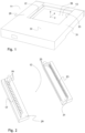
- the in figure 1 Illustrated device 11 for detecting, counting and classifying objects that pass a surveillance area 39, the shape of a frame light curtain with two parallel opposing legs, the transmitter block 29 and the receiver block 31.
- the transmitter block 29 there is a transmitter unit 17 and in the receiver block 31 a receiving unit 23 . Radiation emitted by the transmitting unit 17 is detected by the receiving unit 23 .
- the transmitter and receiver blocks 29, 31 are connected to a control unit 33.
- the control unit 33 has a microprocessor and at least one memory in which a program for controlling the transmitter and receiver blocks 29, 31 and for evaluation is stored.
- the monitoring area 39 formed by a substantially homogeneous touch panel 13 is located at a distance from the transmitter and receiver blocks 29, 31.
- the transmitter block 29 and the receiver block 31 are parallel to one another and in the same position in the direction of the x-axis Plane (same position in z-axis direction) aligned.
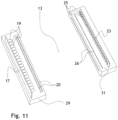
- FIG 2 shows a possible internal structure of a transmitter block 29 with the transmitter unit 17, which is equipped with a plurality of transmitter elements 19 (usually light-emitting diodes), and a receiver block 31 with the receiver unit 23, which is equipped with a plurality of radiation-sensitive receiver elements 25 (usually photodiodes).
- Transmitter and receiver block 29, 31 are each equipped with two screens 20, 26 (see embodiment according to figure 11 ) with slot length 1 (see figure 3 ) which cut the radiation emitted at a wide angle by the transmitter elements 19, so that the homogeneous, flat touch panel 13 with the height h (see figure 3 ) trains.
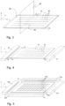
- FIG 3 shows the monitoring area 39, which is formed by a touch panel 13 generated by the transmitter block 29 and receiver block 31.
- the touch field extends in the x-direction over the length l, which is defined by the length of the slit of the apertures 20 or 29 in the transmitter 29 or receiver block 31 minus twice the distance d l (see figure 4 ) is specified. Its height h is determined by the slit width of the screens 20, 26 (see figure 11 ), the width b is defined by the distance of the receiver block from the transmitter block minus twice the distance db (see figure 4 ).
- the individual arrows 41 in the touch panel 13 symbolize the direction of the radiation emitted by the transmitter block 29 . In fact, each transmission element 19 radiates at a wide angle.
- FIG. 4 shows a first embodiment A of a sensor arrangement consisting of a transmitter block 29 and a receiver block 31, which together form the monitoring area 39 consisting of the touch panel 13.
- the individual arrows 41 in the touch panel 13 symbolize the radiation emitted by the transmitter block and received by the receiver block.
- figure 5 shows a second embodiment B of a sensor arrangement, which has a monitoring area 39, which consists of two touch fields 13 and 14, which lie in a common plane.
- the transmitter-receiver block pairs 29a/31a and 29b/31b are arranged perpendicular to one another.
- the individual arrows 41a and 41b drawn in the two touch fields symbolize the radiation emitted by the transmitter blocks 29a and 29b, which is received by the assigned receiver blocks 31a and 31b.
- FIG. 6 shows a third embodiment C of a detection device with a monitoring area 39 consisting of two plane-parallel touch fields 13 and 15 arranged at a distance d from one another, in which the transmitter and receiver blocks are each arranged one above the other.
- a touch panel arrangement is particularly suitable for detecting the projected area of objects independently of the speed.
- the individual arrows 41a and 41c drawn in the two touch fields 13 and 15 symbolize the radiation emitted by the transmitter blocks 29a and 29c, which is received by the associated receiver blocks 31a and 31c.
- the fourth embodiment D shown in 7 Is a combination of the embodiments B and C according to the figures 5 and 6 .
- the monitoring area 39 has a total of three touch panels 13 , 14 and 15 .
- the touch fields 13 and 14 lie in a common plane, the touch field 15 at a distance d plane-parallel to the touch fields 13 and 14.
- the individual arrows 41a, 41b and 41c drawn in the touch fields symbolize the radiation emitted by the transmitter blocks 29a, 29b and 29c , which is received by the associated receiver blocks 31a, 31b and 31c.
- the device according to the invention works as follows: The radiation generated in the transmitter block 29 impinges in the receiver block 31 on the receiving elements 25, each of which generates an analogue signal proportional to the amount of radiation impinging. The signal from all receiving elements 25 is summed up and fed to an analog/digital converter in the control unit. There the analog received signal is digitized.
- the control unit determines the amount of radiation m i per time unit d e (e.g. 30 ⁇ s) at time t i , which was transmitted by the transmitting unit and received by the receiving unit ( 8 ).
- the control unit stores the value in an internal memory as a reference amount of radiation m ref .
- the reference amount of radiation m ref corresponds to the state when there is no object in the touch field. If an object now enters the touch field, then this is partially interrupted in the area in which the object is located and the amount of radiation m received by the receiving unit at time t i ; is thus less than m ref . If the length l of the touch field in direction x is known, the extent s i of the object at time t i can be determined using the ratio of m i to m ref .
- the control unit determines the point in time t s at which the object penetrates the sensing field: The object is considered to have entered the sensing field at point in time t s if the extent s determined at this point in time is one of s min derived extent S has exceeded min_in for the first time.
- the control unit determines the point in time t e at which the object has left the scanning field : The object is deemed to have left the scanning field at point in time te if the extent s e determined at this point in time is one of s min derived extension s min_out and optionally if the extension S min _ in was not exceeded again during the predetermined gap suppression time d g .
- the maximum extension s max of the object corresponds to the maximum value s i in the period t until te.
- the duration ⁇ t during which the object at least partially covers the touch field is the difference t e -t s .
- the integrated extension a of the object can be determined in the units of seconds x meters.
- the area in the unit of measurement m 2 can be calculated via the integrated extent a of the object in the unit of measurement seconds x meters, since the unit of measurement seconds converts to the unit of measurement meters based on the speed can be converted.
- the speed can either be measured or specified by the user.
- the expansion can be calculated from the given distance d between the two touch fields in direction z and the difference between the two times when the object enters the two touch fields of the object in direction z.
- the area can be calculated in units of m 2 without specifying the speed.
- a classification and thus an assignment to a counting channel can be carried out on the basis of one or more of the criteria of maximum extent s max , dwell time ⁇ t, integrated extent a or area and/or shape of the object.
- extension s is recorded in the period t s to t e , then this can be used for further analysis purposes in the light curtain or in an external unit, eg to optimize the object classification.
- FIG 11 shows how figure 2 schematically shows a possible internal structure of a transmitter block 29 and a receiver block 31.
- Transmitter and receiver blocks 29, 31 are each equipped with two screens 20, 26, which cut the radiation emitted at a wide angle by the transmitter elements, so that the homogeneous, flat touch panel 13 is formed.
- the invention can also serve as a robust and cost-effective replacement for a camera system that is used, for example, for object recognition or object classification.
- control unit can use configurable oversampling to suppress any noise:
- the device averages the amount of radiation mt determined per unit of time t e over a specified period of time. As a result, the device works more slowly and the time resolution is reduced, but the signal quality is improved.
- the embodiment described above is not to be considered as limiting.
- the present invention is not limited to a fork assembly.
- the transmitter and receiver blocks can be separate from each other, i.e. they do not have to be connected to each other via a connecting bar.
- the communication between the control unit and the transmitter and receiver blocks can take place via a cable or via radio.
- any form of radiation can be used in addition to light as the measuring radiation.
- a resolution of less than 0.3mm can be achieved.
- the invention relates to a method and a device for detecting and measuring objects when they pass a monitoring area 39 defined by one or more touch fields 13.
- a touch field is generated by a transmitter block 29 and a receiver block 31 arranged opposite.
- a transmitter block contains a plurality of transmitter elements 19 which emit radiation.
- a receiver block contains a plurality of receiving elements 25 which measure radiation.
- a touch panel is a substantially homogeneous plane of radiation. The radiation from a transmitting element impinges on a plurality of receiving elements, and a receiving element receives radiation from a plurality of transmitting elements. The radiation measured by the receiving elements is combined into one signal in the receiver block. The so achievable resolution is much finer than through the local arrangement of the Transmission or reception elements predetermined grid.
- the dwell time of an object in the touch field a large number of individual measurements are carried out and the shading of the receiving elements is determined by comparing the signal strengths with a covered and uncovered touch field and the projected extent of the object is calculated from this.
- the dwell time of the object in the touch field, the maximum projected extent, the integrated projected extent and the projected shape of the object can be determined by stringing together the individual measurements carried out one after the other.
- the data collected about an object can be used to classify it, count it and visualize its shape.
Description
Die Erfindung betrifft ein Verfahren und eine Vorrichtung zum Erfassen und Vermessen von Objekten beim Passieren eines Überwachungsbereiches.The invention relates to a method and a device for detecting and measuring objects as they pass through a surveillance area.
Lichtschranken finden in der Technik vielfältig Verwendung. Eine typische Anwendung ist die Detektierung von beweglichen Gegenständen außerhalb einer Führung. Hierzu werden in der Regel Rahmenlichtschranken verwendet, bei denen ein oder eine Mehrzahl von Lichtsendern und zugeordneten Lichtempfängern in einander gegenüberliegenden Schenkeln eines Trägers der Lichtschranke angeordnet sind, um einen aus einzelnen Lichtwegen aufgebauten Überwachungsbereich zu bilden, in der Folge als Tastfeld bezeichnet. Für gewöhnlich sind diese Schenkel mittels eines Verbindungsschenkels und einer Traverse, welche rechtwinklig von den Schenkeln abstehen, zu einem Rahmen verbunden.Light barriers are used in many different ways in technology. A typical application is the detection of moving objects outside of a guide. Frame light barriers are usually used for this purpose, in which one or a plurality of light transmitters and associated light receivers are arranged in opposite legs of a carrier of the light barrier in order to form a monitoring area made up of individual light paths, hereinafter referred to as a touch panel. Usually, these legs are connected to form a frame by means of a connecting leg and a traverse, which protrude at right angles from the legs.
Befindet sich ein Gegenstand im Tastfeld oder bewegt sich ein Gegenstand durch das Tastfeld hindurch und unterbricht mindestens einen Lichtweg, ist die vom Lichtempfänger erfassbare Lichtmenge betragsmäßig verändert. Die Veränderung in der Lichtmenge ist mit einer dafür vorgesehenen und eingerichteten Elektronik messbar und mit einem justierbaren Schwellenwert vergleichbar. Eine Abweichung zwischen dem gemessenen Wert der Lichtmenge und dem Schwellenwert ist in ein Schaltsignal zur Anzeige einer Gegenwart des Gegenstandes im Tastfeld umsetzbar.If an object is located in the touch field or if an object moves through the touch field and interrupts at least one light path, the amount of light that can be detected by the light receiver changes. The change in the amount of light can be measured with electronics provided and set up for this purpose and can be compared with an adjustable threshold value. A deviation between the measured value of the amount of light and the threshold value can be converted into a switching signal to indicate the presence of the object in the touch panel.
In der
Lichtgitter umfassen eine Mehrzahl von Sendeelementen und zugeordneten Empfangselementen, so dass jeweils ein Paar aus einem Sendeelement und einem Empfangselement eine Lichtschranke bildet, die erkennt, ob der zwischen dem Sendeelement und dem Empfangselement aufgespannte Lichtstrahl von einem Objekt unterbrochen ist oder nicht. Lichtgitter weisen kein homogenes Tastfeld auf, sondern besitzen, wie die Bezeichnung «Gitter» bereits suggeriert, einzelne gebündelte Lichtstrahlen. Die Sendeelemente und Empfangselemente sind jeweils in einer Sendeeinheit und einer Empfangseinheit zusammengefasst, die einander gegenüber montiert werden. Eine Kontrolleinheit steuert Sendeeinheit und Empfangseinheit. Sie wertet die von der Sendeeinheit ausgesendete und von der Empfangseinheit empfangene Lichtmenge aus und erfasst anhand dieser Information Objekte, die das Tastfeld passieren. Die Kontrolleinheit verfügt üblicherweise über einen oder mehrere Ausgänge sowie evtl. über Eingänge, um mit anderen Geräten Daten auszutauschen. Über einen Ausgang teilt das Lichtgitter beispielsweise einer übergeordneten Einheit mit, dass ein Objekt erfasst wurde. Über die evtl. vorhandenen Eingänge kann eine untere Grössengrenze festgelegt werden, ab der Objekte erfasst werden sollen. Manche auf dem Markt verfügbaren Geräte bieten zudem die Möglichkeit, auch eine Grenze für die minimale Zeit festzulegen, die ein Objekt das Tastfeld bedecken muss, damit es erfasst werden soll. Die meisten Geräte sind mit einer Funktion zum Minimieren des Einflusses von Umgebungslicht ausgestattet.Light grids include a plurality of transmitting elements and associated receiving elements, so that a pair of a transmitting element and a Receiving element forms a light barrier that detects whether the spanned between the transmitting element and the receiving element light beam is interrupted by an object or not. Light grids do not have a homogeneous touch field, but rather, as the term “grid” already suggests, have individual bundled light beams. The transmission elements and reception elements are each combined in a transmission unit and a reception unit, which are mounted opposite one another. A control unit controls the transmitting unit and receiving unit. It evaluates the amount of light emitted by the transmitter unit and received by the receiver unit and uses this information to detect objects that pass the touch panel. The control unit usually has one or more outputs and possibly inputs to exchange data with other devices. For example, the light grid uses an output to inform a higher-level unit that an object has been detected. A lower size limit from which objects are to be recorded can be defined via the possibly existing inputs. Some devices available on the market also offer the possibility of also setting a limit for the minimum time that an object must cover the sensing field in order for it to be detected. Most devices are equipped with a feature to minimize the influence of ambient light.
Ein herkömmliches Anwendungsfeld für Lichtgitter ist die Sicherheitstechnik. Die parallelen Lichtstrahlen dienen dabei als eine Art virtuelle Wand, mit der eine potentielle Gefahrenquelle abgesichert werden kann. Dabei kann ein Alarm ausgelöst oder eine Aktion veranlasst werden, wenn ein oder mehrere Lichtstrahlen unterbrochen werden.A conventional field of application for light grids is safety technology. The parallel light beams serve as a kind of virtual wall with which a potential source of danger can be secured. An alarm can be triggered or an action initiated if one or more light beams are interrupted.
In der Automatisierungstechnik werden Lichtgitter eingesetzt, um die Ausdehnung von Objekten anhand der Anzahl unterbrochener Strahlen zu messen. Dabei ist die Genauigkeit der Messung durch den Abstand der Lichtstrahlen bestimmt.In automation technology, light grids are used to measure the extent of objects based on the number of interrupted beams. The accuracy of the measurement is determined by the distance between the light beams.
In der
Wie in der
Die
Die
Lichtgitter können auch verwendet werden, um Teile zu zählen, die beispielsweise von einer Fördervorrichtung fallen. Das Lichtgitter wird dann so angeordnet, dass seine Überwachungsebene ein üblicherweise horizontales Fenster überdeckt, durch welches die Teile hindurchfallen. Hier eignet sich ein Lichtgitter vor allem dann, wenn die Teile keine genau vorhersagbare Bewegungsbahn verfolgen und deshalb nicht immer an der gleichen Stelle, sondern nur innerhalb eines gewissen Bereichs vermessen oder gezählt werden können. Ein Lichtgitter kann aber nur Teile erfassen, die eine gewisse Mindestgröße aufweisen. Dies liegt daran, dass ein Lichtgitter ohne zusätzliche Maßnahmen nur ein Auflösungsvermögen besitzt, welches dem Strahlabstand des Lichtgitters entspricht.Light grids can also be used to count parts falling off a conveyor, for example. The light grid is then arranged in such a way that its monitoring plane covers a usually horizontal window through which the parts fall. A light grid is particularly suitable here if the parts do not follow a precisely predictable movement path and can therefore not always be measured or counted at the same point, but only within a certain range. However, a light grid can only detect parts that have a certain minimum size. This is because, without additional measures, a light grid only has a resolution that corresponds to the beam separation of the light grid.
Bekannte Lichtgitter haben den Nachteil, dass sie Objekte nicht oder nur in der durch den Strahlabstand vorgegebenen Auflösung klassifizieren können. Unter Klassifizieren ist im Rahmen der vorliegenden Erfindung gemeint, dass ein Objekt anhand vorgegebener Merkmale einer bestimmten Klasse zugeordnet werden kann, mit dem Zweck, Objekte differenzieren zu können. Beispielsweise können konventionelle Lichtgitter beim Zählen von gleichen Metallfedern nicht zuverlässig feststellen, wenn zwei Federn ineinander verwickelt sind und das Tastfeld daher ohne Abstand untereinander passieren. Die ineinander verwickelten Federn werden deshalb nur als eine Feder erfasst. Konventionelle Lichtgitter können auch nicht Fehlteile (z.B. bei Plastikgussteilen vorhandene Stege zum Austrennen der Teile oder Schrauben mit fehlendem Kopf) zuverlässig aussortieren. Auch können konventionelle Lichtgitter mehrere verschieden grosse Schrauben, die zwar zeitlich nacheinander aber untereinander vermischt den Überwachungsbereich passieren, nicht nach Grössenklassen geordnet getrennt zählen, da sie deren Grösse nicht ausreichend genau messen können.Known light grids have the disadvantage that they cannot classify objects or can only classify them with the resolution specified by the beam spacing. In the context of the present invention, classification means that an object can be assigned to a specific class on the basis of predetermined characteristics, with the purpose of being able to differentiate objects. For example, when counting the same metal springs, conventional light grids cannot reliably determine when two springs are entangled in one another and the touch panel is therefore without a gap happen to each other. The entangled springs are therefore only detected as one spring. Conventional light grids are also unable to reliably sort out missing parts (e.g. webs for cutting out the parts in the case of plastic cast parts or screws with a missing head). Also, conventional light grids cannot count several screws of different sizes, which pass through the monitoring area one after the other but mixed up with each other, sorted according to size classes, since they cannot measure their size with sufficient accuracy.
Bekannte Lichtgitter können zudem Objekte mit dünnen oder (teil-) durchsichtigen Bereichen, z.B. Milchglas, oder Objekte, die während dem Passieren des Tastfelds rotieren, nicht zuverlässig als ein einzelnes Objekt erkennen.In addition, known light grids cannot reliably identify objects with thin or (partially) transparent areas, e.g. frosted glass, or objects that rotate while passing the touch field as a single object.
Lichtschranken mit einem homogenen Lichtfeld, das von einer Mehrzahl Empfangselemente detektiert wird, sind aus den Dokumenten
Ausgehend von dem eingangs beschriebenen Stand der Technik ist deshalb ein Ziel der vorliegenden Erfindung, ein Verfahren und eine Vorrichtung zur Verfügung zu stellen, mit deren Hilfe Objekte beliebiger Formen und Materialien, z.B. auch solche mit dünnen oder (teil-) durchsichtigen Bereichen, in einer Auflösung, die nicht durch den Abstand der Sendeelemente untereinander und dem Abstand der Empfangselemente untereinander limitiert ist, vermessen und damit zuverlässig erfasst, gezählt und klassifiziert werden können. Ein zweites Ziel ist, dass Objekte, die während dem Passieren des Überwachungsbereichs rotieren, zuverlässig erfasst und gezählt werden können. Ein drittes Ziel ist, dass Objekte zuverlässig nach ihrer maximalen Ausdehnung und/oder ihrer Verweilzeit klassifiziert werden können. Ein viertes Ziel ist, dass Objekte zuverlässig nach ihrer Fläche klassifiziert werden können. Ein weiteres Ziel ist, dass Objekte zusätzlich nach Ihrer Form, d.h. nach Ihrer zeitpunkts- bzw. ortsabhängigen Ausdehnung klassifiziert werden können. Ein weiteres Ziel ist, dass die Empfindlichkeit der Vorrichtung gegenüber Störungen auf Kosten einer geringeren Arbeitsgeschwindigkeit verbessert werden kann und vice versa. Auch ist es wünschenswert, dass die Form der erfassten Objekte visualisiert werden kann.Based on the prior art described above is therefore an object of the present invention to provide a method and a device available, with the help of objects of any shape and material, such as those with thin or (partially) transparent areas, in a Resolution, which is not limited by the distance between the transmitting elements and the distance between the receiving elements, can be measured and thus reliably recorded, counted and classified. A second goal is that objects rotating while passing through the surveillance area can be reliably detected and counted. A third goal is that objects can be reliably classified according to their maximum extent and/or their dwell time. A fourth goal is that objects can be reliably classified according to their area. Another goal is that objects can also be classified according to their shape, ie according to their time- or location-dependent expansion. Another aim is that the sensitivity of the device to disturbances can be improved at the expense of a lower operating speed and vice versa. Also, it is desirable that the shape of the detected objects can be visualized.
Ein Überwachungsbereich besteht aus einem oder mehreren Tastfeldern. Ein Tastfeld wird durch einen Senderblock und einem zu diesem parallel und in einer Ebene angeordneten Empfängerblock erzeugt. Der Senderblock emittiert Strahlung, die vom Empfängerblock empfangen und gemessen wird.A monitoring area consists of one or more touch fields. A touch panel is generated by a transmitter block and a receiver block arranged parallel to it and in one plane. The transmitter block emits radiation that is received and measured by the receiver block.
Unter «Vermessen» wird im Rahmen der vorliegenden Erfindung verstanden, dass einer oder mehrere der folgenden Werte eines Objekts, das den Überwachungsbereich der Vermessungsvorrichtung passiert, ermittelt werden: Die zeitpunktabhängige Ausdehnung des Objekts, die Dauer, während der das Objekt ein Tastfeld bedeckt, aufintegrierte Ausdehnung des Objekts und die Form des Objekts.In the context of the present invention, "measurement" is understood to mean that one or more of the following values of an object that passes the monitoring area of the measurement device are determined: the time-dependent extent of the object, the duration during which the object covers a touch field, integrated extent of the object and the shape of the object.
Mit «Ausdehnung» bzw. «Grösse» des Objekts ist immer die Projektion des Objekts auf den Empfänger, bzw. der Schattenwurf der von der Sendeeinheit emittierten Strahlung auf die Empfangseinheit gemeint.The "expansion" or "size" of the object always means the projection of the object onto the receiver, or the shadow cast by the radiation emitted by the transmitter unit on the receiver unit.
«Klassifizieren» bedeutet, dass ein Objekt anhand vorgegebener Merkmale einer bestimmten Klasse zugeordnet werden kann, mit dem Zweck, Objekte differenzieren zu können."Classification" means that an object can be assigned to a specific class based on given characteristics, with the purpose of being able to differentiate objects.
Die Minimalausdehnung smin ist ein anwendungsspezifischer unterer Schwellenwert, der vorgegeben wird. Er entspricht der Ausdehnung des kleinsten Objekts, das erfasst werden soll.The minimum expansion s min is an application-specific lower threshold value that is specified. It corresponds to the extent of the smallest object that is to be detected.
Die Ausdehnung smin_in ist ein vorrichtungs- und anwendungsspezifischer Schwellenwert, der tiefer als die Minimalausdehnung smin angesetzt wird. Er repräsentiert die intern verwendete Schwelle für die Ausdehnung, ab der die Vorrichtung ein Objekt als "ist ins Tastfeld eingetreten" detektiert.The extent s min_in is a device and application specific threshold set lower than the minimum extent s min . It represents the internally used threshold for the extent from which the device detects an object as "has entered the scanning field".
Die Ausdehnung smin_out ist ein vorrichtungs- und anwendungsspezifischer Schwellenwert, der tiefer als die Ausdehnung smin_in angesetzt wird. Er repräsentiert die intern verwendete Schwelle für die Ausdehnung, ab der die Vorrichtung ein Objekt als "hat das Tastfeld verlassen" detektiert (Ausnahme: siehe Erklärungen zum Begriff Lückenunterdrückungszeit).
- ts ist der Zeitpunkt, wenn die Vorrichtung ein Objekt als "ist ins Tastfeld eingetreten" detektiert.
- te ist der Zeitpunkt, wenn die Vorrichtung ein Objekt als "hat das Tastfeld verlassen" detektiert.
- t s is the time when the device detects an object as "entered the touch field".
- t e is the time when the device detects an object as "has left the field of view".
Die Verweilzeit Δt ist die Differenz zwischen te und ts, d.h. die von der Vorrichtung ermittelte Zeit, während der das Objekt das Tastfeld bedeckt hat.The dwell time Δt is the difference between t e and t s , ie the time determined by the device during which the object covered the touch field.
Die Lückenunterdrückungszeit gibt vor, wie lange die Vorrichtung ein Objekt noch nicht als "hat das Tastfeld verlassen" detektieren soll, obwohl die gemessene Ausdehnung bereits unter der Schwelle smin_out gefallen ist. Steigt in diesem Fall die gemessene Ausdehnung innerhalb der Lückenunterdrückungszeit wieder über die Schwelle smin_in, dann wird das vorherige Unterschreiten der Schwelle smin_out nicht berücksichtigt. Eine Lückenunterdrückungszeit > 0 wird gesetzt, wenn das zu erfassende Objekt einen oder mehrere dünne oder (teil-) durchsichtige Bereiche aufweist oder wenn es beim Passieren des Tastfelds rotiert, d.h. durch die Rotation das Tastfeld betritt, verlässt und danach wieder betritt.The gap suppression time specifies how long the device should not yet detect an object as "has left the scanning field", although the measured extent has already fallen below the threshold s min_out . If, in this case, the measured expansion rises above the threshold s min_in again within the gap suppression time, then the fact that the threshold s min_out was previously fallen below is not taken into account. A gap suppression time > 0 is set if the object to be detected has one or more thin or (partially) transparent areas or if it rotates when passing the touch field, ie enters the touch field as a result of the rotation, leaves it and then re-enters it.
Die Ausdehnung smax entspricht dem maximalen Wert si der im Zeitraum ts bis te liegt.The extent s max corresponds to the maximum value s i in the period t s to t e .
Erfindungsgemäss werden die vorerwähnten Ziele durch die Merkmale der Ansprüche 1 und 6 realisiert. Vorteilhafte Weiterbildungen sind in den Unteransprüchen definiert. Die Erfindung betrifft ein Verfahren und eine Vorrichtung zum Erfassen und Vermessen von Objekten beim Passieren eines Überwachungsbereichs.According to the invention, the above objects are realized by the features of claims 1 and 6. Advantageous developments are defined in the dependent claims. The invention relates to a method and a device for detecting and measuring objects as they pass through a surveillance area.
Die vorliegende Erfindung bezieht sich nicht auf eine wie eingangs in den zitierten Patenten beschriebene Sensorvorrichtung in Gestalt eines aus einzelnen, von Sendeelementen emittierten, gebündelten Strahlengängen aufgebauten Lichtgitters oder solche Sensorvorrichtungen, die erkennen, welche Empfangselemente Strahlung empfangen und welche nicht, sondern auf eine neuartige Vorrichtung, insbesondere Lichtvorhang, mit einem oder mehreren im Wesentlichen homogenen und flächigen Tastfeldern, wobei eine Empfangseinheit die empfangene Strahlungsmenge nur gesamthaft misst und somit lediglich ein einziges Signal zur Verfügung stellt. Die Anzahl und der Abstand der benachbarten Sende- und Empfangselemente voneinander bestimmt nicht mehr direkt die Auflösung, tatsächlich können beispielsweise mit im Abstand von 6mm angeordneten Sende- und Empfangselementen Auflösungen unter 0.5mm erreicht werden.The present invention does not relate to a sensor device as initially described in the cited patents in the form of a light grid composed of individual bundled beam paths emitted by transmitting elements or such sensor devices that recognize which receiving elements receive radiation and which do not, but to a novel device , in particular Light curtain, with one or more essentially homogeneous and flat touch panels, with a receiving unit measuring the received amount of radiation only as a whole and thus providing only a single signal. The number and the distance between the adjacent transmitting and receiving elements no longer directly determine the resolution; in fact, for example, with transmitting and receiving elements arranged at a distance of 6mm, resolutions of less than 0.5mm can be achieved.
Gemäss dem Verfahren bedeckt ein an einem ersten Rand des Überwachungsbereichs angeordneter erster Senderblock zur Aussendung von vorzugsweise elektromagnetischer Strahlung den Überwachungsbereich mit einer flächigen Strahlungsebene. Der Senderblock beinhaltet eine Sendeeinheit, die mit n Sendeelementen bestückt ist. Die von jedem Sendelement emittierte Strahlung ist nicht gebündelt, sondern wird breitwinklig ausgesendet. Breitwinklig heisst, dass ein Sendelemente einen grossen Prozentsatz der von ihm erzeugten Strahlung kegelförmig aussendet, beispielsweise 90% der Strahlungsmenge in einem Kegel mit beispielsweise einem Öffnungswinkel von +-5 Grad, +-10 Grad, oder +-15 Grad um die Hauptstrahlungsrichtung. Die von den n Sendelementen jeweils breitwinklig emittierte Strahlung trifft anschliessend auf zwei im Senderblock integrierte, hintereinander angeordnete Blenden mit einer typischen Schlitzbreite von 1mm, wodurch die austretende Strahlung eine Strahlungsebene bildet. Die an einem beliebigen Punkt in der Strahlungsebene gemessene, vom Senderblock emittierte Strahlung stammt also nicht nur von einem Sendelement, sondern von bis zu n Sendelementen, wobei n bei einer Tastfeldlänge von 100mm vorzugsweise grössser als 30 und besonders bevorzugt grösser als 40 ist. Bei längeren Tastfeldlängen kann die Zahl der Sendeelemente entsprechend grösser sein. Ein an einem zweiten Rand des Überwachungsbereichs angeordneter erster Empfängerblock, der eine Empfangseinheit mit m Empfangselementen beinhaltet und sich im Wesentlichen parallel zum Senderblock erstreckt und diesem gegenüberliegt, erfasst die vom Senderblock ausgesandte Strahlung. Im Empfängerblock sind ebenfalls zwei hintereinander angeordnete Blenden mit einer typischen Schlitzbreite von 1mm integriert, die einen Teil der vom Senderblock emittierten Strahlung passieren lassen. Ein Empfangselement empfängt somit Strahlung von bis zu n Sendelementen. Die Zahl m der Empfangselemente ist bei einer Tastfeldlänge von 100mm vorzugsweise grösser als 20 und besonders bevorzugt grösser als 30. Bei längeren Tastfeldlängen kann die Zahl der Empfangselemente entsprechend grösser sein.According to the method, a first transmitter block arranged at a first edge of the monitored area for emitting preferably electromagnetic radiation covers the monitored area with a flat radiation plane. The transmitter block contains a transmitter unit that is equipped with n transmitter elements. The radiation emitted by each transmission element is not bundled, but is sent out at a wide angle. Wide-angle means that a transmitting element emits a large percentage of the radiation it generates in a cone shape, for example 90% of the amount of radiation in a cone with, for example, an opening angle of +-5 degrees, +-10 degrees, or +-15 degrees around the main radiation direction. The wide-angle radiation emitted by the n transmitter elements then impinges on two screens integrated in the transmitter block and arranged one behind the other with a typical slit width of 1 mm, as a result of which the emitted radiation forms a radiation plane. The radiation measured at any point in the radiation plane and emitted by the transmitter block does not come from just one transmitter element, but from up to n transmitter elements, with n preferably being greater than 30 and particularly preferably greater than 40 for a scanning field length of 100 mm. In the case of longer touch field lengths, the number of transmission elements can be correspondingly greater. A first receiver block, which is arranged at a second edge of the monitoring area and contains a receiver unit with m receiver elements and extends essentially parallel to the transmitter block and faces it, detects the radiation emitted by the transmitter block. In the receiver block there are also two consecutively arranged screens with a typical slit width of 1mm, which allow part of the radiation emitted by the transmitter block to pass through. A receiving element thus receives radiation of up to n send items. In the case of a touch field length of 100 mm, the number m of receiving elements is preferably greater than 20 and particularly preferably greater than 30. In the case of longer touch field lengths, the number of receiving elements can be correspondingly greater.
Vorzugsweise bildet ein Ausschnitt der Strahlungsebene das Tastfeld, in dem Objekte erfasst werden. Die Länge der Schlitze der Blenden in Sender- und Empfängerblock abzüglich zweimal einer festgelegten Distanz dl bestimmt die Länge des Tastfelds. Seine Höhe ist durch die Schlitzbreite der Blenden definiert, die Breite durch den Abstand des Empfängerblocks vom Senderblock abzüglich zweimal einer festgelegten Distanz db. Das Tastfeld wird dabei mittig angeordnet, im Abstand dl vom Tastfeld enden also die Blendenschlitze und im Abstand db beginnt der Sender- bzw. der Empfängerblock. dl und db können bei einer Länge der Blendenschlitze von 100mm beispielsweise 5mm betragen. Bei einem Abstand zwischen Sender- und Empfängerblock von 150mm resultiert damit ein Tastfeld der Länge 140mm und Breite 90mm. Die Blendenschlitzbreite und damit die Tastfeldhöhe sollten vorzugsweise gering sein, da durch die Tastfeldhöhe direkt das Auflösungsvermögen des Lichtvorhangs bestimmt wird. Üblicherweise beträgt die Höhe des Tastfelds zwischen 0.1mm und 3mm, typischerweise ungefähr 1mm.A section of the radiation plane preferably forms the touch field in which objects are detected. The length of the slits of the screens in the transmitter and receiver block minus twice a fixed distance dl determines the length of the touch panel. Its height is defined by the slit width of the apertures, the width by the distance between the receiver block and the transmitter block minus twice a fixed distance d b . The touch field is arranged in the middle, so the aperture slits end at a distance d l from the touch field and the transmitter or receiver block begins at a distance d b . dl and db can be 5mm, for example, with a length of the aperture slits of 100mm. With a distance of 150mm between the transmitter and receiver block, this results in a touch panel with a length of 140mm and a width of 90mm. The aperture slit width and thus the height of the touch panel should preferably be small, since the resolution of the light curtain is directly determined by the height of the touch panel. Usually the height of the touch panel is between 0.1mm and 3mm, typically around 1mm.
Das Tastfeld muss möglichst homogen sein. Ein homogenes Tastfeld ist dadurch charakterisiert, dass die durch eine Kugel, die sich an beliebiger Position aber gleicher Höhe im Tastfeld befindet, verursachte Verminderung der vom Senderblock emittierten und vom Empfängerblock gemessenen Strahlung im Wesentlichen konstant ist. Ein im Wesentlichen homogenes Tastfeld wird durch mehrere Massnahmen erreicht: Durch geschickte Auswahl, Anordnung und Ausrichtung der Sende- und Empfangselemente und durch unterschiedliche Strahlungsstärken der Sendeelemente. In der Praxis gibt es jedoch Abweichungen vom Idealfall, weil beispielsweise die verwendeten Leuchtdioden Fertigungstoleranzen aufweisen, weil Ungenauigkeiten in der Mechanik und in der Montage der Sende- und Empfangseinheit auftreten und weil vorhandene Umgebungsstrahlung Einfluss nehmen kann. Eine Abweichung von bis zu ± 30%, vorzugsweise von bis zu ± 20% und besonders bevorzugt ± 10% von der über das ganze Tastfeld gemittelten Strahlungsintensität soll im Rahmen der vorliegenden Erfindung immer noch als hinreichend homogen gelten. Eine vorhandene Inhomogenität des Tastfelds verursacht eine entsprechende Streuung der Messungen, die tolerierbare Abweichung vom Idealfall ist abhängig von der Applikation.The touch field must be as homogeneous as possible. A homogeneous touch field is characterized in that the reduction in the radiation emitted by the transmitter block and measured by the receiver block caused by a sphere located at any position but at the same height in the touch field is essentially constant. A substantially homogeneous touch field is achieved by several measures: by skilful selection, arrangement and alignment of the transmitting and receiving elements and by different radiation intensities of the transmitting elements. In practice, however, there are deviations from the ideal case, for example because the light-emitting diodes used have manufacturing tolerances, because inaccuracies occur in the mechanics and in the assembly of the transmitter and receiver unit, and because existing ambient radiation can have an effect. A deviation of up to ±30%, preferably up to ±20% and particularly preferably ±10% from that averaged over the entire touch panel In the context of the present invention, radiation intensity should still be considered to be sufficiently homogeneous. An existing inhomogeneity of the touch panel causes a corresponding scattering of the measurements, the tolerable deviation from the ideal case depends on the application.
Die Zahl der Sendeelemente und Empfangselemente muss keineswegs übereinstimmen. Alle Sendelemente werden vorzugsweise synchron betrieben, die Empfangseinheit fasst die Signale der Empfangselemente für die Auswertung zu einem einzigen Signal zusammen. Passiert ein Objekt das Tastfeld, dann wird das Tastfeld partiell unterbrochen und als Folge empfangen bis zu m Empfangselemente weniger Strahlung von den Sendeelementen der Sendeeinheit. Das von der Empfangseinheit gelieferte Signal ist schwächer.The number of transmitting elements and receiving elements does not have to match. All transmitting elements are preferably operated synchronously, and the receiving unit combines the signals from the receiving elements into a single signal for evaluation. If an object passes the touch field, the touch field is partially interrupted and as a result up to m receiving elements receive less radiation from the transmitting elements of the transmitting unit. The signal supplied by the receiving unit is weaker.
Eine Kontrolleinheit resp. ein in der Kontrolleinheit abgespeichertes Programm (Software) registriert anhand der beim Passieren des Überwachungsbereichs bewirkten Veränderung der vom Empfängerblock registrierten Intensitäten der Strahlung ein Objekt. Die Kontrolleinheit kann eine oder mehrere Rechner umfassen, die lokal getrennt und über eine Datenverbindung miteinander verbunden sein können. Entsprechend kann auch das Erfassungs- und Auswerteprogramm auf mehrere Rechner verteilt sein.A control unit a program (software) stored in the control unit registers an object based on the change in the intensities of the radiation registered by the receiver block caused when passing the monitored area. The control unit can include one or more computers that can be locally separated and connected to one another via a data connection. Correspondingly, the acquisition and evaluation program can also be distributed over several computers.
Das Verfahren ist im Weiteren dadurch charakterisiert, dass eine Kontrolleinheit, die mit dem ersten Sender- und dem ersten Empfängerblock zwecks Steuerung derselben in Verbindung steht, aus der durch ein Objekt beim Passieren des Tastfelds bewirkten Veränderung der von den Empfangselementen des Empfängerblocks empfangenen Strahlung die auf den Empfängerblock projizierte Ausdehnung des Objekts zu verschiedenen Zeitpunkten, währenddem das Objekt das Tastfeld passiert, ermittelt. Aus der projizierten Ausdehnung kann nach dem Passieren des Objekts eine oder mehrere der nachfolgend erwähnten Grössen berechnet werden: Die Verweilzeit des Objekts, und/oder die maximale projizierte Ausdehnung und/oder die aufintegrierte projizierte Ausdehnung des Objekts. Die erfassten zu einem Objekt gehörenden zeitpunktabhängigen Ausdehnungen können zu einer aufintegrierten Ausdehnung zusammengesetzt werden. Die Berechnung der aufintegrierten Ausdehnung kann dabei bereits in der Kontrolleinheit, die einen Rechner umfasst und in der Vorrichtung integriert ist, oder in einem zweiten Rechner erfolgen, der über eine Datenverbindung mit dem Rechner der Kontrolleinheit in Verbindung steht. Dieses Verfahren hat zwei grosse Vorteile: Die Form eines das Tastfeld passierendes Objekt kann aufgezeichnet und visualisiert werden und es ist möglich, seine aufintegrierte Ausdehnung zu berechnen. Dies erlaubt es, Objekte unterschiedlicher Dimensionen und Formen auseinander zu halten und separat zu erfassen.The method is further characterized in that a control unit, which is connected to the first transmitter and the first receiver block for the purpose of controlling them, calculates the change in radiation received by the receiver elements of the receiver block from the change caused by an object passing the touch panel determines the extent of the object projected by the receiver block at different points in time while the object is passing the touch field. After the object has passed, one or more of the variables mentioned below can be calculated from the projected extent: the dwell time of the object, and/or the maximum projected extent and/or the integrated projected extent of the object. The detected time-dependent extents belonging to an object can be combined to form an integrated extent. The calculation of the integrated extent can already be done in the control unit, which includes a computer, and in the device is integrated, or take place in a second computer which is connected to the computer of the control unit via a data connection. This method has two major advantages: the shape of an object passing the touch field can be recorded and visualized and it is possible to calculate its integrated extent. This allows objects of different dimensions and shapes to be distinguished and recorded separately.
Während der Verweilzeit eines Objekts im Tastfeld kann eine Vielzahl von Messungen durchgeführt und die Signalstärke mit derjenigen bei freiem, d.h. nicht teilweise durch das Objekt bedecktem Tastfeld, verglichen werden. Vorzugsweise erfolgen die Messungen kontinuierlich und in möglichst kurzen Zeitabständen. Die Geschwindigkeit, mit der gemessen werden kann, ist primär durch die verwendete Hardware und die gewünschte Auflösung begrenzt. Üblicherweise dauert eine Messung zwischen 30 und 100 Mikrosekunden, Zur Auswertung kann über mehrere Messungen gemittelt werden, um die Signalqualität zu verbessern.A large number of measurements can be carried out while an object is in the scanning field and the signal strength can be compared with that when the scanning field is free, i.e. not partially covered by the object. The measurements preferably take place continuously and at the shortest possible time intervals. The speed at which measurements can be taken is primarily limited by the hardware used and the desired resolution. A measurement usually lasts between 30 and 100 microseconds. Several measurements can be averaged for evaluation in order to improve the signal quality.
Die erfasste maximale Ausdehnung und die Verweilzeit eines Objekts hängen beide stark von der Orientierung des Objekts beim Passieren des Tastfelds ab. Bewegen sich aber mehrere gleiche Objekte zeitlich hintereinander derart durch das Tastfeld, dass sich die zu vermessende Fläche jeweils in einer beliebigen Ebene senkrecht zum Tastfeld und parallel zum Sender- und Empfängerblock aber ansonsten beliebig orientiert durch das Tastfeld bewegt, dann ist die ermittelte aufintegrierte Ausdehnung aller Objekte übereinstimmend. Dies ist der Fall, weil die Anordnung die auf den Empfängerblock projizierte Ausdehnung eines Objekts vermisst, die immer parallel zum Sender- und Empfängerblock im Raum liegt.The detected maximum extent and the dwell time of an object are both highly dependent on the orientation of the object as it passes the touch pad. However, if several identical objects move through the touch field one after the other in such a way that the area to be measured moves through the touch field in any plane perpendicular to the touch field and parallel to the transmitter and receiver block but otherwise oriented in any way, then the determined integrated extension of all Objects matching. This is because the arrangement measures the extent of an object projected onto the receiver block, which is always parallel to the transmitter and receiver blocks in space.
Die Ermittlung der aufintegrierten Ausdehnung eines Objekts stellt daher für das Vornehmen einer Klassifizierung eine sehr viel zuverlässigere Bezugsgrösse dar als die gemessene maximale Ausdehnung und die Verweilzeit des Objekts im Tastfelds.The determination of the integrated extent of an object therefore represents a much more reliable reference value for carrying out a classification than the measured maximum extent and the dwell time of the object in the touch field.
Gleiche Objekte, die zu nahe aufeinanderfolgen, d.h. solche bei denen sich ihre Projektionen auf den Empfänger überlappen, können auseinandergehalten und als zwei Objekte erfasst werden.Identical objects that follow each other too closely, ie those whose projections onto the receiver overlap, can be distinguished and detected as two objects.
Wird zusätzlich die zeitpunkt- bzw. ortsabhängige Ausdehnung des Objekts analysiert, dann steht ein zusätzliches Kriterium zur Klassifizierung zur Verfügung, welches auch die Form eines Objekts berücksichtigt.If the time or location-dependent extension of the object is also analyzed, then an additional criterion is available for classification, which also takes the shape of an object into account.
Damit können in einem Arbeitsgang Objekte unterschiedlicher Dimensionen und Formen unterschieden werden. Entsprechend kann die Vorrichtung in Sortier- oder Zählprozessen eingesetzt werden. Beispielsweise können auf einem Förderband transportierte, unterschiedliche Objekte durch das eingesetzte Vermessungsverfahren zuverlässig auseinandergehalten werden.In this way, objects of different dimensions and shapes can be distinguished in one operation. Accordingly, the device can be used in sorting or counting processes. For example, different objects transported on a conveyor belt can be reliably distinguished by the measurement method used.
Gemäss einer bevorzugten Verfahrensvariante werden die Sendeelemente gepulst. Dies hat den Vorteil, dass Störeinflüsse durch Fremdstrahlung eliminiert werden können. In einer Ausführungsvariante werden die Sendeelemente pro Messung einmal gepulst. Die Pulsweite kann symmetrisch oder asymmetrisch verteilt sein, d.h. die Phase, in der die Sendelemente Strahlung aussenden, muss nicht zwingend gleich lang sein wie die Phase in der sie inaktiv sind. Für den Fall, dass eine einzelne Messung insgesamt beispielsweise 30 Mikrosekunden benötigt, könnte die Phase, in der Sendeelemente Strahlung aussenden, 10 Mikrosekunden und somit die Phase, in der sie inaktiv sind, 20 Mikrosekunden dauern.According to a preferred variant of the method, the transmission elements are pulsed. This has the advantage that interference from extraneous radiation can be eliminated. In one embodiment variant, the transmission elements are pulsed once per measurement. The pulse width can be distributed symmetrically or asymmetrically, i.e. the phase in which the transmitting elements emit radiation does not necessarily have to be of the same length as the phase in which they are inactive. In the event that a single measurement requires a total of 30 microseconds, for example, the phase in which the transmitting elements emit radiation could last 10 microseconds and the phase in which they are inactive could therefore last 20 microseconds.
Zweckmässigerweise werden als Sendeelemente Leuchtdioden und als Empfangselemente photosensitive Elemente verwendet. Als Leuchtdioden werden vorzugsweise solche eingesetzt, die Licht im sichtbaren oder im Infrarot-Bereich ausstrahlen. Als photosensitive Elemente kommen solche in Frage, die bei den verwendeten Wellenlängen ansprechen.Expediently, light-emitting diodes are used as transmitting elements and photosensitive elements are used as receiving elements. The light-emitting diodes used are preferably those which emit light in the visible or in the infrared range. Suitable photosensitive elements are those that respond to the wavelengths used.
Vorteilhaft sind Zählkanäle implementiert, denen die unterschiedlichen das Tastfeld passierenden Objekte aufgrund der beim Passieren des Tastfelds erfolgten Vermessung zugeordnet werden. Entsprechend kann das Verfahren zum Zählen von Objekten unterschiedlicher Dimensionen und Formen eingesetzt werden.Counting channels are advantageously implemented, to which the different objects passing the touch field are assigned on the basis of the measurement carried out when passing the touch field. Accordingly, the method can be used to count objects of different dimensions and shapes.
Zweckmässigerweise wird die aufintegrierte Ausdehnung eines Objekts in der Dimension Sekunden x Meter angegeben. Dies bietet sich dann an, wenn die Geschwindigkeit nicht bekannt ist, mit der die Objekte das Tastfeld passieren.The integrated expansion of an object is expediently specified in the dimension seconds x meters. This is useful when the speed with which the objects pass the touch field is not known.
Soll die Ausdehnung eines Objekts unabhängig von der Geschwindigkeit, mit der es den Überwachungsbereich passiert, erfasst werden, dann können ein zweiter Senderblock und ein zweiter Empfängerblock in einem Abstand d vom ersten Senderblock und dem ersten Empfängerblock in der gleichen Flucht angeordnet werden, um zwei planparallele Tastfelder zu generieren. Dies ermöglicht es, bei bekanntem Abstand d den Einfluss der (als konstant angenommenen) Geschwindigkeit rechnerisch zu eliminieren. Damit lässt sich die Fläche des Objekts in m2 berechnen. Die Strahlungsrichtung der beiden Tastfelder kann dabei gleichgerichtet oder beliebig anders sein.If the extent of an object is to be recorded independently of the speed at which it passes the surveillance area, then a second transmitter block and a second receiver block can be arranged at a distance d from the first transmitter block and the first receiver block in the same alignment, to form two plane-parallel to generate tactile fields. With a known distance d, this makes it possible to mathematically eliminate the influence of the speed (assumed to be constant). This allows the area of the object to be calculated in m 2 . The radiation direction of the two touch panels can be in the same direction or in any other direction.
Gemäss einer anderen Verfahrensvariante können ein zweiter Senderblock und ein zweiter Empfängerblock in einem Winkel, vorzugsweise senkrecht, zum ersten Sender- und Empfängerblock angeordnet werden, sodass die beiden den Überwachungsbereich bildenden Tastfelder sich in der gleichen Ebene befinden. Damit stehen mehr Informationen über das Objekt zur Verfügung und beispielsweise kann damit die Qualität einer Klassifikation verbessert werden.According to another variant of the method, a second transmitter block and a second receiver block can be arranged at an angle, preferably perpendicular, to the first transmitter and receiver block, so that the two touch fields forming the monitored area are in the same plane. This means that more information about the object is available and, for example, the quality of a classification can be improved.
Vorteilhaft wird ein kurzzeitiges Unterschreiten eines Schwellwertes smin_out durch eine vordefinierbare Lückenunterdrückungszeit verhindert. Dadurch lassen sich Objekte, die beim Passieren des Tastfelds rotieren, d.h. durch die Rotation das Tastfeld kurzzeitig verlassen und wieder betreten, und auch Objekte mit dünnen oder (teil-) durchsichtigen Bereichen zuverlässig erfassen, weil ein kurzzeitiges Unterschreiten des Schwellwertes, der normalerweise anzeigt, dass das Objekt das Tastfeld verlassen hat, noch nicht als solches registriert wird.Briefly falling below a threshold value s min_out is advantageously prevented by a predefinable gap suppression time. As a result, objects that rotate when passing the touch field, ie leave the touch field for a short time and enter it again as a result of the rotation, and also objects with thin or (partially) transparent areas can be reliably detected, because a short drop below the threshold value, which normally indicates that the object has left the touch field is not yet registered as such.
Gegenstand der vorliegenden Erfindung ist auch eine Vorrichtung zum Erfassen und Vermessen von Objekten beim Passieren eines Überwachungsbereichs. Diese hat an einem ersten Rand eines Überwachungsbereichs einen ersten Senderblock mit einer Sendeeinheit, die n Sendeelemente enthält, angeordnet, der den Überwachungsbereich im Wesentlichen flächendeckend mit vorzugsweise elektromagnetischer Strahlung beaufschlagen kann. An einem zweiten Rand des Überwachungsbereichs ist dem ersten Senderblock gegenüberliegend ein erster Empfängerblock mit einer Empfangseinheit, die m Empfangselemente enthält, angeordnet, welche zur Registrierung der von den n Sendeelementen des ersten Senderblocks ausgesandten Strahlung ausgelegt sind. Sender- und Empfängerblock erzeugen so gemäss dem vorab beschriebenen Verfahren ein im Wesentlichen homogenes Tastfeld. Eine Kontrolleinheit steht mit dem ersten Sender- und dem ersten Empfängerblock zwecks Steuerung derselben in Verbindung und ist dazu ausgelegt, aus der durch ein Objekt beim Passieren des Tastfelds bewirkten Veränderung der von den Empfangselementen der Empfangseinheit empfangenen Strahlung die projizierte Ausdehnung zu verschiedenen Zeitpunkten, währenddem das Objekt das Tastfeld passiert, zu ermitteln. Daraus kann nach dem Passieren - je nach Anforderung - die Verweilzeit des Objekts, die maximale projizierte Ausdehnung und/oder die aufintegrierte projizierte Ausdehnung des Objekts berechnet werden. Die erfassten zu einem Objekt gehörenden zeitpunktabhängigen projizierten Ausdehnungen können zusätzlich zur Ermittlung der Form des Objekts verwendet werden. Diese Vorrichtung hat den Vorteil, dass sie die Verweilzeit des Objekts, die projizierte Ausdehnung, die aufintegrierte Ausdehnung und/oder Form von Objekten zuverlässig erfassen vermag. Die erfassten Daten der das Tastfeld passierenden Objekte können zur Klassifizierung, zur Visualisierung und zu anderweitiger Weiterverarbeitung verwendet werden. Vorzugsweise sind die Sendeelemente und Empfangselemente so selektiert, angeordnet und/oder ausgerichtet, und /oder werden so betrieben, dass die durch eine Kugel, die sich an beliebiger Position aber gleicher Höhe im Tastfeld befindet, verursachte Verminderung der vom Senderblock emittierten und vom Empfängerblock gemessenen Strahlung im Wesentlichen konstant ist, je ausgeglichener das Tastfeld ist, umso geringer ist die Streuung der Ergebnisse. Dies hat den Vorteil, dass aufgrund des im Wesentlichen homogenen flächigen Tastfelds die Auflösung der erfindungsgemässen Vorrichtung nicht durch die Anzahl bzw. den Abstand der Sendeelemente untereinander und die Anzahl bzw. den Abstand der Empfangselemente voneinander bestimmt ist, sondern wesentlich höher sein kann.The subject matter of the present invention is also a device for detecting and measuring objects as they pass through a surveillance area. This has a first transmitter block with a transmitter unit, which contains n transmitter elements, arranged on a first edge of a monitored area, which block can charge the monitored area with preferably electromagnetic radiation essentially all over the area. At a second edge of the monitoring area, opposite the first transmitter block, there is a first receiver block with a receiver unit containing m receiver elements, which is used to register the signals transmitted by the n transmitter elements of the first transmitter block Radiation are designed. In accordance with the method described above, the transmitter and receiver blocks thus produce an essentially homogeneous touch field. A control unit is connected to the first transmitter block and the first receiver block for the purpose of controlling them and is designed to calculate the projected extent at different points in time from the change in the radiation received by the receiving elements of the receiving unit caused by an object when passing the touch field, during which the Object passes the touch panel to determine. Depending on the requirement, the dwell time of the object, the maximum projected extent and/or the integrated projected extent of the object can be calculated therefrom after passing. The detected time-dependent projected extensions belonging to an object can also be used to determine the shape of the object. This device has the advantage that it can reliably detect the dwell time of the object, the projected extent, the integrated extent and/or shape of objects. The recorded data of the objects passing the touch field can be used for classification, for visualization and for other further processing. The transmitting elements and receiving elements are preferably selected, arranged and/or aligned and/or operated in such a way that the reduction in the emissions emitted by the transmitter block and measured by the receiver block caused by a ball located at any position but at the same height in the touch field Radiation is essentially constant, the more balanced the touch panel, the less scattering of the results. This has the advantage that, due to the essentially homogeneous, flat touch panel, the resolution of the device according to the invention is not determined by the number or distance between the transmitting elements and the number or distance between the receiving elements, but can be significantly higher.
Zweckmässigerweise sind im Senderblock zwischen den Sendelementen und dem Strahlungsaustritt zwei Blenden vorgesehen. Dadurch ist es möglich, die Höhe des Tastfelds zu begrenzen und damit die Auflösung hoch zu halten.Two screens are expediently provided in the transmitter block between the transmitter elements and the radiation outlet. This makes it possible to limit the height of the touch panel and thus keep the resolution high.
Gemäß der Erfindung sind auch im Empfängerblock zwischen dem Strahlungseintritt und den Empfangselementen zwei Blenden vorgesehen. Damit kann Streulicht ausgeschlossen und die Auflösung verbessert werden.According to the invention, two diaphragms are also provided in the receiver block between the radiation entrance and the receiving elements. This eliminates stray light and improves resolution.
Gemäss einer bevorzugten Ausführungsform sind die Empfangselemente in Serieschaltung miteinander verbunden. Eine Serieschaltung lässt sich kostengünstig realisieren.According to a preferred embodiment, the receiving elements are connected to one another in series. A series connection can be implemented inexpensively.
Die Sende- und Empfangselemente sind so ausgewählt und angeordnet, dass die von einem Sendeelement emittierte Strahlung von bis zu m Empfangselementen empfangen wird und die von einem Empfangselement empfangene Strahlung von bis zu n Sendeelementen stammt.The transmitting and receiving elements are selected and arranged in such a way that the radiation emitted by a transmitting element is received by up to m receiving elements and the radiation received by a receiving element originates from up to n transmitting elements.
Gemäß der Erfindung weist die Sendeeinheit eine Vielzahl von Sendeelementen und die Empfangseinheit eine Vielzahl von Empfangselementen auf, wobei die Zahl der Sendeelemente und Empfangselemente keineswegs übereinstimmen muss. Die Verwendung einer grossen Zahl von Sendeelementen hat den Vorteil, dass damit ein ausgeglicheneres, d.h. homogeneres Tastfeld erzeugt werden kann.According to the invention, the transmission unit has a large number of transmission elements and the reception unit has a large number of reception elements, with the number of transmission elements and reception elements by no means having to match. The use of a large number of transmission elements has the advantage that a more balanced, i.e. more homogeneous touch field can be generated.
Als Sendeelemente werden vorzugsweise Leuchtdioden und als Empfangselemente lichtempfindliche Elemente eingesetzt. Die verwendeten Leuchtdioden können elektromagnetische Strahlung in einem Wellenlängenbereich zwischen 300 und 900 nm aussenden.Light-emitting diodes are preferably used as transmitting elements and light-sensitive elements are used as receiving elements. The light-emitting diodes used can emit electromagnetic radiation in a wavelength range between 300 and 900 nm.
Vorteilhaft ist die Kontrolleinheit dafür ausgelegt, um die Sendeelemente zu pulsen oder zu modulieren. Beim Pulsen werden alle oder auch nur einzelne Sendeelemente gleichzeitig aktiviert und deaktiviert und vorzugsweise jenes Signal, das unmittelbar vor dem nächsten Strahlungsimpuls registriert ist, als Referenz zwischengespeichert. Zweckmässigerweise ist die Kontrolleinheit ausgebildet, um periodisch aus der von einem Teil der Empfangselemente erfassten Abnahme der Strahlungsintensität während der Verweilzeit eines Objekts im Tastfeld die projizierte Ausdehnung desselben zu berechnen. Aus der Abnahme der insgesamt registrierten Signalstärke bei der teilweisen Bedeckung des Tastfeldes durch ein Objekt im Vergleich zur registrierten Signalstärke bei freiem Tastfeld kann die Beschattung der Empfangselemente und daraus die projizierte Ausdehnung des Objekts festgestellt werden.The control unit is advantageously designed to pulse or modulate the transmission elements. When pulsing, all or just individual transmission elements are activated and deactivated at the same time, and the signal that is registered immediately before the next radiation pulse is preferably temporarily stored as a reference. The control unit is expediently designed to periodically calculate the projected extension of an object in the touch field from the decrease in radiation intensity detected by some of the receiving elements during the dwell time of an object. The shading of the Receiving elements and from this the projected extent of the object can be determined.
Vorteilhaft weist die Kontrolleinheit resp. das in der Kontrolleinheit gespeicherte Programm (Software) zur Steuerung der Kontrolleinheit mehrere parametrisierbare Zählkanäle auf. Die Parameter des Zählkanals bestimmen, welche Objekte ihm zugeordnet und in Summe erfasst werden.Advantageously, the control unit resp. the program (software) stored in the control unit for controlling the control unit has several parameterisable counting channels. The parameters of the counting channel determine which objects are assigned to it and recorded in total.
Vorzugsweise kann ein Zählkanal Funktionen auslösen, z.B. beim Erreichen einer Sollmenge. Dazu wird beispielsweise ein entsprechendes Signal an einem Ausgang der Vorrichtung angelegt.A counting channel can preferably trigger functions, e.g. when a target quantity is reached. For this purpose, for example, a corresponding signal is applied to an output of the device.
Gemäss einer vorteilhaften Ausführungsform B sind ein zweiter Senderblock und ein zweiter Empfängerblock vorgesehen, die ein zweites Tastfeld definieren. Diese beiden den Überwachungsbereich bildenden Tastfelder befinden sich in der gleichen Ebene. Dabei können die Strahlungsrichtungen der beiden Tastfelder in einem beliebigen vorzugsweise rechten Winkel zueinander sein. Die gleichzeitige Verwendung von zwei Tastfeldern hat den Vorteil, dass mehr Informationen über das Objekt zur Verfügung stehen. Damit kann beispielsweise die Qualität einer Klassifikation verbessert werden. Eine gegenseitige Beeinflussung der beiden Tastfelder kann beispielsweise durch optische Massnahmen oder durch getrennte Wellenlängenbereiche verhindert werden.According to an advantageous embodiment B, a second transmitter block and a second receiver block are provided, which define a second touch panel. These two touch fields forming the monitoring area are located in the same plane. In this case, the radiation directions of the two touch panels can be at any desired angle, preferably at right angles to one another. The simultaneous use of two tactile fields has the advantage that more information about the object is available. In this way, for example, the quality of a classification can be improved. Mutual influencing of the two touch panels can be prevented, for example, by optical measures or by separate wavelength ranges.
Eine andere bevorzugte Ausführungsform C sieht vor, dass das erste und das zweite Tastfeld in einem Abstand d voneinander in planparallelen Ebenen angeordnet sind. Dabei können die Strahlungsrichtungen der beiden Tastfelder gleichgerichtet oder in einem beliebigen Winkel sein. Eine solche Anordnung hat den Vorteil, dass die erfasste Verweildauer eines passierenden Objekts in Sekunden in eine Ausdehnung in der Masseinheit Meter umgerechnet werden kann.Another preferred embodiment C provides that the first and the second touch panel are arranged at a distance d from one another in plane-parallel planes. The radiation directions of the two touch panels can be in the same direction or at any angle. Such an arrangement has the advantage that the detected dwell time of a passing object in seconds can be converted into an extension in the unit of measure meters.
Eine andere bevorzugte Ausführungsform D ist eine Kombination der Ausführungsformen B und C. Das erste und das zweite Tastfeld befinden sich vorzugsweise in der gleichen Ebene. Dabei können die Strahlungsrichtungen der beiden Tastfelder in einem beliebigen vorzugsweise rechten Winkel zueinander sein. Das dritte Tastfeld ist planparallel in einem Abstand d von den anderen beiden Tastfeldern angeordnet.Another preferred embodiment D is a combination of embodiments B and C. The first and second touch pads are preferably in the same plane. In this case, the radiation directions of the two touch panels can be at any desired angle, preferably at right angles to one another. The third touch panel is arranged plane-parallel at a distance d from the other two touch panels.
Vorteilhaft werden das Verfahren und die Vorrichtung zum Klassifizieren von den Überwachungsbereich passierenden Objekten anhand unterschiedlicher Verweilzeiten, projizierter Ausdehnungen, aufintegrierter projizierter Ausdehnungen und/oder projizierter Formen verwendet.The method and the device are advantageously used to classify objects passing through the surveillance area on the basis of different dwell times, projected extents, integrated projected extents and/or projected shapes.
Ausführungsbeispiele der Erfindung werden unter Bezugnahme auf die nachfolgenden Figuren näher im Detail beschrieben.
- Figur 1
- Zeigt in perspektivischer Ansicht den prinzipiellen Aufbau einer Vorrichtung zum Erfassen und Zählen von Objekten in Gestalt eines Rahmen-Lichtvorhangs.
- Figur 2:
- Zeigt in perspektivischer Ansicht eine Sendeeinheit und eine Empfangseinheit mit schematischem internen Aufbau.
- Figur 3:
- Zeigt beispielhaft ein Tastfeld der Länge l, der Breite b und der Höhe h, wobei die einzelnen Pfeile im Tastfeld lediglich die Strahlungsrichtung symbolisieren. Tatsächlich strahlt jedes Sendelement breitwinklig.
- Figur 4:
- Zeigt schematisch eine erste Ausführungsform A einer erfindungsgemässen Vorrichtung. Schematisch gezeigt ist das sich in x- und y-Richtung erstreckende Tastfeld der Vorrichtung von
Fig. 1 . Die einzelnen Pfeile im Tastfeld symbolisieren die vom Senderblock emittierte Strahlung, die vom Empfängerblock empfangen wird. - Figur 5:
- Zeigt schematisch eine zweite Ausführungsform B einer erfindungsgemässen Vorrichtung mit zwei senkrecht zueinander orientierten in gleicher Ebene angeordneten Tastfeldern. Die einzelnen in den beiden Tastfeldern gezeichneten Pfeile symbolisieren die von den Senderblöcken emittierte Strahlung, die von den zugeordneten Empfängerblöcken empfangen wird.
- Figur 6:
- Zeigt eine dritte Ausführungsform C der Erfindung mit zwei im Abstand d angeordneten planparallelen und sich in x-Richtung erstreckenden Tastfeldern. Die einzelnen in den beiden Tastfeldern gezeichneten Pfeile symbolisieren die von den Senderblöcken emittierte Strahlung, die von den zugeordneten Empfängerblöcken empfangen wird.
- Figur 7:
- Zeigt eine vierte Ausführungsform D der Erfindung bestehend aus insgesamt drei Tastfeldern, nämlich zwei senkrecht zueinander orientierten in gleicher Ebene angeordneten Tastfeldern und einem im Abstand d dazu angeordneten dritten Tastfeld. Die einzelnen in den Tastfeldern gezeichneten Pfeile symbolisieren die von den Senderblöcken emittierte Strahlung, die von den zugeordneten Empfängerblöcken empfangen wird.
- Figur 8:
- Zeigt die verschiedenen Parameter, die bei der Bestimmung der maximalen Ausdehnung des Objekts, dessen Verweilszeit und der aufintegrierten Ausdehnung eine Rolle spielen.
- Figur 9:
- Zeigt beispielhaft die Visualisierung der Form einer Schraube, die das Tastfeld passiert hat, wobei die von einer Empfangseinheit registrierte Strahlung durch eine Software im Lichtvorhang ausgewertet und durch eine externe Software visualisiert wird. Die erfasste zeitabhängige Ausdehnung ist linksbündig dargestellt.
- Figur 10:
- Zeigt beispielhaft die Visualisierung der Form einer Schraube, die das Tastfeld passiert hat, wobei die von einer Empfangseinheit registrierte Strahlung durch eine Software im Lichtvorhang ausgewertet und durch eine externe Software visualisiert wird. Die erfasste zeitabhängige Ausdehnung ist zentriert dargestellt.
- Figur 11:
- Zeigt in perspektivischer Ansicht eine Sendeeinheit und eine Empfangseinheit mit schematischem internen Aufbau. Gezeigt sind die Blenden im Sender- und Empfängerblock.
- figure 1
- Shows the basic structure of a device for detecting and counting objects in the form of a frame light curtain in a perspective view.
- Figure 2:
- Shows a perspective view of a transmitter unit and a receiver unit with a schematic internal structure.
- Figure 3:
- Shows an example of a touch field of length l, width b and height h, with the individual arrows in the touch field only symbolizing the direction of radiation. In fact, each transmit element radiates in a wide angle.
- Figure 4:
- Schematically shows a first embodiment A of a device according to the invention. The touch panel of the device from FIG
1 . The individual arrows in the touch field symbolize the radiation emitted by the transmitter block, which is received by the receiver block. - Figure 5:
- Schematically shows a second embodiment B of a device according to the invention with two touch panels oriented perpendicularly to one another and arranged in the same plane. The individual arrows drawn in the two touch fields symbolize the radiation emitted by the transmitter blocks, which is received by the assigned receiver blocks.
- Figure 6:
- Shows a third embodiment C of the invention with two plane-parallel touchpads arranged at a distance d and extending in the x-direction. The individual arrows drawn in the two touch fields symbolize the radiation emitted by the transmitter blocks, which is received by the assigned receiver blocks.
- Figure 7:
- Shows a fourth embodiment D of the invention consisting of a total of three touch panels, namely two touch panels oriented perpendicularly to one another and arranged in the same plane and a third touch panel arranged at a distance d therefrom. The individual arrows drawn in the touch fields symbolize the radiation emitted by the transmitter blocks, which is received by the assigned receiver blocks.
- Figure 8:
- Shows the various parameters involved in determining the object's maximum extent, its dwell time, and the integrated extent.
- Figure 9:
- Shows an example of the visualization of the shape of a screw that has passed the touch panel, with the radiation registered by a receiving unit being evaluated by software in the light curtain and visualized by external software. The detected time-dependent expansion is shown left-aligned.
- Figure 10:
- Shows an example of the visualization of the shape of a screw that has passed the touch panel, with the radiation registered by a receiving unit being evaluated by software in the light curtain and visualized by external software. The detected time-dependent expansion is shown in the center.
- Figure 11:
- Shows a perspective view of a transmitter unit and a receiver unit with a schematic internal structure. The screens in the transmitter and receiver blocks are shown.
Gemäss Ausführungsbeispiel hat die in
Bewegen sich mehrere gleiche Objekte derart durch das Tastfeld, dass sich ihre zu vermessende Fläche in einer Objektbewegungsebene 43 bewegt, für die gilt, dass ihre y-Position im Raum konstant ist (d.h. sie steht senkrecht zur Tastfeldebene und die durch den Schnitt der beiden Ebenen gebildete Objektbewegungsgerade 45 ist parallel zur x-Achse), dann ist die ermittelte Fläche aller Objekte übereinstimmend, unabhängig von der sonstigen Orientierung der Objekte.If several identical objects move through the touch field in such a way that their surface to be measured moves in an
Die vierte Ausführungsform D, dargestellt in
Die Vorrichtung gemäss der Erfindung funktioniert wie folgt: Die im Senderblock 29 erzeugte Strahlung trifft im Empfängerblock 31 auf die Empfangselemente 25 auf, von denen jedes proportional zur auftreffenden Strahlungsmenge ein analoges Signal erzeugt. Das Signal aller Empfangselemente 25 wird aufsummiert und einem Analog/Digital-Wandler in der Kontrolleinheit zugeführt. Dort wird das analoge Empfangssignal digitalisiert.The device according to the invention works as follows: The radiation generated in the
Die Kontrolleinheit ermittelt bei freiem Tastfeld pro Zeiteinheit de (beispielsweise 30µs) zum Zeitpunkt ti die Strahlungsmenge mi, die von der Sendeeinheit gesendet und von der Empfangseinheit empfangen wurde (
Anhand der vom Anwender vorgegebenen Minimalausdehnung smin ermittelt die Kontrolleinheit den Zeitpunkt ts, bei welchem das Objekt in das Tastfeld eindringt: Das Objekt gilt als zum Zeitpunkt ts ins Tastfeld eingedrungen, wenn die zu diesem Zeitpunkt ermittelte Ausdehnung s, eine von smin abgeleitete Ausdehnung Smin_in zum ersten Mal überschritten hat.Based on the minimum extent s min specified by the user, the control unit determines the point in time t s at which the object penetrates the sensing field: The object is considered to have entered the sensing field at point in time t s if the extent s determined at this point in time is one of s min derived extent S has exceeded min_in for the first time.
Anhand der vorgegebenen Minimalausdehnung smin ermittelt die Kontrolleinheit den Zeitpunkt te, bei welchem das Objekt das Tastfeld verlassen hat: Das Objekt gilt als zum Zeitpunkt te das Tastfeld verlassen zu haben, wenn die zu diesem Zeitpunkt ermittelte Ausdehnung se eine von smin abgeleitete Ausdehnung smin_out unterschritten hat und optional wenn während der vorgegebenen Lückenunterdrückungszeit dg die Ausdehnung Smin_in nicht wieder überschritten wurde.Based on the specified minimum extent s min , the control unit determines the point in time t e at which the object has left the scanning field : The object is deemed to have left the scanning field at point in time te if the extent s e determined at this point in time is one of s min derived extension s min_out and optionally if the extension S min _ in was not exceeded again during the predetermined gap suppression time d g .
Die maximale Ausdehnung smax des Objekts entspricht dem maximalen Wert si der im Zeitraum t, bis te liegt.The maximum extension s max of the object corresponds to the maximum value s i in the period t until te.
Die Dauer Δt, während der das Objekt das Tastfeld mindestens teilweise bedeckt, ist die Differenz te-ts.The duration Δt during which the object at least partially covers the touch field is the difference t e -t s .
Durch Integration aller Werte si, die im Zeitraum ts bis te liegen, kann die aufintegrierte Ausdehnung a des Objekts in der Masseinheit Sekunden x Meter ermittelt werden.By integrating all values s i that lie in the period t s to t e , the integrated extension a of the object can be determined in the units of seconds x meters.
Ist die Geschwindigkeit bekannt, mit der ein Objekt das Tastfeld passiert, dann lässt sich über die aufintegrierte Ausdehnung a des Objekts in der Masseinheit Sekunden x Meter die Fläche in der Masseinheit m2 berechnen, da sich anhand der Geschwindigkeit die Masseinheit Sekunden in die Masseinheit Meter umrechnen lässt. Die Geschwindigkeit kann entweder gemessen oder durch den Anwender vorgegeben werden. In den Ausführungsformen C und D gemäss den
Anhand eines oder mehrerer der Kriterien maximale Ausdehnung smax, Verweilzeit Δt, aufintegrierte Ausdehnung a bzw. Fläche und/ oder Form des Objekts kann eine Klassifizierung und somit eine Zuordnung zu einem Zählkanal vornehmen.A classification and thus an assignment to a counting channel can be carried out on the basis of one or more of the criteria of maximum extent s max , dwell time Δt, integrated extent a or area and/or shape of the object.
Wird die Ausdehnung s, im Zeitraum ts bis te aufgezeichnet, dann kann diese für weiterführende Analysezwecke im Lichtvorhang oder in einer externen Einheit herangezogen werden, z.B. um die Objektklassifizierung zu optimieren.If the extension s is recorded in the period t s to t e , then this can be used for further analysis purposes in the light curtain or in an external unit, eg to optimize the object classification.
Abhängig von der Aufgabenstellung kann die Erfindung auch als robuster und kostengünstiger Ersatz für ein Kamerasystem dienen, das beispielsweise zur Objekterkennung oder Objektklassifizierung eingesetzt wird.Depending on the task, the invention can also serve as a robust and cost-effective replacement for a camera system that is used, for example, for object recognition or object classification.
Zur Verbesserung der Störunempfindlichkeit kann die Kontrolleinheit mittels konfigurierbarem Oversampling allfälliges Rauschen unterdrücken: Das Gerät mittelt die pro Zeiteinheit te ermittelte Strahlungsmenge mt über einen vorgegebenen Zeitraum. Dadurch arbeitet das Gerät langsamer und das zeitliche Auflösungsvermögen wird verringert, die Signalqualität wird aber verbessert.To improve the immunity to interference, the control unit can use configurable oversampling to suppress any noise: The device averages the amount of radiation mt determined per unit of time t e over a specified period of time. As a result, the device works more slowly and the time resolution is reduced, but the signal quality is improved.
Das oben beschriebene Ausführungsbeispiel ist nicht als limitierend zu betrachten. Insbesondere ist die vorliegende Erfindung nicht auf eine Gabelanordnung beschränkt. Die Sender- und Empfängerblöcke können getrennt voneinander sein, d.h. sie müssen nicht über einen Verbindungsbalken miteinander verbunden sein. Die Kommunikation zwischen der Kontrolleinheit und den Sender- und Empfangsblöcken kann in diesem Fall über ein Kabel oder über Funk erfolgen. Als Messstrahlung kann neben Licht prinzipiell jegliche Form von Strahlung zum Einsatz kommen.The embodiment described above is not to be considered as limiting. In particular, the present invention is not limited to a fork assembly. The transmitter and receiver blocks can be separate from each other, i.e. they do not have to be connected to each other via a connecting bar. In this case, the communication between the control unit and the transmitter and receiver blocks can take place via a cable or via radio. In principle, any form of radiation can be used in addition to light as the measuring radiation.
In einem Ausführungsbeispiel mit einem Tastfeld der Länge 100mm, Breite 100mm und Höhe 1mm, gebildet aus einem Senderblock mit 32 Sendeelementen im Abstand von 3.5mm und einem Empfängerblock mit 28 Empfängselementen im Abstand von 4mm, lässt sich eine Auflösung unter 0.3mm erreichen.In an embodiment with a touch panel of length 100mm, width 100mm and height 1mm, formed from a transmitter block with 32 transmitter elements at a distance of 3.5mm and a receiver block with 28 receiver elements at a distance of 4mm, a resolution of less than 0.3mm can be achieved.
Die Erfindung betrifft ein Verfahren und eine Vorrichtung zum Erfassen und Vermessen von Objekten beim Passieren eines durch ein oder mehrere Tastfelder 13 definierten Überwachungsbereichs 39. Ein Tastfeld wird durch einen Senderblock 29 und einem gegenüber angeordneten Empfängerblock 31 erzeugt. Ein Senderblock enthält eine Mehrzahl Sendeelemente 19 die Strahlung emittieren. Ein Empfängerblock enthält eine Mehrzahl Empfangselemente 25, die Strahlung messen. Ein Tastfeld ist eine im Wesentlichen homogene Strahlungsebene. Die Strahlung eines Sendeelements trifft auf eine Mehrzahl Empfangselemente, ein Empfangselement empfängt Strahlung von einer Mehrzahl Sendeelemente. Die von den Empfangselementen gemessene Strahlung wird im Empfängerblock zu einem Signal zusammengefasst. Die so erreichbare Auflösung ist wesentlich feiner als das durch die örtliche Anordnung der Sende- oder Empfangselemente vorgegebene Raster. Während der Verweilzeit eines Objekts im Tastfeld wird eine Vielzahl von Einzelmessungen ausgeführt und die Beschattung der Empfangselemente durch Vergleich der Signalstärken bei bedecktem und nicht bedecktem Tastfeld festgestellt und daraus die projizierte Ausdehnung des Objekts berechnet. Durch Aneinanderreihen der einzelnen, zeitlich nacheinander ausgeführten Messungen kann die Verweilzeit des Objekts im Tastfeld, die maximale projizierte Ausdehnung, die aufintegrierte projizierte Ausdehnung und die projizierte Form des Objekts ermittelt werden. Anhand der über ein Objekt gesammelten Daten kann es klassifiziert, gezählt und seine Form visualisiert werden.The invention relates to a method and a device for detecting and measuring objects when they pass a
- 1111
- Vorrichtungcontraption
- 13,14,1513,14,15
- Tastfeldertactile pads
- 1717
- Sendeeinheittransmitter unit
- 1919
- Sendeelementebroadcast items
- 2020
- Blenden im SenderblockApertures in the transmitter block
- 2323
- Empfangseinheitreceiving unit
- 2525
- Empfangselementereceiving elements
- 2626
- Blenden im EmpfängerblockApertures in the receiver block
- 29, 29a bis 29c29, 29a to 29c
- Senderblöckestation blocks
- 31, 31a bis 31c31, 31a to 31c
- Empfängerblöckereceiver blocks
- 3333
- Kontrolleinheitcontrol unit
- 3939
- Überwachungsbereichsurveillance area
- 41, 41a bis 41c41, 41a to 41c
- symbolische Darstellung der Strahlungsrichtung der Tastfeldersymbolic representation of the radiation direction of the touch fields
- 4343
- ObjektbewegungsebeneObject Motion Plane
- 4545
- Objektbewegungsgeradeobject movement line
Claims (11)
- Method for detecting and measuring objects when passing a monitored area (39), method for which- a first block of emitters (29) placed on a first edge of the monitored area (39) includes, for the flat emission of preferably electromagnetic radiation, an emitting unit (17) that has a multitude of emitting elements (19) and- a first block of receivers (31,), placed on a second edge of the monitored area (39) opposite to the first edge, that includes a receiving unit (23) with a multitude of receiving elements (25), that detects radiation emitted by the block of emitters (29), wherein- the first block of emitters (29) and the first block of receivers (31) generate a first flat substantially homogeneous sensing area (13) that forms the monitored area and- a control unit (33) that is connected with the first block of emitters and the first block of receivers for the control thereof,wherein the radiation emitted by an emitting element is received by a multitude of receiving elements and that the radiation received by a receiving element has been emitted by a multitude of emitting elements, and the control unit (33) detects from the change caused by an object when passing the sensing area (13) the projected extension at different times, while the object passes the sensing area (13),characterized inthat all the emitting elements (19) are operated synchronously, and two slot apertures (20, 26) are respectively provided in the block of emitters between the emitting elements and the radiation exit as well as in the block of receivers between the radiation entry and the receiving elements, with the aim of forming a flat sensing area.
- Method according to claim 1, characterized in that the emitting elements and the receiving elements are selected, placed, oriented and/or operated in such a way that the reduction of the radiation emitted by the block of emitters and measured by the block of receivers, caused by a ball that is situated in the sensing area (13) at any position but at the same height is substantially constant.
- Method according to any of the claims 1 or 2, characterized in that after the passing of the object its dwell time in the sensing area, its maximal extension projected onto the receiving unit (23), its projected area and/or its projected shape determined on the base of the time-dependent extension are calculated from the projected extension detected at different times, and these data are made available for a possible visualization.
- Method according to one of the claims 1 to 3, characterized in that the monitored area is formed by several sensing areas (13 to 15) or pairs of blocks of emitters/receivers (29a to 29c, 31a to 31c) that are oriented in the same direction or at an angle, preferably perpendicularly to one another and placed in the same plane or spaced from one another, with the aim to be able to obtain more information about passing objects.
- Method according to one of the claims 1 to 4, characterized in that a short-time dropping below a threshold by a predefineable gap suppression time avoids that an object is detected as "having left the sensing area", although this is not yet the case.
- Device for detecting and measuring objects when passing a monitored area with- a first block of emitters (29) placed on a first edge of the monitored area (39) that includes, for the flat emission of preferably electromagnetic radiation, an emitting unit (17) that has a multitude of emitting elements (19) and- a first block of receivers (31,), placed on a second edge of the monitored area (39) opposite to the first edge, that includes a receiving unit (23) with a multitude of receiving elements (25), that detects radiation emitted by the block of emitters (29), wherein- the first block of emitters (29) and the first block of receivers (31) generate a first flat substantially homogeneous sensing area (13) that forms the monitored area and- a control unit (33) that is connected with the first block of emitters and the first block of receivers for the control thereof,wherein the radiation emitted by an emitting element is received by a multitude of receiving elements and that the radiation received by a receiving element has been emitted by a multitude of emitting elements and the control unit (33) detects from the change caused by an object when passing the sensing area (13) the projected extension at different times, while the object passes the sensing area (13),characterized inthat all the emitting elements (19) are operated synchronously and two slot apertures (20, 26) are respectively provided in the block of emitters between the emitting elements and the radiation exit as well as in the block of receivers between the radiation entry and the receiving elements, with the aim of forming a flat sensing area.
- Device according to claim 6, characterized in that the emitting elements and the receiving elements are selected, placed, oriented and/or operated in such a way that the reduction of the radiation emitted by the block of emitters and measured by the block of receivers, caused by a ball that is situated in the sensing area (13) at any position but at the same height is substantially constant.
- Device according to one of the claims 6 or 7, characterized in that, because of the substantially homogeneous flat sensing area, the projected extension is detected not with the resolution predetermined by the number or the distance of the emitting elements (19) from one another and the number or the distance of the receiving elements (25) from one another but with a substantially higher resolution.
- Device according to one of the claims 6 to 8, characterized in that the monitored area is formed by several sensing areas (13 to 15) or pairs of blocks of emitters/receivers (29a to 29c, 31a to 31c) that are oriented in the same direction or at an angle, preferably perpendicularly to one another and placed in the same plane or spaced from one another, with the aim to be able to obtain more information about passing objects.
- Device according to one of the claims 6 to 9, characterized in that a short-time dropping below a threshold by a predefineable gap suppression time avoids that an object is detected as "having left the sensing area", although this is not yet the case.
- Use of the method according to one of the claims 1 to 5 and of the device according to one of the claims 6 to 10 for the classification of objects on the base of their dwell time, their maximal projected extension, their projected area and/or their shape determined on the base of the time-dependent or location-dependent extension, wherein one or several of the available sensing areas are used for obtaining these data and that actions can be triggered on the base of an effected classification.
Applications Claiming Priority (2)
| Application Number | Priority Date | Filing Date | Title |
|---|---|---|---|
| CH00743/17A CH713863A1 (en) | 2017-06-08 | 2017-06-08 | Method and device for detecting and measuring objects. |
| CH3522018 | 2018-03-19 |
Publications (2)
| Publication Number | Publication Date |
|---|---|
| EP3413014A1 EP3413014A1 (en) | 2018-12-12 |
| EP3413014B1 true EP3413014B1 (en) | 2023-07-19 |
Family
ID=62244425
Family Applications (1)
| Application Number | Title | Priority Date | Filing Date |
|---|---|---|---|
| EP18175627.1A Active EP3413014B1 (en) | 2017-06-08 | 2018-06-01 | Device and method for detecting and measuring objects |
Country Status (1)
| Country | Link |
|---|---|
| EP (1) | EP3413014B1 (en) |
Families Citing this family (3)
| Publication number | Priority date | Publication date | Assignee | Title |
|---|---|---|---|---|
| DE102022203145A1 (en) | 2022-03-30 | 2023-10-05 | Di-Soric Gmbh & Co. Kg | Sensor unit and method for detecting an object present in a sensor area of the sensor unit with current control |
| DE102022203146A1 (en) | 2022-03-30 | 2023-10-05 | Di-Soric Gmbh & Co. Kg | Sensor unit and method for detecting an object present in a sensor area of the sensor unit with different sensor modes |
| DE102022203143A1 (en) | 2022-03-30 | 2023-10-05 | Di-Soric Gmbh & Co. Kg | Sensor unit and method for detecting an object passing through a sensor area of the sensor unit |
Citations (1)
| Publication number | Priority date | Publication date | Assignee | Title |
|---|---|---|---|---|
| US8002210B2 (en) * | 2001-03-13 | 2011-08-23 | Giesecke & Devrient Gmbh | Apparatus for canceling sheet material |
Family Cites Families (4)
| Publication number | Priority date | Publication date | Assignee | Title |
|---|---|---|---|---|
| US3588480A (en) * | 1968-12-06 | 1971-06-28 | Fairbanks Morse Inc | Processing control system |
| GB2147996A (en) * | 1983-10-12 | 1985-05-22 | Sundberg Carl Axel | Electrical measurement of the dimensions or volumes of articles |
| US5266810A (en) * | 1992-04-14 | 1993-11-30 | Imtec, Inc. | Package height detector having a first group of light sensors selectively enabled by the detector outputs of a second group of light sensors |
| CN101578495B (en) * | 2006-09-01 | 2011-11-09 | Agr国际公司 | In-line inspection system for vertically profiling plastic containers using multiple wavelength discrete spectral light sources |
-
2018
- 2018-06-01 EP EP18175627.1A patent/EP3413014B1/en active Active
Patent Citations (1)
| Publication number | Priority date | Publication date | Assignee | Title |
|---|---|---|---|---|
| US8002210B2 (en) * | 2001-03-13 | 2011-08-23 | Giesecke & Devrient Gmbh | Apparatus for canceling sheet material |
Non-Patent Citations (1)
| Title |
|---|
| MUSA E: "Laser-based light barrier", APPLIED OPTICS, OPTICAL SOCIETY OF AMERICA, WASHINGTON, DC, US, vol. 47, no. 19, 1 July 2008 (2008-07-01), pages 3415 - 3422, XP001514936, ISSN: 0003-6935, DOI: 10.1364/AO.47.003415 * |
Also Published As
| Publication number | Publication date |
|---|---|
| EP3413014A1 (en) | 2018-12-12 |
Similar Documents
| Publication | Publication Date | Title |
|---|---|---|
| EP3413014B1 (en) | Device and method for detecting and measuring objects | |
| DE102010061382B4 (en) | Opto-electronic sensor and method for detection and distance determination of objects | |
| DE3831654C2 (en) | ||
| EP1522870B1 (en) | Distance measurement | |
| DE10118913B4 (en) | Scattered light smoke | |
| DE102017106380B4 (en) | Optoelectronic sensor and method for detecting objects | |
| CH683464A5 (en) | Optical smoke detector with active surveillance. | |
| EP2767964B1 (en) | Device for vehicle measurement | |
| EP2461188B1 (en) | Optoelectronic sensor | |
| DE19951403A1 (en) | Device for detecting smoke | |
| EP1039426A2 (en) | Smoke sensing device | |
| AT516759B1 (en) | Apparatus and method for determining the number of solid particles in a fluid stream | |
| DE19914962C2 (en) | Optoelectronic device | |
| EP2808669B1 (en) | Device for measuring scattered light from a measurement volume with compensation for background signals | |
| CH713863A1 (en) | Method and device for detecting and measuring objects. | |
| DE102017119283B4 (en) | Sensor system | |
| DE102020001876A1 (en) | Method and aerosol measuring device for determining the particle velocity of an aerosol | |
| DE102018217530B4 (en) | Device for determining positions or trajectories of one or more particles | |
| EP3385721A1 (en) | Light grid | |
| DE10212432A1 (en) | Optical sensor, especially for light barrier, has transmission unit with transmitters, anamorphic line elements with which transmission light beams are formed into plate-shaped radiation band | |
| EP2172791B1 (en) | Light grid | |
| DE102007036632B4 (en) | Optical sensor and method for detecting objects in a surveillance area | |
| DE10012138A1 (en) | Method and device for detecting edge areas of objects | |
| DE202009011048U1 (en) | Device for determining the number of persons crossing a passage | |
| DE102022113737A1 (en) | Method for detecting people in an area using a person detection device and a person detection device |
Legal Events
| Date | Code | Title | Description |
|---|---|---|---|
| PUAI | Public reference made under article 153(3) epc to a published international application that has entered the european phase |
Free format text: ORIGINAL CODE: 0009012 |
|
| STAA | Information on the status of an ep patent application or granted ep patent |
Free format text: STATUS: THE APPLICATION HAS BEEN PUBLISHED |
|
| AK | Designated contracting states |
Kind code of ref document: A1 Designated state(s): AL AT BE BG CH CY CZ DE DK EE ES FI FR GB GR HR HU IE IS IT LI LT LU LV MC MK MT NL NO PL PT RO RS SE SI SK SM TR |
|
| AX | Request for extension of the european patent |
Extension state: BA ME |
|
| STAA | Information on the status of an ep patent application or granted ep patent |
Free format text: STATUS: REQUEST FOR EXAMINATION WAS MADE |
|
| 17P | Request for examination filed |
Effective date: 20190306 |
|
| RBV | Designated contracting states (corrected) |
Designated state(s): AL AT BE BG CH CY CZ DE DK EE ES FI FR GB GR HR HU IE IS IT LI LT LU LV MC MK MT NL NO PL PT RO RS SE SI SK SM TR |
|
| STAA | Information on the status of an ep patent application or granted ep patent |
Free format text: STATUS: EXAMINATION IS IN PROGRESS |
|
| 17Q | First examination report despatched |
Effective date: 20191021 |
|
| STAA | Information on the status of an ep patent application or granted ep patent |
Free format text: STATUS: EXAMINATION IS IN PROGRESS |
|
| STAA | Information on the status of an ep patent application or granted ep patent |
Free format text: STATUS: EXAMINATION IS IN PROGRESS |
|
| GRAP | Despatch of communication of intention to grant a patent |
Free format text: ORIGINAL CODE: EPIDOSNIGR1 |
|
| STAA | Information on the status of an ep patent application or granted ep patent |
Free format text: STATUS: GRANT OF PATENT IS INTENDED |
|
| INTG | Intention to grant announced |
Effective date: 20220802 |
|
| GRAJ | Information related to disapproval of communication of intention to grant by the applicant or resumption of examination proceedings by the epo deleted |
Free format text: ORIGINAL CODE: EPIDOSDIGR1 |
|
| STAA | Information on the status of an ep patent application or granted ep patent |
Free format text: STATUS: EXAMINATION IS IN PROGRESS |
|
| GRAP | Despatch of communication of intention to grant a patent |
Free format text: ORIGINAL CODE: EPIDOSNIGR1 |
|
| STAA | Information on the status of an ep patent application or granted ep patent |
Free format text: STATUS: GRANT OF PATENT IS INTENDED |
|
| INTC | Intention to grant announced (deleted) | ||
| INTG | Intention to grant announced |
Effective date: 20221212 |
|
| GRAS | Grant fee paid |
Free format text: ORIGINAL CODE: EPIDOSNIGR3 |
|
| GRAA | (expected) grant |
Free format text: ORIGINAL CODE: 0009210 |
|
| STAA | Information on the status of an ep patent application or granted ep patent |
Free format text: STATUS: THE PATENT HAS BEEN GRANTED |
|
| AK | Designated contracting states |
Kind code of ref document: B1 Designated state(s): AL AT BE BG CH CY CZ DE DK EE ES FI FR GB GR HR HU IE IS IT LI LT LU LV MC MK MT NL NO PL PT RO RS SE SI SK SM TR |
|
| REG | Reference to a national code |
Ref country code: GB Ref legal event code: FG4D Free format text: NOT ENGLISH |
|
| REG | Reference to a national code |
Ref country code: CH Ref legal event code: EP |
|
| REG | Reference to a national code |
Ref country code: DE Ref legal event code: R096 Ref document number: 502018012714 Country of ref document: DE |
|
| REG | Reference to a national code |
Ref country code: IE Ref legal event code: FG4D Free format text: LANGUAGE OF EP DOCUMENT: GERMAN |
|
| REG | Reference to a national code |
Ref country code: LT Ref legal event code: MG9D |
|
| REG | Reference to a national code |
Ref country code: NL Ref legal event code: MP Effective date: 20230719 |
|
| PG25 | Lapsed in a contracting state [announced via postgrant information from national office to epo] |
Ref country code: NL Free format text: LAPSE BECAUSE OF FAILURE TO SUBMIT A TRANSLATION OF THE DESCRIPTION OR TO PAY THE FEE WITHIN THE PRESCRIBED TIME-LIMIT Effective date: 20230719 |
|
| PG25 | Lapsed in a contracting state [announced via postgrant information from national office to epo] |
Ref country code: GR Free format text: LAPSE BECAUSE OF FAILURE TO SUBMIT A TRANSLATION OF THE DESCRIPTION OR TO PAY THE FEE WITHIN THE PRESCRIBED TIME-LIMIT Effective date: 20231020 |
|
| PG25 | Lapsed in a contracting state [announced via postgrant information from national office to epo] |
Ref country code: IS Free format text: LAPSE BECAUSE OF FAILURE TO SUBMIT A TRANSLATION OF THE DESCRIPTION OR TO PAY THE FEE WITHIN THE PRESCRIBED TIME-LIMIT Effective date: 20231119 |
|
| PG25 | Lapsed in a contracting state [announced via postgrant information from national office to epo] |
Ref country code: SE Free format text: LAPSE BECAUSE OF FAILURE TO SUBMIT A TRANSLATION OF THE DESCRIPTION OR TO PAY THE FEE WITHIN THE PRESCRIBED TIME-LIMIT Effective date: 20230719 Ref country code: RS Free format text: LAPSE BECAUSE OF FAILURE TO SUBMIT A TRANSLATION OF THE DESCRIPTION OR TO PAY THE FEE WITHIN THE PRESCRIBED TIME-LIMIT Effective date: 20230719 Ref country code: PT Free format text: LAPSE BECAUSE OF FAILURE TO SUBMIT A TRANSLATION OF THE DESCRIPTION OR TO PAY THE FEE WITHIN THE PRESCRIBED TIME-LIMIT Effective date: 20231120 Ref country code: NO Free format text: LAPSE BECAUSE OF FAILURE TO SUBMIT A TRANSLATION OF THE DESCRIPTION OR TO PAY THE FEE WITHIN THE PRESCRIBED TIME-LIMIT Effective date: 20231019 Ref country code: LV Free format text: LAPSE BECAUSE OF FAILURE TO SUBMIT A TRANSLATION OF THE DESCRIPTION OR TO PAY THE FEE WITHIN THE PRESCRIBED TIME-LIMIT Effective date: 20230719 Ref country code: LT Free format text: LAPSE BECAUSE OF FAILURE TO SUBMIT A TRANSLATION OF THE DESCRIPTION OR TO PAY THE FEE WITHIN THE PRESCRIBED TIME-LIMIT Effective date: 20230719 Ref country code: IS Free format text: LAPSE BECAUSE OF FAILURE TO SUBMIT A TRANSLATION OF THE DESCRIPTION OR TO PAY THE FEE WITHIN THE PRESCRIBED TIME-LIMIT Effective date: 20231119 Ref country code: HR Free format text: LAPSE BECAUSE OF FAILURE TO SUBMIT A TRANSLATION OF THE DESCRIPTION OR TO PAY THE FEE WITHIN THE PRESCRIBED TIME-LIMIT Effective date: 20230719 Ref country code: GR Free format text: LAPSE BECAUSE OF FAILURE TO SUBMIT A TRANSLATION OF THE DESCRIPTION OR TO PAY THE FEE WITHIN THE PRESCRIBED TIME-LIMIT Effective date: 20231020 Ref country code: FI Free format text: LAPSE BECAUSE OF FAILURE TO SUBMIT A TRANSLATION OF THE DESCRIPTION OR TO PAY THE FEE WITHIN THE PRESCRIBED TIME-LIMIT Effective date: 20230719 |
|
| PG25 | Lapsed in a contracting state [announced via postgrant information from national office to epo] |
Ref country code: PL Free format text: LAPSE BECAUSE OF FAILURE TO SUBMIT A TRANSLATION OF THE DESCRIPTION OR TO PAY THE FEE WITHIN THE PRESCRIBED TIME-LIMIT Effective date: 20230719 |