EP2708659A2 - Justierbarer Flansch für einen Turm einer Windkraftanalge - Google Patents
Justierbarer Flansch für einen Turm einer Windkraftanalge Download PDFInfo
- Publication number
- EP2708659A2 EP2708659A2 EP13176396.3A EP13176396A EP2708659A2 EP 2708659 A2 EP2708659 A2 EP 2708659A2 EP 13176396 A EP13176396 A EP 13176396A EP 2708659 A2 EP2708659 A2 EP 2708659A2
- Authority
- EP
- European Patent Office
- Prior art keywords
- tower
- flange
- ring
- ring part
- ring parts
- Prior art date
- Legal status (The legal status is an assumption and is not a legal conclusion. Google has not performed a legal analysis and makes no representation as to the accuracy of the status listed.)
- Granted
Links
Images

Classifications
-
- E—FIXED CONSTRUCTIONS
- E02—HYDRAULIC ENGINEERING; FOUNDATIONS; SOIL SHIFTING
- E02D—FOUNDATIONS; EXCAVATIONS; EMBANKMENTS; UNDERGROUND OR UNDERWATER STRUCTURES
- E02D27/00—Foundations as substructures
- E02D27/32—Foundations for special purposes
- E02D27/42—Foundations for poles, masts or chimneys
-
- F—MECHANICAL ENGINEERING; LIGHTING; HEATING; WEAPONS; BLASTING
- F03—MACHINES OR ENGINES FOR LIQUIDS; WIND, SPRING, OR WEIGHT MOTORS; PRODUCING MECHANICAL POWER OR A REACTIVE PROPULSIVE THRUST, NOT OTHERWISE PROVIDED FOR
- F03D—WIND MOTORS
- F03D13/00—Assembly, mounting or commissioning of wind motors; Arrangements specially adapted for transporting wind motor components
- F03D13/20—Arrangements for mounting or supporting wind motors; Masts or towers for wind motors
- F03D13/25—Arrangements for mounting or supporting wind motors; Masts or towers for wind motors specially adapted for offshore installation
-
- E—FIXED CONSTRUCTIONS
- E02—HYDRAULIC ENGINEERING; FOUNDATIONS; SOIL SHIFTING
- E02B—HYDRAULIC ENGINEERING
- E02B17/00—Artificial islands mounted on piles or like supports, e.g. platforms on raisable legs or offshore constructions; Construction methods therefor
- E02B17/0004—Nodal points
-
- F—MECHANICAL ENGINEERING; LIGHTING; HEATING; WEAPONS; BLASTING
- F03—MACHINES OR ENGINES FOR LIQUIDS; WIND, SPRING, OR WEIGHT MOTORS; PRODUCING MECHANICAL POWER OR A REACTIVE PROPULSIVE THRUST, NOT OTHERWISE PROVIDED FOR
- F03D—WIND MOTORS
- F03D13/00—Assembly, mounting or commissioning of wind motors; Arrangements specially adapted for transporting wind motor components
- F03D13/20—Arrangements for mounting or supporting wind motors; Masts or towers for wind motors
-
- F—MECHANICAL ENGINEERING; LIGHTING; HEATING; WEAPONS; BLASTING
- F03—MACHINES OR ENGINES FOR LIQUIDS; WIND, SPRING, OR WEIGHT MOTORS; PRODUCING MECHANICAL POWER OR A REACTIVE PROPULSIVE THRUST, NOT OTHERWISE PROVIDED FOR
- F03D—WIND MOTORS
- F03D13/00—Assembly, mounting or commissioning of wind motors; Arrangements specially adapted for transporting wind motor components
- F03D13/20—Arrangements for mounting or supporting wind motors; Masts or towers for wind motors
- F03D13/22—Foundations specially adapted for wind motors
-
- F—MECHANICAL ENGINEERING; LIGHTING; HEATING; WEAPONS; BLASTING
- F03—MACHINES OR ENGINES FOR LIQUIDS; WIND, SPRING, OR WEIGHT MOTORS; PRODUCING MECHANICAL POWER OR A REACTIVE PROPULSIVE THRUST, NOT OTHERWISE PROVIDED FOR
- F03D—WIND MOTORS
- F03D13/00—Assembly, mounting or commissioning of wind motors; Arrangements specially adapted for transporting wind motor components
- F03D13/30—Commissioning, e.g. inspection, testing or final adjustment before releasing for production
- F03D13/35—Balancing static or dynamic imbalances
-
- E—FIXED CONSTRUCTIONS
- E02—HYDRAULIC ENGINEERING; FOUNDATIONS; SOIL SHIFTING
- E02B—HYDRAULIC ENGINEERING
- E02B17/00—Artificial islands mounted on piles or like supports, e.g. platforms on raisable legs or offshore constructions; Construction methods therefor
- E02B2017/0056—Platforms with supporting legs
- E02B2017/0065—Monopile structures
-
- E—FIXED CONSTRUCTIONS
- E02—HYDRAULIC ENGINEERING; FOUNDATIONS; SOIL SHIFTING
- E02B—HYDRAULIC ENGINEERING
- E02B17/00—Artificial islands mounted on piles or like supports, e.g. platforms on raisable legs or offshore constructions; Construction methods therefor
- E02B2017/0091—Offshore structures for wind turbines
-
- E—FIXED CONSTRUCTIONS
- E04—BUILDING
- E04H—BUILDINGS OR LIKE STRUCTURES FOR PARTICULAR PURPOSES; SWIMMING OR SPLASH BATHS OR POOLS; MASTS; FENCING; TENTS OR CANOPIES, IN GENERAL
- E04H12/00—Towers; Masts or poles; Chimney stacks; Water-towers; Methods of erecting such structures
- E04H12/02—Structures made of specified materials
- E04H12/08—Structures made of specified materials of metal
- E04H12/085—Details of flanges for tubular masts
-
- Y—GENERAL TAGGING OF NEW TECHNOLOGICAL DEVELOPMENTS; GENERAL TAGGING OF CROSS-SECTIONAL TECHNOLOGIES SPANNING OVER SEVERAL SECTIONS OF THE IPC; TECHNICAL SUBJECTS COVERED BY FORMER USPC CROSS-REFERENCE ART COLLECTIONS [XRACs] AND DIGESTS
- Y02—TECHNOLOGIES OR APPLICATIONS FOR MITIGATION OR ADAPTATION AGAINST CLIMATE CHANGE
- Y02E—REDUCTION OF GREENHOUSE GAS [GHG] EMISSIONS, RELATED TO ENERGY GENERATION, TRANSMISSION OR DISTRIBUTION
- Y02E10/00—Energy generation through renewable energy sources
- Y02E10/70—Wind energy
- Y02E10/72—Wind turbines with rotation axis in wind direction
-
- Y—GENERAL TAGGING OF NEW TECHNOLOGICAL DEVELOPMENTS; GENERAL TAGGING OF CROSS-SECTIONAL TECHNOLOGIES SPANNING OVER SEVERAL SECTIONS OF THE IPC; TECHNICAL SUBJECTS COVERED BY FORMER USPC CROSS-REFERENCE ART COLLECTIONS [XRACs] AND DIGESTS
- Y02—TECHNOLOGIES OR APPLICATIONS FOR MITIGATION OR ADAPTATION AGAINST CLIMATE CHANGE
- Y02E—REDUCTION OF GREENHOUSE GAS [GHG] EMISSIONS, RELATED TO ENERGY GENERATION, TRANSMISSION OR DISTRIBUTION
- Y02E10/00—Energy generation through renewable energy sources
- Y02E10/70—Wind energy
- Y02E10/727—Offshore wind turbines
-
- Y—GENERAL TAGGING OF NEW TECHNOLOGICAL DEVELOPMENTS; GENERAL TAGGING OF CROSS-SECTIONAL TECHNOLOGIES SPANNING OVER SEVERAL SECTIONS OF THE IPC; TECHNICAL SUBJECTS COVERED BY FORMER USPC CROSS-REFERENCE ART COLLECTIONS [XRACs] AND DIGESTS
- Y02—TECHNOLOGIES OR APPLICATIONS FOR MITIGATION OR ADAPTATION AGAINST CLIMATE CHANGE
- Y02E—REDUCTION OF GREENHOUSE GAS [GHG] EMISSIONS, RELATED TO ENERGY GENERATION, TRANSMISSION OR DISTRIBUTION
- Y02E10/00—Energy generation through renewable energy sources
- Y02E10/70—Wind energy
- Y02E10/728—Onshore wind turbines
-
- Y—GENERAL TAGGING OF NEW TECHNOLOGICAL DEVELOPMENTS; GENERAL TAGGING OF CROSS-SECTIONAL TECHNOLOGIES SPANNING OVER SEVERAL SECTIONS OF THE IPC; TECHNICAL SUBJECTS COVERED BY FORMER USPC CROSS-REFERENCE ART COLLECTIONS [XRACs] AND DIGESTS
- Y02—TECHNOLOGIES OR APPLICATIONS FOR MITIGATION OR ADAPTATION AGAINST CLIMATE CHANGE
- Y02P—CLIMATE CHANGE MITIGATION TECHNOLOGIES IN THE PRODUCTION OR PROCESSING OF GOODS
- Y02P70/00—Climate change mitigation technologies in the production process for final industrial or consumer products
- Y02P70/50—Manufacturing or production processes characterised by the final manufactured product
Definitions
- the invention relates to a flange for a tower of a wind turbine according to the preamble of claim 1 and a tower of a wind turbine with a flange according to the invention and a method for producing a wind turbine.
- towers are known in which annular flange parts are welded to tubular sections of the tower.
- the individual sections of the towers are interconnected or it is connected to a tower base or with a tower head.
- this can be a cost-saving and time-saving measure for offshore wind turbines.
- a tower base is regularly anchored in a body of water, after which further tower parts and finally the wind generator are mounted.
- the anchoring of the tower base is usually done by floating mounting platforms and often leads initially to an oblique or with respect to the vertical insufficiently oriented anchored tower base. It is known for such cases to carry out a complex correction step by applying the already anchored base by high forces, e.g. with special ships, large hydraulic equipment, etc., must be readjusted.
- a flange according to the invention in the construction of the tower, such an obliquity within the tower can be compensated. At least the tolerance range for the obliquity of the tower base can be significantly expanded, which greatly simplifies the installation of the tower.
- a flange according to the invention can also be used for land-based wind power plants.
- tolerance ranges for inconsistencies of foundations and / or tower parts can be increased at low cost.
- a ring part of a flange according to the invention is annular in a preferred detail design.
- a polygonal-shaped ring part for example as an octagon, dodecagon, etc. may also be present.
- Certain towers for wind turbines are made with polygonal cross-sections for which such polygonal ring parts are useful.
- the obliquity can be compensated with only one ring part with mutually inclined surfaces.
- the inclination of the surfaces of the ring member must correspond to the size of the obliquity, so that the direction of the obliquity is still set by the choice of the orientation of the ring member.
- a set of different ring parts with different angles could be kept ready.
- a generally preferred embodiment of the invention provides for using at least two ring parts which are arranged one above the other.
- An immediate stacking of the ring parts to each other is not necessary, but may be appropriate.
- an obliquity can be compensated for by suitable choice of the orientations of each of the ring parts both in terms of the direction and the size of the obliquity.
- the maximum angular size, up to which an obliquity can be corrected, follows from the exact shaping of the ring parts, in particular the inclination angle of their surfaces. If, in the following, "at least one" ring part of the flange according to the invention is named, the provision of at least two ring parts is particularly advantageously possible in each case.
- the first structure and the second structure are basically all components of the tower which are to be understood are arranged one above the other.
- the first structure of the tower can be, for example, a tower base, which is understood as a foundation of the tower. Depending on the design, such a tower base can also have a tubular section as a connection for the further tower parts.
- the second structure may be, for example, a tubular section of the tower constructed on the first section.
- the at least one annular part is arranged between two flange rings, wherein the first flange ring is fixed to the first structure and the second flange ring to the second structure.
- the flange rings are fixed to the structures to be aligned, for example by means of welding. This arrangement may be formed, for example, as per se conventional flange, in which the ring parts are placed between the flange rings.
- the flange rings are circular.
- the flange rings as well as the ring parts are suitably shaped polygonal.
- the ring parts can be provided as an optional, but not necessary deposit between the flange rings.
- the ring parts would need to be resorted to only in the case of a tolerance exceeding obliquity, and the ring parts could be omitted in case of already sufficient alignment of the structures for cost savings.
- At least one of the ring parts is fixed directly to one of the structures, for example by means of welding.
- the rotational orientation of one of the structures is irrelevant, for example in the case of an otherwise rotationally symmetrical tubular tower section, then the entire structure with the ring member and its inclined surface can be rotated to a first desired orientation.
- the second ring member may then be rotated to a second desired orientation to further compensate for the inclination.
- the fixed ring parts are formed as flange rings with a sloping surface
- the at least one ring part in each case has a plurality of apertures distributed over its circumference, by means of which a simple assembly can take place.
- a set of attachment members in particular screws, preferably passes through the openings for securing the first structure to the second structure. Number and distances of the openings and screws can be oriented to conventional screw flanges.
- the ring parts can be designed to save costs without the openings.
- a ring of screws interconnecting adjacent flange rings could extend on an outer circumference or an inner circumference of the ring parts so as to hold them in position in the radial direction.
- apertures and / or attachment means may be dispensed with, wherein the ring members are welded, for example, after being aligned with the adjacent structures.
- a plurality of particular sleeve-shaped spacer members of different lengths is provided, wherein the spacer members are arranged on the fastening members.
- the angle between the mutually inclined surfaces of the at least one ring member is between 0.4 ° and 3 °.
- the flange according to the invention relates to large plants, which is why a preferred outer diameter of the ring part is at least 4 meters.
- two or more ring parts of a flange according to the invention can be designed as equal parts for cost savings.
- the invention also relates to a tower of a wind turbine, comprising a flange according to the invention.
- the first structure of the tower is constructed as a tower base anchored in a body of water
- the second structure is designed as a tower section which extends above the tower base and, in particular, forms a tubular section of the tower.
- At least two ring parts are preferably used, which in step c. be positioned to compensate for the deviation both in direction and size.
- the at least one ring part is kept ready at a place of installation of the tower before starting to anchor the tower base.
- This allows a fast and low-interruption installation of towers, especially offshore towers. Often several towers of a field of Wind turbines built in parallel or one after the other. It represents in a Mischkalkultaion a great logistical and technical advantage if the ring part or the two ring parts are immediately available at the site of the construction site in case of an obliquity of a tower base. It should also be taken into account that the ring parts can only be moved lengthily by special transporters for large tower diameters. The number of ring parts or pairs of ring parts held ready at the construction site can be made dependent on a statistical frequency of incidence or correction requirements.
- the connecting member of the tower may be any component having a defined for further construction of the tower area.
- a monopile construction of the tower base may be a transition piece of the tower base that includes a flange ring as the upper termination.
- the tower of the wind turbine can be designed in any way, for example as a tubular tower in monopile construction, in jacket construction, in tripile construction or in tripod construction.
- a tubular tower in monopile construction, in jacket construction, in tripile construction or in tripod construction.
- wind turbine comprises a tower 1, on the upper end of a wind generator 2 is placed.
- the tower 1 comprises a tower base 3, with which it is anchored below a water surface 4 in a water bottom or seabed 5.
- the components described below consist of steel.
- the anchoring takes place here by ramming a pipe of the tower base in the seabed, after which the protruding tube filled with filler such as concrete and a transition piece 6 (technical term: Transition Piece) is placed as part of the tower base.
- a transition piece 6 (technical term: Transition Piece) is placed as part of the tower base.
- a first, lower structure of the tower 1 is formed, which may have an oblique position relative to the vertical or gravity direction depending on the course of the driving operation.
- the further tower is constructed, which in the present case has a tubular portion 8 as a second, upper structure. Finally, the wind generator 2 is set up.
- a flange 7 (see also Fig. 5 ), which connects the two structures with correction of the obliquity.
- the second structure 8 can thereby have a vertical alignment despite an oblique position of the first structure 3.
- the flange 7 comprises a first flange ring 8a which is firmly welded to an upwardly continued wall 8b of the tubular section 8. Furthermore, the flange 7 comprises a second, lower flange ring 6a, which is welded to a wall 6b of the transition piece 6 of the tower base 3.
- a first ring part 9 and a second ring part 10 are arranged, wherein the ring parts 9, 10 rest directly on each other.
- the ring parts 9, 10 are presently designed as identical parts. They each include a steel ring with an outer diameter of around 6.5 m and an inner diameter of 6 m.
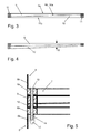
- Fig. 2 to Fig. 4 show the superimposed ring parts 9, 10 in detail.
- the ring parts are not cylindrical rings because an upper surface 9a, 10a and a lower surface 9b, 10b of the ring parts 9, 10 lie in mutually inclined planes, respectively.
- the inclination angle of the levels is presently about 1 °. Accordingly, each of the ring parts has a position of the smallest axial thickness of about 10 cm in the present case and a point of greatest thickness of about 21.3 cm in the present case.
- Fig. 3 the two ring parts are oriented in opposite directions.
- the inclinations of the surfaces compensate each other, so that the upper surface 9a and the lower surface 10b of the stack of Ring parts are parallel to each other.
- no skew of the structures is compensated, and the ring parts have at best the function of an intermediate piece.
- the ring parts can also be omitted in such a case, so that the flange rings 6a, 8a are placed directly on each other.
- Fig. 4 is one of the ring parts compared to Fig. 3 rotated by 180 ° about a central axis, so that a maximum inclination angle W of the surfaces 9a and 10b to each other by 2 ° results. Accordingly, in the present example, a maximum angle of incidence of the tower base 3 can be compensated by 2 °, wherein in principle all intermediate values of 0 ° to 2 ° are adjustable.
- each of the flange rings 6a, 8a protrudes radially inwardly from the cylindrical walls 6b, 8b, the ring parts 9, 10 and the flange rings 6a, 8a being flush.
- the outer wall 6b, 8b of the tower is also substantially smooth in the region of the flange 7.
- prefabricated sets of spacer members 14 are provided in order to manage with as few as possible different lengths of screws 12.
- sealing means between the components of the flange may be provided to prevent ingress of seawater in the tower.
- welding of the flange parts can also be provided.
Landscapes
- Engineering & Computer Science (AREA)
- General Engineering & Computer Science (AREA)
- Mechanical Engineering (AREA)
- Life Sciences & Earth Sciences (AREA)
- Sustainable Energy (AREA)
- Combustion & Propulsion (AREA)
- Chemical & Material Sciences (AREA)
- Sustainable Development (AREA)
- Civil Engineering (AREA)
- Structural Engineering (AREA)
- General Life Sciences & Earth Sciences (AREA)
- Mining & Mineral Resources (AREA)
- Paleontology (AREA)
- Wind Motors (AREA)
Abstract
Description
- Die Erfindung betrifft einen Flansch für einen Turm einer Windkraftanlage nach dem Oberbegriff des Anspruchs 1 sowie einen Turm einer Windkraftanlage mit einem erfindungsgemäßen Flansch und ein Verfahren zur Herstellung einer Windkraftanlage.
- Aus der Praxis des Baus von Windkraftanlagen sind Türme bekannt, bei denen ringförmige Flanschteile an rohrförmige Abschnitte des Turms angeschweißt sind. Mittels der Flanschteile werden die einzelnen Abschnitte der Türme untereinander verbunden oder es erfolgt die Verbindung mit einer Turmbasis oder mit einem Turmkopf.
-
DE 10 2011 052 845 A1 beschreibt einen Turm für eine Windkraftanlage, bei dem ein Schiefstand eines unteren Rohrteils gegenüber der Senkrechten dadurch kompensiert wird, dass zumindest ein Flanschring an einem oberen Rohrteil mit einer Neigung gegenüber einer Mittelachse des oberen Rohrteils an dem oberen Rohrteil verschweißt wird. - Es ist die Aufgabe der Erfindung, einen Flansch anzugeben, der eine einfache Montage einer Windkraftanlage ermöglicht.
- Diese Aufgabe wird für einen eingangs genannten Flansch erfindungsgemäß mit den kennzeichnenden Merkmalen des Anspruchs 1 gelöst. Durch die wählbare Orientierung des zumindest einen Ringteils mit seinen geneigten Oberflächen kann dabei eine Neigung zwischen einer Achse der ersten Struktur und einer Achse der zweiten Struktur zumindest in gewissen Umfang kompensiert werden.
- Dies kann zum Beispiel bei Offshore-Windkraftanlagen eine Kosten und Zeit sparende Maßnahme darstellen. Bei Offshore-Anlagen wird regelmäßig eine Turmbasis in einem Gewässergrund verankert, wonach weitere Turmteile und zuletzt der Windgenerator montiert werden. Die Verankerung der Turmbasis erfolgt meist von schwimmenden Montageplattformen und führt häufig zunächst zu einer schiefen bzw. bezüglich der Senkrechten ungenügend orientierten verankerten Turmbasis. Es ist für solche Fälle bekannt, einen aufwendigen Korrekturschritt durchzuführen, indem die bereits verankerte Basis durch hohe Kräfte, z.B. mit Spezialschiffen, hydraulischen Großgeräten etc., nachjustiert werden muss. Durch Verwendung eines erfindungsgemäßen Flansches in der Konstruktion des Turmes kann ein solcher Schiefstand innerhalb des Turmes kompensiert werden. Zumindest kann der Toleranzbereich für den Schiefstand der Turmbasis erheblich erweitert werden, was die Montage des Turmes wesentlich vereinfacht.
- Grundsätzlich kann ein erfindungsgemäßer Flansch aber auch für landgestützte Windkraftanlagen Verwendung finden. Hierdurch können zu geringen Kosten Toleranzbereiche für Schiefstände von Fundamenten und/oder Turmteilen vergrößert werden.
- Durch die Verwendung eines geschlossenen Ringteils zum Ausgleich des Schiefstandes kann der Flansch auf einfache Weise umlaufend wetterdicht ausgebildet sein.
- Ein Ringteil eines erfindungsgemäßen Flansches ist in bevorzugter Detailgestaltung kreisringförmig. Bei anderen Ausführungsformen kann aber auch ein polygonal geformtes Ringteil, zum Beispiel als Achteck, Zwölfeck etc. vorliegen. Bestimmte Türme für Windkraftanlagen werden mit polygonalen Querschnitten hergestellt, für die solche polygonalen Ringteile zweckmäßig verwendbar sind.
- Bei einer einfachen Realisierung der Erfindung kann der Schiefstand mit nur einem Ringteil mit zueinander geneigten Oberflächen ausgeglichen werden. Hierzu muss die Neigung der Oberflächen des Ringteils der Größe des Schiefstandes entsprechen, so dass die Richtung des Schiefstandes noch durch die Wahl der Orientierung des Ringteils einzustellen ist. In der Praxis könnte hierzu ein Satz von verschiedenen Ringteilen mit verschiedenen Winkeln bereit gehalten werden.
- Eine allgemein bevorzugte Gestaltung der Erfindung sieht dagegen vor, zumindest zwei Ringteile zu verwenden, die übereinander angeordnet sind. Eine unmittelbare Stapelung der Ringteile aufeinander ist dabei nicht notwendig, kann aber zweckmäßig sein. Bei einer solchen Anordnung kann ein Schiefstand durch geeignete Wahl der Orientierungen jedes der Ringteile sowohl bezüglich der Richtung als auch der Größe des Schiefstandes kompensiert werden. Die maximale Winkelgröße, bis zu der ein Schiefstand korrigierbar ist, folgt aus der genauen Formgebung der Ringteile, insbesondere der Neigungswinkel ihrer Oberflächen. Sofern nachfolgend "zumindest ein" Ringteil des erfindungsgemäßen Flansches benannt wird, ist jeweils besonders vorteilhaft das Vorsehen von zumindest zwei Ringteilen möglich.
- Falls die Ringteile nicht wie bevorzugt kreisförmig, sondern polygonal ausgebildet sind, so können Schiefstände zweckmäßig um Stufen von Winkeln korrigiert werden, die der polygonalen Form der Ringteile entsprechen, also zum Beispiel eine Drehung der Ringteile um eine kleinste Stufe von 360°:12 = 30° bei einer zwölfeckigen Ausführung der Ringteile.
- Unter der ersten Struktur und der zweiten Struktur sind im Sinne der Erfindung grundsätzlich sämtliche Bauteile des Turmes zu verstehen, die übereinander angeordnet sind. Die erste Struktur des Turmes kann zum Beispiel eine Turmbasis sein, worunter auch ein Fundament des Turmes verstanden wird. Eine solche Turmbasis kann je nach Ausgestaltung auch einen rohrförmigen Abschnitt als Anschluss für die weiteren Turmteile haben. Die zweite Struktur kann zum Beispiel ein rohrförmiger Abschnitt des Turmes sein, der auf den ersten Abschnitt aufgebaut ist.
- Bei einer erfindungsgemäßen Ausführungsform der Erfindung ist das zumindest eine Ringteil zwischen zwei Flanschringen angeordnet, wobei der erste Flanschring an der ersten Struktur und der zweite Flanschring an der zweiten Struktur festgelegt ist. Dies ermöglicht Orientierung des Ringteils oder der mehreren Ringteile gegenüber den Strukturen. Bei Vorliegen von zwei oder mehr Ringteilen kann unabhängig von einer gewählten Orientierung der Strukturen in Drehrichtung ein Schiefstand der Richtung und der Größe nach kompensiert werden. Die Flanschringe sind dabei an den auszurichtenden Strukturen festgelegt, zum Beispiel mittels Verschweißung. Diese Anordnung kann zum Beispiel als an sich herkömmlicher Flansch ausgebildet sein, bei dem die Ringteile zwischen die Flanschringe gelegt werden.
- Bevorzugt sind die Flanschringe kreisförmig. Bei einer möglichen polygonalen Form des Turmes sind die Flanschringe wie auch die Ringteile zweckmäßig polygonal geformt.
- Bei einer möglichen Weiterbildung können die Ringteile als optionale, aber nicht notwendige Einlage zwischen den Flanschringen vorgesehen sein. Somit bräuchte auf die Ringteile nur im Fall eines eine Toleranz überschreitenden Schiefstandes zurückgegriffen werden, und die Ringteile könnten im Fall einer bereits ausreichenden Ausrichtung der Strukturen zur Kostenersparnis weggelassen werden.
- Bei vorbekannten Ausführungsformen gemäß der eingangs genannten
DE 10 2011 052 845 A1 ist zumindest eines der Ringteile unmittelbar an einer der Strukturen festgelegt, zum Beispiel mittels Verschweißung. Wenn zum Beispiel die Drehorientierung einer der Strukturen irrelevant ist, zum Beispiel im Falle eines sonst drehsymmetrischen, rohrförmigen Turmabschnitts, dann kann die gesamte Struktur mit dem Ringteil und seiner geneigten Oberfläche in eine erste gewünschte Orientierung gedreht werden. Das zweite Ringteil kann dann in eine zweite gewünschte Orientierung gedreht werden, um die weitere Kompensation der Neigung zu erzielen. Bei einer solchen Anordnung nach dem Stand der Technik sind die fest angeordneten Ringteile als Flanschringe mit einer geneigten Oberfläche ausgebildet - Allgemein vorteilhaft hat das zumindest eine Ringteil jeweils eine Mehrzahl von über seinen Umfang verteilten Durchbrechungen, mittels derer eine einfache Montage erfolgen kann. Bevorzugt durchgreift dabei ein Satz von Befestigungsgliedern, insbesondere Schrauben, die Durchbrechungen zur Festlegung der ersten Struktur an der zweiten Struktur. Anzahl und Abstände der Durchbrechungen und Schrauben können dabei an herkömmlichen Schraubflanschen orientiert sein. Grundsätzlich können die Ringteile zur Kostenersparnis auch ohne die Durchbrechungen ausgebildet sein. Bei einer solchen Ausführungsform könnte zum Beispiel ein Kranz von Schrauben, die angrenzende Flanschringe miteinander verbinden, an einem Außenumfang oder einem Innenumfang der Ringteile verlaufen, um diese so in radialer Richtung in Position zu halten. Bei wiederum anderen Ausführungsformen kann auf Durchbrechungen und/oder Befestigungsmittel verzichtet werden, wobei die Ringteile zum Beispiel nach ihrer Ausrichtung mit den angrenzenden Strukturen verschweißt werden.
- In bevorzugter Weiterbildung einer Ausführungsform mit einer Mehrzahl von Befestigungsgliedern ist es bevorzugt vorgesehen, dass eine Mehrzahl von insbesondere hülsenförmigen Abstandsgliedern verschiedener Länge vorgesehen ist, wobei die Abstandsglieder an den Befestigungsgliedern angeordnet sind. Hierdurch lassen sich Distanzen zwischen den Befestigungsgliedern und Widerlagern auf einfache Weise kompensieren. Zum Beispiel werden erst nach Ausrichtung der Ringteile die benötigten Anzahlen von jeweiligen Schraubenlängen für eine Verschraubung bekannt. Andererseits sind die zur Verschraubung solcher Strukturen zulässigen Schrauben regelmäßig hochfeste Spezialschrauben, die aufgrund der Herstellungstechnik meist nur eine begrenzte Gewindelänge aufweisen. Bei Vorsehen eines entsprechenden Satzes von Abstandsgliedern bzw. einfachen Abstandshülsen kann eine Montage dennoch bei jeder Ausrichtung der Ringteile mit nur einer oder wenigen verschiedenen Schraubenlängen erfolgen.
- Allgemein vorteilhaft ist es vorgesehen, dass der Winkel zwischen den zueinander geneigten Oberflächen des zumindest einen Ringteils zwischen 0,4 ° und 3° beträgt. Hierdurch kann ein praxisrelevanter Bereich von Schiefständen gut ausgeglichen werden.
- Der erfindungsgemäße Flansch betrifft vor allem Großanlagen, weshalb ein bevorzugter Außendurchmesser des Ringteils wenigstens 4 Meter beträgt.
- Allgemein vorteilhaft können zwei oder mehr Ringteile eines erfindungsgemäßen Flansches zur Kostenersparnis als Gleichteile ausgebildet sein.
- Die Erfindung betrifft zudem einen Turm einer Windkraftanlage, umfassend einen erfindungsgemäßen Flansch. Besonders bevorzugt ist dabei die erste Struktur des Turms als in einem Gewässergrund verankerte Turmbasis und die zweite Struktur als ein oberhalb der Turmbasis erstreckter, insbesondere rohrförmiger Abschnitt des Turms ausgebildet. Beim Bau von in Gewässern verankerten Windkraftanlagen (Offshore-Windkraftanlagen) treten besonders häufig Probleme mit einer ausreichenden Ausrichtung der Turmbasis auf, so dass der erfindungsgemäße Flansch eine erhebliche Vereinfachung bei der Montage des Turms ermöglicht.
- Die Erfindung betrifft zudem ein Verfahren zur Herstellung einer Windkraftanlage mit einem erfindungsgemäßen Turm nach einem der Ansprüche 8 oder 9, umfassend die Schritte:
- a. Bereitstellen einer ortsfest verankerten Turmbasis mit einem oberen Anschlussglied;
- b. Bestimmen einer Abweichung einer Ausrichtung des Anschlussgliedes bezüglich der Senkrechten;
- c. Anbringen und Ausrichten des zumindest einen Ringteils zur Kompensation der in Schritt b. bestimmten Abweichung des Anschlussgliedes;
- d. Anbringen eines Abschnitts des Turmes über dem Anschlussglied und dem Ringteil.
- Bevorzugt werden zumindest zwei Ringteile verwendet, die in Schritt c. zur Kompensation der Abweichung sowohl nach Richtung als auch nach Größe positioniert werden.
- Bei einer besonders bevorzugten Weiterbildung wird das zumindest eine Ringteil an einem Aufstellort des Turms bereit gehalten, bevor mit der Verankerung der Turmbasis begonnen wird. Dies erlaubt eine schnelle und unterbrechungsarme Montage von Türmen, insbesondere Offshore-Türmen. Häufig werden mehrere Türme eines Feldes von Windkraftanlagen parallel oder nacheinander gebaut. Es stellt in einer Mischkalkultaion einen großen logistischen und technischen Vorteil dar, wenn das Ringteil bzw. die zwei Ringteile bei Auftreten eines Schiefstandes einer Turmbasis sofort am Ort der Baustelle zur Verfügung stehen. Dabei ist weiter zu berücksichtigen, dass die Ringteile bei großen Turmdurchmessern nur langwierig von Spezialtransportern bewegt werden können. Die Anzahl der an der Baustelle bereit gehaltenen Ringteile oder Paare von Ringteilen kann von einer statistischen Häufigkeit des Auftretens von Schiefständen bzw. Korrekturerfordernissen abhängig gemacht werden.
- Das Anschlussglied des Turmes kann ein beliebiges Bauteil sein, das einen zum weiteren Aufbau des Turms definierten Bereich aufweist. Zum Beispiel kann es sich bei einer Monopile-Bauweise der Turmbasis um ein Übergangsstück der Turmbasis handeln, das als oberen Abschluss einen Flanschring umfasst.
- Der Turm der Windkraftanlage kann auf beliebige Weise ausgebildet sein, zum Beispiel als Rohrturm in Monopile-Bauweise, in Jacket-Bauweise, in Tripile-Bauweise oder auch in Tripod-Bauweise. Zweckmäßig liegt zumindest ein rohrförmiger Abschnitt vor, der mittels eines erfindungsgemäßen Flansches verbunden ist.
- Weitere Vorteile und Merkmale der Erfindung ergeben sich aus dem nachfolgend beschriebenen Ausführungsbeispiel sowie aus den abhängigen Ansprüchen.
- Nachfolgend wird ein bevorzugtes Ausführungsbeispiel der Erfindung beschrieben und anhand der anliegenden Zeichnungen näher erläutert.
- Fig. 1
- zeigt eine schematische Ansicht eines erfindungsgemäßen Offshore-Windturmes mit einer Turmbasis in Monopile-Bauweise.
- Fig. 2
- zeigt eine Draufsicht auf zwei Ringteile eines erfindungsgemäßen Flansches.
- Fig. 3
- zeigt eine Schnittansicht durch die Ringteile aus
Fig. 2 entlang der Linie A-A in einer ersten Ausrichtung. - Fig. 4
- zeigt eine Schnittansicht durch die Ringteile aus
Fig. 2 entlang der Linie A-A in einer zweiten Ausrichtung. - Fig. 5
- zeigt eine schematische, nicht maßstabsgerechte Schnittansicht eines erfindungsgemäßen Flansches in einem montierten Zustand.
- Die in
Fig. 1 gezeigte Windkraftanlage umfasst einen Turm 1, auf dessen oberes Ende ein Windgenerator 2 aufgesetzt ist. Der Turm 1 umfasst eine Turmbasis 3, mit der er unterhalb einer Wasseroberfläche 4 in einem Gewässerboden bzw. Meeresboden 5 verankert ist. Sofern nicht anders bezeichnet, bestehen die nachfolgend beschriebenen Bauteile aus Stahl. - Die Verankerung erfolgt vorliegend durch Einrammen eines Rohres der Turmbasis in den Meeresboden, wonach das überstehende Rohr mit Füllmittel wie etwa Beton gefüllt und ein Übergangsstück 6 (Fachbegriff: Transition Piece) als Bestandteil der Turmbasis aufgesetzt wird. Durch das Rohr mit dem Übergangsstück 6 wird insgesamt eine erste, untere Struktur des Turmes 1 ausgebildet, die je nach Verlauf des Eintreibvorgangs einen Schiefstand gegenüber der Senkrechten bzw. Schwerkraftrichtung aufweisen kann.
- Über dem Übergangsstück 6 der Turmbasis 3 wird dann der weitere Turm aufgebaut, der vorliegend einen rohrförmigen Abschnitt 8 als eine zweite, obere Struktur aufweist. Zuletzt wird der Windgenerator 2 aufgebaut.
- Zwischen der ersten Struktur 3 und der zweiten Struktur 8 ist ein Flansch 7 (siehe auch
Fig. 5 ) angeordnet, der die beiden Strukturen unter Korrektur des Schiefstandes miteinander verbindet. Insbesondere kann dadurch die zweite Struktur 8 eine senkrechte Ausrichtung trotz eines Schiefstandes der ersten Struktur 3 aufweisen. - Der Flansch 7 umfasst vorliegend einen ersten Flanschring 8a, der mit einer nach oben fortgesetzten Wand 8b des Rohrabschnitts 8 fest verschweißt ist. Ferner umfasst der Flansch 7 einen zweiten, unteren Flanschring 6a, der mit einer Wand 6b des Übergangsstücks 6 der Turmbasis 3 verschweißt ist.
- Zwischen den Flanschringen 6a, 8a sind ein erstes Ringteil 9 und ein zweites Ringteil 10 angeordnet, wobei die Ringteile 9, 10 unmittelbar aufeinander aufliegen. Die Ringteile 9, 10 sind vorliegend als baugleiche Teile ausgebildet. Sie umfassen jeweils einen Ring aus Stahl mit einem Außendurchmesser von rund 6,5 m und einem Innendurchmesser von 6 m.
-
Fig. 2 bis Fig. 4 zeigen die aufeinander liegenden Ringteile 9, 10 im Detail. Die Ringteile sind keine zylindrischen Ringe, da eine obere Oberfläche 9a, 10a und eine untere Oberfläche 9b, 10b der Ringteile 9, 10 jeweils in zueinander geneigten Ebenen liegen. Der Neigungswinkel der Ebenen beträgt vorliegend etwa 1 °. Demnach hat jedes der Ringteile eine Stelle kleinster axialer Dicke von vorliegend etwa 10 cm und eine Stelle größter Dicke von vorliegend etwa 21,3 cm. - In
Fig. 3 sind die beiden Ringteile gegenläufig orientiert aufeinander gelegt. Die Neigungen der Oberflächen kompensieren sich dabei, so dass die obere Oberfläche 9a und die untere Oberfläche 10b des Stapels von Ringteilen parallel zueinander sind. Bei dieser Anordnung wird kein Schiefstand der Strukturen kompensiert, und die Ringteile haben allenfalls die Funktion eines Zwischenstücks. Je nach Anforderungen können die Ringteile in einem solchen Fall auch weggelassen werden, so dass die Flanschringe 6a, 8a unmittelbar aufeinander gesetzt werden. - In
Fig. 4 ist eines der Ringteile im Vergleich zuFig. 3 um 180° um eine zentrale Achse gedreht, so dass ein maximaler Neigungswinkel W der Oberflächen 9a und 10b zueinander von 2° resultiert. Entsprechend kann im vorliegenden Beispiel ein maximaler Schiefstand der Turmbasis 3 von 2° kompensiert werden, wobei im Prinzip sämtliche Zwischenwerte von 0° bis 2° einstellbar sind. - Im vorliegenden Beispiel haben sowohl die Flanschringe 6a, 8a als auch die Ringteile 9, 10 umlaufend gleich beabstandete Durchbrechungen bzw. Bohrungen 11, durch die Schrauben als Befestigungsmittel zum Anziehen des Flansches gesteckt sind. Entsprechend lassen sich die Ringteile 9, 10 im vorliegenden Beispiel nur in Vielfachen der Beabstandung der Schrauben verdrehen, was aufgrund der großen Anzahl von 132 Bohrungen 11 (= 2,7° Winkelabstand) ausreichend genau erfolgend kann.
- Jeder der Flanschringe 6a, 8a ragt ausgehend von den zylindrischen Wänden 6b, 8b radial nach innen vor, wobei die Ringteile 9, 10 und die Flanschringe 6a, 8a bündig abschließen. Somit verläuft die Außenwand 6b, 8b des Turms auch im Bereich des Flansches 7 im Wesentlichen glatt.
- Zur Festlegung des Flansches 7 sind durch die überdeckenden Bohrungen 11 der Flanschringe und Ringteile 6a, 8a, 9, 10 jeweils Schrauben 12 gesteckt und mit Muttern 13 verschlossen. Bei den Schrauben handelt es sich um hochfeste HV-Schrauben nach internationaler technischer Norm. Da diese Schauben nicht immer in beliebigen Größen zur Verfügung stehen, werden je nach Einstellung der Ringteile 9, 10 Abstandsglieder 14 in Form von Stahlhülsen eingesetzt.
- Zweckmäßig werden vorkonfektionierte Sätze von Abstandsgliedern 14 bereitgestellt, um mit möglichst wenigen verschiedenen Längen von Schrauben 12 auszukommen.
- Es versteht sich, dass je nach Anforderungen Dichtungsmittel zwischen den Bauteilen des Flansches vorgesehen sein können, um ein Eindringen von Seewasser in den Turm zu verhindern. Alternativ oder ergänzend können auch Verschweißungen der Flanschteile vorgesehen sein.
Claims (10)
- Flansch für einen Turm einer Windkraftanlage, umfassend zumindest ein, insbesondere zwei um eine Achse (A) des Turms (1) orientierte Ringteile (9, 10),
wobei das zumindest eine Ringteil (9, 10) zwischen einer ersten, unterhalb des Ringteils angeordneten Struktur (3, 6) des Turms (1) und einer zweiten, oberhalb des Ringteils (9, 10) angeordneten Struktur (8) des Turms (1) angeordnet ist,
dadurch gekennzeichnet,
dass das Ringteil (9, 10) jeweils eine erste Oberfläche (9a, 10a) und eine gegenüberliegende zweite Oberfläche (9b, 10b) aufweist, wobei die Oberflächen (9a, 9b; 10a, 10b) in zueinander um einen Winkel geneigten Ebenen liegen,
wobei das zumindest eine Ringteil (9, 10) zur Einstellung einer Neigung der ersten Struktur (3, 6) zu der zweiten Struktur (8) verdrehbar positionierbar ist, und wobei das Ringteil (9, 10) zwischen zwei Flanschringen (6a, 8a) angeordnet ist, wobei der erste Flanschring (6a) an der ersten Struktur (3, 6) und der zweite Flanschring (8a) an der zweiten Struktur (8) festgelegt ist. - Flansch nach Anspruch 1, dadurch gekennzeichnet, dass das Ringteil (9, 10) eine Mehrzahl von über seinen Umfang verteilten Durchbrechungen (11) aufweist.
- Flansch nach Anspruch 2, dadurch gekennzeichnet, dass ein Satz von Befestigungsgliedern (12, 13), insbesondere Schrauben, die Durchbrechungen (11) zur Festlegung der ersten Struktur (3, 6) an der zweiten Struktur (8) durchgreift.
- Flansch nach Anspruch 3, dadurch gekennzeichnet, dass eine Mehrzahl von insbesondere hülsenförmigen Abstandsgliedern (14) verschiedener Länge vorgesehen ist, wobei die Abstandsglieder (14) an den Befestigungsgliedern (12, 13) angeordnet sind.
- Flansch nach einem der vorhergehenden Ansprüche, dadurch gekennzeichnet, dass der Winkel zwischen den zueinander geneigten Oberflächen (9a, 9b; 10a, 10b) des Ringteils (9, 10) zwischen 0,4 ° und 3° beträgt.
- Flansch nach einem der vorhergehenden Ansprüche, dadurch gekennzeichnet, dass ein Außendurchmesser des Ringteils (9, 10) wenigstens 4 Meter beträgt.
- Turm einer Windkraftanlage, umfassend einen Flansch (7) nach einem der vorhergehenden Ansprüche.
- Turm nach Anspruch 7, wobei die erste Struktur des Turms (1) als in einem Gewässergrund verankerte Turmbasis (3, 6) und die zweite Struktur als ein oberhalb der Turmbasis (3, 6) erstreckter, insbesondere rohrförmiger Abschnitt (8) des Turms (1) ausgebildet ist.
- Verfahren zur Herstellung einer Windkraftanlage mit einem Turm (1) nach einem der Ansprüche 7 oder 8, umfassend die Schritte:a. Bereitstellen einer ortsfest verankerten Turmbasis (3, 6) mit einem oberen Anschlussglied (6);b. Bestimmen einer Abweichung einer Ausrichtung des Anschlussgliedes (6) bezüglich der Senkrechten;c. Anbringen und Ausrichten des zumindest einen Ringteils(9, 10), insbesondere zweier Ringteile (9, 10), zur Kompensation der in Schritt b. bestimmten Abweichung des Anschlussgliedes (6);d. Anbringen eines Abschnitts (8) des Turmes über dem Anschlussglied (6) und dem Ringteil (9, 10).
- Verfahren nach Anspruch 9, dadurch gekennzeichnet, dass das zumindest eine Ringteil (9, 10) an einem Aufstellort des Turms bereit gehalten wird, bevor mit der Verankerung der Turmbasis (3, 6) begonnen wird.
Applications Claiming Priority (1)
| Application Number | Priority Date | Filing Date | Title |
|---|---|---|---|
| DE102012016843.8A DE102012016843A1 (de) | 2012-08-27 | 2012-08-27 | Justierbarer Flansch für einen Turm einer Windkraftanlage |
Publications (3)
| Publication Number | Publication Date |
|---|---|
| EP2708659A2 true EP2708659A2 (de) | 2014-03-19 |
| EP2708659A3 EP2708659A3 (de) | 2014-06-11 |
| EP2708659B1 EP2708659B1 (de) | 2017-11-15 |
Family
ID=48874776
Family Applications (1)
| Application Number | Title | Priority Date | Filing Date |
|---|---|---|---|
| EP13176396.3A Not-in-force EP2708659B1 (de) | 2012-08-27 | 2013-07-12 | Justierbarer Flansch für einen Turm einer Windkraftanalge |
Country Status (2)
| Country | Link |
|---|---|
| EP (1) | EP2708659B1 (de) |
| DE (2) | DE102012016843A1 (de) |
Cited By (4)
| Publication number | Priority date | Publication date | Assignee | Title |
|---|---|---|---|---|
| CN108397356A (zh) * | 2018-03-23 | 2018-08-14 | 健安诚(内蒙古)新能源科技有限公司 | 智能可更换锚栓的风机基础及智能取杆机器人 |
| EP3742035A1 (de) * | 2019-05-23 | 2020-11-25 | Siemens Aktiengesellschaft | Anordnung |
| CN113272583A (zh) * | 2019-01-09 | 2021-08-17 | Abb瑞士股份有限公司 | 用于在联接面与参考面之间气密连接的装置 |
| RU2792714C1 (ru) * | 2019-05-23 | 2023-03-23 | Сименс Акциенгезелльшафт | Устройство для компенсации смещения между двумя фланцами труб и способ компенсации смещения между двумя фланцами труб |
Families Citing this family (1)
| Publication number | Priority date | Publication date | Assignee | Title |
|---|---|---|---|---|
| US10767632B2 (en) * | 2016-09-09 | 2020-09-08 | Siemens Gamesa Renewable Energy A/S | Transition piece for a wind turbine |
Citations (1)
| Publication number | Priority date | Publication date | Assignee | Title |
|---|---|---|---|---|
| DE102011052845A1 (de) | 2010-08-27 | 2012-03-01 | General Electric Co. | Windkraftanlagen-Turmsegment, Windkraftanlage und Verfahren zum Errichten einer Windkraftanlage |
Family Cites Families (2)
| Publication number | Priority date | Publication date | Assignee | Title |
|---|---|---|---|---|
| DE1695629U (de) * | 1955-01-31 | 1955-03-31 | Trox Gmbh Geb | Aus mehreren stahlbetonrohren zusammengesetzter roehrkoerper. |
| DE1802563A1 (de) * | 1967-10-12 | 1969-06-19 | Atomic Power Const Ltd | Verbindung zweier axial fehlausgerichteteter Rohre |
-
2012
- 2012-08-27 DE DE102012016843.8A patent/DE102012016843A1/de not_active Withdrawn
-
2013
- 2013-07-12 EP EP13176396.3A patent/EP2708659B1/de not_active Not-in-force
- 2013-07-12 DE DE202013012183.1U patent/DE202013012183U1/de not_active Expired - Lifetime
Patent Citations (1)
| Publication number | Priority date | Publication date | Assignee | Title |
|---|---|---|---|---|
| DE102011052845A1 (de) | 2010-08-27 | 2012-03-01 | General Electric Co. | Windkraftanlagen-Turmsegment, Windkraftanlage und Verfahren zum Errichten einer Windkraftanlage |
Cited By (11)
| Publication number | Priority date | Publication date | Assignee | Title |
|---|---|---|---|---|
| CN108397356A (zh) * | 2018-03-23 | 2018-08-14 | 健安诚(内蒙古)新能源科技有限公司 | 智能可更换锚栓的风机基础及智能取杆机器人 |
| CN108397356B (zh) * | 2018-03-23 | 2024-05-24 | 健安诚(内蒙古)新能源科技有限公司 | 一种包括智能可更换锚栓的风机基础及智能取杆机器人的装置 |
| CN113272583A (zh) * | 2019-01-09 | 2021-08-17 | Abb瑞士股份有限公司 | 用于在联接面与参考面之间气密连接的装置 |
| CN113272583B (zh) * | 2019-01-09 | 2022-12-23 | Abb瑞士股份有限公司 | 用于在联接面与参考面之间气密连接的装置 |
| US11815203B2 (en) | 2019-01-09 | 2023-11-14 | Abb Schweiz Ag | Device for gas-tight connection between a connection surface and a reference surface |
| EP3742035A1 (de) * | 2019-05-23 | 2020-11-25 | Siemens Aktiengesellschaft | Anordnung |
| WO2020233926A1 (de) * | 2019-05-23 | 2020-11-26 | Siemens Aktiengesellschaft | Anordnung |
| CN113939681A (zh) * | 2019-05-23 | 2022-01-14 | 西门子股份公司 | 组件 |
| RU2792714C1 (ru) * | 2019-05-23 | 2023-03-23 | Сименс Акциенгезелльшафт | Устройство для компенсации смещения между двумя фланцами труб и способ компенсации смещения между двумя фланцами труб |
| CN113939681B (zh) * | 2019-05-23 | 2023-11-10 | 西门子股份公司 | 组件 |
| US11885446B2 (en) | 2019-05-23 | 2024-01-30 | Siemens Aktiengesellschaft | Arrangement |
Also Published As
| Publication number | Publication date |
|---|---|
| EP2708659A3 (de) | 2014-06-11 |
| EP2708659B1 (de) | 2017-11-15 |
| DE202013012183U1 (de) | 2015-07-14 |
| DE102012016843A1 (de) | 2014-02-27 |
Similar Documents
| Publication | Publication Date | Title |
|---|---|---|
| EP2824257B2 (de) | Verfahren zur Herstellung und zum Errichten eines Rohrturmbauwerks | |
| EP2239376B1 (de) | Verankerungsbauteil für einen Windenergieanlagenturm | |
| EP3092357B1 (de) | Anordnung mit einem betonfundament und einem turm und verfahren zum errichten eines turms | |
| EP2764185B1 (de) | Verfahren zum errichten eines turmbauwerks sowie turmbauwerk | |
| EP2522780B1 (de) | Offshore-Fundament für Windenergieanlagen | |
| EP2494188B1 (de) | Verfahren für die erstellung eines strömungskraftwerks | |
| EP3262240B1 (de) | Windenergieanlagen-fundament und windenergieanlage | |
| EP3092358B2 (de) | Windenergieanlage mit turm und fundament aus mehreren segmenten | |
| EP3491239B1 (de) | Verbindungselement zum verbinden von turmabschnitten, turmabschnitt, turm, windenergieanlage sowie verfahren zum herstellen eines turmabschnitts und zum verbinden von turmabschnitten | |
| EP3230539B1 (de) | Verfahren zum errichten eines rohrturmbauwerks und rohrturmbauwerk | |
| DE102012104508A1 (de) | Turmbauwerk einer Windkraftanlage sowie Verfahren zum Errichten eines Turmbauwerks | |
| DE102011052845A1 (de) | Windkraftanlagen-Turmsegment, Windkraftanlage und Verfahren zum Errichten einer Windkraftanlage | |
| EP2708659B1 (de) | Justierbarer Flansch für einen Turm einer Windkraftanalge | |
| EP4491835A2 (de) | Turm mit konischen stahladapterelementen | |
| EP3658771B1 (de) | Windenergieanlagen-stahlturmabschnitt für einen windenergieanlagen-turm und verfahren zur herstellung | |
| EP2288771B1 (de) | Turm einer windenergieanlage | |
| EP2692967A2 (de) | Verfahren zum Errichten eines Turmes aus Stahl einer Windenergieanlage und Turm aus Stahl für eine Windenergieanlage | |
| DE102017120487A1 (de) | Turm einer Windenergieanlage und Verfahren zum Herstellen eines Sektionssegments für einen solchen Turm | |
| DE29809541U1 (de) | Vorrichtung zum Herstellen von hohen, hohlen, turmartigen Bauwerken von zweihundert Metern Höhe und mehr, insbesondere von Türmen für Windkraftanlagen | |
| EP3495589A1 (de) | Turm einer windenergieanlage, verfahren zum errichten eines turms einer windenergieanlage, windenergieanlage | |
| WO2020114789A1 (de) | Verfahren zum vorspannen eines turms einer windenergieanlage | |
| EP3056611B1 (de) | Kopplungsvorrichtung zum verbinden einer tragstruktur mit einem fundament im meeresboden | |
| EP3051029B1 (de) | Gründungspfahl zum einvibrieren in einen baugrund | |
| EP3597829B1 (de) | Gründungsverstärkung für offshore-bauwerke | |
| DE202009018841U1 (de) | Bohrfundament mit zylindrischem Grundkörper |
Legal Events
| Date | Code | Title | Description |
|---|---|---|---|
| REG | Reference to a national code |
Ref country code: DE Ref legal event code: R138 Ref document number: 202013012183 Country of ref document: DE Free format text: GERMAN DOCUMENT NUMBER IS 502013008800 |
|
| PUAI | Public reference made under article 153(3) epc to a published international application that has entered the european phase |
Free format text: ORIGINAL CODE: 0009012 |
|
| AK | Designated contracting states |
Kind code of ref document: A2 Designated state(s): AL AT BE BG CH CY CZ DE DK EE ES FI FR GB GR HR HU IE IS IT LI LT LU LV MC MK MT NL NO PL PT RO RS SE SI SK SM TR |
|
| AX | Request for extension of the european patent |
Extension state: BA ME |
|
| PUAL | Search report despatched |
Free format text: ORIGINAL CODE: 0009013 |
|
| AK | Designated contracting states |
Kind code of ref document: A3 Designated state(s): AL AT BE BG CH CY CZ DE DK EE ES FI FR GB GR HR HU IE IS IT LI LT LU LV MC MK MT NL NO PL PT RO RS SE SI SK SM TR |
|
| AX | Request for extension of the european patent |
Extension state: BA ME |
|
| RIC1 | Information provided on ipc code assigned before grant |
Ipc: E02D 27/42 20060101AFI20140502BHEP Ipc: F03D 11/04 20060101ALI20140502BHEP Ipc: F03D 1/00 20060101ALI20140502BHEP |
|
| 17P | Request for examination filed |
Effective date: 20140512 |
|
| RBV | Designated contracting states (corrected) |
Designated state(s): AL AT BE BG CH CY CZ DE DK EE ES FI FR GB GR HR HU IE IS IT LI LT LU LV MC MK MT NL NO PL PT RO RS SE SI SK SM TR |
|
| GRAP | Despatch of communication of intention to grant a patent |
Free format text: ORIGINAL CODE: EPIDOSNIGR1 |
|
| RIC1 | Information provided on ipc code assigned before grant |
Ipc: F03D 13/35 20160101ALI20170425BHEP Ipc: E02B 17/00 20060101ALI20170425BHEP Ipc: F03D 13/20 20160101ALI20170425BHEP Ipc: E02D 27/42 20060101AFI20170425BHEP |
|
| GRAJ | Information related to disapproval of communication of intention to grant by the applicant or resumption of examination proceedings by the epo deleted |
Free format text: ORIGINAL CODE: EPIDOSDIGR1 |
|
| INTG | Intention to grant announced |
Effective date: 20170516 |
|
| GRAP | Despatch of communication of intention to grant a patent |
Free format text: ORIGINAL CODE: EPIDOSNIGR1 |
|
| INTG | Intention to grant announced |
Effective date: 20170613 |
|
| GRAS | Grant fee paid |
Free format text: ORIGINAL CODE: EPIDOSNIGR3 |
|
| GRAA | (expected) grant |
Free format text: ORIGINAL CODE: 0009210 |
|
| AK | Designated contracting states |
Kind code of ref document: B1 Designated state(s): AL AT BE BG CH CY CZ DE DK EE ES FI FR GB GR HR HU IE IS IT LI LT LU LV MC MK MT NL NO PL PT RO RS SE SI SK SM TR |
|
| REG | Reference to a national code |
Ref country code: CH Ref legal event code: EP Ref country code: GB Ref legal event code: FG4D Free format text: NOT ENGLISH Ref country code: AT Ref legal event code: REF Ref document number: 946417 Country of ref document: AT Kind code of ref document: T Effective date: 20171115 |
|
| REG | Reference to a national code |
Ref country code: IE Ref legal event code: FG4D Free format text: LANGUAGE OF EP DOCUMENT: GERMAN |
|
| REG | Reference to a national code |
Ref country code: DE Ref legal event code: R096 Ref document number: 502013008800 Country of ref document: DE |
|
| REG | Reference to a national code |
Ref country code: NL Ref legal event code: MP Effective date: 20171115 |
|
| REG | Reference to a national code |
Ref country code: LT Ref legal event code: MG4D |
|
| PG25 | Lapsed in a contracting state [announced via postgrant information from national office to epo] |
Ref country code: NO Free format text: LAPSE BECAUSE OF FAILURE TO SUBMIT A TRANSLATION OF THE DESCRIPTION OR TO PAY THE FEE WITHIN THE PRESCRIBED TIME-LIMIT Effective date: 20180215 Ref country code: NL Free format text: LAPSE BECAUSE OF FAILURE TO SUBMIT A TRANSLATION OF THE DESCRIPTION OR TO PAY THE FEE WITHIN THE PRESCRIBED TIME-LIMIT Effective date: 20171115 Ref country code: LT Free format text: LAPSE BECAUSE OF FAILURE TO SUBMIT A TRANSLATION OF THE DESCRIPTION OR TO PAY THE FEE WITHIN THE PRESCRIBED TIME-LIMIT Effective date: 20171115 Ref country code: ES Free format text: LAPSE BECAUSE OF FAILURE TO SUBMIT A TRANSLATION OF THE DESCRIPTION OR TO PAY THE FEE WITHIN THE PRESCRIBED TIME-LIMIT Effective date: 20171115 Ref country code: SE Free format text: LAPSE BECAUSE OF FAILURE TO SUBMIT A TRANSLATION OF THE DESCRIPTION OR TO PAY THE FEE WITHIN THE PRESCRIBED TIME-LIMIT Effective date: 20171115 Ref country code: FI Free format text: LAPSE BECAUSE OF FAILURE TO SUBMIT A TRANSLATION OF THE DESCRIPTION OR TO PAY THE FEE WITHIN THE PRESCRIBED TIME-LIMIT Effective date: 20171115 |
|
| PG25 | Lapsed in a contracting state [announced via postgrant information from national office to epo] |
Ref country code: HR Free format text: LAPSE BECAUSE OF FAILURE TO SUBMIT A TRANSLATION OF THE DESCRIPTION OR TO PAY THE FEE WITHIN THE PRESCRIBED TIME-LIMIT Effective date: 20171115 Ref country code: BG Free format text: LAPSE BECAUSE OF FAILURE TO SUBMIT A TRANSLATION OF THE DESCRIPTION OR TO PAY THE FEE WITHIN THE PRESCRIBED TIME-LIMIT Effective date: 20180215 Ref country code: RS Free format text: LAPSE BECAUSE OF FAILURE TO SUBMIT A TRANSLATION OF THE DESCRIPTION OR TO PAY THE FEE WITHIN THE PRESCRIBED TIME-LIMIT Effective date: 20171115 Ref country code: GR Free format text: LAPSE BECAUSE OF FAILURE TO SUBMIT A TRANSLATION OF THE DESCRIPTION OR TO PAY THE FEE WITHIN THE PRESCRIBED TIME-LIMIT Effective date: 20180216 Ref country code: LV Free format text: LAPSE BECAUSE OF FAILURE TO SUBMIT A TRANSLATION OF THE DESCRIPTION OR TO PAY THE FEE WITHIN THE PRESCRIBED TIME-LIMIT Effective date: 20171115 |
|
| REG | Reference to a national code |
Ref country code: FR Ref legal event code: PLFP Year of fee payment: 6 |
|
| PG25 | Lapsed in a contracting state [announced via postgrant information from national office to epo] |
Ref country code: CY Free format text: LAPSE BECAUSE OF FAILURE TO SUBMIT A TRANSLATION OF THE DESCRIPTION OR TO PAY THE FEE WITHIN THE PRESCRIBED TIME-LIMIT Effective date: 20171115 Ref country code: EE Free format text: LAPSE BECAUSE OF FAILURE TO SUBMIT A TRANSLATION OF THE DESCRIPTION OR TO PAY THE FEE WITHIN THE PRESCRIBED TIME-LIMIT Effective date: 20171115 Ref country code: CZ Free format text: LAPSE BECAUSE OF FAILURE TO SUBMIT A TRANSLATION OF THE DESCRIPTION OR TO PAY THE FEE WITHIN THE PRESCRIBED TIME-LIMIT Effective date: 20171115 Ref country code: SK Free format text: LAPSE BECAUSE OF FAILURE TO SUBMIT A TRANSLATION OF THE DESCRIPTION OR TO PAY THE FEE WITHIN THE PRESCRIBED TIME-LIMIT Effective date: 20171115 Ref country code: DK Free format text: LAPSE BECAUSE OF FAILURE TO SUBMIT A TRANSLATION OF THE DESCRIPTION OR TO PAY THE FEE WITHIN THE PRESCRIBED TIME-LIMIT Effective date: 20171115 |
|
| REG | Reference to a national code |
Ref country code: DE Ref legal event code: R097 Ref document number: 502013008800 Country of ref document: DE |
|
| PG25 | Lapsed in a contracting state [announced via postgrant information from national office to epo] |
Ref country code: PL Free format text: LAPSE BECAUSE OF FAILURE TO SUBMIT A TRANSLATION OF THE DESCRIPTION OR TO PAY THE FEE WITHIN THE PRESCRIBED TIME-LIMIT Effective date: 20171115 Ref country code: SM Free format text: LAPSE BECAUSE OF FAILURE TO SUBMIT A TRANSLATION OF THE DESCRIPTION OR TO PAY THE FEE WITHIN THE PRESCRIBED TIME-LIMIT Effective date: 20171115 Ref country code: RO Free format text: LAPSE BECAUSE OF FAILURE TO SUBMIT A TRANSLATION OF THE DESCRIPTION OR TO PAY THE FEE WITHIN THE PRESCRIBED TIME-LIMIT Effective date: 20171115 Ref country code: IT Free format text: LAPSE BECAUSE OF FAILURE TO SUBMIT A TRANSLATION OF THE DESCRIPTION OR TO PAY THE FEE WITHIN THE PRESCRIBED TIME-LIMIT Effective date: 20171115 |
|
| PLBE | No opposition filed within time limit |
Free format text: ORIGINAL CODE: 0009261 |
|
| STAA | Information on the status of an ep patent application or granted ep patent |
Free format text: STATUS: NO OPPOSITION FILED WITHIN TIME LIMIT |
|
| PG25 | Lapsed in a contracting state [announced via postgrant information from national office to epo] |
Ref country code: MT Free format text: LAPSE BECAUSE OF FAILURE TO SUBMIT A TRANSLATION OF THE DESCRIPTION OR TO PAY THE FEE WITHIN THE PRESCRIBED TIME-LIMIT Effective date: 20171115 |
|
| 26N | No opposition filed |
Effective date: 20180817 |
|
| PG25 | Lapsed in a contracting state [announced via postgrant information from national office to epo] |
Ref country code: SI Free format text: LAPSE BECAUSE OF FAILURE TO SUBMIT A TRANSLATION OF THE DESCRIPTION OR TO PAY THE FEE WITHIN THE PRESCRIBED TIME-LIMIT Effective date: 20171115 |
|
| REG | Reference to a national code |
Ref country code: CH Ref legal event code: PL |
|
| PG25 | Lapsed in a contracting state [announced via postgrant information from national office to epo] |
Ref country code: LU Free format text: LAPSE BECAUSE OF NON-PAYMENT OF DUE FEES Effective date: 20180712 Ref country code: MC Free format text: LAPSE BECAUSE OF FAILURE TO SUBMIT A TRANSLATION OF THE DESCRIPTION OR TO PAY THE FEE WITHIN THE PRESCRIBED TIME-LIMIT Effective date: 20171115 |
|
| REG | Reference to a national code |
Ref country code: BE Ref legal event code: MM Effective date: 20180731 |
|
| REG | Reference to a national code |
Ref country code: IE Ref legal event code: MM4A |
|
| PG25 | Lapsed in a contracting state [announced via postgrant information from national office to epo] |
Ref country code: CH Free format text: LAPSE BECAUSE OF NON-PAYMENT OF DUE FEES Effective date: 20180731 Ref country code: LI Free format text: LAPSE BECAUSE OF NON-PAYMENT OF DUE FEES Effective date: 20180731 Ref country code: IE Free format text: LAPSE BECAUSE OF NON-PAYMENT OF DUE FEES Effective date: 20180712 |
|
| PG25 | Lapsed in a contracting state [announced via postgrant information from national office to epo] |
Ref country code: BE Free format text: LAPSE BECAUSE OF NON-PAYMENT OF DUE FEES Effective date: 20180731 |
|
| REG | Reference to a national code |
Ref country code: AT Ref legal event code: MM01 Ref document number: 946417 Country of ref document: AT Kind code of ref document: T Effective date: 20180712 |
|
| PG25 | Lapsed in a contracting state [announced via postgrant information from national office to epo] |
Ref country code: AT Free format text: LAPSE BECAUSE OF NON-PAYMENT OF DUE FEES Effective date: 20180712 |
|
| PG25 | Lapsed in a contracting state [announced via postgrant information from national office to epo] |
Ref country code: TR Free format text: LAPSE BECAUSE OF FAILURE TO SUBMIT A TRANSLATION OF THE DESCRIPTION OR TO PAY THE FEE WITHIN THE PRESCRIBED TIME-LIMIT Effective date: 20171115 |
|
| PG25 | Lapsed in a contracting state [announced via postgrant information from national office to epo] |
Ref country code: HU Free format text: LAPSE BECAUSE OF FAILURE TO SUBMIT A TRANSLATION OF THE DESCRIPTION OR TO PAY THE FEE WITHIN THE PRESCRIBED TIME-LIMIT; INVALID AB INITIO Effective date: 20130712 Ref country code: PT Free format text: LAPSE BECAUSE OF FAILURE TO SUBMIT A TRANSLATION OF THE DESCRIPTION OR TO PAY THE FEE WITHIN THE PRESCRIBED TIME-LIMIT Effective date: 20171115 |
|
| PG25 | Lapsed in a contracting state [announced via postgrant information from national office to epo] |
Ref country code: MK Free format text: LAPSE BECAUSE OF NON-PAYMENT OF DUE FEES Effective date: 20171115 |
|
| PG25 | Lapsed in a contracting state [announced via postgrant information from national office to epo] |
Ref country code: AL Free format text: LAPSE BECAUSE OF FAILURE TO SUBMIT A TRANSLATION OF THE DESCRIPTION OR TO PAY THE FEE WITHIN THE PRESCRIBED TIME-LIMIT Effective date: 20171115 Ref country code: IS Free format text: LAPSE BECAUSE OF FAILURE TO SUBMIT A TRANSLATION OF THE DESCRIPTION OR TO PAY THE FEE WITHIN THE PRESCRIBED TIME-LIMIT Effective date: 20180315 |
|
| REG | Reference to a national code |
Ref country code: DE Ref legal event code: R082 Ref document number: 502013008800 Country of ref document: DE Representative=s name: LOHR, JOESTINGMEIER & PARTNER PATENT- UND RECH, DE |
|
| PGFP | Annual fee paid to national office [announced via postgrant information from national office to epo] |
Ref country code: DE Payment date: 20240723 Year of fee payment: 12 |
|
| PGFP | Annual fee paid to national office [announced via postgrant information from national office to epo] |
Ref country code: GB Payment date: 20240723 Year of fee payment: 12 |
|
| PGFP | Annual fee paid to national office [announced via postgrant information from national office to epo] |
Ref country code: FR Payment date: 20240724 Year of fee payment: 12 |
|
| REG | Reference to a national code |
Ref country code: DE Ref legal event code: R119 Ref document number: 502013008800 Country of ref document: DE |
|
| GBPC | Gb: european patent ceased through non-payment of renewal fee |
Effective date: 20250712 |
|
| PG25 | Lapsed in a contracting state [announced via postgrant information from national office to epo] |
Ref country code: GB Free format text: LAPSE BECAUSE OF NON-PAYMENT OF DUE FEES Effective date: 20250712 |
|
| PG25 | Lapsed in a contracting state [announced via postgrant information from national office to epo] |
Ref country code: DE Free format text: LAPSE BECAUSE OF NON-PAYMENT OF DUE FEES Effective date: 20260203 |
|
| PG25 | Lapsed in a contracting state [announced via postgrant information from national office to epo] |
Ref country code: FR Free format text: LAPSE BECAUSE OF NON-PAYMENT OF DUE FEES Effective date: 20250731 |