EP2708492B1 - Mesoporous layer comprising J-aggregates and production method - Google Patents
Mesoporous layer comprising J-aggregates and production method Download PDFInfo
- Publication number
- EP2708492B1 EP2708492B1 EP13176195.9A EP13176195A EP2708492B1 EP 2708492 B1 EP2708492 B1 EP 2708492B1 EP 13176195 A EP13176195 A EP 13176195A EP 2708492 B1 EP2708492 B1 EP 2708492B1
- Authority
- EP
- European Patent Office
- Prior art keywords
- aggregates
- pores
- quantum dots
- assembly according
- mesoporous
- Prior art date
- Legal status (The legal status is an assumption and is not a legal conclusion. Google has not performed a legal analysis and makes no representation as to the accuracy of the status listed.)
- Active
Links
- 238000004519 manufacturing process Methods 0.000 title claims description 7
- 239000002096 quantum dot Substances 0.000 claims description 130
- 239000011148 porous material Substances 0.000 claims description 48
- 238000000576 coating method Methods 0.000 claims description 45
- VYPSYNLAJGMNEJ-UHFFFAOYSA-N Silicium dioxide Chemical compound O=[Si]=O VYPSYNLAJGMNEJ-UHFFFAOYSA-N 0.000 claims description 44
- 238000012546 transfer Methods 0.000 claims description 37
- 238000000034 method Methods 0.000 claims description 26
- 239000011248 coating agent Substances 0.000 claims description 24
- 229910052681 coesite Inorganic materials 0.000 claims description 22
- 229910052906 cristobalite Inorganic materials 0.000 claims description 22
- 239000000377 silicon dioxide Substances 0.000 claims description 22
- 229910052682 stishovite Inorganic materials 0.000 claims description 22
- 229910052905 tridymite Inorganic materials 0.000 claims description 22
- 229920002521 macromolecule Polymers 0.000 claims description 13
- 229910044991 metal oxide Inorganic materials 0.000 claims description 13
- 150000004706 metal oxides Chemical class 0.000 claims description 13
- 238000000862 absorption spectrum Methods 0.000 claims description 12
- 238000000295 emission spectrum Methods 0.000 claims description 11
- 239000002105 nanoparticle Substances 0.000 claims description 9
- 239000004065 semiconductor Substances 0.000 claims description 9
- 229910052737 gold Inorganic materials 0.000 claims description 7
- 239000000463 material Substances 0.000 claims description 7
- 230000000694 effects Effects 0.000 claims description 6
- XLOMVQKBTHCTTD-UHFFFAOYSA-N Zinc monoxide Chemical compound [Zn]=O XLOMVQKBTHCTTD-UHFFFAOYSA-N 0.000 claims description 5
- 239000000412 dendrimer Substances 0.000 claims description 5
- 229920000736 dendritic polymer Polymers 0.000 claims description 5
- -1 CdSeS Chemical compound 0.000 claims description 4
- GWEVSGVZZGPLCZ-UHFFFAOYSA-N Titan oxide Chemical compound O=[Ti]=O GWEVSGVZZGPLCZ-UHFFFAOYSA-N 0.000 claims description 4
- MCMNRKCIXSYSNV-UHFFFAOYSA-N Zirconium dioxide Chemical compound O=[Zr]=O MCMNRKCIXSYSNV-UHFFFAOYSA-N 0.000 claims description 4
- 238000000151 deposition Methods 0.000 claims description 4
- 229910052761 rare earth metal Inorganic materials 0.000 claims description 4
- 230000027756 respiratory electron transport chain Effects 0.000 claims description 4
- XOLBLPGZBRYERU-UHFFFAOYSA-N tin dioxide Chemical compound O=[Sn]=O XOLBLPGZBRYERU-UHFFFAOYSA-N 0.000 claims description 4
- 229910004613 CdTe Inorganic materials 0.000 claims description 2
- 229910000673 Indium arsenide Inorganic materials 0.000 claims description 2
- 229910009372 YVO4 Inorganic materials 0.000 claims description 2
- 229910002113 barium titanate Inorganic materials 0.000 claims description 2
- UHYPYGJEEGLRJD-UHFFFAOYSA-N cadmium(2+);selenium(2-) Chemical compound [Se-2].[Cd+2] UHYPYGJEEGLRJD-UHFFFAOYSA-N 0.000 claims description 2
- 229910052804 chromium Inorganic materials 0.000 claims description 2
- 239000004020 conductor Substances 0.000 claims description 2
- 229910052802 copper Inorganic materials 0.000 claims description 2
- 150000004820 halides Chemical class 0.000 claims description 2
- RPQDHPTXJYYUPQ-UHFFFAOYSA-N indium arsenide Chemical compound [In]#[As] RPQDHPTXJYYUPQ-UHFFFAOYSA-N 0.000 claims description 2
- 229910052742 iron Inorganic materials 0.000 claims description 2
- 239000000203 mixture Substances 0.000 claims description 2
- 229910052759 nickel Inorganic materials 0.000 claims description 2
- 229910052763 palladium Inorganic materials 0.000 claims description 2
- 229910052697 platinum Inorganic materials 0.000 claims description 2
- 229910052707 ruthenium Inorganic materials 0.000 claims description 2
- 229910052709 silver Inorganic materials 0.000 claims description 2
- 229910052950 sphalerite Inorganic materials 0.000 claims description 2
- PBCFLUZVCVVTBY-UHFFFAOYSA-N tantalum pentoxide Inorganic materials O=[Ta](=O)O[Ta](=O)=O PBCFLUZVCVVTBY-UHFFFAOYSA-N 0.000 claims description 2
- 229910052984 zinc sulfide Inorganic materials 0.000 claims description 2
- 229910003158 γ-Al2O3 Inorganic materials 0.000 claims 1
- 238000001228 spectrum Methods 0.000 description 26
- 239000000758 substrate Substances 0.000 description 20
- 239000000370 acceptor Substances 0.000 description 19
- 239000010410 layer Substances 0.000 description 17
- 238000010791 quenching Methods 0.000 description 12
- 230000000171 quenching effect Effects 0.000 description 12
- ANRHNWWPFJCPAZ-UHFFFAOYSA-M thionine Chemical compound [Cl-].C1=CC(N)=CC2=[S+]C3=CC(N)=CC=C3N=C21 ANRHNWWPFJCPAZ-UHFFFAOYSA-M 0.000 description 10
- 238000002474 experimental method Methods 0.000 description 9
- 239000000243 solution Substances 0.000 description 9
- 239000011521 glass Substances 0.000 description 8
- 239000007864 aqueous solution Substances 0.000 description 7
- 239000000975 dye Substances 0.000 description 7
- 239000002245 particle Substances 0.000 description 7
- 239000010931 gold Substances 0.000 description 6
- 238000002360 preparation method Methods 0.000 description 6
- PCHJSUWPFVWCPO-UHFFFAOYSA-N gold Chemical compound [Au] PCHJSUWPFVWCPO-UHFFFAOYSA-N 0.000 description 5
- 229910052751 metal Inorganic materials 0.000 description 5
- 239000002184 metal Substances 0.000 description 5
- 230000008569 process Effects 0.000 description 5
- XLYOFNOQVPJJNP-UHFFFAOYSA-N water Substances O XLYOFNOQVPJJNP-UHFFFAOYSA-N 0.000 description 5
- 238000006243 chemical reaction Methods 0.000 description 4
- 230000005284 excitation Effects 0.000 description 4
- 238000000695 excitation spectrum Methods 0.000 description 4
- 241000894007 species Species 0.000 description 4
- 238000003860 storage Methods 0.000 description 4
- 238000010521 absorption reaction Methods 0.000 description 3
- 230000015572 biosynthetic process Effects 0.000 description 3
- 229910052793 cadmium Inorganic materials 0.000 description 3
- 230000008021 deposition Effects 0.000 description 3
- 238000005259 measurement Methods 0.000 description 3
- 229910052757 nitrogen Inorganic materials 0.000 description 3
- 230000003595 spectral effect Effects 0.000 description 3
- IJGRMHOSHXDMSA-UHFFFAOYSA-N Atomic nitrogen Chemical compound N#N IJGRMHOSHXDMSA-UHFFFAOYSA-N 0.000 description 2
- 230000008901 benefit Effects 0.000 description 2
- 230000021615 conjugation Effects 0.000 description 2
- 238000001035 drying Methods 0.000 description 2
- 230000009881 electrostatic interaction Effects 0.000 description 2
- 238000003384 imaging method Methods 0.000 description 2
- 239000011159 matrix material Substances 0.000 description 2
- 239000000178 monomer Substances 0.000 description 2
- 238000005191 phase separation Methods 0.000 description 2
- 229920000962 poly(amidoamine) Polymers 0.000 description 2
- 150000002910 rare earth metals Chemical class 0.000 description 2
- 230000006798 recombination Effects 0.000 description 2
- 238000005215 recombination Methods 0.000 description 2
- 238000003786 synthesis reaction Methods 0.000 description 2
- 238000002835 absorbance Methods 0.000 description 1
- 230000002776 aggregation Effects 0.000 description 1
- 238000004220 aggregation Methods 0.000 description 1
- PNEYBMLMFCGWSK-UHFFFAOYSA-N aluminium oxide Inorganic materials [O-2].[O-2].[O-2].[Al+3].[Al+3] PNEYBMLMFCGWSK-UHFFFAOYSA-N 0.000 description 1
- 238000000429 assembly Methods 0.000 description 1
- 230000000712 assembly Effects 0.000 description 1
- 229920001400 block copolymer Polymers 0.000 description 1
- BDOSMKKIYDKNTQ-UHFFFAOYSA-N cadmium atom Chemical compound [Cd] BDOSMKKIYDKNTQ-UHFFFAOYSA-N 0.000 description 1
- 239000000919 ceramic Substances 0.000 description 1
- 125000003636 chemical group Chemical group 0.000 description 1
- 150000001875 compounds Chemical class 0.000 description 1
- 239000011258 core-shell material Substances 0.000 description 1
- 229910052593 corundum Inorganic materials 0.000 description 1
- 230000007423 decrease Effects 0.000 description 1
- 230000003247 decreasing effect Effects 0.000 description 1
- 238000010790 dilution Methods 0.000 description 1
- 239000012895 dilution Substances 0.000 description 1
- 239000000539 dimer Substances 0.000 description 1
- 238000005538 encapsulation Methods 0.000 description 1
- 125000001495 ethyl group Chemical group [H]C([H])([H])C([H])([H])* 0.000 description 1
- 230000002349 favourable effect Effects 0.000 description 1
- 239000005357 flat glass Substances 0.000 description 1
- 238000007306 functionalization reaction Methods 0.000 description 1
- 238000003306 harvesting Methods 0.000 description 1
- 229910001385 heavy metal Inorganic materials 0.000 description 1
- 150000002391 heterocyclic compounds Chemical class 0.000 description 1
- 230000003993 interaction Effects 0.000 description 1
- 229910052745 lead Inorganic materials 0.000 description 1
- 239000003446 ligand Substances 0.000 description 1
- 230000031700 light absorption Effects 0.000 description 1
- 230000007774 longterm Effects 0.000 description 1
- 229910052753 mercury Inorganic materials 0.000 description 1
- 150000002739 metals Chemical class 0.000 description 1
- 230000005012 migration Effects 0.000 description 1
- 238000013508 migration Methods 0.000 description 1
- 230000004048 modification Effects 0.000 description 1
- 238000012986 modification Methods 0.000 description 1
- 239000002086 nanomaterial Substances 0.000 description 1
- 230000003287 optical effect Effects 0.000 description 1
- 239000012044 organic layer Substances 0.000 description 1
- 230000008520 organization Effects 0.000 description 1
- 229920000867 polyelectrolyte Polymers 0.000 description 1
- 229920000642 polymer Polymers 0.000 description 1
- 230000001737 promoting effect Effects 0.000 description 1
- 238000013139 quantization Methods 0.000 description 1
- 230000010076 replication Effects 0.000 description 1
- 238000011160 research Methods 0.000 description 1
- 230000002441 reversible effect Effects 0.000 description 1
- 150000003346 selenoethers Chemical class 0.000 description 1
- 238000001338 self-assembly Methods 0.000 description 1
- 239000002356 single layer Substances 0.000 description 1
- 239000002904 solvent Substances 0.000 description 1
- 238000001179 sorption measurement Methods 0.000 description 1
- 238000004528 spin coating Methods 0.000 description 1
- 230000003019 stabilising effect Effects 0.000 description 1
- 150000003568 thioethers Chemical class 0.000 description 1
- 230000007704 transition Effects 0.000 description 1
- 229910052723 transition metal Inorganic materials 0.000 description 1
- 150000003624 transition metals Chemical class 0.000 description 1
- 229910001845 yogo sapphire Inorganic materials 0.000 description 1
- 229910052725 zinc Inorganic materials 0.000 description 1
Images


Classifications
-
- B—PERFORMING OPERATIONS; TRANSPORTING
- B82—NANOTECHNOLOGY
- B82Y—SPECIFIC USES OR APPLICATIONS OF NANOSTRUCTURES; MEASUREMENT OR ANALYSIS OF NANOSTRUCTURES; MANUFACTURE OR TREATMENT OF NANOSTRUCTURES
- B82Y30/00—Nanotechnology for materials or surface science, e.g. nanocomposites
-
- B—PERFORMING OPERATIONS; TRANSPORTING
- B82—NANOTECHNOLOGY
- B82B—NANOSTRUCTURES FORMED BY MANIPULATION OF INDIVIDUAL ATOMS, MOLECULES, OR LIMITED COLLECTIONS OF ATOMS OR MOLECULES AS DISCRETE UNITS; MANUFACTURE OR TREATMENT THEREOF
- B82B1/00—Nanostructures formed by manipulation of individual atoms or molecules, or limited collections of atoms or molecules as discrete units
- B82B1/001—Devices without movable or flexible elements
-
- B—PERFORMING OPERATIONS; TRANSPORTING
- B82—NANOTECHNOLOGY
- B82B—NANOSTRUCTURES FORMED BY MANIPULATION OF INDIVIDUAL ATOMS, MOLECULES, OR LIMITED COLLECTIONS OF ATOMS OR MOLECULES AS DISCRETE UNITS; MANUFACTURE OR TREATMENT THEREOF
- B82B3/00—Manufacture or treatment of nanostructures by manipulation of individual atoms or molecules, or limited collections of atoms or molecules as discrete units
- B82B3/0009—Forming specific nanostructures
- B82B3/0014—Array or network of similar nanostructural elements
-
- B—PERFORMING OPERATIONS; TRANSPORTING
- B82—NANOTECHNOLOGY
- B82B—NANOSTRUCTURES FORMED BY MANIPULATION OF INDIVIDUAL ATOMS, MOLECULES, OR LIMITED COLLECTIONS OF ATOMS OR MOLECULES AS DISCRETE UNITS; MANUFACTURE OR TREATMENT THEREOF
- B82B3/00—Manufacture or treatment of nanostructures by manipulation of individual atoms or molecules, or limited collections of atoms or molecules as discrete units
- B82B3/0042—Assembling discrete nanostructures into nanostructural devices
- B82B3/0052—Aligning two or more elements
-
- B—PERFORMING OPERATIONS; TRANSPORTING
- B82—NANOTECHNOLOGY
- B82Y—SPECIFIC USES OR APPLICATIONS OF NANOSTRUCTURES; MEASUREMENT OR ANALYSIS OF NANOSTRUCTURES; MANUFACTURE OR TREATMENT OF NANOSTRUCTURES
- B82Y15/00—Nanotechnology for interacting, sensing or actuating, e.g. quantum dots as markers in protein assays or molecular motors
-
- B—PERFORMING OPERATIONS; TRANSPORTING
- B82—NANOTECHNOLOGY
- B82B—NANOSTRUCTURES FORMED BY MANIPULATION OF INDIVIDUAL ATOMS, MOLECULES, OR LIMITED COLLECTIONS OF ATOMS OR MOLECULES AS DISCRETE UNITS; MANUFACTURE OR TREATMENT THEREOF
- B82B3/00—Manufacture or treatment of nanostructures by manipulation of individual atoms or molecules, or limited collections of atoms or molecules as discrete units
- B82B3/0085—Testing nanostructures
-
- B—PERFORMING OPERATIONS; TRANSPORTING
- B82—NANOTECHNOLOGY
- B82Y—SPECIFIC USES OR APPLICATIONS OF NANOSTRUCTURES; MEASUREMENT OR ANALYSIS OF NANOSTRUCTURES; MANUFACTURE OR TREATMENT OF NANOSTRUCTURES
- B82Y20/00—Nanooptics, e.g. quantum optics or photonic crystals
-
- Y—GENERAL TAGGING OF NEW TECHNOLOGICAL DEVELOPMENTS; GENERAL TAGGING OF CROSS-SECTIONAL TECHNOLOGIES SPANNING OVER SEVERAL SECTIONS OF THE IPC; TECHNICAL SUBJECTS COVERED BY FORMER USPC CROSS-REFERENCE ART COLLECTIONS [XRACs] AND DIGESTS
- Y10—TECHNICAL SUBJECTS COVERED BY FORMER USPC
- Y10S—TECHNICAL SUBJECTS COVERED BY FORMER USPC CROSS-REFERENCE ART COLLECTIONS [XRACs] AND DIGESTS
- Y10S977/00—Nanotechnology
- Y10S977/70—Nanostructure
- Y10S977/773—Nanoparticle, i.e. structure having three dimensions of 100 nm or less
- Y10S977/774—Exhibiting three-dimensional carrier confinement, e.g. quantum dots
-
- Y—GENERAL TAGGING OF NEW TECHNOLOGICAL DEVELOPMENTS; GENERAL TAGGING OF CROSS-SECTIONAL TECHNOLOGIES SPANNING OVER SEVERAL SECTIONS OF THE IPC; TECHNICAL SUBJECTS COVERED BY FORMER USPC CROSS-REFERENCE ART COLLECTIONS [XRACs] AND DIGESTS
- Y10—TECHNICAL SUBJECTS COVERED BY FORMER USPC
- Y10S—TECHNICAL SUBJECTS COVERED BY FORMER USPC CROSS-REFERENCE ART COLLECTIONS [XRACs] AND DIGESTS
- Y10S977/00—Nanotechnology
- Y10S977/902—Specified use of nanostructure
- Y10S977/932—Specified use of nanostructure for electronic or optoelectronic application
-
- Y—GENERAL TAGGING OF NEW TECHNOLOGICAL DEVELOPMENTS; GENERAL TAGGING OF CROSS-SECTIONAL TECHNOLOGIES SPANNING OVER SEVERAL SECTIONS OF THE IPC; TECHNICAL SUBJECTS COVERED BY FORMER USPC CROSS-REFERENCE ART COLLECTIONS [XRACs] AND DIGESTS
- Y10—TECHNICAL SUBJECTS COVERED BY FORMER USPC
- Y10T—TECHNICAL SUBJECTS COVERED BY FORMER US CLASSIFICATION
- Y10T428/00—Stock material or miscellaneous articles
- Y10T428/249921—Web or sheet containing structurally defined element or component
- Y10T428/249953—Composite having voids in a component [e.g., porous, cellular, etc.]
- Y10T428/249967—Inorganic matrix in void-containing component
- Y10T428/24997—Of metal-containing material
-
- Y—GENERAL TAGGING OF NEW TECHNOLOGICAL DEVELOPMENTS; GENERAL TAGGING OF CROSS-SECTIONAL TECHNOLOGIES SPANNING OVER SEVERAL SECTIONS OF THE IPC; TECHNICAL SUBJECTS COVERED BY FORMER USPC CROSS-REFERENCE ART COLLECTIONS [XRACs] AND DIGESTS
- Y10—TECHNICAL SUBJECTS COVERED BY FORMER USPC
- Y10T—TECHNICAL SUBJECTS COVERED BY FORMER US CLASSIFICATION
- Y10T428/00—Stock material or miscellaneous articles
- Y10T428/249921—Web or sheet containing structurally defined element or component
- Y10T428/249953—Composite having voids in a component [e.g., porous, cellular, etc.]
- Y10T428/249986—Void-containing component contains also a solid fiber or solid particle
-
- Y—GENERAL TAGGING OF NEW TECHNOLOGICAL DEVELOPMENTS; GENERAL TAGGING OF CROSS-SECTIONAL TECHNOLOGIES SPANNING OVER SEVERAL SECTIONS OF THE IPC; TECHNICAL SUBJECTS COVERED BY FORMER USPC CROSS-REFERENCE ART COLLECTIONS [XRACs] AND DIGESTS
- Y10—TECHNICAL SUBJECTS COVERED BY FORMER USPC
- Y10T—TECHNICAL SUBJECTS COVERED BY FORMER US CLASSIFICATION
- Y10T428/00—Stock material or miscellaneous articles
- Y10T428/249921—Web or sheet containing structurally defined element or component
- Y10T428/249994—Composite having a component wherein a constituent is liquid or is contained within preformed walls [e.g., impregnant-filled, previously void containing component, etc.]
-
- Y—GENERAL TAGGING OF NEW TECHNOLOGICAL DEVELOPMENTS; GENERAL TAGGING OF CROSS-SECTIONAL TECHNOLOGIES SPANNING OVER SEVERAL SECTIONS OF THE IPC; TECHNICAL SUBJECTS COVERED BY FORMER USPC CROSS-REFERENCE ART COLLECTIONS [XRACs] AND DIGESTS
- Y10—TECHNICAL SUBJECTS COVERED BY FORMER USPC
- Y10T—TECHNICAL SUBJECTS COVERED BY FORMER US CLASSIFICATION
- Y10T428/00—Stock material or miscellaneous articles
- Y10T428/25—Web or sheet containing structurally defined element or component and including a second component containing structurally defined particles
- Y10T428/256—Heavy metal or aluminum or compound thereof
Definitions
- the present invention relates to the field of nanotechnology. More specifically, it concerns an assembly made up of:
- J-aggregates are self-arrangements of cyanine molecules which form very ordered assemblies whereof the organizations are of the crystalline type.
- a description of J-aggregates and their properties can be found in the article by H. Kuhn et al. in a book entitled " J-aggregates" by T. Kobayashi, ISBN 981-02-2737-X . Due to the nearly flawless organization of J-aggregates, they have remarkable properties. Mainly, the electro-optical properties of J-aggregates result from exceptional interactions between the transition dipole moments of the dyes, creating extended exciton states after exposure to light. Characteristics for J-aggregates are a narrow excitonic absorption band and resonance fluorescence.
- J-aggregates Connected to that are many other exceptional properties of J-aggregates, such as super-radiant emission, high non-linear susceptibilities, efficient energy migration and superquenching.
- Applications in sensing, light harvesting, light-emitting diodes and non-linear optics can all greatly benefit from the unique properties of J-aggregates.
- Device driven research on J-aggregates is further highly motivated by the fact that a counterpart on the side of inorganic semiconductors does not exist.
- Promoting energy transfer through J-aggregates is the purpose of the assembly of the present invention.
- an exciton spread in a J-aggregates can be caught by a suitable energy acceptor having a spectral overlap between its absorption spectrum and the emission spectrum of the J-aggregates.
- the energy acceptor should be arranged in the vicinity of the J-aggregates.
- Suitable energy acceptors for excited J-aggregates can be dye molecules, semiconductor or metal based nanoparticles.
- colloidal semiconductor quantum dots QD can be used as energy acceptors.
- QD quantum dots
- a quantum dot is a portion of matter (in general semiconductor based) whose excitons are confined in all three spatial dimensions. Consequently, such materials have electronic properties intermediate between those of bulk semiconductors and those of discrete molecules. Nanoparticles made of metals may also be labelled quantum dots if they are small enough (typically sub 10 nm) so that quantization of electronic energy levels occurs. Some experiments known in the art have shown that metal based nanoparticles present such properties and one can expect that transition metals may also present such QD properties.
- QD will include semi-conducting QD, metal based particles the dimension of which enabling them to present QD properties, and rare earth doped oxide based nanoparticles.
- semi-conductor based QD will include CdS, CdSe, ZnS, CdTe, InAs, InP, CdSeS, ZnO, Ag halides and mixed systems containing one or several of these semiconductors.
- Metal based QD will include Cu, Ag, Au, Ni, Pd, Pt, Co, Cr, Ru, Fe.
- Oxide based QD will preferably include BaTiO 3 , and YVO 4 doped with rare earth elements.
- the distance between J-aggregates and quantum dots is an important criterion to obtain an energy transfer between these species. Typically, this distance should be comprised between 0.1 and 10 nm. Correct distances for energy transfer have been adjusted by the Langmuir-Blodgett (LB) technique ( J. Imaging Sci. 1988, 32(2), 64 ). A patent by Tischler et al. (US7799422, 2006 ), Walker et al. (Nano Letters 2010, 10(10), 3995 ) and Agranovich et al.
- LB Langmuir-Blodgett
- the present invention aims to propose a new method making it possible to obtain rather simply energy transfer between J-aggregates and energy donors or acceptors.
- the invention concerns an assembly made up of
- QD are chosen so as to be able to act as energy acceptors or donors for the J-aggregates.
- QD are chosen so as to be able to act as electron acceptors or donors.
- said pores have an average diameter dimensioned so as to enable macromolecules with dendritic architecture to penetrate them.
- the assembly is also made up of such macromolecules forming a functionalized layer at least in said pores and said layer of molecules from the family of cyanines interact with the macromolecules with dendritic architecture to form J-aggregates.
- the method essentially consists of preparing near room temperature a nanoparticular metal-oxide coating on a substrate chosen among organic, metallic or ceramic substrates so as to form a mesoporous coating.
- the dimensions of the pores are typically ranged between 1 and 100 nm, preferably between 2 and 50 nm.
- dendritic architecture molecules are adsorbed along the mesoporous coating walls including the mesopores walls of the metal-oxide coating and thus define a dendrimer support.
- Cyanine molecules are subsequently self-assembled into supramolecular J-aggregates on this dendrimer support at least within the pores.
- QD are then incorporated into the pores containing the J-aggregates from aqueous solutions.
- One or more QD can be introduced within one pore.
- cyanines to form J-aggregates [5, 5'-diphenyl-dibenzoxazolo N, N'-propylsulfonate]-9 ethyl trimethine cyanine, called Myline 1 (Myl-1), and 5,5',6,6'-tetrachloro dibenzimidalolo 2,2'-butylsulfonate 9,9'-N-diethyl trimethine cyanine, called Myline 2 (Myl-2) (see structures in patent EP1788936 fig. 4 and 9 respectively).
- Myl-1 and Myl-2 were synthesized by ILFORD IMAGING Switzerland. More generally, cyanines, mero-cyanines, squaraines and their derivatives, are capable of self-assembly in order to form J-aggregates.
- Dried coatings containing the J-aggregates were functionalized with an aqueous solution of commercially available QD, rinsed and dried before spectroscopic measurements.
- QD can be supplied by Cytodiagnostics, proposing core-shell structured colloidal QD, the semiconducting core being composed of different Cd or Zn sulphides and selenides, and the external shell made of a stabilising organic layer presenting different chemical groups (e.g. OH or NH 2 , referred below as QD-OH and QD-NH 2 respectively).
- the total diameter is approximately 10 nm. Concentrations of QD solutions were varied between 1 to 25 mg per mL as shown in results proposed thereafter.
- FIG. 1 The configuration obtained is schematically illustrated in figure 1 .
- macromolecules with dendritic architecture are adsorbed on the internal walls of the pores.
- Said pores have an average diameter dimensioned so as to enable macromolecules with dendritic architecture to penetrate them.
- the macromolecules with dendritic architecture form a functionalized layer at least in said pores.
- One or more QD may also be accommodated within the same pores as those containing the J-aggregates and, as it will be explained thereafter, may interact and undergo energy transfer with J-aggregates.
- Figure 2 represents absorption spectra of J-aggregate of Myl-1. As previously described in application EP2028236 , high quality J-aggregates are formed in the pores as proved by the sharp absorption peaks.
- a monolayer of a highly perfect Myl-1 J-aggregate on a PAMAM G4 support deposited on a glass substrate has been prepared.
- a 5 times diluted commercial aqueous QD solution is applied by spin-coating onto the dried J-aggregate layer.
- Spectral measurements shown in Figure 3 were carried out after rinsing and drying.
- Results obtained are 50% J-aggregate fluorescence quenching and enhancement of the QD signal by a factor of 2.5, to be compared to 100% J-aggregate fluorescence quenching and enhancement of the QD signal by a factor of 2.5 in Bulovic's method cited in prior art.
- Figure 4 represents several materials used to form the mesoporous substrate.
- the table indicates the shape and the diameter of agglomerated particles and in parenthesis, the diameter of elementary particles.
- AIOOH Types 1 and 2 were purchased from SASOL Ltd.
- SiO 2 was purchased from CABOT Ltd.
- the table also indicates the volume and mean diameter of pores measured with the nitrogen adsorption method. Materials should be chosen so as to enable molecules from the family of cyanines intended to form the J-aggregates and QD to penetrate them.
- mesoporous coatings can be realized in a material chosen among AIOOH, TiO 2 , ITO, SiO 2 , ⁇ Q-Al 2 O 3 , ZrO 2 , SnO 2 , ZnO, Ta 2 O 5 , mixture of them or with a base of doped conductor oxide nanoparticles.
- the mesoporous coatings can also be made of organic matrix, as described in references mentioned in paragraph [0021] above.
- the mean diameter of pores of the mesoporous layer should be large enough to enable encapsulation of the selected QD.
- QD are inserted into the pores of the mesoporous substrate by using similar methods as those proposed for glass substrate.
- QD within the mesoporous coating should not lead to a modification of the absorption spectrum of the J-aggregates that would result from the disassembling of the J-aggregates.
- QD should also not be destabilized (i.e. not aggregated) by J-aggregates or by the chemical compounds present in the assembly according to the invention. It should also present an overlap between the emission spectrum of the donor with the absorption spectrum of the acceptor to make the energy transfer possible.
- the distance between the QD and the donor/acceptor for electron transfer should be much shorter, typically below 2 nm (see for example Barbara et al., J. Phys. Chem., 1996, 100, 13148-13168 ).
- Figure 5 shows the emission spectra of Myl-1 after deconvolution with and without commercial QD solutions diluted 30 times on SiO 2 .
- Spectrum A represents fluorescence intensity of J-aggregate alone in SiO 2 mesoporous coatings.
- Spectrum B represents the fluorescence intensity of the QD alone (diluted 30 times in water) in SiO 2 mesoporous coatings.
- Spectrum C1 represents the fluorescence intensity of the J-aggregate in presence of the QD (diluted 30 times in water) in SiO 2 mesoporous coatings.
- Spectrum C2 represents the fluorescence intensity of QD diluted 30 times in water in presence of the J-aggregate in SiO 2 mesoporous coating.
- Fig. 6 shows emission spectra for QD (emission near 590 nm) in SiO 2 (films) during storage in air and absence of actinic light near room temperature.
- Figs. 6 A-D show spectra after 0, 2, 6 and 22 days respectively, showing that the fluorescence emission of the QD varies little and rather improves somewhat with storage time.
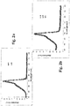
- Fig. 7 demonstrates reverse energy transfer from an excited QD to the J-aggregate. The results are obtained by exciting QD and transferring energy to the J-aggregate of Myl-2. Fig. 7 shows that energy transfer is improved due to confinement in mesopores.
- Fig. 7a shows experimental emission spectra. Spectrum A displays the emission of the J-aggregate alone showing weak emission with a maximum near 590 nm (excitation at 375 nm). Spectrum B shows that the QD alone strongly emits near 550 nm, but very weakly near 590 nm. Comparison between spectrum C (QD and J-aggregate together) and spectrum A (J-aggregate alone) demonstrates energy transfer from the QD to the J-aggregate.
- J-aggregate emission near 590 nm increases by a factor of 2.5 - 3 (several experiments) due to energy transfer from the QD, while the emission of the QD near 550 nm is quenched by 14% due to energy transfer (B compared with C).
- Energy transfer is further illustrated in the excitation spectra of Fig. 7b (emission 590 nm), where the excitation spectrum B (J-aggregate and QD) vs. spectrum A (J-aggregate alone) show the contribution of the QD in the energy transfer process.
- Increase of the J-aggregate fluorescence emission when exciting in the range 460 to 550 nm is attributed to enhanced absorption of light by the QD.
- the forthcoming example describes the preparation of assembly with QD of gold and J-aggregates of Myl-1 in pores of metal oxide nanoparticle coatings (SiO 2 and AIOOH type 1, Fig. 4 ).
- Dried coatings containing the J-aggregate of Myl-1 were functionalized with a few drops of an aqueous solution of commercially available gold QD (concentration of 3.40 10 13 particles/mL in water) rinsed and dried before spectroscopic measurements.
- Gold QD were purchased from Sigma-Aldrich. QD-diameters of 5 nm were used.
- Gold nanoparticle concentrations in aqueous solutions were varied between 6.8 10 12 particles/mL and 6.8 10 13 particles/mL. The same quenching rate, in the range of 80% to 90%, was obtained.
- FIG 8 shows the emission spectra (excitation 510 nm) of the J-aggregate of Myl-1 with and without commercial gold-QD solutions on SiO 2 .
- the dashed-line spectrum represents the fluorescence intensity of J-aggregate alone in SiO 2 mesoporous coatings.
- the solid-line spectrum represents the fluorescence intensity of the J-aggregate in presence of the gold-QD in SiO 2 mesoporous coatings.
Landscapes
- Chemical & Material Sciences (AREA)
- Engineering & Computer Science (AREA)
- Nanotechnology (AREA)
- Crystallography & Structural Chemistry (AREA)
- Physics & Mathematics (AREA)
- Manufacturing & Machinery (AREA)
- General Physics & Mathematics (AREA)
- Condensed Matter Physics & Semiconductors (AREA)
- Materials Engineering (AREA)
- Composite Materials (AREA)
- Health & Medical Sciences (AREA)
- Life Sciences & Earth Sciences (AREA)
- General Health & Medical Sciences (AREA)
- Molecular Biology (AREA)
- Luminescent Compositions (AREA)
- Optics & Photonics (AREA)
- Investigating, Analyzing Materials By Fluorescence Or Luminescence (AREA)
Description
- The present invention relates to the field of nanotechnology. More specifically, it concerns an assembly made up of:
- a support comprising a mesoporous coating whereof the pores have an average diameter of 1-100 nm so as to enable molecules from the family of cyanines to penetrate them, and
- a layer of molecules from the family of cyanines and organized into J-aggregates within the pores of the coating.
- The assembly of the present invention is defined in
claim 1. - J-aggregates are self-arrangements of cyanine molecules which form very ordered assemblies whereof the organizations are of the crystalline type. A description of J-aggregates and their properties can be found in the article by H. Kuhn et al. in a book entitled "J-aggregates" by T. Kobayashi, ISBN 981-02-2737-X. Due to the nearly flawless organization of J-aggregates, they have remarkable properties. Mainly, the electro-optical properties of J-aggregates result from exceptional interactions between the transition dipole moments of the dyes, creating extended exciton states after exposure to light. Characteristics for J-aggregates are a narrow excitonic absorption band and resonance fluorescence. Connected to that are many other exceptional properties of J-aggregates, such as super-radiant emission, high non-linear susceptibilities, efficient energy migration and superquenching. Applications in sensing, light harvesting, light-emitting diodes and non-linear optics can all greatly benefit from the unique properties of J-aggregates. Device driven research on J-aggregates is further highly motivated by the fact that a counterpart on the side of inorganic semiconductors does not exist.
-
- Promoting energy transfer through J-aggregates is the purpose of the assembly of the present invention. Actually, an exciton spread in a J-aggregates can be caught by a suitable energy acceptor having a spectral overlap between its absorption spectrum and the emission spectrum of the J-aggregates. The energy acceptor should be arranged in the vicinity of the J-aggregates.
- Suitable energy acceptors for excited J-aggregates can be dye molecules, semiconductor or metal based nanoparticles. In a preferred application, colloidal semiconductor quantum dots (QD) can be used as energy acceptors. One can also consider the opposite situation where the QD is used as donor and J-aggregates as acceptor.
- A quantum dot is a portion of matter (in general semiconductor based) whose excitons are confined in all three spatial dimensions. Consequently, such materials have electronic properties intermediate between those of bulk semiconductors and those of discrete molecules. Nanoparticles made of metals may also be labelled quantum dots if they are small enough (typically
sub 10 nm) so that quantization of electronic energy levels occurs. Some experiments known in the art have shown that metal based nanoparticles present such properties and one can expect that transition metals may also present such QD properties. In addition, a new type of cadmium free quantum dots made from rare earth doped oxide materials and showing bright emissions and similar optical properties to those of other semiconducting quantum dots have been developed because of legislation restricting the use of heavy metals (typically Cd, Hg, Pb). Thus, in the present disclosure, the term QD will include semi-conducting QD, metal based particles the dimension of which enabling them to present QD properties, and rare earth doped oxide based nanoparticles. As non-limiting example, one can cite the following commercially available semi-conducting species: semi-conductor based QD will include CdS, CdSe, ZnS, CdTe, InAs, InP, CdSeS, ZnO, Ag halides and mixed systems containing one or several of these semiconductors. Metal based QD will include Cu, Ag, Au, Ni, Pd, Pt, Co, Cr, Ru, Fe. Oxide based QD will preferably include BaTiO3, and YVO4 doped with rare earth elements. - In various papers by Bulovic et al. (publ. 2009 (J-aggregates only in water), 2010 (J-aggregates also in films) and 2011 (J-aggregates in films),
WO2009026105 andWO2011146299 patent applications, energy transfer processes between J-aggregates and quantum dots are described in detail. - It should be understood that the distance between J-aggregates and quantum dots is an important criterion to obtain an energy transfer between these species. Typically, this distance should be comprised between 0.1 and 10 nm. Correct distances for energy transfer have been adjusted by the Langmuir-Blodgett (LB) technique (J. Imaging Sci. 1988, 32(2), 64). A patent by
Tischler et al. (US7799422, 2006 ), Walker et al. (Nano Letters 2010, 10(10), 3995) and Agranovich et al. (arXiv preprint, ArXiv:0801.3794, 2008) show that optimum distances for energy transfer between J-aggregates and semiconductor QD can be adjusted using layer-by-layer deposition (LBL) instead of LB-layers. Both methods of distance adjustment, LB and LBL, are not feasible for industrial manufacturing of devices containing highly perfect J-aggregates. - In document
WO2009026105, Bulovic et al. propose a new method to adjust the distance between J-aggregates and quantum dots by electrostatic interactions, i.e. by electrostatic conjugation of cyanine J-aggregates at the surface of a quantum dot after ligand exchange reaction. After deposition of this molecular construct, the resulting quantum dot/J-aggregate films exhibit energy transfer from J-aggregates to quantum dots. In this case the relatively high efficiency of this energy transfer is explained by the close conjugation of quantum dots and coherently coupled dyes in contrast to previous work where the energy transfer efficiency was limited by using polyelectrolyte layers separating the donors and acceptors. Another method to adjust the distance between J-aggregates and quantum dots by electrostatic interactions has been described by Savateeva et al. (Physics, Chemistry, and Applications of nanostructures, 2011, 173; J. Mater. Chem. 2012, 22, 10816) without having to synthesize constructs between cyanine monomers and QD in aqueous solutions. Films containing these QD-J-aggregates hybrid systems were not described. - Such methods present several drawbacks. It can only be achieved by relatively complex synthesis of "QD J-aggregates constructs". Films can only be manufactured for down conversion, i.e. by exciting J-aggregates and emitting in QD.
- The present invention aims to propose a new method making it possible to obtain rather simply energy transfer between J-aggregates and energy donors or acceptors.
- More particularly, the invention concerns an assembly made up of
- a support comprising a mesoporous coating whereof the pores have an average diameter 1-100 nm so as to enable molecules from the family of cyanines to diffuse into the mesoporous coating and to penetrate into the pores, molecules from the family of cyanines and organized into J-aggregates at least within the pores of the mesoporous coating.
- Advantageously, QD are chosen so as to be able to act as energy acceptors or donors for the J-aggregates.
- Advantageously, QD are chosen so as to be able to act as electron acceptors or donors.
- In a preferred embodiment, said pores have an average diameter dimensioned so as to enable macromolecules with dendritic architecture to penetrate them. The assembly is also made up of such macromolecules forming a functionalized layer at least in said pores and said layer of molecules from the family of cyanines interact with the macromolecules with dendritic architecture to form J-aggregates.
- The invention will be better understood upon reading the description which follows, done in reference to the appended drawings in which:
-
figure 1 represents schematically the configuration of an assembly made up according to a preferred embodiment of the invention, -
figure 2 proposes absorption spectra of J-aggregates with and without QD (figure 2a ), and with QD after different duration of storage (figure 2b ), -
figure 3 illustrates energy transfer between J-aggregates and QD on a reference glass substrate by using the J-aggregate as a donor and the QD as acceptors, -
figure 4 shows a table disclosing some possible metal oxides able to form the mesoporous substrate and some of their properties, -
figure 5 proposes spectra illustrating excitation of J-aggregates of Myline-1 as donors and energy transfer between J-aggregates and QD acceptors in a porous film, -
figure 6 (emission spectra) demonstrates the stability of QD in an assembly made up according to a preferred embodiment of the invention, -
figure 7 (emission and excitation spectra) illustrates a case where a QD with emission near 540 nm was excited at 375 nm and energy transfer occurred to J-aggregates of Myline-2 used as energy acceptors in films. -
Figure 8 illustrates the energy transfer from excited J-aggregates of Myl-1 to 5 nm Gold QD (3.40 1013 particles/mL) in mesoporous coatings of SiO2. - One example of a method for producing a particular J-aggregate/Quantum Dot (QD) device will be described in detail below as a non-limiting illustration of the invention.
- As one will understand, the method essentially consists of preparing near room temperature a nanoparticular metal-oxide coating on a substrate chosen among organic, metallic or ceramic substrates so as to form a mesoporous coating. The dimensions of the pores are typically ranged between 1 and 100 nm, preferably between 2 and 50 nm.
- Then dendritic architecture molecules are adsorbed along the mesoporous coating walls including the mesopores walls of the metal-oxide coating and thus define a dendrimer support. Cyanine molecules are subsequently self-assembled into supramolecular J-aggregates on this dendrimer support at least within the pores. Commercially available QD are then incorporated into the pores containing the J-aggregates from aqueous solutions. One or more QD can be introduced within one pore.
- Even if such method is preferred, one can also consider forming J-aggregates directly within pores of a mesoporous coating without any intermediate dendritic architecture based functionalized layer. As a non-limiting example, it has been demonstrated by Nüesch et al. (ref. J. Am. Chem. Soc. 1996, 118, 5420-5431) that hydroxylated and salt-impregnated mesoporous metal oxide films can be used for templating the aggregation processes. The authors have indeed described a method to form aggregates by controlling the texture of the porous films, their surface energy and the atmospheric conditions such as the presence of solvent or the humidity rate. This method can therefore be considered in this invention for the fabrication of mesoporous coating containing dye J-aggregates within their porous network, although J-aggregates obtained here are much less perfect and stable than by using macromolecules with dendritic architectures.
- In addition, even if the methods described above have been demonstrated for mesoporous metal oxide coatings made from aqueous solutions, one can also consider forming J-aggregates within pores of a mesoporous organic matrix with, or without any intermediate dendritic architecture based functionalized layer. As a non-limiting example, Heier et al. (ref Langmuir, 2010, 26(6), 3955 and Phys. Chem. Chem. Phys. 2011, 13, 15714) recently described the synthesis of cyanine aggregates in nanostructured organic films fabricated by means of phase separation processes. Such methods as well as the use of mesoporous polymeric templates made by polymer demixing, block-copolymer phase separation or by replication as already described in the literature (ref. Popa et al. ; Walheim et al. Science, 1999, 283, 520; R. Pugin et al. Journal of Photopolymer Science and Technology, 2009, Vol. 22, 2, 223) can therefore be considered in this application for the fabrication of mesoporous organic coatings containing cyanine dye aggregates within their porous network.
- The preparation of mesoporous nanoparticular coatings with various metal oxides on a large variety of substrate and the subsequent functionalization with J-aggregates have been described in document
EP2028236 hereby incorporated by reference. For SiO2 coatings, one can refer to the applicationUS2007196596 also incorporated by reference. It should be noticed that cyanines intended to form the J-aggregates diffuse into the mesoporous coating and penetrate into the mesopores. - One can use the different dyes defined in the article of D.M. Sturmer published in the book "Chemistry of heterocyclic compounds: special topics", ), and including structure examples which are given respectively in
Figs. 2a and 2b ,3 , 9, 10 and 14, ofEP1788036 hereby incorporated by reference. - One can cite, as preferred cyanines to form J-aggregates [5, 5'-diphenyl-dibenzoxazolo N, N'-propylsulfonate]-9 ethyl trimethine cyanine, called Myline 1 (Myl-1), and 5,5',6,6'-
tetrachloro dibenzimidalolo 2,2'-butylsulfonate 9,9'-N-diethyl trimethine cyanine, called Myline 2 (Myl-2) (see structures in patentEP1788936 fig. 4 and 9 respectively). Myl-1 and Myl-2 were synthesized by ILFORD IMAGING Switzerland. More generally, cyanines, mero-cyanines, squaraines and their derivatives, are capable of self-assembly in order to form J-aggregates. - Dried coatings containing the J-aggregates (as described above) were functionalized with an aqueous solution of commercially available QD, rinsed and dried before spectroscopic measurements. For instance, QD can be supplied by Cytodiagnostics, proposing core-shell structured colloidal QD, the semiconducting core being composed of different Cd or Zn sulphides and selenides, and the external shell made of a stabilising organic layer presenting different chemical groups (e.g. OH or NH2, referred below as QD-OH and QD-NH2 respectively). The total diameter is approximately 10 nm. Concentrations of QD solutions were varied between 1 to 25 mg per mL as shown in results proposed thereafter.
- The configuration obtained is schematically illustrated in
figure 1 . In a pore of a mesoporous nanoparticular metal-oxide coating, macromolecules with dendritic architecture are adsorbed on the internal walls of the pores. Said pores have an average diameter dimensioned so as to enable macromolecules with dendritic architecture to penetrate them. The macromolecules with dendritic architecture form a functionalized layer at least in said pores. - Then, a layer of molecules from the family of cyanines interacting with the macromolecules with dendritic architecture is organized into J-aggregates within the pores of the metal oxide coating.
- One or more QD may also be accommodated within the same pores as those containing the J-aggregates and, as it will be explained thereafter, may interact and undergo energy transfer with J-aggregates.
- It has been surprising to observe that QD did not affect the J-aggregate stability.
Figure 2 represents absorption spectra of J-aggregate of Myl-1. As previously described in applicationEP2028236 , high quality J-aggregates are formed in the pores as proved by the sharp absorption peaks. - On
Figure 2a , one can compare absorption spectra with (B) and without QD (A). Said spectra are identical within experimental errors. Onfigure 2b one can compare absorption spectra containing J-aggregates of Myl-1 together with QD after storage in the absence of light during up to 22 days in air.Figs. 2b (A, B, C) show Absorption spectra after 0, 6 and 22 days, respectively. This shows that the presence of the QD has no influence on the long-term stability of the J-aggregates. - As a reference to prove the advantages of mesoporous substrates, it has been proposed experiments on a planar substrate, where the vicinity of the species is limited and obtained by successive layer by layer depositions.
- A monolayer of a highly perfect Myl-1 J-aggregate on a PAMAM G4 support deposited on a glass substrate has been prepared. One can refer to
EP1788036 for experimental details about this preparation. After rinsing and drying, a 5 times diluted commercial aqueous QD solution is applied by spin-coating onto the dried J-aggregate layer. Spectral measurements shown inFigure 3 were carried out after rinsing and drying. - On the emission spectra of
figure 3a are represented, for an excitation at 510 nm, a spectrum A for Myl-1 J-aggregates on a glass substrate, a spectrum B for QD diluted 5 times on a glass substrate, a spectrum C for Myl-1 J-aggregates and QD diluted 5 times on a glass substrate. In order to remove spectral influences of remaining monomers and dimers of the cyanine, these spectra are filtered by deconvolution infigure 3b , where spectra B and A are for QD alone and J-aggregates of Myl-1 alone, respectively. Spectrum C1 shows the partial quenching of Myl-1 J-aggregates by the presence of QD, and spectrum C2 shows enhanced emission of the QD after energy transfer. Results obtained are 50% J-aggregate fluorescence quenching and enhancement of the QD signal by a factor of 2.5, to be compared to 100% J-aggregate fluorescence quenching and enhancement of the QD signal by a factor of 2.5 in Bulovic's method cited in prior art. - Such experiments demonstrate that energy transfer may occur between commercially available QD and J-aggregates, even if the enhancement obtained here is only similar to that obtained by Bulovic's method.
- Above proposed experiments have been extended to mesoporous substrates in order to evaluate the potential influence of confinement on energy transfer efficiency between QD and J-aggregates.
- Different parameters have been tested.
Figure 4 represents several materials used to form the mesoporous substrate. The table indicates the shape and the diameter of agglomerated particles and in parenthesis, the diameter of elementary particles. AIOOH Types 1 and 2 were purchased from SASOL Ltd. SiO2 was purchased from CABOT Ltd. The table also indicates the volume and mean diameter of pores measured with the nitrogen adsorption method. Materials should be chosen so as to enable molecules from the family of cyanines intended to form the J-aggregates and QD to penetrate them. As taught byEP2028236 , mesoporous coatings can be realized in a material chosen among AIOOH, TiO2, ITO, SiO2, γQ-Al2O3, ZrO2, SnO2, ZnO, Ta2O5, mixture of them or with a base of doped conductor oxide nanoparticles. The mesoporous coatings can also be made of organic matrix, as described in references mentioned in paragraph [0021] above. - The mean diameter of pores of the mesoporous layer should be large enough to enable encapsulation of the selected QD. QD are inserted into the pores of the mesoporous substrate by using similar methods as those proposed for glass substrate.
- The addition of the QD within the mesoporous coating should not lead to a modification of the absorption spectrum of the J-aggregates that would result from the disassembling of the J-aggregates. QD should also not be destabilized (i.e. not aggregated) by J-aggregates or by the chemical compounds present in the assembly according to the invention. It should also present an overlap between the emission spectrum of the donor with the absorption spectrum of the acceptor to make the energy transfer possible.
- One can also consider having electron/hole transfer that would require an overlap of the electronic states (between donor and acceptor) that enables electron transfer. As a matter of comparison with energy transfer, it is well known that the distance between the QD and the donor/acceptor for electron transfer should be much shorter, typically below 2 nm (see for example Barbara et al., J. Phys. Chem., 1996, 100, 13148-13168).
- If a functionalized layer of macromolecules of dendritic architecture is used so as to contribute to the J-aggregate formation, one will refer to the documents
EP1788036 andEP2028236 to obtain information regarding suitable dendrimers. Experiments have been conducted with PAMAM G4. However, even if this solution may be preferred because it offers a very efficient and cost effective solution to obtain J-aggregates within pores, one could consider methods obtaining such J-aggregates without any intermediate dendrimer layer, as mentioned above. - One will now refer to
figures 5-7 and to the table hereafter.Figure 5 shows the emission spectra of Myl-1 after deconvolution with and without commercial QD solutions diluted 30 times on SiO2. Spectrum A represents fluorescence intensity of J-aggregate alone in SiO2 mesoporous coatings. Spectrum B represents the fluorescence intensity of the QD alone (diluted 30 times in water) in SiO2 mesoporous coatings. Spectrum C1 represents the fluorescence intensity of the J-aggregate in presence of the QD (diluted 30 times in water) in SiO2 mesoporous coatings. Spectrum C2 represents the fluorescence intensity of QD diluted 30 times in water in presence of the J-aggregate in SiO2 mesoporous coating. One obtains 58% quenching of the intensity of the J-aggregate emission peak (spectrum C1) and an enhancement of 9 times of the intensity of the QD fluorescence peak (spectrum C2). This illustrates down-conversion and energy transfer between QD as acceptor and J-aggregate as donor. - The following table illustrates different results obtained with different cyanines and QD for down conversion using the J-aggregates as donors and the QD as acceptors after deconvolution. In all cases, emission as well as excitation spectra confirmed the energy transfer.
Metal oxide coating QD type Cyanine Dilution rate of QD solution QD/J-aggregate fluorescence intensity ratio Quenching rate of J-aggregate fluorescence Enhancement rate of QD fluorescence by energy transfer SiO2 QD-OH Myl-1 5 0.4 0.55 1 SiO2 QD-OH Myl-1 30 0.012 0.58 9 SiO2 QD-NH2 Myl-1 30 0.001 0.60 20 AIOOH Type 2QD-OH Myl-1 1 0.18 0.43 1 AIOOH Type 2QD-OH Myl-1 5 0.3 0.50 1 AIOOH Type 2QD-OH Myl-1 30 0.0053 0.50 15 AIOOH Type 1QD-OH Myl-1 1 0.31 0.43 1 AIOOH Type 1QD-OH Myl-1 5 0.32 0.46 1 AIOOH Type 1QD-OH Myl-1 30 0.012 0.59 20 Flat glass QD-OH Myl-1 5 0.17 0.50 2.5 SiO2 QD-OH Myl-2 30 0.04 0.41 6-7 - One can observe that no enhancement is obtained for as received or only 5 times diluted QD solutions, while the J-aggregate fluorescence is always partially quenched. This can be explained by clustering effects of QD within the pores that inhibit energy transfer from QD to J-aggregates.
- For more diluted QD solutions, one obtains enhancement comprised between 9 and 20 times for only 50% of fluorescence quenching of the J-aggregates, to be compared with 2.5 times for 50% on planar glass substrate and 2.5 times for 100% quenching by Bulovic.
- According to the invention, extraordinary strong enhancement obtained with diluted QD in mesoporous coatings is due to confinement in pores that enables a "template effect" to have QD at an appropriate distance from the J-aggregates, and to very favourable arrangement of QD (no clustering) in these pores compared to planar substrates. Here, the QD alone contributes very little to emission.
- In the smallest pores (
AIOOH Type - Best results are obtained if the fluorescence intensity of the QD/J-aggregate is not too high (≤ 0.2), as otherwise we have recombination effects due to QD-clustering after energy transfer. Such effects lead to enhancement losses of QD emission after energy transfer. QD should also be diluted enough to avoid clustering effects within the pores.
- It should also be noted that light stability of J-aggregates in presence of QD within a same mesopore is much higher (min. by a factor of 100) for Myl-1 J-aggregates, than without QD. This also proves energy transfer between J-aggregates and QD occurs and increases the stability of the J-aggregates.
-
Fig. 6 shows emission spectra for QD (emission near 590 nm) in SiO2 (films) during storage in air and absence of actinic light near room temperature.Figs. 6 A-D show spectra after 0, 2, 6 and 22 days respectively, showing that the fluorescence emission of the QD varies little and rather improves somewhat with storage time. -
Fig. 7 demonstrates reverse energy transfer from an excited QD to the J-aggregate. The results are obtained by exciting QD and transferring energy to the J-aggregate of Myl-2.Fig. 7 shows that energy transfer is improved due to confinement in mesopores.Fig. 7a shows experimental emission spectra. Spectrum A displays the emission of the J-aggregate alone showing weak emission with a maximum near 590 nm (excitation at 375 nm). Spectrum B shows that the QD alone strongly emits near 550 nm, but very weakly near 590 nm. Comparison between spectrum C (QD and J-aggregate together) and spectrum A (J-aggregate alone) demonstrates energy transfer from the QD to the J-aggregate. Here, J-aggregate emission near 590 nm increases by a factor of 2.5 - 3 (several experiments) due to energy transfer from the QD, while the emission of the QD near 550 nm is quenched by 14% due to energy transfer (B compared with C). Energy transfer is further illustrated in the excitation spectra ofFig. 7b (emission 590 nm), where the excitation spectrum B (J-aggregate and QD) vs. spectrum A (J-aggregate alone) show the contribution of the QD in the energy transfer process. Increase of the J-aggregate fluorescence emission when exciting in therange 460 to 550 nm is attributed to enhanced absorption of light by the QD.Fig. 7c shows absorption spectra of J-aggregate alone (Spectrum A) and J-aggregate + QD (Spectrum B). The contribution of the QD to the absorption spectrum is a less decreasing curve approximated by the dashed line, while the absorption maximum and the FWHM of the J-aggregate remain unchanged. The efficiency of this process is improved in our films as compared to aqueous solutions (experiments Bulovic et al., cited above), where an enhancement factor of only 5 was observed for 100% fluorescence quenching of the QD instead of 3 but for only 14% quenching in our experiments. - It is therefore proposed a very efficient method enabling the control of the distance between QD and J-aggregates, so as to promote energy/electron transfers.
- The forthcoming example describes the preparation of assembly with QD of gold and J-aggregates of Myl-1 in pores of metal oxide nanoparticle coatings (SiO2 and
AIOOH type 1,Fig. 4 ). Dried coatings containing the J-aggregate of Myl-1 were functionalized with a few drops of an aqueous solution of commercially available gold QD (concentration of 3.40 1013 particles/mL in water) rinsed and dried before spectroscopic measurements. Gold QD were purchased from Sigma-Aldrich. QD-diameters of 5 nm were used. Gold nanoparticle concentrations in aqueous solutions were varied between 6.8 1012 particles/mL and 6.8 1013 particles/mL. The same quenching rate, in the range of 80% to 90%, was obtained. - One will now refer to the
figure 8 . It shows the emission spectra (excitation 510 nm) of the J-aggregate of Myl-1 with and without commercial gold-QD solutions on SiO2. The dashed-line spectrum represents the fluorescence intensity of J-aggregate alone in SiO2 mesoporous coatings. The solid-line spectrum represents the fluorescence intensity of the J-aggregate in presence of the gold-QD in SiO2 mesoporous coatings. One obtains 80% quenching of the intensity of the J-aggregate emission peak, illustrating energy transfer from the excited J-aggregate Donor Myl-1 to the gold QD acceptor. - In the case where
AIOOH type 1 coatings were used instead of SiO2 coatings (Fig. 4 ), only 25% fluorescence quenching of the J-aggregate was measured instead of 80%. This is due to the smaller mesopore diameter (20 nm) in AIOOH instead of 30 nm in SiO2, thus allowing the accomodation of a smaller amount of gold QD in a mesopore ofAIOOH type 1 which decreases the efficiency of energy transfer. Absorption spectra (not shown here) of SiO2-coatings with Au-QD alone and Au-QD + J-aggregates have revealed that both partners are present in SiO2 coatings. The presence of Au-QD does not affect J-aggregate spectra, as their absorbance (maximum near 526 nm) is much lower than that of the J-aggregates. - One can also consider inserting in the pores of the mesoporous substrate some other species (organic molecules like dyes) which, thanks to the confinement provided by the pore dimensions, may be able to act as energy or electron donors/acceptors for the J-aggregates located in the same pore.
Claims (14)
- An assembly made up of- a support comprising a mesoporous coating whereof the pores have an average diameter of 1-100 nm as to enable molecules from the family of cyanines to diffuse into the mesoporous coating,- molecules from the family of cyanines organized into J-aggregates at least within the pores of the mesoporous coating,characterized in that said assembly moreover comprises Quantum Dots located within the same pores as those containing the J-aggregates, said Quantum Dots maintaining J-aggregates structure.
- Assembly according to claim 1, characterized in that the distance between J-aggregates and quantum dots being preferably comprised between 0.1 nm and 10nm.
- Assembly according to claim 1 or claim 2, wherein said pores comprise macromolecules with dendritic architecture forming a functionalized layer at least in said pores.
- Assembly according to one of claim 1 to 3, wherein said Quantum Dots and the J-aggregates present an overlap between the emission spectrum of the donor with the absorption spectrum of the acceptor to enable energy transfer.
- Assembly according to one of claim 1 to 3, wherein said Quantum Dots and the J-aggregates present an overlap of the electronic states between the donor and the acceptor to enable electron transfer.
- Assembly according to one of the preceding claims, wherein said Quantum Dot measures less than 15 nm, preferably less than 10 nm, at least in one dimension of space.
- Assembly according to one of the preceding claims, wherein said Quantum Dots are semi-conducting nanoparticular species among CdS, CdSe, ZnS, CdTe, InAs, InP, CdSeS, ZnO, Ag halides and mixed systems containing one or several of these semiconductors, or
wherein said Quantum Dots are said metallic nanoparticular species among Cu, Ag, Au, Ni, Pd, Pt, Co, Cr, Ru, Fe, or
wherein said Quantum Dots include BaTiO3, and YVO4 doped with rare earth elements. - Assembly according to any of the preceding claims, wherein said macromolecule with dendritic architecture is a dendrimer molecule.
- Assembly according to any of the preceding claims said support comprises a mesoporous metal oxide coating.
- Assembly according to claim 9, wherein said mesoporous coating is realized in a material chosen among AIOOH, TiO2, ITO, SiO2, γ-Al2O3, ZrO2, SnO2, ZnO, Ta2O5, or a mixture of these materials or doped conductor oxide nanoparticles.
- Assembly according to any of the preceding claims, wherein the average diameter of the pores of the mesoporous coating is comprised between 2 and 50 nm.
- A method for producing an assembly according to one of the preceding claims, comprising the following steps:i. obtaining a support comprising a mesoporous coating whereof the pores have an average diameter of 1-100 nm so as to enable molecules from the family of cyanines and Quantum Dots to penetrate them,ii. forming a layer of J-aggregates of cyanines molecules within the pores of the support,iii. introducing Quantum Dots within the same pores as those containing the J-aggregates, said Quantum Dots maintaining J-aggregates structure.
- Method according to claim 12 comprising furthermore the steps of:iv. depositing a solution of macromolecules with dendritic architecture on the support, so as to functionalize the pores, the layer of J-aggregates being formed on the layer of macromolecules with dendritic architecture.
- Method according to one of claims 12 and 13, wherein Quantum Dots are introduced into pores in a diluted solution so as to avoid clustering effects within the pores.
Priority Applications (1)
| Application Number | Priority Date | Filing Date | Title |
|---|---|---|---|
| EP13176195.9A EP2708492B1 (en) | 2012-07-13 | 2013-07-11 | Mesoporous layer comprising J-aggregates and production method |
Applications Claiming Priority (2)
| Application Number | Priority Date | Filing Date | Title |
|---|---|---|---|
| EP20120176306 EP2684839A1 (en) | 2012-07-13 | 2012-07-13 | Mesoporous coating comprising j-aggregates |
| EP13176195.9A EP2708492B1 (en) | 2012-07-13 | 2013-07-11 | Mesoporous layer comprising J-aggregates and production method |
Publications (2)
| Publication Number | Publication Date |
|---|---|
| EP2708492A1 EP2708492A1 (en) | 2014-03-19 |
| EP2708492B1 true EP2708492B1 (en) | 2017-11-29 |
Family
ID=48746406
Family Applications (2)
| Application Number | Title | Priority Date | Filing Date |
|---|---|---|---|
| EP20120176306 Withdrawn EP2684839A1 (en) | 2012-07-13 | 2012-07-13 | Mesoporous coating comprising j-aggregates |
| EP13176195.9A Active EP2708492B1 (en) | 2012-07-13 | 2013-07-11 | Mesoporous layer comprising J-aggregates and production method |
Family Applications Before (1)
| Application Number | Title | Priority Date | Filing Date |
|---|---|---|---|
| EP20120176306 Withdrawn EP2684839A1 (en) | 2012-07-13 | 2012-07-13 | Mesoporous coating comprising j-aggregates |
Country Status (2)
| Country | Link |
|---|---|
| US (1) | US9238582B2 (en) |
| EP (2) | EP2684839A1 (en) |
Cited By (1)
| Publication number | Priority date | Publication date | Assignee | Title |
|---|---|---|---|---|
| WO2020108069A1 (en) * | 2018-11-28 | 2020-06-04 | Tcl科技集团股份有限公司 | Nano metal oxide, preparation method therefor, and quantum dot light-emitting diode |
Families Citing this family (3)
| Publication number | Priority date | Publication date | Assignee | Title |
|---|---|---|---|---|
| CN104932136B (en) * | 2015-07-01 | 2018-01-26 | 合肥鑫晟光电科技有限公司 | Color membrane substrates and preparation method thereof, display panel and display device |
| KR20180022042A (en) * | 2016-08-23 | 2018-03-06 | 삼성전자주식회사 | Quantum dot composition, preparation mehtod therof and device using the composition |
| CN115608382B (en) * | 2022-10-24 | 2024-08-06 | 上海科技大学 | Semiconductor nanocrystalline aggregate and preparation method and application thereof |
Family Cites Families (8)
| Publication number | Priority date | Publication date | Assignee | Title |
|---|---|---|---|---|
| WO2006020920A2 (en) | 2003-01-29 | 2006-02-23 | Medtronic, Inc. | Catheter apparatus for treatment of heart arrhythmia |
| JP4846720B2 (en) | 2004-08-12 | 2011-12-28 | メドトロニック,インコーポレイテッド | Catheter apparatus for treating cardiac arrhythmia |
| US7799422B2 (en) | 2004-11-03 | 2010-09-21 | Massachusetts Institute Of Technology | Absorbing film |
| CH703675B1 (en) | 2005-11-16 | 2012-03-15 | Suisse Electronique Microtech | Process for producing J aggregates |
| ATE451246T1 (en) | 2006-02-21 | 2009-12-15 | Ilford Imaging Ch Gmbh | RECORDING MATERIAL FOR INKJET PRINTING |
| EP2188825B1 (en) | 2007-08-17 | 2015-01-07 | Massachusetts Institute of Technology | Light emitting material |
| DE602007008404D1 (en) | 2007-08-23 | 2010-09-23 | Suisse Electronique Microtech | Composition comprising J-aggregates |
| US20110278536A1 (en) | 2010-05-17 | 2011-11-17 | Massachusetts Institute Of Technology | Light emitting material |
-
2012
- 2012-07-13 EP EP20120176306 patent/EP2684839A1/en not_active Withdrawn
-
2013
- 2013-07-11 EP EP13176195.9A patent/EP2708492B1/en active Active
- 2013-07-15 US US13/941,578 patent/US9238582B2/en active Active
Non-Patent Citations (1)
| Title |
|---|
| None * |
Cited By (1)
| Publication number | Priority date | Publication date | Assignee | Title |
|---|---|---|---|---|
| WO2020108069A1 (en) * | 2018-11-28 | 2020-06-04 | Tcl科技集团股份有限公司 | Nano metal oxide, preparation method therefor, and quantum dot light-emitting diode |
Also Published As
| Publication number | Publication date |
|---|---|
| US9238582B2 (en) | 2016-01-19 |
| US20140017485A1 (en) | 2014-01-16 |
| EP2684839A1 (en) | 2014-01-15 |
| EP2708492A1 (en) | 2014-03-19 |
Similar Documents
| Publication | Publication Date | Title |
|---|---|---|
| Sarma et al. | Fabrication of Ag/ZnO heterostructure and the role of surface coverage of ZnO microrods by Ag nanoparticles on the photophysical and photocatalytic properties of the metal-semiconductor system | |
| Kotov | Nanoparticle assemblies and superstructures | |
| Zhao et al. | Low‐dimensional nanomaterials based on small organic molecules: preparation and optoelectronic properties | |
| KR101140309B1 (en) | Electroluminescent device including quantum dot multilayer thin film | |
| Winter et al. | The marriage of terpyridines and inorganic nanoparticles: synthetic aspects, characterization techniques, and potential applications | |
| US20070116627A1 (en) | Carbon nanotube compositions and devices and methods of making thereof | |
| EP2708492B1 (en) | Mesoporous layer comprising J-aggregates and production method | |
| US20110278536A1 (en) | Light emitting material | |
| Ahmed et al. | Size-dependent photodegradation of CdS particles deposited onto TiO 2 mesoporous films by SILAR method | |
| CN107681463B (en) | The polymer laser and preparation method thereof of continuous optical pumping | |
| CN111492036A (en) | Stable INP quantum dot with thick shell cladding and manufacturing method thereof | |
| JP2008534424A (en) | CDTE / GSH core-shell quantum dots | |
| Kim et al. | Enhanced colloidal stability of perovskite quantum dots via split-ligand re-precipitation for efficient bi-functional interlayer in photovoltaic application | |
| KR20160119204A (en) | Method for manufacturing a thin film consisting of a colloidal crystal infiltrated with the luminescent mdmo-ppv polymer made of silica(sio2) spheres, having a face-centered cubic system(fcc) | |
| Steiger et al. | J-aggregation of cyanine dyes by self-assembly | |
| Kumari et al. | Effect of surface passivating ligand on structural and optoelectronic properties of polymer: CdSe quantum dot composites | |
| Valli et al. | Photoresponsive multilayer films by assembling cationic amphiphilic cyclodextrins and anionic porphyrins at the air/water interface | |
| Yamamoto et al. | Synthesis and photoluminescence characterization of dendrimer-encapsulated CdS quantum dots | |
| JP2000126681A (en) | Manufacture of nanoparticle thin film | |
| Mehta et al. | Constraints in post-synthesis ligand exchange for hybrid organic (MEH-PPV)–inorganic (CdSe) nanocomposites | |
| Abdelbar et al. | Photo-induced interaction of thioglycolic acid (TGA)-capped CdTe quantum dots with cyanine dyes | |
| US7132163B1 (en) | Heteroporphyrin nanotubes and composites | |
| Kharkwal et al. | One-pot synthesis of CuInS 2 and CuInS 2/MS (M= Cd, Zn) core–shell luminescent nanocrystals: a low-temperature and low-cost approach | |
| Grevtseva et al. | Photostability of luminescence of Ag2S quantum dots and Ag2S/SiO2 core/shell structures | |
| US7824617B2 (en) | Assembly comprising J aggregates |
Legal Events
| Date | Code | Title | Description |
|---|---|---|---|
| PUAB | Information related to the publication of an a document modified or deleted |
Free format text: ORIGINAL CODE: 0009199EPPU |
|
| PUAI | Public reference made under article 153(3) epc to a published international application that has entered the european phase |
Free format text: ORIGINAL CODE: 0009012 |
|
| PUAI | Public reference made under article 153(3) epc to a published international application that has entered the european phase |
Free format text: ORIGINAL CODE: 0009012 |
|
| AK | Designated contracting states |
Kind code of ref document: A1 Designated state(s): AL AT BE BG CH CY CZ DE DK EE ES FI FR GB GR HR HU IE IS IT LI LT LU LV MC MK MT NL NO PL PT RO RS SE SI SK SM TR |
|
| AX | Request for extension of the european patent |
Extension state: BA ME |
|
| 17P | Request for examination filed |
Effective date: 20140919 |
|
| RBV | Designated contracting states (corrected) |
Designated state(s): AL AT BE BG CH CY CZ DE DK EE ES FI FR GB GR HR HU IE IS IT LI LT LU LV MC MK MT NL NO PL PT RO RS SE SI SK SM TR |
|
| RIC1 | Information provided on ipc code assigned before grant |
Ipc: B82Y 30/00 20110101AFI20170522BHEP Ipc: B82Y 15/00 20110101ALI20170522BHEP Ipc: B82Y 20/00 20110101ALI20170522BHEP Ipc: B82B 3/00 20060101ALI20170522BHEP Ipc: B82B 1/00 20060101ALI20170522BHEP |
|
| GRAP | Despatch of communication of intention to grant a patent |
Free format text: ORIGINAL CODE: EPIDOSNIGR1 |
|
| INTG | Intention to grant announced |
Effective date: 20170707 |
|
| GRAS | Grant fee paid |
Free format text: ORIGINAL CODE: EPIDOSNIGR3 |
|
| GRAA | (expected) grant |
Free format text: ORIGINAL CODE: 0009210 |
|
| AK | Designated contracting states |
Kind code of ref document: B1 Designated state(s): AL AT BE BG CH CY CZ DE DK EE ES FI FR GB GR HR HU IE IS IT LI LT LU LV MC MK MT NL NO PL PT RO RS SE SI SK SM TR |
|
| REG | Reference to a national code |
Ref country code: CH Ref legal event code: EP |
|
| REG | Reference to a national code |
Ref country code: AT Ref legal event code: REF Ref document number: 950195 Country of ref document: AT Kind code of ref document: T Effective date: 20171215 |
|
| REG | Reference to a national code |
Ref country code: IE Ref legal event code: FG4D |
|
| REG | Reference to a national code |
Ref country code: DE Ref legal event code: R096 Ref document number: 602013030023 Country of ref document: DE |
|
| REG | Reference to a national code |
Ref country code: CH Ref legal event code: NV Representative=s name: NOVAGRAAF INTERNATIONAL SA, CH |
|
| REG | Reference to a national code |
Ref country code: NL Ref legal event code: MP Effective date: 20171129 |
|
| REG | Reference to a national code |
Ref country code: LT Ref legal event code: MG4D |
|
| REG | Reference to a national code |
Ref country code: AT Ref legal event code: MK05 Ref document number: 950195 Country of ref document: AT Kind code of ref document: T Effective date: 20171129 |
|
| PG25 | Lapsed in a contracting state [announced via postgrant information from national office to epo] |
Ref country code: NO Free format text: LAPSE BECAUSE OF FAILURE TO SUBMIT A TRANSLATION OF THE DESCRIPTION OR TO PAY THE FEE WITHIN THE PRESCRIBED TIME-LIMIT Effective date: 20180228 Ref country code: LT Free format text: LAPSE BECAUSE OF FAILURE TO SUBMIT A TRANSLATION OF THE DESCRIPTION OR TO PAY THE FEE WITHIN THE PRESCRIBED TIME-LIMIT Effective date: 20171129 Ref country code: SE Free format text: LAPSE BECAUSE OF FAILURE TO SUBMIT A TRANSLATION OF THE DESCRIPTION OR TO PAY THE FEE WITHIN THE PRESCRIBED TIME-LIMIT Effective date: 20171129 Ref country code: ES Free format text: LAPSE BECAUSE OF FAILURE TO SUBMIT A TRANSLATION OF THE DESCRIPTION OR TO PAY THE FEE WITHIN THE PRESCRIBED TIME-LIMIT Effective date: 20171129 Ref country code: FI Free format text: LAPSE BECAUSE OF FAILURE TO SUBMIT A TRANSLATION OF THE DESCRIPTION OR TO PAY THE FEE WITHIN THE PRESCRIBED TIME-LIMIT Effective date: 20171129 |
|
| PG25 | Lapsed in a contracting state [announced via postgrant information from national office to epo] |
Ref country code: HR Free format text: LAPSE BECAUSE OF FAILURE TO SUBMIT A TRANSLATION OF THE DESCRIPTION OR TO PAY THE FEE WITHIN THE PRESCRIBED TIME-LIMIT Effective date: 20171129 Ref country code: BG Free format text: LAPSE BECAUSE OF FAILURE TO SUBMIT A TRANSLATION OF THE DESCRIPTION OR TO PAY THE FEE WITHIN THE PRESCRIBED TIME-LIMIT Effective date: 20180228 Ref country code: GR Free format text: LAPSE BECAUSE OF FAILURE TO SUBMIT A TRANSLATION OF THE DESCRIPTION OR TO PAY THE FEE WITHIN THE PRESCRIBED TIME-LIMIT Effective date: 20180301 Ref country code: RS Free format text: LAPSE BECAUSE OF FAILURE TO SUBMIT A TRANSLATION OF THE DESCRIPTION OR TO PAY THE FEE WITHIN THE PRESCRIBED TIME-LIMIT Effective date: 20171129 Ref country code: AT Free format text: LAPSE BECAUSE OF FAILURE TO SUBMIT A TRANSLATION OF THE DESCRIPTION OR TO PAY THE FEE WITHIN THE PRESCRIBED TIME-LIMIT Effective date: 20171129 Ref country code: LV Free format text: LAPSE BECAUSE OF FAILURE TO SUBMIT A TRANSLATION OF THE DESCRIPTION OR TO PAY THE FEE WITHIN THE PRESCRIBED TIME-LIMIT Effective date: 20171129 |
|
| PG25 | Lapsed in a contracting state [announced via postgrant information from national office to epo] |
Ref country code: NL Free format text: LAPSE BECAUSE OF FAILURE TO SUBMIT A TRANSLATION OF THE DESCRIPTION OR TO PAY THE FEE WITHIN THE PRESCRIBED TIME-LIMIT Effective date: 20171129 |
|
| REG | Reference to a national code |
Ref country code: FR Ref legal event code: PLFP Year of fee payment: 6 |
|
| PG25 | Lapsed in a contracting state [announced via postgrant information from national office to epo] |
Ref country code: CY Free format text: LAPSE BECAUSE OF FAILURE TO SUBMIT A TRANSLATION OF THE DESCRIPTION OR TO PAY THE FEE WITHIN THE PRESCRIBED TIME-LIMIT Effective date: 20171129 Ref country code: CZ Free format text: LAPSE BECAUSE OF FAILURE TO SUBMIT A TRANSLATION OF THE DESCRIPTION OR TO PAY THE FEE WITHIN THE PRESCRIBED TIME-LIMIT Effective date: 20171129 Ref country code: EE Free format text: LAPSE BECAUSE OF FAILURE TO SUBMIT A TRANSLATION OF THE DESCRIPTION OR TO PAY THE FEE WITHIN THE PRESCRIBED TIME-LIMIT Effective date: 20171129 Ref country code: DK Free format text: LAPSE BECAUSE OF FAILURE TO SUBMIT A TRANSLATION OF THE DESCRIPTION OR TO PAY THE FEE WITHIN THE PRESCRIBED TIME-LIMIT Effective date: 20171129 Ref country code: SK Free format text: LAPSE BECAUSE OF FAILURE TO SUBMIT A TRANSLATION OF THE DESCRIPTION OR TO PAY THE FEE WITHIN THE PRESCRIBED TIME-LIMIT Effective date: 20171129 |
|
| REG | Reference to a national code |
Ref country code: DE Ref legal event code: R097 Ref document number: 602013030023 Country of ref document: DE |
|
| PG25 | Lapsed in a contracting state [announced via postgrant information from national office to epo] |
Ref country code: SM Free format text: LAPSE BECAUSE OF FAILURE TO SUBMIT A TRANSLATION OF THE DESCRIPTION OR TO PAY THE FEE WITHIN THE PRESCRIBED TIME-LIMIT Effective date: 20171129 Ref country code: PL Free format text: LAPSE BECAUSE OF FAILURE TO SUBMIT A TRANSLATION OF THE DESCRIPTION OR TO PAY THE FEE WITHIN THE PRESCRIBED TIME-LIMIT Effective date: 20171129 Ref country code: IT Free format text: LAPSE BECAUSE OF FAILURE TO SUBMIT A TRANSLATION OF THE DESCRIPTION OR TO PAY THE FEE WITHIN THE PRESCRIBED TIME-LIMIT Effective date: 20171129 Ref country code: RO Free format text: LAPSE BECAUSE OF FAILURE TO SUBMIT A TRANSLATION OF THE DESCRIPTION OR TO PAY THE FEE WITHIN THE PRESCRIBED TIME-LIMIT Effective date: 20171129 |
|
| PLBE | No opposition filed within time limit |
Free format text: ORIGINAL CODE: 0009261 |
|
| STAA | Information on the status of an ep patent application or granted ep patent |
Free format text: STATUS: NO OPPOSITION FILED WITHIN TIME LIMIT |
|
| 26N | No opposition filed |
Effective date: 20180830 |
|
| PG25 | Lapsed in a contracting state [announced via postgrant information from national office to epo] |
Ref country code: SI Free format text: LAPSE BECAUSE OF FAILURE TO SUBMIT A TRANSLATION OF THE DESCRIPTION OR TO PAY THE FEE WITHIN THE PRESCRIBED TIME-LIMIT Effective date: 20171129 |
|
| PG25 | Lapsed in a contracting state [announced via postgrant information from national office to epo] |
Ref country code: LU Free format text: LAPSE BECAUSE OF NON-PAYMENT OF DUE FEES Effective date: 20180711 Ref country code: MC Free format text: LAPSE BECAUSE OF FAILURE TO SUBMIT A TRANSLATION OF THE DESCRIPTION OR TO PAY THE FEE WITHIN THE PRESCRIBED TIME-LIMIT Effective date: 20171129 |
|
| REG | Reference to a national code |
Ref country code: BE Ref legal event code: MM Effective date: 20180731 |
|
| REG | Reference to a national code |
Ref country code: IE Ref legal event code: MM4A |
|
| PG25 | Lapsed in a contracting state [announced via postgrant information from national office to epo] |
Ref country code: IE Free format text: LAPSE BECAUSE OF NON-PAYMENT OF DUE FEES Effective date: 20180711 |
|
| PG25 | Lapsed in a contracting state [announced via postgrant information from national office to epo] |
Ref country code: BE Free format text: LAPSE BECAUSE OF NON-PAYMENT OF DUE FEES Effective date: 20180731 |
|
| PG25 | Lapsed in a contracting state [announced via postgrant information from national office to epo] |
Ref country code: MT Free format text: LAPSE BECAUSE OF NON-PAYMENT OF DUE FEES Effective date: 20180711 |
|
| PG25 | Lapsed in a contracting state [announced via postgrant information from national office to epo] |
Ref country code: TR Free format text: LAPSE BECAUSE OF FAILURE TO SUBMIT A TRANSLATION OF THE DESCRIPTION OR TO PAY THE FEE WITHIN THE PRESCRIBED TIME-LIMIT Effective date: 20171129 |
|
| PG25 | Lapsed in a contracting state [announced via postgrant information from national office to epo] |
Ref country code: HU Free format text: LAPSE BECAUSE OF FAILURE TO SUBMIT A TRANSLATION OF THE DESCRIPTION OR TO PAY THE FEE WITHIN THE PRESCRIBED TIME-LIMIT; INVALID AB INITIO Effective date: 20130711 Ref country code: PT Free format text: LAPSE BECAUSE OF FAILURE TO SUBMIT A TRANSLATION OF THE DESCRIPTION OR TO PAY THE FEE WITHIN THE PRESCRIBED TIME-LIMIT Effective date: 20171129 |
|
| PG25 | Lapsed in a contracting state [announced via postgrant information from national office to epo] |
Ref country code: MK Free format text: LAPSE BECAUSE OF NON-PAYMENT OF DUE FEES Effective date: 20171129 |
|
| PG25 | Lapsed in a contracting state [announced via postgrant information from national office to epo] |
Ref country code: AL Free format text: LAPSE BECAUSE OF FAILURE TO SUBMIT A TRANSLATION OF THE DESCRIPTION OR TO PAY THE FEE WITHIN THE PRESCRIBED TIME-LIMIT Effective date: 20171129 Ref country code: IS Free format text: LAPSE BECAUSE OF FAILURE TO SUBMIT A TRANSLATION OF THE DESCRIPTION OR TO PAY THE FEE WITHIN THE PRESCRIBED TIME-LIMIT Effective date: 20180329 |
|
| PGFP | Annual fee paid to national office [announced via postgrant information from national office to epo] |
Ref country code: GB Payment date: 20230724 Year of fee payment: 11 Ref country code: CH Payment date: 20230801 Year of fee payment: 11 |
|
| PGFP | Annual fee paid to national office [announced via postgrant information from national office to epo] |
Ref country code: FR Payment date: 20230720 Year of fee payment: 11 Ref country code: DE Payment date: 20230720 Year of fee payment: 11 |