EP2708291A2 - Support de sonotrodes - Google Patents
Support de sonotrodes Download PDFInfo
- Publication number
- EP2708291A2 EP2708291A2 EP13183837.7A EP13183837A EP2708291A2 EP 2708291 A2 EP2708291 A2 EP 2708291A2 EP 13183837 A EP13183837 A EP 13183837A EP 2708291 A2 EP2708291 A2 EP 2708291A2
- Authority
- EP
- European Patent Office
- Prior art keywords
- sonotrode
- suspension
- holder
- oscillating body
- vibration
- Prior art date
- Legal status (The legal status is an assumption and is not a legal conclusion. Google has not performed a legal analysis and makes no representation as to the accuracy of the status listed.)
- Withdrawn
Links
Images

Classifications
-
- B—PERFORMING OPERATIONS; TRANSPORTING
- B29—WORKING OF PLASTICS; WORKING OF SUBSTANCES IN A PLASTIC STATE IN GENERAL
- B29C—SHAPING OR JOINING OF PLASTICS; SHAPING OF MATERIAL IN A PLASTIC STATE, NOT OTHERWISE PROVIDED FOR; AFTER-TREATMENT OF THE SHAPED PRODUCTS, e.g. REPAIRING
- B29C65/00—Joining or sealing of preformed parts, e.g. welding of plastics materials; Apparatus therefor
- B29C65/02—Joining or sealing of preformed parts, e.g. welding of plastics materials; Apparatus therefor by heating, with or without pressure
- B29C65/08—Joining or sealing of preformed parts, e.g. welding of plastics materials; Apparatus therefor by heating, with or without pressure using ultrasonic vibrations
-
- B—PERFORMING OPERATIONS; TRANSPORTING
- B06—GENERATING OR TRANSMITTING MECHANICAL VIBRATIONS IN GENERAL
- B06B—METHODS OR APPARATUS FOR GENERATING OR TRANSMITTING MECHANICAL VIBRATIONS OF INFRASONIC, SONIC, OR ULTRASONIC FREQUENCY, e.g. FOR PERFORMING MECHANICAL WORK IN GENERAL
- B06B3/00—Methods or apparatus specially adapted for transmitting mechanical vibrations of infrasonic, sonic, or ultrasonic frequency
-
- B—PERFORMING OPERATIONS; TRANSPORTING
- B06—GENERATING OR TRANSMITTING MECHANICAL VIBRATIONS IN GENERAL
- B06B—METHODS OR APPARATUS FOR GENERATING OR TRANSMITTING MECHANICAL VIBRATIONS OF INFRASONIC, SONIC, OR ULTRASONIC FREQUENCY, e.g. FOR PERFORMING MECHANICAL WORK IN GENERAL
- B06B3/00—Methods or apparatus specially adapted for transmitting mechanical vibrations of infrasonic, sonic, or ultrasonic frequency
- B06B3/02—Methods or apparatus specially adapted for transmitting mechanical vibrations of infrasonic, sonic, or ultrasonic frequency involving a change of amplitude
Definitions
- the present invention relates to a sonotrode mount for the oscillatory mounting of a sonotrode on a support, wherein a direction of vibration extends from the support to the sonotrode.
- Such sonotrode holders are known, for example, from apparatuses for ultrasonic welding, wherein the sonotrode is excited by means of an ultrasonic converter and set into mechanical oscillations.
- the vibrating sonotrode can be placed on a material to be processed and transmits its mechanical vibrations to the material to be processed.
- the material to be processed can be heated, for example, whereby the sonotrode for welding or separating welding of various materials, in particular of plastics, films, nonwovens, fabric / textiles and / or paper can be used.
- thermoplastic material which is heated by the vibrations of the sonotrode and begins to melt.
- the plastic can form a compound with other materials in the molten state.
- sonotrode holders When welding with a sonotrode or a sonotrode composite, a very high pressure on the material to be processed may be required. Thus, very strong forces on the sonotrode or sonotrode composite act, which may be in particular in the range of several kilonewtons. For this reason, the sonotrode or the sonotrodes must be fastened by means of a mechanically stable sonotrode holder, so that the mechanical forces introduced into the sonotrode do not lead to a "dipping" of individual sonrodes, which can result in damage. In addition, sonotrode holders must be made as durable as possible, ie have low wear.
- the sonotrode holder ensures precise guidance or positioning of the sonotrode during welding.
- various sonotrode holders are already known, for example, discloses the DE 20 2004 003 917 U1 a Sonotrodenhalterung, which comprises at least four auxiliary booster, which are used oscillating in a sonotrode and counteract tilting or pivoting of the sonotrode, the sonotrode holder must be adapted to the particular sonotrode used, ie the geometry of the sonotrode holder must be adapted to the sonotrode used.
- a sonotrode holder with the features of claim 1, and in particular in that the sonotrode holder has at least one oscillating body with at least one recess, wherein the oscillating body is connected at one end to the sonotrode and has a suspension for attachment to the carrier is formed.
- the sonotrode is thus not directly connected to the suspension, but is coupled to a vibrating body, which can resonate with adapted impedance with the frequency of the sonotrode and in this way relieve the suspension of vibrations or can keep almost completely free.
- the recess of the oscillating body can serve to adapt the resonant frequency of the oscillating body to the frequency of the sonotrode.
- the vibrations of the sonotrode are thus transmitted to the oscillating body of the sonotrode holder, but not substantially to the suspension.
- the attached to the support suspension is thus largely free of vibration, whereby the requirements for attachment of the suspension to the carrier can be reduced.
- the carrier is kept free of vibrations by the sonotrode holder according to the invention substantially.
- the oscillating body is cuboidal.
- the suspension is particularly easy to connect by the cuboid shape with the vibrating body.
- the recess is a slot extending in the direction of vibration.
- a slot is production technology without much effort and can be adapted in length to the particular application.
- the suspension may be formed substantially U-shaped and the two legs of the U-shaped suspension can be seen in the direction of vibration connected approximately in the middle of the oscillating body with this.
- the substantially U-shaped suspension can embrace the example cuboid vibrating body from the outside.
- the legs of the suspension can be connected in about the middle of the oscillating body with this.
- the oscillating body can thus be received approximately halfway in the U-shape of the suspension.
- a second half of the oscillating body can protrude from the U-shaped suspension.
- the vibrating body Due to the resonant oscillation of the oscillating body, the vibrating body comprises zones with larger and smaller amplitudes of the ultrasonic oscillation.
- a so-called zero line, ie a zone of least amplitude (vibration node), seen in the direction of vibration extends approximately in the middle of the vibrating body.
- connection with the suspension is only burdened by small amplitudes by the amplitude.
- no vibrations or only a small amount of vibration transmitted to the suspension in this way whereby wear of the sonotrode holder is reduced to a minimum.
- the recess or the slot may be arranged approximately centrally between the two ends of the legs of the U-shaped suspension in the oscillating body.
- a symmetrical structure of the oscillating body can take place, whereby a symmetrical oscillation distribution can likewise be set in the oscillating body.
- the load of the U-shaped suspension can thus be distributed evenly on both sides, which can also lead to a reduction in wear, as occurring forces can be distributed evenly.
- the suspension and the oscillating body may be integrally formed.
- the sonotrode holder according to the invention can absorb strong unilateral loads of several kilo Newtons, whereby it gives way only a few micrometers at such loads.
- the oscillating body may comprise rounded corners, which in particular facilitates a one-piece production of the sonotrode holder from a material block.
- the suspension can in each case comprise a recess in a region of the two ends, which can in particular serve to set the resonant frequency of the oscillating body.
- a substantially U-shaped cavity may be arranged between the oscillating body and the suspension, wherein the cavity is the recess the suspension comprises.
- the cavity may also be V-shaped.
- the oscillating body can thus oscillate unhindered without it hitting the suspension when swinging.
- the cavity can thus allow an unhindered vibration of the oscillating body.
- the cavity can pass into the recesses, whereby the cavity comprises the recesses of the suspension.
- the oscillating body seen in the direction of vibration may have substantially the same length as the sonotrode.
- a simple impedance matching of the oscillating body to the sonotrode is ensured. It can thus be ensured that the vibrating body resonates in resonance when the sonotrode is in resonance, since the resonant frequency of the vibrating body is responsible, in particular, for the length of the vibrating body in the direction of vibration.
- the sonotrode support must therefore be varied in size only or scaled to be adapted to any resonance frequencies of any sonotrodes.
- the basic structure of the sonotrode holder can remain the same regardless of the sonotrode used.
- the sonotrode holder according to the invention thus covers a very wide range of uses.
- the suspension can have at least one pin at an end facing the carrier and can be wedged to the carrier by means of the pin.
- the oscillating body may be connected to the suspension in the region of a vibration node. In the area of a vibration node, the vibration amplitude of the vibration body is minimal, whereby only a minimum, caused by the vibration force can be passed to the suspension.
- the suspension can be largely kept free of vibrations, whereby the carrier is also charged only with very low vibration amplitudes. In this way, a very high vibration reduction between the sonotrode and the carrier can be achieved by means of the sonotrode holder according to the invention.
- the vibration node does not necessarily have to be located centrally in the oscillating body when viewed in the direction of oscillation, but may also be arranged at higher-order resonances, for example at a quarter of the length of the oscillating body.
- suspensions which can be connected to the oscillating body at one, two, three, four, six or eight points, for example.
- any number of connections between the oscillating body and the suspension is conceivable, with at least one connection being required for each oscillation node. Alternatively, two connections may be provided for each node.
- the oscillating body may have substantially the same resonant frequency as the sonotrode.
- the sonotrode holder be operated without or with only slight wear, since the resonant body in resonance passes only minimal vibration amplitudes to the suspension.
- the invention further relates to a sonotrode mounting system, comprising at least two sonotrode holders, which are arranged parallel to one another such that their slots run parallel.
- the sonotrode supports can be arranged with or without an intermediate distance so that an effective depth of the sonotrode support system can be varied.
- all oscillating bodies of the sonotrode holders used can resonate with the sonotrode and thus permit virtually wear-free operation of all sonotrode holders of a sonotrode mounting system.
- a sonotrode arrangement which comprises at least one sonotrode, a sonotrode mounting system, an ultrasound converter and a support with which the sonotrode mounting system is wedged.
- a sonotrode arrangement can be used for example for the above-mentioned ultrasonic welding.
- a sonotrode holder 10 according to the invention is shown in side view, which comprises at an upper end a pin 12 which is wedged with a (not shown) carrier.
- the pin 12 is connected to a suspension 14, for example, formed on this, which has a substantially U-shaped contour.
- a suspension 14 for example, formed on this, which has a substantially U-shaped contour.
- Between two legs 16, 18 of the suspension 14 extends approximately one half of a cuboid oscillating body 20, which is seen in a direction of vibration 22 centrally connected to the legs 16, 18 of the suspension 14.
- the vibrating body 20 and the suspension 14 are integrally formed.
- a cavity or a U-shaped cutout 26 is formed, which opens into recesses 28, 30. Both the cutout 26 and the vibrating body 20 have rounded corners.
- the recesses 28, 30 are arranged such that a transition from the oscillating body 20 to the legs 16, 18 of the suspension 14 is substantially symmetrical with respect to a zero line 32 of the oscillating body 20.
- the recesses 28, 30 may have a substantially teardrop-shaped contour, whereby a transition between the two ends of the suspension 14 and the vibrating body 20 with respect to their curve radii substantially can be executed symmetrically.
- a teardrop-shaped formation of the recesses 26, 28 is possible in particular when the suspension 14 is arranged close to the oscillating body 20.
- a symmetrical design prevents overloading of individual points or a page.
- a transition between the oscillating body 20 and the legs 16, 18 are created, which allows the recording of high forces.
- a sonotrode attachment 36 is arranged, on which a sonotrode 42 (cf. Fig. 2 ) can be attached.
- a vibrating sonotrode 42 is fastened to the oscillating body 20 by means of the sonotrode attachment 36.
- the sonotrode 42 oscillates in the direction of vibration 22 and transmits these vibrations to the oscillating body 20.
- the amplitude of the oscillation is maximal at the lower end 34 and at an upper end 38 of the oscillating body 20.
- the amplitude and thus the deflection of the material of the oscillating body 20 is minimal.
- the legs 16, 18 are only slightly excited by the oscillating body 20 to vibrate, since the legs 16, 18 are connected to the vibrating body 20 in the region of the zero line 32.
- the deflection of the Leg 16, 18 or the entire suspension 14 by the vibration of the vibrating body 20 is thus minimal.
- About the pin 12 thus only minimal vibration amplitudes are transmitted to the carrier.
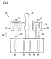
- Fig. 2 1 shows a schematic side view of a sonotrode arrangement 40 according to the invention, which comprises a sonotrode 42 and two sonotrode mounting systems 44, each having two sonotrode holders 10 arranged in alignment. Furthermore, the sonotrode assembly 40 includes an ultrasound converter 48 and a support (not shown) that attaches the sonotrode support systems 44, 46 and the ultrasound converter 48.
- the sonotrode 42 comprises elongated holes 50 and, as seen in the direction of vibration 22, has approximately the same length as the oscillating bodies 20.
- the sonotrode 42 and the sonotrode holder 10, seen in the direction of vibration 22, may be formed with equal lengths.
- the sonotrode holder 10 can thus have essentially the same resonant frequency as the sonotrode 42.
- the sonotrode mounting systems 44, 46 are keyed by means of pins 12 with the carrier, not shown.
- the ultrasonic transducer 48 produces a mechanical vibration at the resonant frequency of the sonotrode 42. This vibration is introduced into the sonotrode 42, causing the sonotrode 42 to resonate starts to swing.
- the vibrations of the sonotrode 42 are in turn passed to the oscillating bodies 20 of the sonotrode mounting systems 44, 46. Due to the attachment of the oscillating bodies 20 at a vibration node, the vibration of the resonantly vibrating oscillating bodies 20 is strongly attenuated to the suspensions 14 of the sonotrode support systems 44, 46 and thus substantially not transmitted to the carrier.
- the loads from the sonotrode 42 are distributed over the individual sonotrode holders 10 of the sonotrode holder systems 44, 46.
- the sonotrode arrangement 40 according to the invention thus makes it possible to operate the sonotrode 42 under very high mechanical loads, whereby precise guidance of the sonotrode 42 by the sonotrode holders 10 or the sonotrode holder systems 44, 46 according to the invention is ensured despite the loading.
Landscapes
- Engineering & Computer Science (AREA)
- Mechanical Engineering (AREA)
- Apparatuses For Generation Of Mechanical Vibrations (AREA)
- Pressure Welding/Diffusion-Bonding (AREA)
- Holders For Apparel And Elements Relating To Apparel (AREA)
- Supports Or Holders For Household Use (AREA)
Applications Claiming Priority (1)
| Application Number | Priority Date | Filing Date | Title |
|---|---|---|---|
| DE102012216584.3A DE102012216584A1 (de) | 2012-09-17 | 2012-09-17 | Sonotrodenhalterung |
Publications (2)
| Publication Number | Publication Date |
|---|---|
| EP2708291A2 true EP2708291A2 (fr) | 2014-03-19 |
| EP2708291A3 EP2708291A3 (fr) | 2016-12-21 |
Family
ID=49161997
Family Applications (1)
| Application Number | Title | Priority Date | Filing Date |
|---|---|---|---|
| EP13183837.7A Withdrawn EP2708291A3 (fr) | 2012-09-17 | 2013-09-11 | Support de sonotrodes |
Country Status (6)
| Country | Link |
|---|---|
| US (1) | US8978732B2 (fr) |
| EP (1) | EP2708291A3 (fr) |
| JP (1) | JP2014073491A (fr) |
| BR (1) | BR102013023793A2 (fr) |
| CA (1) | CA2826922A1 (fr) |
| DE (1) | DE102012216584A1 (fr) |
Families Citing this family (2)
| Publication number | Priority date | Publication date | Assignee | Title |
|---|---|---|---|---|
| US11273516B2 (en) * | 2020-05-01 | 2022-03-15 | Sonics & Materials, Inc. | Ultrasonic slotted cylindrical block horn |
| CN120790469B (zh) * | 2025-09-09 | 2025-12-09 | 汇中仪表股份有限公司 | 超声波换能器 |
Citations (1)
| Publication number | Priority date | Publication date | Assignee | Title |
|---|---|---|---|---|
| DE202004003917U1 (de) | 2004-03-12 | 2004-05-19 | Sonotronic Nagel Gmbh | Sonotrodenwerkzeug für eine Sonotrode |
Family Cites Families (9)
| Publication number | Priority date | Publication date | Assignee | Title |
|---|---|---|---|---|
| DE1179405B (de) * | 1959-04-10 | 1964-10-08 | Aeroprojects Inc | Halterung fuer das schwingende Element eines Ultraschallschwingers |
| US4425115A (en) * | 1977-12-19 | 1984-01-10 | Wuchinich David G | Ultrasonic resonant vibrator |
| US5922170A (en) * | 1997-10-02 | 1999-07-13 | Minnesota Mining And Manufacturing Company | Hollow vibrational horn |
| DE69926758T2 (de) * | 1998-03-23 | 2006-03-30 | Shikoku Kakoki Co., Ltd. | Ultraschall-siegler |
| GB2344487A (en) * | 1998-12-02 | 2000-06-07 | Herfurth Uk Limited | Ultrasonic resonator has slots extending through resonant body which are of non-uniform width |
| JP4603122B2 (ja) * | 2000-02-23 | 2010-12-22 | 四国化工機株式会社 | 超音波シール装置 |
| US20040047485A1 (en) * | 2002-07-16 | 2004-03-11 | Stewart Sherrit | Folded horns for vibration actuators |
| JP2006212619A (ja) * | 2005-02-07 | 2006-08-17 | Kazumasa Onishi | 超音波加工装置 |
| DE102005038344A1 (de) * | 2005-08-13 | 2007-02-15 | Tetra Laval Holdings & Finance S.A. | Vorrichtung zum Ultraschallbearbeiten von Werkstücken |
-
2012
- 2012-09-17 DE DE102012216584.3A patent/DE102012216584A1/de not_active Withdrawn
-
2013
- 2013-09-11 EP EP13183837.7A patent/EP2708291A3/fr not_active Withdrawn
- 2013-09-13 JP JP2013190934A patent/JP2014073491A/ja active Pending
- 2013-09-13 CA CA2826922A patent/CA2826922A1/fr not_active Abandoned
- 2013-09-17 US US14/029,095 patent/US8978732B2/en not_active Expired - Fee Related
- 2013-09-17 BR BR102013023793-0A patent/BR102013023793A2/pt not_active IP Right Cessation
Patent Citations (1)
| Publication number | Priority date | Publication date | Assignee | Title |
|---|---|---|---|---|
| DE202004003917U1 (de) | 2004-03-12 | 2004-05-19 | Sonotronic Nagel Gmbh | Sonotrodenwerkzeug für eine Sonotrode |
Also Published As
| Publication number | Publication date |
|---|---|
| US8978732B2 (en) | 2015-03-17 |
| CA2826922A1 (fr) | 2014-03-17 |
| US20140083622A1 (en) | 2014-03-27 |
| DE102012216584A1 (de) | 2014-03-20 |
| EP2708291A3 (fr) | 2016-12-21 |
| JP2014073491A (ja) | 2014-04-24 |
| BR102013023793A2 (pt) | 2019-05-07 |
Similar Documents
| Publication | Publication Date | Title |
|---|---|---|
| EP2288450B1 (fr) | Sonotrode pour une unité émettrice d'ultrasons | |
| DE102013209234A1 (de) | Vorrichtung mit einem schwingfähig aufgehängten optischen Element | |
| WO2015110347A1 (fr) | Ensemble convertisseur | |
| EP2208693B1 (fr) | Convoyeur linéaire de vibrations | |
| DE3215040A1 (de) | Resonanzstab | |
| EP3507028B1 (fr) | Système générateur d'ultrasons comportant un transformateur d'amplitude raccordé par la surface extérieure | |
| EP2895277B1 (fr) | Dispositif et procédé destinés au tamisage par ultra-sons | |
| EP1142651B1 (fr) | Dispositif de tamisage | |
| EP3763966A1 (fr) | Ensemble de suspension et transporteur à vibrations | |
| EP3713682B1 (fr) | Unité de vibration ultrasonore avec amortissement | |
| DE102012216584A1 (de) | Sonotrodenhalterung | |
| DE69918922T2 (de) | Ultraschall Siebvorrichtung mit verbessertem Wirkungsgrad | |
| DE102017214360A1 (de) | Vertikal vibrierende fügevorrichtung | |
| EP3679267B1 (fr) | Palier ainsi que suspension de véhicule comprenant un tel palier | |
| EP3600700B1 (fr) | Système d'usinage torsionnel par ultrasons et procédé de réglage d'un oscillateur torsionnel | |
| EP0639759A2 (fr) | Lame vibrante de mesure, plat et monopièce, à deux noeuds, pour la mesure de déplacement ou de force | |
| DE102016001385A1 (de) | Federsystem an einer Betonsteinmaschine | |
| WO2016141971A1 (fr) | Système de tamisage, tamiseur tourbillonnaire et utilisation d'un système de tamisage ou d'un tamiseur tourbillonnaire | |
| WO2016142454A2 (fr) | Système de tamisage, tamiseur tourbillonnaire et utilisation d'un système de tamisage ou d'un tamiseur tourbillonnaire | |
| EP2383066A2 (fr) | Système de fixation de sonotrodes | |
| DE102007004449A1 (de) | Stützvorrichtung für einen Wickelkopf sowie damit ausgestatteter Stator und Verfahren zum Umrüsten eines Stators | |
| EP2179318B1 (fr) | Composant micromécanique et procédé pour amorcer les oscillations d'un élément vibrant d'un composant micromécanique | |
| DE102015209030A1 (de) | Mikromechanische Vorrichtung und Verfahren zum Herstellen einer mikromechanischen Vorrichtung | |
| DE1541975B2 (de) | Elektromechanisches Bandfilter | |
| DE102006037638B4 (de) | Verfahren und Vorrichtung zum Sieben, Klassieren, Filtern oder Sortieren trockener fester Stoffe oder fester Stoffe in Flüssigkeiten |
Legal Events
| Date | Code | Title | Description |
|---|---|---|---|
| PUAI | Public reference made under article 153(3) epc to a published international application that has entered the european phase |
Free format text: ORIGINAL CODE: 0009012 |
|
| AK | Designated contracting states |
Kind code of ref document: A2 Designated state(s): AL AT BE BG CH CY CZ DE DK EE ES FI FR GB GR HR HU IE IS IT LI LT LU LV MC MK MT NL NO PL PT RO RS SE SI SK SM TR |
|
| AX | Request for extension of the european patent |
Extension state: BA ME |
|
| RAP1 | Party data changed (applicant data changed or rights of an application transferred) |
Owner name: MS ULTRASCHALL TECHNOLOGIE GMBH |
|
| PUAL | Search report despatched |
Free format text: ORIGINAL CODE: 0009013 |
|
| AK | Designated contracting states |
Kind code of ref document: A3 Designated state(s): AL AT BE BG CH CY CZ DE DK EE ES FI FR GB GR HR HU IE IS IT LI LT LU LV MC MK MT NL NO PL PT RO RS SE SI SK SM TR |
|
| AX | Request for extension of the european patent |
Extension state: BA ME |
|
| RIC1 | Information provided on ipc code assigned before grant |
Ipc: B06B 3/00 20060101AFI20161111BHEP |
|
| STAA | Information on the status of an ep patent application or granted ep patent |
Free format text: STATUS: THE APPLICATION HAS BEEN PUBLISHED |
|
| STAA | Information on the status of an ep patent application or granted ep patent |
Free format text: STATUS: THE APPLICATION IS DEEMED TO BE WITHDRAWN |
|
| 18D | Application deemed to be withdrawn |
Effective date: 20170622 |