EP2708129B1 - Baking tray with interchangeable baking inserts - Google Patents
Baking tray with interchangeable baking inserts Download PDFInfo
- Publication number
- EP2708129B1 EP2708129B1 EP13184459.9A EP13184459A EP2708129B1 EP 2708129 B1 EP2708129 B1 EP 2708129B1 EP 13184459 A EP13184459 A EP 13184459A EP 2708129 B1 EP2708129 B1 EP 2708129B1
- Authority
- EP
- European Patent Office
- Prior art keywords
- baking
- frame
- insert
- tray
- baking tray
- Prior art date
- Legal status (The legal status is an assumption and is not a legal conclusion. Google has not performed a legal analysis and makes no representation as to the accuracy of the status listed.)
- Active
Links
- 238000007373 indentation Methods 0.000 claims description 9
- 238000000034 method Methods 0.000 claims description 5
- 239000007787 solid Substances 0.000 claims description 3
- 229910052751 metal Inorganic materials 0.000 description 10
- 239000002184 metal Substances 0.000 description 10
- 235000015173 baked goods and baking mixes Nutrition 0.000 description 4
- 238000004519 manufacturing process Methods 0.000 description 3
- 238000005555 metalworking Methods 0.000 description 3
- 229910000831 Steel Inorganic materials 0.000 description 2
- 229910052782 aluminium Inorganic materials 0.000 description 2
- XAGFODPZIPBFFR-UHFFFAOYSA-N aluminium Chemical compound [Al] XAGFODPZIPBFFR-UHFFFAOYSA-N 0.000 description 2
- 238000002788 crimping Methods 0.000 description 2
- 239000012634 fragment Substances 0.000 description 2
- 239000000463 material Substances 0.000 description 2
- 230000008439 repair process Effects 0.000 description 2
- 239000010959 steel Substances 0.000 description 2
- 230000004075 alteration Effects 0.000 description 1
- 238000005520 cutting process Methods 0.000 description 1
- 238000005553 drilling Methods 0.000 description 1
- 230000007613 environmental effect Effects 0.000 description 1
- 235000013305 food Nutrition 0.000 description 1
- 239000000126 substance Substances 0.000 description 1
- 230000002459 sustained effect Effects 0.000 description 1
- 239000002699 waste material Substances 0.000 description 1
- 238000003466 welding Methods 0.000 description 1
Images


Classifications
-
- A—HUMAN NECESSITIES
- A21—BAKING; EDIBLE DOUGHS
- A21B—BAKERS' OVENS; MACHINES OR EQUIPMENT FOR BAKING
- A21B3/00—Parts or accessories of ovens
- A21B3/15—Baking sheets; Baking boards
-
- A—HUMAN NECESSITIES
- A47—FURNITURE; DOMESTIC ARTICLES OR APPLIANCES; COFFEE MILLS; SPICE MILLS; SUCTION CLEANERS IN GENERAL
- A47J—KITCHEN EQUIPMENT; COFFEE MILLS; SPICE MILLS; APPARATUS FOR MAKING BEVERAGES
- A47J37/00—Baking; Roasting; Grilling; Frying
- A47J37/01—Vessels uniquely adapted for baking
-
- A—HUMAN NECESSITIES
- A21—BAKING; EDIBLE DOUGHS
- A21B—BAKERS' OVENS; MACHINES OR EQUIPMENT FOR BAKING
- A21B3/00—Parts or accessories of ovens
- A21B3/15—Baking sheets; Baking boards
- A21B3/155—Baking sheets; Baking boards of wire or mesh wire material
Definitions
- the present invention relates generally to an article of manufacture used for industrial baking applications, and more specifically to a baking pan or tray for use in industrial and commercial applications, wherein the baking surface or baking insert portion of the tray may be easily removed and replaced with another baking insert of the same or different design.
- the invention relates to a system and method that may employ such an article.
- Baking pans or trays are commonly used by producers of various baked goods that are supplied to restaurants and grocery stores. Because producers of baked goods often supply large quantities of baked goods to their customers, the trays such goods are baked on are reused many times and are repeatedly subjected to both high thermal and mechanical stresses. Repeated exposure to high temperatures and mechanical stress requires that an industrial baking pan or tray be manufactured from a durable material such as steel or aluminum. Although manufacturing a baking tray from materials such as steel or aluminum does increase the lifespan of the tray, repeated use, re-glazing, or other physical or chemical stressors eventually weakens the metal of the tray and cracks or fractures may appear in the metal surface of the tray. Once a tray has sustained such damage, it is no longer useable and must be discarded.
- baking surface that is attached to a frame by welding (permanent) or riveting (permanent/semi-permanent), making removal and replacement of the baking surface difficult and labor-intensive. Removal and replacement of the baking surface may require metalworking methods such as drilling or grinding and may create a food safety hazard by producing metal chips and/or fragments that remain on the tray following the replacement procedure. Because baking surface replacement is labor-intensive and very difficult, trays in need of repair are often shipped to the original tray manufacturer or to a metalworking professional for performance of this work. This aspect of the repair process may add such considerable time and expense that the trays are simply discarded rather than repaired, thereby creating environmental waste and other undesirable consequences. Therefore, there is an ongoing need for an industrial/commercial baking tray that may be quickly, effectively, and inexpensively repaired when the baking insert or baking surface thereof becomes unusable.
- a first baking tray includes a frame, wherein the frame has been adapted to support a baking insert; and a baking insert, wherein certain portions of the baking insert are received by the frame, and wherein other portions of the baking insert are detachably connected to the frame.
- a second baking tray in accordance with another aspect of the present invention, includes a frame having a left portion, a right portion, a front portion, and a rear portion; wherein the left and right portions each include a channel formed lengthwise therein; and wherein the front and rear portions each include a crossbar extending widthwise across the frame; and a baking insert having a left portion, a right portion, a front portion, and a rear portion; wherein the left and right portions each include a folded region, the geometry of which corresponds to the channels formed lengthwise in the frame; and wherein the front and rear portions each include at least one tab which is adapted to releasably engage the crossbars extending widthwise across the frame.
- a baking tray system in yet another aspect of this invention, includes at least one frame having a left portion, a right portion, a front portion, and a rear portion; wherein the left and right portions each include a channel formed lengthwise therein; and wherein the front and rear portions each include a crossbar extending widthwise across the frame and; at least one baking insert having a left portion, a right portion, a front portion, and a rear portion; wherein the left and right portions each include a folded region, the geometry of which corresponds to the channels formed lengthwise in the frame; and wherein the front and rear portions each include a plurality of tabs that are adapted to releasably engage the crossbars extending widthwise across the frame.
- This system also includes at least one tool for connecting the tabs to the crossbars; and at least one tool for detaching the tabs from the crossbars.
- the present invention relates generally to an article of manufacture used for industrial baking applications, and more specifically to a baking pan or tray for use in industrial and commercial applications, wherein the baking surface or baking insert of the tray may be easily removed and replaced with another baking insert of the same or different general design.
- the present invention may be provided as a system that includes multiple frames; multiple interchangeable baking inserts, at least one tool for connecting the baking inserts to the frame; and at least one tool for detaching the baking inserts from the frame.
- This system allows baking inserts to be easily installed, removed, or changed from one baking surface type to another in a bakery environment without the use of metalworking or cutting tools that may create dangerous metal shards or metal fragments.
- the frames and baking inserts included with this invention are typically fabricated using known methodologies. With reference now to FIGS. 1-6 , one or more exemplary embodiments of this invention will be described in greater detail.
- a first exemplary baking tray 110 includes metal frame 120 and metal baking insert 150, which is detachably connected to the frame.
- Frame 120 is generally rectangular in shape and includes left side portion 122, right side portion 130, front portion 140, and rear portion 144.
- Left side portion 122 further includes channel 124, protrusions 126, and indentations 128.
- Right side portion 130 further includes channel 132 (not shown), protrusions 136 and indentations 138.
- Front portion 140 further includes front crossbar 142; and rear portion 144 further includes rear crossbar 146.
- Baking insert 150 which is also rectangular in shape, includes baking surface 152 and plurality of elongated baking subunits 154 (useful for baguettes or the like), which may be substantially solid, or partially or completely perforated. Baking insert 150 further includes left side portion 156 having a first folded region 158; right side portion 160 having a second folded region 162; front portion 164 having a plurality of tabs 166; and a rear portion 168 also having a plurality of tabs 170 (not shown). As shown in FIG.
- first folded region 158 is inserted into channel 124; second folded region 162 is inserted into channel 132; tabs 166 are folded or crimped around front crossbar 142; and tabs 170 (not shown) are folded or crimped around rear crossbar 146.
- a second exemplary baking tray 210 includes metal frame 120 and metal baking insert 250, which although different in configuration, is mounted on and attached to metal frame 120 in the same manner as the previously described embodiment.
- Frame 120 incudes left side portion 122, right side portion 130, front portion 140, and rear portion 144.
- Left side portion 122 further includes channel 124, protrusions 126, and indentations 128.
- Right side portion 130 further includes channel 132 (not shown), protrusions 136 and indentations 138.
- Front portion 140 further includes front crossbar 142, and rear portion 144 further includes rear crossbar 146.
- Baking insert 250 includes baking surface 252, which may be substantially solid or partially or completely perforated.
- Baking insert 250 further includes left side portion 256 having a first folded region 258; right side portion 260 having a second folded region 262; front portion 264 having a plurality of tabs 266; and a rear portion 268 also having a plurality of tabs 270 (not shown).
- first folded region 258 is inserted into channel 124; second folded region 262 is inserted into channel 132; tabs 266 are folded or crimped around front crossbar 142; and tabs 170 (not shown) are folded or crimped around rear crossbar 146.
- tabs 170 and 270 are typically attached to the crossbars of frame 120 using a crimping tool that has been designed specifically for use with the baking trays of the present invention, or that has been adapted for use with these trays. Similarly, tabs 170 and 270 are released from crossbars 142 and 146 using a prying or releasing tool that has been either designed specifically for use with the baking trays of the present invention, or that has been adapted for use with these trays. Removing the baking insert in this manner does not damage frame 120 and thus allows frame 120 to be used and re-used with various baking inserts that are replacements for damaged or worn baking inserts or that are intended to be used to create other types of baked goods.
- the baking trays of the present invention are also intended to be stackable, and protrusions 126 and 136 and indentations 128 and 138 are included on frame 120 to provide this feature.
- the indentations on the bottom of a tray receive the protrusions on the top of another tray and together these structures allow the baking trays of this invention to be securely stacked on top of one another.
Description
- The present invention relates generally to an article of manufacture used for industrial baking applications, and more specifically to a baking pan or tray for use in industrial and commercial applications, wherein the baking surface or baking insert portion of the tray may be easily removed and replaced with another baking insert of the same or different design.
- In further aspects, the invention relates to a system and method that may employ such an article.
- Baking pans or trays are commonly used by producers of various baked goods that are supplied to restaurants and grocery stores. Because producers of baked goods often supply large quantities of baked goods to their customers, the trays such goods are baked on are reused many times and are repeatedly subjected to both high thermal and mechanical stresses. Repeated exposure to high temperatures and mechanical stress requires that an industrial baking pan or tray be manufactured from a durable material such as steel or aluminum. Although manufacturing a baking tray from materials such as steel or aluminum does increase the lifespan of the tray, repeated use, re-glazing, or other physical or chemical stressors eventually weakens the metal of the tray and cracks or fractures may appear in the metal surface of the tray. Once a tray has sustained such damage, it is no longer useable and must be discarded. Due to the significant expense of replacing industrial baking trays, additional features may be included to prolong the usable life of these trays. One such feature is a replaceable baking insert/surface that is attached to the body or frame of the tray. Documents
WO9322925A1 US20040055475A1 ,ES1014674U DE29905978U1 disclose baking trays with baking inserts according to the prior art. - Currently used industrial/commercial baking trays of this nature often include a baking surface that is attached to a frame by welding (permanent) or riveting (permanent/semi-permanent), making removal and replacement of the baking surface difficult and labor-intensive. Removal and replacement of the baking surface may require metalworking methods such as drilling or grinding and may create a food safety hazard by producing metal chips and/or fragments that remain on the tray following the replacement procedure. Because baking surface replacement is labor-intensive and very difficult, trays in need of repair are often shipped to the original tray manufacturer or to a metalworking professional for performance of this work. This aspect of the repair process may add such considerable time and expense that the trays are simply discarded rather than repaired, thereby creating environmental waste and other undesirable consequences. Therefore, there is an ongoing need for an industrial/commercial baking tray that may be quickly, effectively, and inexpensively repaired when the baking insert or baking surface thereof becomes unusable.
- The following provides a summary of certain exemplary embodiments of the present invention. This summary is not an extensive overview and is not intended to identify key or critical aspects or elements of the present invention or to delineate its scope.
- In accordance with one aspect of the present invention, a first baking tray is provided. This baking tray includes a frame, wherein the frame has been adapted to support a baking insert; and a baking insert, wherein certain portions of the baking insert are received by the frame, and wherein other portions of the baking insert are detachably connected to the frame.
- In accordance with another aspect of the present invention, a second baking tray is provided. This baking tray includes a frame having a left portion, a right portion, a front portion, and a rear portion; wherein the left and right portions each include a channel formed lengthwise therein; and wherein the front and rear portions each include a crossbar extending widthwise across the frame; and a baking insert having a left portion, a right portion, a front portion, and a rear portion; wherein the left and right portions each include a folded region, the geometry of which corresponds to the channels formed lengthwise in the frame; and wherein the front and rear portions each include at least one tab which is adapted to releasably engage the crossbars extending widthwise across the frame.
- In yet another aspect of this invention, a baking tray system is provided. This baking tray system includes at least one frame having a left portion, a right portion, a front portion, and a rear portion; wherein the left and right portions each include a channel formed lengthwise therein; and wherein the front and rear portions each include a crossbar extending widthwise across the frame and; at least one baking insert having a left portion, a right portion, a front portion, and a rear portion; wherein the left and right portions each include a folded region, the geometry of which corresponds to the channels formed lengthwise in the frame; and wherein the front and rear portions each include a plurality of tabs that are adapted to releasably engage the crossbars extending widthwise across the frame. This system also includes at least one tool for connecting the tabs to the crossbars; and at least one tool for detaching the tabs from the crossbars.
- Additional features and aspects of the present invention will become apparent to those of ordinary skill in the art upon reading and understanding the following detailed description of the exemplary embodiments.
- The accompanying drawings, which are incorporated into and form a part of the specification, schematically illustrate one or more exemplary embodiments of the invention and, together with the general description given above and detailed description given below, serve to explain the principles of the invention, and wherein:
-
FIG. 1 is a perspective view of a baking tray in accordance with a first exemplary embodiment of the present invention; -
FIG. 2A is a perspective view of the frame component of the baking tray ofFIG. 1 ; -
FIG. 2B is a perspective view of the baking insert component of the baking tray ofFIG. 1 ; -
FIG. 3 is a perspective view of one end of the baking insert of the baking tray ofFIG. 1 showing one of the tabs used to connect the baking insert to the frame; -
FIG. 4 is a perspective view of a baking tray in accordance with a second exemplary embodiment of the present invention; -
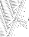
FIG. 5 shows a connecting tool being used to attach the baking insert to the frame by crimping the tab shown inFIG.3 ; and -
FIG. 6 shows a detaching tool being used to disconnect the baking insert from the frame by loosening the tab shown inFIG. 3 . - Exemplary embodiments of the present invention are now described with reference to the Figures. Although the following detailed description contains many specifics for purposes of illustration, a person of ordinary skill in the art will appreciate that many variations and alterations to the following details are within the scope of the invention. Accordingly, the following embodiments of the invention are set forth without any loss of generality to, and without imposing limitations upon, the claimed invention.
- As previously stated, the present invention relates generally to an article of manufacture used for industrial baking applications, and more specifically to a baking pan or tray for use in industrial and commercial applications, wherein the baking surface or baking insert of the tray may be easily removed and replaced with another baking insert of the same or different general design. The present invention may be provided as a system that includes multiple frames; multiple interchangeable baking inserts, at least one tool for connecting the baking inserts to the frame; and at least one tool for detaching the baking inserts from the frame. This system allows baking inserts to be easily installed, removed, or changed from one baking surface type to another in a bakery environment without the use of metalworking or cutting tools that may create dangerous metal shards or metal fragments. The frames and baking inserts included with this invention are typically fabricated using known methodologies. With reference now to
FIGS. 1-6 , one or more exemplary embodiments of this invention will be described in greater detail. - As best shown in
FIGS. 1 and2A-B , a firstexemplary baking tray 110 includesmetal frame 120 andmetal baking insert 150, which is detachably connected to the frame.Frame 120 is generally rectangular in shape and includesleft side portion 122,right side portion 130,front portion 140, and rear portion 144.Left side portion 122 further includeschannel 124,protrusions 126, andindentations 128.Right side portion 130 further includes channel 132 (not shown),protrusions 136 andindentations 138.Front portion 140 further includesfront crossbar 142; and rear portion 144 further includesrear crossbar 146.Baking insert 150, which is also rectangular in shape, includesbaking surface 152 and plurality of elongated baking subunits 154 (useful for baguettes or the like), which may be substantially solid, or partially or completely perforated.Baking insert 150 further includes left side portion 156 having a first foldedregion 158;right side portion 160 having a second foldedregion 162;front portion 164 having a plurality oftabs 166; and a rear portion 168 also having a plurality of tabs 170 (not shown). As shown inFIG. 1 , whenbaking tray 110 is properly assembled, first foldedregion 158 is inserted intochannel 124; second foldedregion 162 is inserted into channel 132;tabs 166 are folded or crimped aroundfront crossbar 142; and tabs 170 (not shown) are folded or crimped aroundrear crossbar 146. - As shown in
FIG. 4 , a secondexemplary baking tray 210 includesmetal frame 120 and metal baking insert 250, which although different in configuration, is mounted on and attached tometal frame 120 in the same manner as the previously described embodiment.Frame 120 incudesleft side portion 122,right side portion 130,front portion 140, and rear portion 144.Left side portion 122 further includeschannel 124,protrusions 126, andindentations 128.Right side portion 130 further includes channel 132 (not shown),protrusions 136 andindentations 138.Front portion 140 further includesfront crossbar 142, and rear portion 144 further includesrear crossbar 146. Baking insert 250 includesbaking surface 252, which may be substantially solid or partially or completely perforated. Baking insert 250 further includes left side portion 256 having a first folded region 258; right side portion 260 having a second folded region 262; front portion 264 having a plurality oftabs 266; and a rear portion 268 also having a plurality of tabs 270 (not shown). As shown inFIG. 4 , whenbaking tray 210 is properly assembled, first folded region 258 is inserted intochannel 124; second folded region 262 is inserted into channel 132;tabs 266 are folded or crimped aroundfront crossbar 142; and tabs 170 (not shown) are folded or crimped aroundrear crossbar 146. - With reference to
FIGS. 5 and6 , tabs 170 and 270 are typically attached to the crossbars offrame 120 using a crimping tool that has been designed specifically for use with the baking trays of the present invention, or that has been adapted for use with these trays. Similarly, tabs 170 and 270 are released fromcrossbars frame 120 and thus allowsframe 120 to be used and re-used with various baking inserts that are replacements for damaged or worn baking inserts or that are intended to be used to create other types of baked goods. The baking trays of the present invention are also intended to be stackable, andprotrusions indentations frame 120 to provide this feature. The indentations on the bottom of a tray receive the protrusions on the top of another tray and together these structures allow the baking trays of this invention to be securely stacked on top of one another.
Claims (12)
- A baking tray (110,210), comprising:(a) a frame (120) configured to support a baking insert (150,250); wherein said frame (120) includes a left portion (122), a right portion (130), a front portion (140), and a rear portion (144); and wherein the front and rear portions (140,144) each include a crossbar (142,146) extending widthwise across the frame (120); and(b) a baking insert (150;250), wherein certain portions (158,162;258,262) of the baking insert are received by the frame (124,132), and wherein other portions (166,170, 266, 270) of the baking insert are detachably connected to the frame; wherein said baking inserts (150;250) includes a left portion (156;256), a right portion (160;260), a front portion (164;264), and a rear portion (168;268); characterised in that the outermost edges of the front and rear portions (164,168;264,268) of the baking insert (150;250) each include at least one tab (166) formed thereon prior to the attachment of the baking insert (150;250) to the frame (120), which tab (166) is adapted to be folded or crimped around a respective crossbar (142,146) to releasably engage said crossbars (142,146) extending widthwise across the frame.
- The baking tray (110;210) of claim 1, wherein the left and right portions (120,122) each include a channel (124, 132) formed lengthwise therein; and wherein the left and right portions (156,160;256,260) of the baking insert (150;250) each include a folded region (158,162;258,262) the geometry of which corresponds to the channels (124,132) formed lengthwise in the frame, such that the folded regions (158,162;258,262) can be inserted into the corresponding channels (124,132) in the frame (120).
- The baking tray (110;210) of claim 1, wherein the frame (120) further comprises a plurality of protrusions (126) and indentations (128) formed therein for allowing the baking tray to securely stack with other baking trays having corresponding protrusions (128), and indentations.
- The baking tray of claim 3, wherein the left and right portions (122,130) of the frame each include at least one said protrusion (126) formed on the uppermost surface thereof, and at least one said indentation (128) formed in the bottommost surface thereof.
- The baking tray (210) of any preceding claim, wherein the baking insert (250) has a single baking surface (252) formed thereon.
- The baking tray (110) of any of claims 1 to 4, wherein the baking insert (150) has a plurality of individual baking subunits (154) formed therein.
- The baking tray (110;210) of any preceding claim, wherein the baking insert (150;250) is perforated.
- The baking tray (110;210) of any of claims 1 to 6, wherein the baking insert (150;250) is substantially solid.
- A baking tray system comprising: a baking tray (110;210) as defined in any preceding claim comprising a frame (120) and a baking insert (150;250); and respective tools (300) for connecting and disconnecting the frame and the insert.
- A baking system according to claim 9, wherein said tools comprise:(c) at least one tool for connecting the tabs to the crossbars; and(d) at least one tool for detaching the tabs from the crossbars.
- A baking system according to claims 9 or 10 including a plurality of different interchangeable baking inserts such that an insert can be selected from the plurality and detachably connected to the frame.
- A method of baking comprising providing a system according to any of claims 9 to 11 and producing a baking tray according to any of claims 1 to 8 by connecting a baking insert to a frame.
Priority Applications (1)
| Application Number | Priority Date | Filing Date | Title |
|---|---|---|---|
| PL13184459T PL2708129T3 (en) | 2012-09-14 | 2013-09-13 | Baking tray with interchangeable baking inserts |
Applications Claiming Priority (1)
| Application Number | Priority Date | Filing Date | Title |
|---|---|---|---|
| US201261701150P | 2012-09-14 | 2012-09-14 |
Publications (2)
| Publication Number | Publication Date |
|---|---|
| EP2708129A1 EP2708129A1 (en) | 2014-03-19 |
| EP2708129B1 true EP2708129B1 (en) | 2018-11-07 |
Family
ID=49223583
Family Applications (1)
| Application Number | Title | Priority Date | Filing Date |
|---|---|---|---|
| EP13184459.9A Active EP2708129B1 (en) | 2012-09-14 | 2013-09-13 | Baking tray with interchangeable baking inserts |
Country Status (6)
| Country | Link |
|---|---|
| US (2) | US20150282667A9 (en) |
| EP (1) | EP2708129B1 (en) |
| ES (1) | ES2708701T3 (en) |
| PL (1) | PL2708129T3 (en) |
| PT (1) | PT2708129T (en) |
| TR (1) | TR201900429T4 (en) |
Families Citing this family (10)
| Publication number | Priority date | Publication date | Assignee | Title |
|---|---|---|---|---|
| USD801689S1 (en) * | 2014-04-08 | 2017-11-07 | Health Savvy, Llc | Support device |
| USD751291S1 (en) * | 2015-01-20 | 2016-03-15 | Macneil Ip Llc | Boot tray |
| CN106308539A (en) * | 2015-06-17 | 2017-01-11 | 镇江江城金属制品有限公司 | Barbecue tray |
| US10702098B2 (en) | 2016-07-21 | 2020-07-07 | Whirlpool Corporation | Oven based non-powered accessory system |
| GB2569095B (en) * | 2017-10-16 | 2020-06-17 | Wilkinson China Ltd | Heatproof carrier for food preparation and method |
| USD844350S1 (en) * | 2018-02-27 | 2019-04-02 | Umbra Llc | Shoe rack |
| IT202000031784A1 (en) * | 2020-12-22 | 2022-06-22 | Omev Snc Di Virginio E Figli | OVEN TRAY FOR COOKING BREADSTICKS WITH COMPENSATION SYSTEM FOR THERMAL EXPANSION DIFFERENCES OF ITS COMPONENTS |
| USD1024638S1 (en) * | 2021-08-31 | 2024-04-30 | Target Brands, Inc. | Display unit insert |
| IT202100023246A1 (en) | 2021-09-08 | 2023-03-08 | Niceqlife Di Lazzaroni Andina Giulio E C S A S | Industrial baking tray with interchangeable insert |
| USD982968S1 (en) | 2022-10-03 | 2023-04-11 | Christopher M. Weber | Cooking pan |
Citations (2)
| Publication number | Priority date | Publication date | Assignee | Title |
|---|---|---|---|---|
| DE29905978U1 (en) * | 1999-04-08 | 1999-07-29 | Mueller Brot Gmbh | Baking tray arrangement |
| ES2171100A1 (en) * | 1999-08-13 | 2002-08-16 | Talleres Caselli S A | Bread baking tray centering and location system includes a snap fit type U sections and tongued guide assembly |
Family Cites Families (9)
| Publication number | Priority date | Publication date | Assignee | Title |
|---|---|---|---|---|
| US3184071A (en) * | 1962-12-12 | 1965-05-18 | Eastman Kodak Co | Plastic case for containers |
| US3482707A (en) * | 1967-09-27 | 1969-12-09 | Manny L Weiss | Dish washing rack |
| US4296682A (en) * | 1978-11-29 | 1981-10-27 | Thompson Jerome B | English muffin, method and apparatus |
| ES1014674Y (en) * | 1990-07-05 | 1991-10-01 | Bayo Molla Jacinto | INTERCHANGEABLE COATING FOR BREAD AND SIMILAR OVEN TRAYS. |
| GB2266831A (en) * | 1992-05-08 | 1993-11-17 | Runex Ltd | Bakery equipment |
| US20030038137A1 (en) * | 2001-08-21 | 2003-02-27 | American Pan Company | Baking pan system |
| FR2829671B1 (en) * | 2001-09-19 | 2004-01-02 | Erick Canicas | DISPOSABLE SUPPORT FOR THE BAKING OF BAKERY OR OTHER BUTTONS, FOR THEIR BAKING, AND MANUFACTURING METHOD THEREOF |
| US20050238772A1 (en) * | 2004-04-23 | 2005-10-27 | Stease Robert E | Bakery tray and process for baking food batter |
| US8857652B2 (en) * | 2012-04-18 | 2014-10-14 | Advanced Flexible Composites, Inc. | Cooking support with removable mesh insert |
-
2013
- 2013-09-13 PT PT13184459T patent/PT2708129T/en unknown
- 2013-09-13 EP EP13184459.9A patent/EP2708129B1/en active Active
- 2013-09-13 TR TR2019/00429T patent/TR201900429T4/en unknown
- 2013-09-13 PL PL13184459T patent/PL2708129T3/en unknown
- 2013-09-13 ES ES13184459T patent/ES2708701T3/en active Active
- 2013-09-16 US US14/027,276 patent/US20150282667A9/en not_active Abandoned
-
2016
- 2016-09-21 US US15/272,096 patent/US20170007070A1/en not_active Abandoned
Patent Citations (2)
| Publication number | Priority date | Publication date | Assignee | Title |
|---|---|---|---|---|
| DE29905978U1 (en) * | 1999-04-08 | 1999-07-29 | Mueller Brot Gmbh | Baking tray arrangement |
| ES2171100A1 (en) * | 1999-08-13 | 2002-08-16 | Talleres Caselli S A | Bread baking tray centering and location system includes a snap fit type U sections and tongued guide assembly |
Also Published As
| Publication number | Publication date |
|---|---|
| EP2708129A1 (en) | 2014-03-19 |
| PL2708129T3 (en) | 2019-04-30 |
| US20150282667A9 (en) | 2015-10-08 |
| ES2708701T3 (en) | 2019-04-10 |
| US20170007070A1 (en) | 2017-01-12 |
| PT2708129T (en) | 2019-02-04 |
| US20150076158A1 (en) | 2015-03-19 |
| TR201900429T4 (en) | 2019-02-21 |
Similar Documents
| Publication | Publication Date | Title |
|---|---|---|
| EP2708129B1 (en) | Baking tray with interchangeable baking inserts | |
| KR101611844B1 (en) | Tire vulcanization forming mold | |
| US8348089B2 (en) | Industrial baking tray with contoured reinforcement band | |
| US20180162018A1 (en) | Cutter for trimming tread of tire | |
| KR101648491B1 (en) | Link member having replaceable wear component | |
| USD828713S1 (en) | Sear station for a pellet grill style barbeque | |
| JP6754683B2 (en) | Tire mold and tire mold manufacturing method | |
| JP5863618B2 (en) | Hanging tool for attaching / detaching dies | |
| US20140298631A1 (en) | Tool for removing piston ring | |
| KR101839570B1 (en) | Round bar cutting device | |
| US3182397A (en) | Cake release cutter | |
| US20080236231A1 (en) | Die apparatus and method for high temperature forming of metal products | |
| JP6119396B2 (en) | Sintering machine pallet | |
| EP3156750B1 (en) | Shelf for thermal processing | |
| EP4052837B1 (en) | A table for holding a beam-cut piece of material, a system for handling beam-cut parts with such table ; method of handling beam-cut parts | |
| EP0801899A2 (en) | Bakeware apparatus | |
| EP1542537B1 (en) | Compound food recipient | |
| US20070114191A1 (en) | Positioning rack for thin-type electrothermal straps | |
| JP3045507U (en) | Sheet material used for bread baking molds | |
| KR100610623B1 (en) | A cutting frame able to partial change of cutter and it's manufacturing method | |
| KR200467217Y1 (en) | Knife holder | |
| RU61612U1 (en) | DEVICE FOR REPLACING CUTTING LININGS | |
| KR101409473B1 (en) | Slag remove rake for cutting table | |
| CN102466253A (en) | Panel strcuture for removing cooking oil | |
| JP3197240U (en) | Auxiliary tools for manufacturing baked goods |
Legal Events
| Date | Code | Title | Description |
|---|---|---|---|
| PUAI | Public reference made under article 153(3) epc to a published international application that has entered the european phase |
Free format text: ORIGINAL CODE: 0009012 |
|
| AK | Designated contracting states |
Kind code of ref document: A1 Designated state(s): AL AT BE BG CH CY CZ DE DK EE ES FI FR GB GR HR HU IE IS IT LI LT LU LV MC MK MT NL NO PL PT RO RS SE SI SK SM TR |
|
| AX | Request for extension of the european patent |
Extension state: BA ME |
|
| 17P | Request for examination filed |
Effective date: 20140918 |
|
| RBV | Designated contracting states (corrected) |
Designated state(s): AL AT BE BG CH CY CZ DE DK EE ES FI FR GB GR HR HU IE IS IT LI LT LU LV MC MK MT NL NO PL PT RO RS SE SI SK SM TR |
|
| STAA | Information on the status of an ep patent application or granted ep patent |
Free format text: STATUS: EXAMINATION IS IN PROGRESS |
|
| 17Q | First examination report despatched |
Effective date: 20170118 |
|
| REG | Reference to a national code |
Ref country code: DE Ref legal event code: R079 Ref document number: 602013046234 Country of ref document: DE Free format text: PREVIOUS MAIN CLASS: A21B0003150000 Ipc: A47J0037010000 |
|
| GRAP | Despatch of communication of intention to grant a patent |
Free format text: ORIGINAL CODE: EPIDOSNIGR1 |
|
| STAA | Information on the status of an ep patent application or granted ep patent |
Free format text: STATUS: GRANT OF PATENT IS INTENDED |
|
| RIC1 | Information provided on ipc code assigned before grant |
Ipc: A47J 37/01 20060101AFI20180528BHEP Ipc: A21B 3/15 20060101ALI20180528BHEP |
|
| INTG | Intention to grant announced |
Effective date: 20180629 |
|
| GRAS | Grant fee paid |
Free format text: ORIGINAL CODE: EPIDOSNIGR3 |
|
| GRAA | (expected) grant |
Free format text: ORIGINAL CODE: 0009210 |
|
| STAA | Information on the status of an ep patent application or granted ep patent |
Free format text: STATUS: THE PATENT HAS BEEN GRANTED |
|
| AK | Designated contracting states |
Kind code of ref document: B1 Designated state(s): AL AT BE BG CH CY CZ DE DK EE ES FI FR GB GR HR HU IE IS IT LI LT LU LV MC MK MT NL NO PL PT RO RS SE SI SK SM TR |
|
| REG | Reference to a national code |
Ref country code: GB Ref legal event code: FG4D |
|
| REG | Reference to a national code |
Ref country code: AT Ref legal event code: REF Ref document number: 1061089 Country of ref document: AT Kind code of ref document: T Effective date: 20181115 Ref country code: CH Ref legal event code: EP |
|
| REG | Reference to a national code |
Ref country code: IE Ref legal event code: FG4D |
|
| REG | Reference to a national code |
Ref country code: DE Ref legal event code: R096 Ref document number: 602013046234 Country of ref document: DE |
|
| REG | Reference to a national code |
Ref country code: RO Ref legal event code: EPE |
|
| REG | Reference to a national code |
Ref country code: PT Ref legal event code: SC4A Ref document number: 2708129 Country of ref document: PT Date of ref document: 20190204 Kind code of ref document: T Free format text: AVAILABILITY OF NATIONAL TRANSLATION Effective date: 20190128 |
|
| REG | Reference to a national code |
Ref country code: NL Ref legal event code: FP |
|
| REG | Reference to a national code |
Ref country code: LT Ref legal event code: MG4D |
|
| REG | Reference to a national code |
Ref country code: ES Ref legal event code: FG2A Ref document number: 2708701 Country of ref document: ES Kind code of ref document: T3 Effective date: 20190410 |
|
| REG | Reference to a national code |
Ref country code: AT Ref legal event code: MK05 Ref document number: 1061089 Country of ref document: AT Kind code of ref document: T Effective date: 20181107 |
|
| PG25 | Lapsed in a contracting state [announced via postgrant information from national office to epo] |
Ref country code: HR Free format text: LAPSE BECAUSE OF FAILURE TO SUBMIT A TRANSLATION OF THE DESCRIPTION OR TO PAY THE FEE WITHIN THE PRESCRIBED TIME-LIMIT Effective date: 20181107 Ref country code: LV Free format text: LAPSE BECAUSE OF FAILURE TO SUBMIT A TRANSLATION OF THE DESCRIPTION OR TO PAY THE FEE WITHIN THE PRESCRIBED TIME-LIMIT Effective date: 20181107 Ref country code: FI Free format text: LAPSE BECAUSE OF FAILURE TO SUBMIT A TRANSLATION OF THE DESCRIPTION OR TO PAY THE FEE WITHIN THE PRESCRIBED TIME-LIMIT Effective date: 20181107 Ref country code: LT Free format text: LAPSE BECAUSE OF FAILURE TO SUBMIT A TRANSLATION OF THE DESCRIPTION OR TO PAY THE FEE WITHIN THE PRESCRIBED TIME-LIMIT Effective date: 20181107 Ref country code: NO Free format text: LAPSE BECAUSE OF FAILURE TO SUBMIT A TRANSLATION OF THE DESCRIPTION OR TO PAY THE FEE WITHIN THE PRESCRIBED TIME-LIMIT Effective date: 20190207 Ref country code: BG Free format text: LAPSE BECAUSE OF FAILURE TO SUBMIT A TRANSLATION OF THE DESCRIPTION OR TO PAY THE FEE WITHIN THE PRESCRIBED TIME-LIMIT Effective date: 20190207 Ref country code: IS Free format text: LAPSE BECAUSE OF FAILURE TO SUBMIT A TRANSLATION OF THE DESCRIPTION OR TO PAY THE FEE WITHIN THE PRESCRIBED TIME-LIMIT Effective date: 20190307 Ref country code: AT Free format text: LAPSE BECAUSE OF FAILURE TO SUBMIT A TRANSLATION OF THE DESCRIPTION OR TO PAY THE FEE WITHIN THE PRESCRIBED TIME-LIMIT Effective date: 20181107 |
|
| PG25 | Lapsed in a contracting state [announced via postgrant information from national office to epo] |
Ref country code: GR Free format text: LAPSE BECAUSE OF FAILURE TO SUBMIT A TRANSLATION OF THE DESCRIPTION OR TO PAY THE FEE WITHIN THE PRESCRIBED TIME-LIMIT Effective date: 20190208 Ref country code: AL Free format text: LAPSE BECAUSE OF FAILURE TO SUBMIT A TRANSLATION OF THE DESCRIPTION OR TO PAY THE FEE WITHIN THE PRESCRIBED TIME-LIMIT Effective date: 20181107 Ref country code: RS Free format text: LAPSE BECAUSE OF FAILURE TO SUBMIT A TRANSLATION OF THE DESCRIPTION OR TO PAY THE FEE WITHIN THE PRESCRIBED TIME-LIMIT Effective date: 20181107 Ref country code: SE Free format text: LAPSE BECAUSE OF FAILURE TO SUBMIT A TRANSLATION OF THE DESCRIPTION OR TO PAY THE FEE WITHIN THE PRESCRIBED TIME-LIMIT Effective date: 20181107 |
|
| PG25 | Lapsed in a contracting state [announced via postgrant information from national office to epo] |
Ref country code: CZ Free format text: LAPSE BECAUSE OF FAILURE TO SUBMIT A TRANSLATION OF THE DESCRIPTION OR TO PAY THE FEE WITHIN THE PRESCRIBED TIME-LIMIT Effective date: 20181107 Ref country code: DK Free format text: LAPSE BECAUSE OF FAILURE TO SUBMIT A TRANSLATION OF THE DESCRIPTION OR TO PAY THE FEE WITHIN THE PRESCRIBED TIME-LIMIT Effective date: 20181107 |
|
| REG | Reference to a national code |
Ref country code: DE Ref legal event code: R097 Ref document number: 602013046234 Country of ref document: DE |
|
| PG25 | Lapsed in a contracting state [announced via postgrant information from national office to epo] |
Ref country code: SM Free format text: LAPSE BECAUSE OF FAILURE TO SUBMIT A TRANSLATION OF THE DESCRIPTION OR TO PAY THE FEE WITHIN THE PRESCRIBED TIME-LIMIT Effective date: 20181107 Ref country code: EE Free format text: LAPSE BECAUSE OF FAILURE TO SUBMIT A TRANSLATION OF THE DESCRIPTION OR TO PAY THE FEE WITHIN THE PRESCRIBED TIME-LIMIT Effective date: 20181107 Ref country code: SK Free format text: LAPSE BECAUSE OF FAILURE TO SUBMIT A TRANSLATION OF THE DESCRIPTION OR TO PAY THE FEE WITHIN THE PRESCRIBED TIME-LIMIT Effective date: 20181107 |
|
| PLBE | No opposition filed within time limit |
Free format text: ORIGINAL CODE: 0009261 |
|
| STAA | Information on the status of an ep patent application or granted ep patent |
Free format text: STATUS: NO OPPOSITION FILED WITHIN TIME LIMIT |
|
| 26N | No opposition filed |
Effective date: 20190808 |
|
| PG25 | Lapsed in a contracting state [announced via postgrant information from national office to epo] |
Ref country code: SI Free format text: LAPSE BECAUSE OF FAILURE TO SUBMIT A TRANSLATION OF THE DESCRIPTION OR TO PAY THE FEE WITHIN THE PRESCRIBED TIME-LIMIT Effective date: 20181107 |
|
| PG25 | Lapsed in a contracting state [announced via postgrant information from national office to epo] |
Ref country code: MC Free format text: LAPSE BECAUSE OF FAILURE TO SUBMIT A TRANSLATION OF THE DESCRIPTION OR TO PAY THE FEE WITHIN THE PRESCRIBED TIME-LIMIT Effective date: 20181107 |
|
| REG | Reference to a national code |
Ref country code: CH Ref legal event code: PL |
|
| PG25 | Lapsed in a contracting state [announced via postgrant information from national office to epo] |
Ref country code: LI Free format text: LAPSE BECAUSE OF NON-PAYMENT OF DUE FEES Effective date: 20190930 Ref country code: IE Free format text: LAPSE BECAUSE OF NON-PAYMENT OF DUE FEES Effective date: 20190913 Ref country code: LU Free format text: LAPSE BECAUSE OF NON-PAYMENT OF DUE FEES Effective date: 20190913 Ref country code: CH Free format text: LAPSE BECAUSE OF NON-PAYMENT OF DUE FEES Effective date: 20190930 |
|
| PG25 | Lapsed in a contracting state [announced via postgrant information from national office to epo] |
Ref country code: CY Free format text: LAPSE BECAUSE OF FAILURE TO SUBMIT A TRANSLATION OF THE DESCRIPTION OR TO PAY THE FEE WITHIN THE PRESCRIBED TIME-LIMIT Effective date: 20181107 |
|
| PG25 | Lapsed in a contracting state [announced via postgrant information from national office to epo] |
Ref country code: HU Free format text: LAPSE BECAUSE OF FAILURE TO SUBMIT A TRANSLATION OF THE DESCRIPTION OR TO PAY THE FEE WITHIN THE PRESCRIBED TIME-LIMIT; INVALID AB INITIO Effective date: 20130913 Ref country code: MT Free format text: LAPSE BECAUSE OF FAILURE TO SUBMIT A TRANSLATION OF THE DESCRIPTION OR TO PAY THE FEE WITHIN THE PRESCRIBED TIME-LIMIT Effective date: 20181107 |
|
| PG25 | Lapsed in a contracting state [announced via postgrant information from national office to epo] |
Ref country code: MK Free format text: LAPSE BECAUSE OF FAILURE TO SUBMIT A TRANSLATION OF THE DESCRIPTION OR TO PAY THE FEE WITHIN THE PRESCRIBED TIME-LIMIT Effective date: 20181107 |
|
| PGFP | Annual fee paid to national office [announced via postgrant information from national office to epo] |
Ref country code: NL Payment date: 20230809 Year of fee payment: 11 |
|
| PGFP | Annual fee paid to national office [announced via postgrant information from national office to epo] |
Ref country code: TR Payment date: 20230727 Year of fee payment: 11 Ref country code: RO Payment date: 20230731 Year of fee payment: 11 Ref country code: IT Payment date: 20230727 Year of fee payment: 11 Ref country code: GB Payment date: 20230821 Year of fee payment: 11 |
|
| PGFP | Annual fee paid to national office [announced via postgrant information from national office to epo] |
Ref country code: PT Payment date: 20230719 Year of fee payment: 11 Ref country code: PL Payment date: 20230720 Year of fee payment: 11 Ref country code: FR Payment date: 20230817 Year of fee payment: 11 Ref country code: DE Payment date: 20230808 Year of fee payment: 11 Ref country code: BE Payment date: 20230808 Year of fee payment: 11 |
|
| PGFP | Annual fee paid to national office [announced via postgrant information from national office to epo] |
Ref country code: ES Payment date: 20231026 Year of fee payment: 11 |