EP2706757A2 - Electronic device and image projection apparatus - Google Patents
Electronic device and image projection apparatus Download PDFInfo
- Publication number
- EP2706757A2 EP2706757A2 EP20130183004 EP13183004A EP2706757A2 EP 2706757 A2 EP2706757 A2 EP 2706757A2 EP 20130183004 EP20130183004 EP 20130183004 EP 13183004 A EP13183004 A EP 13183004A EP 2706757 A2 EP2706757 A2 EP 2706757A2
- Authority
- EP
- European Patent Office
- Prior art keywords
- speaker
- mounting part
- holder
- electronic device
- speaker holder
- Prior art date
- Legal status (The legal status is an assumption and is not a legal conclusion. Google has not performed a legal analysis and makes no representation as to the accuracy of the status listed.)
- Granted
Links
- 238000009429 electrical wiring Methods 0.000 claims 1
- 230000003287 optical effect Effects 0.000 description 8
- 230000007246 mechanism Effects 0.000 description 7
- 238000010586 diagram Methods 0.000 description 6
- 238000005286 illumination Methods 0.000 description 3
- 238000009434 installation Methods 0.000 description 3
- 239000000463 material Substances 0.000 description 3
- 238000010521 absorption reaction Methods 0.000 description 1
- 230000004075 alteration Effects 0.000 description 1
- 230000015556 catabolic process Effects 0.000 description 1
- 239000012141 concentrate Substances 0.000 description 1
- 238000010276 construction Methods 0.000 description 1
- 238000006731 degradation reaction Methods 0.000 description 1
- 230000000694 effects Effects 0.000 description 1
- 239000011521 glass Substances 0.000 description 1
- QSHDDOUJBYECFT-UHFFFAOYSA-N mercury Chemical compound [Hg] QSHDDOUJBYECFT-UHFFFAOYSA-N 0.000 description 1
- 229910052753 mercury Inorganic materials 0.000 description 1
- 238000000034 method Methods 0.000 description 1
- 238000012986 modification Methods 0.000 description 1
- 230000004048 modification Effects 0.000 description 1
- 229920001084 poly(chloroprene) Polymers 0.000 description 1
- 230000008569 process Effects 0.000 description 1
- 230000001629 suppression Effects 0.000 description 1
- 229920003002 synthetic resin Polymers 0.000 description 1
- 239000000057 synthetic resin Substances 0.000 description 1
Images


Classifications
-
- G—PHYSICS
- G03—PHOTOGRAPHY; CINEMATOGRAPHY; ANALOGOUS TECHNIQUES USING WAVES OTHER THAN OPTICAL WAVES; ELECTROGRAPHY; HOLOGRAPHY
- G03B—APPARATUS OR ARRANGEMENTS FOR TAKING PHOTOGRAPHS OR FOR PROJECTING OR VIEWING THEM; APPARATUS OR ARRANGEMENTS EMPLOYING ANALOGOUS TECHNIQUES USING WAVES OTHER THAN OPTICAL WAVES; ACCESSORIES THEREFOR
- G03B21/00—Projectors or projection-type viewers; Accessories therefor
- G03B21/14—Details
- G03B21/145—Housing details, e.g. position adjustments thereof
-
- H—ELECTRICITY
- H04—ELECTRIC COMMUNICATION TECHNIQUE
- H04R—LOUDSPEAKERS, MICROPHONES, GRAMOPHONE PICK-UPS OR LIKE ACOUSTIC ELECTROMECHANICAL TRANSDUCERS; DEAF-AID SETS; PUBLIC ADDRESS SYSTEMS
- H04R1/00—Details of transducers, loudspeakers or microphones
- H04R1/20—Arrangements for obtaining desired frequency or directional characteristics
- H04R1/22—Arrangements for obtaining desired frequency or directional characteristics for obtaining desired frequency characteristic only
- H04R1/28—Transducer mountings or enclosures modified by provision of mechanical or acoustic impedances, e.g. resonator, damping means
- H04R1/2869—Reduction of undesired resonances, i.e. standing waves within enclosure, or of undesired vibrations, i.e. of the enclosure itself
- H04R1/2892—Mountings or supports for transducers
- H04R1/2896—Mountings or supports for transducers for loudspeaker transducers
-
- H—ELECTRICITY
- H04—ELECTRIC COMMUNICATION TECHNIQUE
- H04R—LOUDSPEAKERS, MICROPHONES, GRAMOPHONE PICK-UPS OR LIKE ACOUSTIC ELECTROMECHANICAL TRANSDUCERS; DEAF-AID SETS; PUBLIC ADDRESS SYSTEMS
- H04R1/00—Details of transducers, loudspeakers or microphones
- H04R1/02—Casings; Cabinets ; Supports therefor; Mountings therein
- H04R1/025—Arrangements for fixing loudspeaker transducers, e.g. in a box, furniture
-
- H—ELECTRICITY
- H04—ELECTRIC COMMUNICATION TECHNIQUE
- H04R—LOUDSPEAKERS, MICROPHONES, GRAMOPHONE PICK-UPS OR LIKE ACOUSTIC ELECTROMECHANICAL TRANSDUCERS; DEAF-AID SETS; PUBLIC ADDRESS SYSTEMS
- H04R1/00—Details of transducers, loudspeakers or microphones
- H04R1/02—Casings; Cabinets ; Supports therefor; Mountings therein
- H04R1/026—Supports for loudspeaker casings
-
- H—ELECTRICITY
- H04—ELECTRIC COMMUNICATION TECHNIQUE
- H04R—LOUDSPEAKERS, MICROPHONES, GRAMOPHONE PICK-UPS OR LIKE ACOUSTIC ELECTROMECHANICAL TRANSDUCERS; DEAF-AID SETS; PUBLIC ADDRESS SYSTEMS
- H04R1/00—Details of transducers, loudspeakers or microphones
- H04R1/02—Casings; Cabinets ; Supports therefor; Mountings therein
- H04R1/028—Casings; Cabinets ; Supports therefor; Mountings therein associated with devices performing functions other than acoustics, e.g. electric candles
-
- H—ELECTRICITY
- H04—ELECTRIC COMMUNICATION TECHNIQUE
- H04R—LOUDSPEAKERS, MICROPHONES, GRAMOPHONE PICK-UPS OR LIKE ACOUSTIC ELECTROMECHANICAL TRANSDUCERS; DEAF-AID SETS; PUBLIC ADDRESS SYSTEMS
- H04R2499/00—Aspects covered by H04R or H04S not otherwise provided for in their subgroups
- H04R2499/10—General applications
- H04R2499/15—Transducers incorporated in visual displaying devices, e.g. televisions, computer displays, laptops
Landscapes
- Physics & Mathematics (AREA)
- General Physics & Mathematics (AREA)
- Engineering & Computer Science (AREA)
- Acoustics & Sound (AREA)
- Signal Processing (AREA)
- Health & Medical Sciences (AREA)
- Otolaryngology (AREA)
- Projection Apparatus (AREA)
- Details Of Audible-Bandwidth Transducers (AREA)
Abstract
Description
- The present application claims priority to Japanese Patent Application No.
2012-198928 - The present invention relates to an electronic device and an image projection apparatus.
- Image projection apparatuses have been known that generate an image for projection using light output from a light source based on image data transmitted from a personal computer or a video camera, and project the generated image for display onto a projection surface such as a screen. In such an image projection apparatus, it is desired that images can be projected large-sized, and that the distance between the image projection apparatus and the projection surface can be set as short as possible. Image projection apparatuses have been disclosed that adopt a short projection distance.
- In such an image projection apparatus, a speaker is provided for outputting various types of operation sounds and an alarm sound for users. For example, in Japanese Laid-open Patent Publication No.
10-066179 - Japanese Laid-open Patent Publication No.
08-116582 - With the structure in which the speaker is fixed with a screw to the housing of the electronic device with a vibration absorbing member interposed therebetween as described above, however, the vibration of the speaker transmitted to the housing of the electronic device cannot be completely prevented. The vibration absorbing member and the housing of the electronic device engage with each other with the screw, that is, they are rigidly connected together. A certain amount of vibration of the vibration transmitted from the speaker to the vibration absorbing member is thus transmitted to the housing of the electronic device although reduced to some extent. Especially when the housing of the electronic device serves as the housing of an image projection apparatus such as a projector, the vibration is finally transmitted to the projected images. This may cause a failure that when the volume of the speaker is increased, the projected images vibrate and generate poor visibility.
- Therefore, there is a need for an electronic device and an image projection apparatus that are capable of suppressing vibration caused by a speaker.
- According to an embodiment, there is provided an electronic device that includes a speaker; a speaker holder that holds the speaker; a main unit on which the speaker holder is mounted; a first mounting part formed on the speaker; a second mounting part formed on the speaker holder; a first elastic part that engages with both the first mounting part and the second mounting part; a third mounting part formed on the speaker holder; a fourth mounting part formed on the main unit; and a second elastic part that engages with both the third mounting part and the fourth mounting part. The speaker and the main unit are provided in such a manner as not to come into contact with each other under the condition that the first mounting part and the second mounting part engage with the first elastic part, and the third mounting part and the fourth mounting part engage with the second elastic part.
- The above and other objects, features, advantages and technical and industrial significance of this invention will be better understood by reading the following detailed description of presently preferred embodiments of the invention, when considered in connection with the accompanying drawings.
-
-
Fig. 1 is a perspective view of a projector according to an embodiment of the present invention; -
Fig. 2 is a perspective view of the projector according to the embodiment in a state in which an upper cover is removed; -
Fig. 3 is a cross-sectional view of an optical device and a light source device according to the embodiment; -
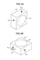
Figs. 4A and 4B are perspective views of a speaker according to the embodiment; -
Figs. 5A and 5B are perspective views of a speaker holder according to the embodiment; -
Fig. 6 is a perspective view of an elastic part according to the embodiment; -
Figs. 7A to 7C are diagrams for explaining the order in which a speaker unit is assembled according to the embodiment; -
Figs. 8A and 8B are views for explaining the order in which the speaker unit is assembled according to the embodiment; -
Figs. 9A and 9B are diagrams for explaining the order in which the speaker unit is mounted according to the embodiment; and -
Figs. 10A and 10B are diagrams illustrating the positional relation between the speaker unit and an air inlet according to the embodiment. - An embodiment will be described in which an electronic device of the present invention is applied to a projector (an image projection apparatus) with reference to the accompanying drawings. The present invention can also be applied to other electronic devices that include a speaker and need suppression of vibration of the speaker, such as a personal computer and a television set.
Fig. 1 is a perspective view of a projector 1 andFig. 2 is a perspective view of the projector 1 in a state in which anupper cover 2 is removed. - As illustrated in
Figs. 1 and2 , aprojector lens 3 is provided on theupper cover 2. Theprojector lens 3 is capable of changing magnification of image data finally projected on a projection surface. In amain unit 10 included in the housing of the projector 1, anoptical device 20, alight source device 30, aspeaker unit 40, ahousing unit 50, and anair inlet 60 are provided. -
Fig. 3 is a cross-sectional view illustrating the detailed structure of theoptical device 20 and thelight source device 30. As illustrated inFig. 3 , theoptical device 20 includes anillumination mechanism 20a and aprojecting mechanism 20b. The main unit of theoptical device 20 includes acolor wheel 25, alight tunnel 26, arelay lens 27, aplane mirror 28, and aconcave mirror 29. Each of these members is provided inside the body of theoptical device 20. Theoptical device 20 also includes animage forming unit 21. Theimage forming unit 21 includes digital micromirror devices (DMDs) serving as an image forming device that forms images. - The
color wheel 25 in a disk shape converts white light emitted from thelight source device 30 into lights of red, green, and blue repeatedly in a certain unit of time and outputs the light to thelight tunnel 26. Thelight tunnel 26 has a tubular structure made of a plurality of glass plates bonded to each other, and outputs the light emitted from thecolor wheel 25 to therelay lens 27. Therelay lens 27 includes two lenses combined with each other, and concentrates the light output from thelight tunnel 26 while correcting the axial chromatic aberration of the light. Theplane mirror 28 and theconcave mirror 29 reflect the light output from therelay lens 27 and guide the light to theimage forming unit 21, thereby concentrating the light. Theimage forming unit 21 includes digital micromirror devices (DMDs) having a rectangular surface formed with a plurality of micromirrors driven in a time-division manner based on data of a moving image or a still image. The DMDs process and reflect the projected light so that predetermined image data is formed. - The
light source device 30 includes a high pressure mercury lamp as a light source. Thelight source device 30 irradiates theillumination mechanism 20a of theoptical device 20 with white light. In theillumination mechanism 20a, the white light emitted from thelight source device 30 is divided into red, green, and blue lights (RGB) and guided to theimage forming unit 21. Theimage forming unit 21 forms images according to a modulation signal and the projectingmechanism 20b magnifies the formed image and projects the magnified image. - An OFF light plate is provided in an upper portion in the vertical direction of the
image forming unit 21, that is, on the near side inFig. 3 . The OFF light plate receives unwanted light not used as a projected light L out of the light entering theimage forming unit 21. When light enters theimage forming unit 21, a plurality of micromirrors are activated by operations of the DMD in a time-division manner based on moving image data. The micromirrors reflect the light in use to theprojector lens 3 and reflect the light to be discarded to the OFF light plate. In theimage forming unit 21, the light used for a projected image is reflected to the projectingmechanism 20b, magnified through theprojector lenses 3, whereby the magnified image light is projected. - Next, the structure of the
speaker unit 40 according to the embodiment will be described in detail. Thespeaker unit 40 is structured so that aspeaker holder 420 holds aspeaker 410.Fig. 4A and 4B are perspective views of thespeaker 410 viewed from different directions andFig. 5A and 5B are perspective views of thespeaker holder 420 viewed from different directions. - As illustrated in
Fig. 4A and 4B , thespeaker 410 includes aspeaker vibration surface 411, fourbosses 412 each serving as a first mounting part, and aharness 413. Thespeaker vibration surface 411 is a part from which sound from thespeaker 410 is output. Therespective bosses 412 extend nearly vertical from the four side surfaces of thespeaker 410. Thebosses 412 can also be described as protrusions that protrude perpendicular to the speaker. Each of the protrusions can be described, for example, as being a multi-faceted prism and/or as having an elongated or stick shape. Theharness 413 is a wire that supplies electrical power to thespeaker 410. The positions where thebosses 412 are formed will be described later. - As illustrated in
Fig. 5A and 5B , the following are formed in the speaker holder 420: fourfirst slits 421 each serving as a second mounting part, and foursecond slits 422 each serving as a third mounting part. Thefirst slits 421 and thesecond slits 422 are U-shaped slits that fit to the shape of the elastic member described later. Thefirst slits 421 are formed in the four side surfaces, i.e., the up and down, right and left side surfaces of thespeaker holder 420. The positions where thefirst slits 421 are formed correspond to the positions of thebosses 412 formed on thespeaker 410. Thefirst slit 421 and thesecond slits 422 open in opposite directions from each other and are formed in a direction parallel to the direction the sound is output from the speaker 410 (i.e., perpendicular to the speaker vibration surface 411). By forming the slits in such a manner, thespeaker 410 can be supported more rigidly against the vibrations in both the front direction and the back direction. The second slits 422 are formed in the parts protruding from the right and left surfaces of thespeaker holder 420 as illustrated inFig. 5A and 5B . - A harness slit 423 is formed in the
speaker holder 420. The harness slit 423 is used for guiding theharness 413 of thespeaker 410. One of thefirst slits 421 formed adjacent to the harness slit 423 and another one of thefirst slits 421 on the opposite side are formed at point-symmetric positions to each other with respect to a central point of the line that passes through the harness slit 423 in thespeaker holder 420. -
Fig. 6 is a perspective view illustrating the structure of an elastic part that engages with the mounting parts. As illustrated inFig. 6 , anelastic part 430 serving as a first elastic part and a second elastic part includes agroove 431 and ahole 432. Thegroove 431 is formed along the circumferential direction on the outer circumferential surface of the cylindrical body of theelastic part 430, and thehole 432 is formed along the central axis of the cylindrical body of theelastic part 430. Thegroove 431 is formed preferably on the center in the height direction of the cylindrical body of theelastic part 430. Theelastic part 430 is made of a material with a high vibration absorption property such as a chloroprene rubber and a sponge. -
Figs. 7A to 7C are diagrams for explaining the order in which thespeaker 410, thespeaker holder 420, and theelastic parts 430 are assembled. As illustrated inFig. 7A , therespective bosses 412 formed on thespeaker 410 are inserted into therespective holes 432 of theelastic parts 430. Theboss 412 and thehole 432 have diameters of the size nearly equal to each other. This generates friction therebetween and thus prevents theelastic part 430 mounted on thespeaker 410 from rotating about theboss 412, whereby theboss 412 engages with thehole 432. - As illustrated in
Fig. 7B , the respective edges of thefirst slits 421 formed in thespeaker holder 420 engage with theircorresponding grooves 431 of theelastic parts 430 mounted on thespeaker 410. The size of thefirst slit 421 is slightly larger than the size of thegroove 431 of theelastic part 430. This helps fitting the respectivefirst slits 421 into thegrooves 431. The width of thegroove 431 is nearly equal to the thickness of the side surface of thespeaker holder 420, whereby the slits and the grooves engage with each other.Fig. 7C illustrates a state in which thespeaker 410 is mounted on thespeaker holder 420. -
Figs. 8A and 8B are diagrams for explaining the order in which theelastic parts 430 are mounted on thespeaker holder 420. As illustrated inFigs. 8A and 8B , therespective grooves 431 of theelastic parts 430 are fitted into the respectivesecond slits 422 of thespeaker holders 420. Theelastic part 430 here is the same member as theelastic part 430 mounted on thespeaker 410. This completes thespeaker unit 40 including thespeaker 410 and thespeaker holder 420. -
Figs. 9A and 9B are perspective views illustrating a mode in which thespeaker unit 40 is mounted on themain unit 10. In themain unit 10, two protrudingportions 51 serving as a fourth mounting part are provided. The shape of the protrudingportion 51 corresponds to that of thehole 432 of theelastic part 430. When mounting thespeaker unit 40 on themain unit 10, the respective protrudingportions 51 are firstly inserted into therespective holes 432 of theelastic parts 430 mounted on thesecond slits 422, whereby thesecond slits 422 and the protrudingportions 51 engage with each other with theelastic parts 430 interposed therebetween. In addition, two protrudingportions 53 serving as a fourth mounting part are also provided in adetachable housing unit 50. Thehousing unit 50 is mounted to thespeaker unit 40 mounted on themain unit 10 so that the respective protrudingportions 53 are inserted downward into therespective holes 432 of theelastic parts 430 mounted on thesecond slits 422. This causes thesecond slits 422 and the protrudingportions 51 to engage with each other with theelastic parts 430 interposed therebetween. In this state, thespeaker 410, thehousing unit 50, and themain unit 10 do not come into contact with each other, whereby the vibration generated by thespeaker 410 are not transmitted directly to the projector 1. -
Figs. 10A and 10B are diagrams illustrating the positional relation between anair inlet 60 and thespeaker unit 40. As illustrated inFigs. 10A and 10B , open air taken in by theair inlet 60 flows toward thespeaker unit 40. In other words, thespeaker unit 40 is provided on the downwind side of theair inlet 60. - With the mounting structure of the speaker according to the embodiment as described above, the
speaker 410 and thespeaker holder 420, and thespeaker holder 420 and themain unit 10 are respectively fixed to each other with theelastic parts 430 interposed therebetween. The vibration generated in thespeaker 410 is, therefore, absorbed in theelastic part 430 between thespeaker 410 and thespeaker holder 420, and theelastic parts 430 between thespeaker holder 420 and themain unit 10. This suppresses the vibration caused by thespeaker 410. - In addition, when mounting the
elastic parts 430 to thespeaker 410 or thespeaker holder 420, the mounting is always achieved by inserting a part of the member included in thespeaker 410 or thespeaker holder 420 into each other. This does not require a screw or other members, thereby further suppressing the vibration. - Furthermore, with the mounting structure of the speaker according to the embodiment, the
second slits 422 are formed in the parts extending from thespeaker holder 420 for the purpose of mounting thespeaker holder 420 to themain unit 10. This achieves the design of the position and the shape of the slits based on the shape of themain unit 10, thereby increasing the flexibility of the design. - Furthermore, with the mounting structure of the speaker according to the embodiment, the
first slit 421 and thesecond slit 422 of thespeaker holder 420 are formed in a direction in parallel with the direction of the sound emitted from thespeaker 410. This effectively suppresses the vibration in the direction in which the loudest sound generated by thespeaker 410 is emitted. - Furthermore, with the mounting structure of the speaker according to the embodiment, the
speaker unit 40 is provided on the downwind side of theair inlet 60. This parallels the sound stream and the air stream, thereby suppressing degradation of the sound quality of the speaker due to the intake of air. - In place of the above-described structure, another structure may be used as follows: a slit is provided on the speaker and a protruding portion is provided on the speaker holder that engage with each other with an elastic member interposed therebetween. In addition, the shape of the elastic part may be changed based on the shape of the mounting part and the material of the elastic part and may be substituted with another material as long as it is capable of absorbing the vibration.
- The present invention can provide the advantageous effect of suppressing vibration caused by a speaker.
- Although the invention has been described with respect to specific embodiments for a complete and clear disclosure, the appended claims are not to be thus limited but are to be construed as embodying all modifications and alternative constructions that may occur to one skilled in the art that fairly fall within the basic teaching herein set forth.
Claims (8)
- An electronic device comprising:a speaker;a speaker holder that holds the speaker;a main unit on which the speaker holder is mounted;a first mounting part formed on the speaker;a second mounting part formed on the speaker holder;a first elastic part that engages with both the first mounting part and the second mounting part;a third mounting part formed on the speaker holder;a fourth mounting part formed on the main unit; anda second elastic part that engages with both the third mounting part and the fourth mounting part, whereinthe speaker and the main unit are provided in such a manner as not to come into contact with each other under the condition that the first mounting part and the second mounting part engage with the first elastic part, and the third mounting part and the fourth mounting part engage with the second elastic part.
- The electronic device according to claim 1, wherein
the first mounting part has a stick shape protruding perpendicular to the speaker,
the second mounting part is a U-shaped slit formed in the speaker holder,
the first elastic part includes a cylindrical body that has
a hole formed along a central axis of the cylindrical body, and
a groove formed along a circumferential direction on an outer circumferential surface of the cylindrical body, and
the first mounting part is inserted into the hole of the first elastic part, and the second mounting part is inserted into the groove of the first elastic part. - The electronic device according to claim 1 or 2, wherein
the third mounting part is a U-shaped slit formed in the speaker holder,
the fourth mounting part has a stick shape protruding from the main unit,
the second elastic part includes a cylindrical body that has
a hole formed along a central axis of the cylindrical body, and
a groove formed along a circumferential direction on an outer circumferential surface of the cylindrical body, and
the fourth mounting part is inserted into the hole of the second elastic part, and the fourth mounting part is inserted into the groove of the second elastic part. - The electronic device according to any one of the preceding claims, wherein
the speaker holder has a wiring hole formed thereon, which serves as a guiding path for electrical wiring of the speaker, and
the second mounting part is provided on each of the side surfaces opposite to each other of the speaker holder and at point-symmetric positions to each other with respect to a central point of a line that passes through the wiring hole in the speaker holder. - The electronic device according to any one of the preceding claims, wherein
the second mounting part is a U-shaped slit formed in the speaker holder,
the third mounting part is a U-shaped slit formed in the speaker holder, and
the U-shaped slit of the second mounting part and the U-shaped slit of the third mounting part open in opposite directions from each other. - The electronic device according to any one of the preceding claims, wherein
the second mounting part is a U-shaped slit formed in the speaker holder,
the third mounting part is a U-shaped slit formed in the speaker holder, and
each of the slits of the second mounting part and the third mounting part is formed perpendicular to a surface from which sound of the speaker is emitted. - An image projection apparatus comprising:the electronic device according to any one of claims 1 to 6.
- The image projection apparatus according to claim 7, further comprising:an air inlet that takes in open air, whereinthe surface from which sound of the speaker is emitted is located on an downwind side of a stream of the open air taken by the air inlet.
Applications Claiming Priority (1)
| Application Number | Priority Date | Filing Date | Title |
|---|---|---|---|
| JP2012198928A JP6098075B2 (en) | 2012-09-10 | 2012-09-10 | Electronic equipment, image projection device |
Publications (3)
| Publication Number | Publication Date |
|---|---|
| EP2706757A2 true EP2706757A2 (en) | 2014-03-12 |
| EP2706757A3 EP2706757A3 (en) | 2016-01-20 |
| EP2706757B1 EP2706757B1 (en) | 2018-11-07 |
Family
ID=49170549
Family Applications (1)
| Application Number | Title | Priority Date | Filing Date |
|---|---|---|---|
| EP13183004.4A Not-in-force EP2706757B1 (en) | 2012-09-10 | 2013-09-04 | Electronic device and image projection apparatus |
Country Status (4)
| Country | Link |
|---|---|
| US (1) | US9128359B2 (en) |
| EP (1) | EP2706757B1 (en) |
| JP (1) | JP6098075B2 (en) |
| CN (1) | CN103686024A (en) |
Families Citing this family (4)
| Publication number | Priority date | Publication date | Assignee | Title |
|---|---|---|---|---|
| JP6631007B2 (en) * | 2015-01-07 | 2020-01-15 | 株式会社リコー | Image projection device |
| CN105242486B (en) * | 2015-10-30 | 2017-12-01 | 苏州佳世达光电有限公司 | Display device |
| CN107817645B (en) * | 2017-12-11 | 2020-11-27 | 苏州佳世达光电有限公司 | Loudspeaker module and projector |
| CN112929767B (en) * | 2019-12-06 | 2023-05-23 | 苏州佳世达光电有限公司 | Electronic device |
Citations (2)
| Publication number | Priority date | Publication date | Assignee | Title |
|---|---|---|---|---|
| JPH08116582A (en) | 1994-10-13 | 1996-05-07 | Sony Corp | Fixing structure for speaker |
| JPH1066179A (en) | 1996-08-14 | 1998-03-06 | Sony Corp | Speaker-attaching facility |
Family Cites Families (12)
| Publication number | Priority date | Publication date | Assignee | Title |
|---|---|---|---|---|
| JPH0448793A (en) | 1990-06-15 | 1992-02-18 | Sumitomo Electric Ind Ltd | Wiring board for mounting plurality of high output elements |
| KR100308042B1 (en) * | 1999-04-15 | 2001-09-26 | 구자홍 | multiple damping device for speaker system in video display appliance |
| JP2003102081A (en) * | 2001-09-21 | 2003-04-04 | Fujitsu Ltd | Structure for mounting speaker box |
| US7114810B2 (en) * | 2004-06-25 | 2006-10-03 | Hewlett-Packard Development Company, L.P. | Multimedia display device |
| KR101108299B1 (en) * | 2005-03-18 | 2012-01-25 | 엘지전자 주식회사 | Woofer speaker mounting structure for portable computer |
| JP4562586B2 (en) * | 2005-05-19 | 2010-10-13 | シャープ株式会社 | Speaker holder and electrical equipment |
| JP2006345294A (en) * | 2005-06-09 | 2006-12-21 | Toshiba Corp | Video display apparatus |
| JP5133117B2 (en) * | 2008-04-22 | 2013-01-30 | クラリオン株式会社 | Speaker mounting structure and speaker device |
| CN101854573B (en) * | 2009-03-30 | 2014-12-24 | 富准精密工业(深圳)有限公司 | Sound structure and electronic device using same |
| JP2011160319A (en) * | 2010-02-03 | 2011-08-18 | Sharp Corp | Acoustic device and display device |
| JP2012018232A (en) * | 2010-07-06 | 2012-01-26 | Sanyo Electric Co Ltd | Projection type display device and speaker device |
| JP5691304B2 (en) | 2010-09-02 | 2015-04-01 | 株式会社リコー | Conference equipment |
-
2012
- 2012-09-10 JP JP2012198928A patent/JP6098075B2/en active Active
-
2013
- 2013-08-23 US US13/974,408 patent/US9128359B2/en not_active Expired - Fee Related
- 2013-09-04 EP EP13183004.4A patent/EP2706757B1/en not_active Not-in-force
- 2013-09-09 CN CN201310408016.1A patent/CN103686024A/en active Pending
Patent Citations (2)
| Publication number | Priority date | Publication date | Assignee | Title |
|---|---|---|---|---|
| JPH08116582A (en) | 1994-10-13 | 1996-05-07 | Sony Corp | Fixing structure for speaker |
| JPH1066179A (en) | 1996-08-14 | 1998-03-06 | Sony Corp | Speaker-attaching facility |
Also Published As
| Publication number | Publication date |
|---|---|
| CN103686024A (en) | 2014-03-26 |
| JP2014053872A (en) | 2014-03-20 |
| US20140072158A1 (en) | 2014-03-13 |
| EP2706757B1 (en) | 2018-11-07 |
| JP6098075B2 (en) | 2017-03-22 |
| EP2706757A3 (en) | 2016-01-20 |
| US9128359B2 (en) | 2015-09-08 |
Similar Documents
| Publication | Publication Date | Title |
|---|---|---|
| JP6855949B2 (en) | Projection optics and projectors | |
| US9110307B2 (en) | Optical apparatus including a holding member having an opening or a cutout, and display including the optical apparatus | |
| JP4428434B2 (en) | Optical device and projector | |
| EP2706757B1 (en) | Electronic device and image projection apparatus | |
| US9482934B2 (en) | Projector | |
| US6866389B2 (en) | Optical device and projector | |
| JP2003274314A (en) | Rear projector and method for manufacturing the same | |
| US6917481B2 (en) | Structure for tightly closing light exit end of rod integrator and rod integrator holder | |
| KR100713132B1 (en) | Projector | |
| US9110360B2 (en) | Image projection apparatus | |
| US9104093B2 (en) | Illumination optical system and image projection device | |
| US20180059526A1 (en) | Optical projection apparatus and projector | |
| JP2010160305A (en) | Light source device and projector | |
| CN110320731B (en) | Multimedia device and robot | |
| JP2004205686A (en) | Housing for projector and projector equipped with the housing | |
| JP2009042506A (en) | Projector | |
| CN210199474U (en) | Multimedia device and robot | |
| CN218213760U (en) | Diffusion device, light source module and projection system | |
| FR2868552A1 (en) | Projection module for e.g. overhead projector, has lens with optical axis parallel to screen, two reference mirrors for transmitting image beam from lens towards hyperbolic convex mirror which enlarges and transmits image beam | |
| JP2013218192A (en) | Projector | |
| JP4423998B2 (en) | Optical apparatus and projector | |
| JP2018017961A (en) | projector | |
| JP2009118328A (en) | Electronic equipment and noise removal member | |
| JP2015184547A (en) | projector | |
| JP2011203623A (en) | Projector |
Legal Events
| Date | Code | Title | Description |
|---|---|---|---|
| PUAI | Public reference made under article 153(3) epc to a published international application that has entered the european phase |
Free format text: ORIGINAL CODE: 0009012 |
|
| 17P | Request for examination filed |
Effective date: 20130904 |
|
| AK | Designated contracting states |
Kind code of ref document: A2 Designated state(s): AL AT BE BG CH CY CZ DE DK EE ES FI FR GB GR HR HU IE IS IT LI LT LU LV MC MK MT NL NO PL PT RO RS SE SI SK SM TR |
|
| AX | Request for extension of the european patent |
Extension state: BA ME |
|
| PUAL | Search report despatched |
Free format text: ORIGINAL CODE: 0009013 |
|
| AK | Designated contracting states |
Kind code of ref document: A3 Designated state(s): AL AT BE BG CH CY CZ DE DK EE ES FI FR GB GR HR HU IE IS IT LI LT LU LV MC MK MT NL NO PL PT RO RS SE SI SK SM TR |
|
| AX | Request for extension of the european patent |
Extension state: BA ME |
|
| RIC1 | Information provided on ipc code assigned before grant |
Ipc: G03B 21/14 20060101ALI20151215BHEP Ipc: H04R 1/28 20060101AFI20151215BHEP Ipc: H04R 1/02 20060101ALN20151215BHEP |
|
| REG | Reference to a national code |
Ref country code: DE Ref legal event code: R079 Ref document number: 602013046227 Country of ref document: DE Free format text: PREVIOUS MAIN CLASS: H04R0001020000 Ipc: H04R0001280000 |
|
| GRAP | Despatch of communication of intention to grant a patent |
Free format text: ORIGINAL CODE: EPIDOSNIGR1 |
|
| STAA | Information on the status of an ep patent application or granted ep patent |
Free format text: STATUS: GRANT OF PATENT IS INTENDED |
|
| RIC1 | Information provided on ipc code assigned before grant |
Ipc: H04R 1/02 20060101ALN20180405BHEP Ipc: G03B 21/14 20060101ALI20180405BHEP Ipc: H04R 1/28 20060101AFI20180405BHEP |
|
| INTG | Intention to grant announced |
Effective date: 20180417 |
|
| GRAS | Grant fee paid |
Free format text: ORIGINAL CODE: EPIDOSNIGR3 |
|
| GRAA | (expected) grant |
Free format text: ORIGINAL CODE: 0009210 |
|
| STAA | Information on the status of an ep patent application or granted ep patent |
Free format text: STATUS: THE PATENT HAS BEEN GRANTED |
|
| AK | Designated contracting states |
Kind code of ref document: B1 Designated state(s): AL AT BE BG CH CY CZ DE DK EE ES FI FR GB GR HR HU IE IS IT LI LT LU LV MC MK MT NL NO PL PT RO RS SE SI SK SM TR |
|
| REG | Reference to a national code |
Ref country code: GB Ref legal event code: FG4D |
|
| REG | Reference to a national code |
Ref country code: CH Ref legal event code: EP Ref country code: AT Ref legal event code: REF Ref document number: 1063525 Country of ref document: AT Kind code of ref document: T Effective date: 20181115 |
|
| REG | Reference to a national code |
Ref country code: IE Ref legal event code: FG4D |
|
| REG | Reference to a national code |
Ref country code: DE Ref legal event code: R096 Ref document number: 602013046227 Country of ref document: DE |
|
| REG | Reference to a national code |
Ref country code: NL Ref legal event code: MP Effective date: 20181107 |
|
| REG | Reference to a national code |
Ref country code: LT Ref legal event code: MG4D |
|
| REG | Reference to a national code |
Ref country code: AT Ref legal event code: MK05 Ref document number: 1063525 Country of ref document: AT Kind code of ref document: T Effective date: 20181107 |
|
| PG25 | Lapsed in a contracting state [announced via postgrant information from national office to epo] |
Ref country code: FI Free format text: LAPSE BECAUSE OF FAILURE TO SUBMIT A TRANSLATION OF THE DESCRIPTION OR TO PAY THE FEE WITHIN THE PRESCRIBED TIME-LIMIT Effective date: 20181107 Ref country code: BG Free format text: LAPSE BECAUSE OF FAILURE TO SUBMIT A TRANSLATION OF THE DESCRIPTION OR TO PAY THE FEE WITHIN THE PRESCRIBED TIME-LIMIT Effective date: 20190207 Ref country code: HR Free format text: LAPSE BECAUSE OF FAILURE TO SUBMIT A TRANSLATION OF THE DESCRIPTION OR TO PAY THE FEE WITHIN THE PRESCRIBED TIME-LIMIT Effective date: 20181107 Ref country code: LV Free format text: LAPSE BECAUSE OF FAILURE TO SUBMIT A TRANSLATION OF THE DESCRIPTION OR TO PAY THE FEE WITHIN THE PRESCRIBED TIME-LIMIT Effective date: 20181107 Ref country code: LT Free format text: LAPSE BECAUSE OF FAILURE TO SUBMIT A TRANSLATION OF THE DESCRIPTION OR TO PAY THE FEE WITHIN THE PRESCRIBED TIME-LIMIT Effective date: 20181107 Ref country code: ES Free format text: LAPSE BECAUSE OF FAILURE TO SUBMIT A TRANSLATION OF THE DESCRIPTION OR TO PAY THE FEE WITHIN THE PRESCRIBED TIME-LIMIT Effective date: 20181107 Ref country code: IS Free format text: LAPSE BECAUSE OF FAILURE TO SUBMIT A TRANSLATION OF THE DESCRIPTION OR TO PAY THE FEE WITHIN THE PRESCRIBED TIME-LIMIT Effective date: 20190307 Ref country code: NO Free format text: LAPSE BECAUSE OF FAILURE TO SUBMIT A TRANSLATION OF THE DESCRIPTION OR TO PAY THE FEE WITHIN THE PRESCRIBED TIME-LIMIT Effective date: 20190207 Ref country code: AT Free format text: LAPSE BECAUSE OF FAILURE TO SUBMIT A TRANSLATION OF THE DESCRIPTION OR TO PAY THE FEE WITHIN THE PRESCRIBED TIME-LIMIT Effective date: 20181107 |
|
| PG25 | Lapsed in a contracting state [announced via postgrant information from national office to epo] |
Ref country code: AL Free format text: LAPSE BECAUSE OF FAILURE TO SUBMIT A TRANSLATION OF THE DESCRIPTION OR TO PAY THE FEE WITHIN THE PRESCRIBED TIME-LIMIT Effective date: 20181107 Ref country code: PT Free format text: LAPSE BECAUSE OF FAILURE TO SUBMIT A TRANSLATION OF THE DESCRIPTION OR TO PAY THE FEE WITHIN THE PRESCRIBED TIME-LIMIT Effective date: 20190307 Ref country code: NL Free format text: LAPSE BECAUSE OF FAILURE TO SUBMIT A TRANSLATION OF THE DESCRIPTION OR TO PAY THE FEE WITHIN THE PRESCRIBED TIME-LIMIT Effective date: 20181107 Ref country code: RS Free format text: LAPSE BECAUSE OF FAILURE TO SUBMIT A TRANSLATION OF THE DESCRIPTION OR TO PAY THE FEE WITHIN THE PRESCRIBED TIME-LIMIT Effective date: 20181107 Ref country code: GR Free format text: LAPSE BECAUSE OF FAILURE TO SUBMIT A TRANSLATION OF THE DESCRIPTION OR TO PAY THE FEE WITHIN THE PRESCRIBED TIME-LIMIT Effective date: 20190208 Ref country code: SE Free format text: LAPSE BECAUSE OF FAILURE TO SUBMIT A TRANSLATION OF THE DESCRIPTION OR TO PAY THE FEE WITHIN THE PRESCRIBED TIME-LIMIT Effective date: 20181107 |
|
| PG25 | Lapsed in a contracting state [announced via postgrant information from national office to epo] |
Ref country code: CZ Free format text: LAPSE BECAUSE OF FAILURE TO SUBMIT A TRANSLATION OF THE DESCRIPTION OR TO PAY THE FEE WITHIN THE PRESCRIBED TIME-LIMIT Effective date: 20181107 Ref country code: IT Free format text: LAPSE BECAUSE OF FAILURE TO SUBMIT A TRANSLATION OF THE DESCRIPTION OR TO PAY THE FEE WITHIN THE PRESCRIBED TIME-LIMIT Effective date: 20181107 Ref country code: PL Free format text: LAPSE BECAUSE OF FAILURE TO SUBMIT A TRANSLATION OF THE DESCRIPTION OR TO PAY THE FEE WITHIN THE PRESCRIBED TIME-LIMIT Effective date: 20181107 Ref country code: DK Free format text: LAPSE BECAUSE OF FAILURE TO SUBMIT A TRANSLATION OF THE DESCRIPTION OR TO PAY THE FEE WITHIN THE PRESCRIBED TIME-LIMIT Effective date: 20181107 |
|
| REG | Reference to a national code |
Ref country code: DE Ref legal event code: R097 Ref document number: 602013046227 Country of ref document: DE |
|
| PG25 | Lapsed in a contracting state [announced via postgrant information from national office to epo] |
Ref country code: EE Free format text: LAPSE BECAUSE OF FAILURE TO SUBMIT A TRANSLATION OF THE DESCRIPTION OR TO PAY THE FEE WITHIN THE PRESCRIBED TIME-LIMIT Effective date: 20181107 Ref country code: SM Free format text: LAPSE BECAUSE OF FAILURE TO SUBMIT A TRANSLATION OF THE DESCRIPTION OR TO PAY THE FEE WITHIN THE PRESCRIBED TIME-LIMIT Effective date: 20181107 Ref country code: SK Free format text: LAPSE BECAUSE OF FAILURE TO SUBMIT A TRANSLATION OF THE DESCRIPTION OR TO PAY THE FEE WITHIN THE PRESCRIBED TIME-LIMIT Effective date: 20181107 Ref country code: RO Free format text: LAPSE BECAUSE OF FAILURE TO SUBMIT A TRANSLATION OF THE DESCRIPTION OR TO PAY THE FEE WITHIN THE PRESCRIBED TIME-LIMIT Effective date: 20181107 |
|
| PLBE | No opposition filed within time limit |
Free format text: ORIGINAL CODE: 0009261 |
|
| STAA | Information on the status of an ep patent application or granted ep patent |
Free format text: STATUS: NO OPPOSITION FILED WITHIN TIME LIMIT |
|
| 26N | No opposition filed |
Effective date: 20190808 |
|
| PG25 | Lapsed in a contracting state [announced via postgrant information from national office to epo] |
Ref country code: SI Free format text: LAPSE BECAUSE OF FAILURE TO SUBMIT A TRANSLATION OF THE DESCRIPTION OR TO PAY THE FEE WITHIN THE PRESCRIBED TIME-LIMIT Effective date: 20181107 |
|
| PG25 | Lapsed in a contracting state [announced via postgrant information from national office to epo] |
Ref country code: TR Free format text: LAPSE BECAUSE OF FAILURE TO SUBMIT A TRANSLATION OF THE DESCRIPTION OR TO PAY THE FEE WITHIN THE PRESCRIBED TIME-LIMIT Effective date: 20181107 |
|
| PG25 | Lapsed in a contracting state [announced via postgrant information from national office to epo] |
Ref country code: MC Free format text: LAPSE BECAUSE OF FAILURE TO SUBMIT A TRANSLATION OF THE DESCRIPTION OR TO PAY THE FEE WITHIN THE PRESCRIBED TIME-LIMIT Effective date: 20181107 |
|
| REG | Reference to a national code |
Ref country code: CH Ref legal event code: PL |
|
| PG25 | Lapsed in a contracting state [announced via postgrant information from national office to epo] |
Ref country code: IE Free format text: LAPSE BECAUSE OF NON-PAYMENT OF DUE FEES Effective date: 20190904 Ref country code: LU Free format text: LAPSE BECAUSE OF NON-PAYMENT OF DUE FEES Effective date: 20190904 Ref country code: LI Free format text: LAPSE BECAUSE OF NON-PAYMENT OF DUE FEES Effective date: 20190930 Ref country code: CH Free format text: LAPSE BECAUSE OF NON-PAYMENT OF DUE FEES Effective date: 20190930 |
|
| REG | Reference to a national code |
Ref country code: BE Ref legal event code: MM Effective date: 20190930 |
|
| PG25 | Lapsed in a contracting state [announced via postgrant information from national office to epo] |
Ref country code: BE Free format text: LAPSE BECAUSE OF NON-PAYMENT OF DUE FEES Effective date: 20190930 |
|
| PG25 | Lapsed in a contracting state [announced via postgrant information from national office to epo] |
Ref country code: CY Free format text: LAPSE BECAUSE OF FAILURE TO SUBMIT A TRANSLATION OF THE DESCRIPTION OR TO PAY THE FEE WITHIN THE PRESCRIBED TIME-LIMIT Effective date: 20181107 |
|
| PG25 | Lapsed in a contracting state [announced via postgrant information from national office to epo] |
Ref country code: MT Free format text: LAPSE BECAUSE OF FAILURE TO SUBMIT A TRANSLATION OF THE DESCRIPTION OR TO PAY THE FEE WITHIN THE PRESCRIBED TIME-LIMIT Effective date: 20181107 Ref country code: HU Free format text: LAPSE BECAUSE OF FAILURE TO SUBMIT A TRANSLATION OF THE DESCRIPTION OR TO PAY THE FEE WITHIN THE PRESCRIBED TIME-LIMIT; INVALID AB INITIO Effective date: 20130904 |
|
| PGFP | Annual fee paid to national office [announced via postgrant information from national office to epo] |
Ref country code: FR Payment date: 20210921 Year of fee payment: 9 |
|
| PGFP | Annual fee paid to national office [announced via postgrant information from national office to epo] |
Ref country code: GB Payment date: 20210920 Year of fee payment: 9 Ref country code: DE Payment date: 20210920 Year of fee payment: 9 |
|
| PG25 | Lapsed in a contracting state [announced via postgrant information from national office to epo] |
Ref country code: MK Free format text: LAPSE BECAUSE OF FAILURE TO SUBMIT A TRANSLATION OF THE DESCRIPTION OR TO PAY THE FEE WITHIN THE PRESCRIBED TIME-LIMIT Effective date: 20181107 |
|
| REG | Reference to a national code |
Ref country code: DE Ref legal event code: R119 Ref document number: 602013046227 Country of ref document: DE |
|
| GBPC | Gb: european patent ceased through non-payment of renewal fee |
Effective date: 20220904 |
|
| PG25 | Lapsed in a contracting state [announced via postgrant information from national office to epo] |
Ref country code: FR Free format text: LAPSE BECAUSE OF NON-PAYMENT OF DUE FEES Effective date: 20220930 Ref country code: DE Free format text: LAPSE BECAUSE OF NON-PAYMENT OF DUE FEES Effective date: 20230401 |
|
| PG25 | Lapsed in a contracting state [announced via postgrant information from national office to epo] |
Ref country code: GB Free format text: LAPSE BECAUSE OF NON-PAYMENT OF DUE FEES Effective date: 20220904 |