EP2706731A2 - Systems and methods for load balancing using predictive routing - Google Patents
Systems and methods for load balancing using predictive routing Download PDFInfo
- Publication number
- EP2706731A2 EP2706731A2 EP20130180157 EP13180157A EP2706731A2 EP 2706731 A2 EP2706731 A2 EP 2706731A2 EP 20130180157 EP20130180157 EP 20130180157 EP 13180157 A EP13180157 A EP 13180157A EP 2706731 A2 EP2706731 A2 EP 2706731A2
- Authority
- EP
- European Patent Office
- Prior art keywords
- measurement data
- predicted
- information
- destination
- requests
- Prior art date
- Legal status (The legal status is an assumption and is not a legal conclusion. Google has not performed a legal analysis and makes no representation as to the accuracy of the status listed.)
- Granted
Links
- 238000000034 method Methods 0.000 title claims abstract description 60
- 238000005259 measurement Methods 0.000 claims abstract description 231
- 230000015654 memory Effects 0.000 claims description 8
- 230000004044 response Effects 0.000 claims description 8
- 238000012545 processing Methods 0.000 claims description 7
- 238000009499 grossing Methods 0.000 claims description 6
- 239000000523 sample Substances 0.000 description 16
- 230000008569 process Effects 0.000 description 11
- 230000003247 decreasing effect Effects 0.000 description 7
- 230000006870 function Effects 0.000 description 3
- 238000010586 diagram Methods 0.000 description 2
- 238000013459 approach Methods 0.000 description 1
- 230000001413 cellular effect Effects 0.000 description 1
- 230000008859 change Effects 0.000 description 1
- 238000004590 computer program Methods 0.000 description 1
- 230000001934 delay Effects 0.000 description 1
- 230000000694 effects Effects 0.000 description 1
- 238000010801 machine learning Methods 0.000 description 1
- 238000012986 modification Methods 0.000 description 1
- 230000004048 modification Effects 0.000 description 1
- 238000010606 normalization Methods 0.000 description 1
- 230000003287 optical effect Effects 0.000 description 1
- 239000004065 semiconductor Substances 0.000 description 1
- 238000012546 transfer Methods 0.000 description 1
- 230000000007 visual effect Effects 0.000 description 1
Images


Classifications
-
- H—ELECTRICITY
- H04—ELECTRIC COMMUNICATION TECHNIQUE
- H04L—TRANSMISSION OF DIGITAL INFORMATION, e.g. TELEGRAPHIC COMMUNICATION
- H04L67/00—Network arrangements or protocols for supporting network services or applications
- H04L67/01—Protocols
- H04L67/10—Protocols in which an application is distributed across nodes in the network
- H04L67/1001—Protocols in which an application is distributed across nodes in the network for accessing one among a plurality of replicated servers
- H04L67/1004—Server selection for load balancing
- H04L67/1008—Server selection for load balancing based on parameters of servers, e.g. available memory or workload
-
- H—ELECTRICITY
- H04—ELECTRIC COMMUNICATION TECHNIQUE
- H04L—TRANSMISSION OF DIGITAL INFORMATION, e.g. TELEGRAPHIC COMMUNICATION
- H04L61/00—Network arrangements, protocols or services for addressing or naming
- H04L61/45—Network directories; Name-to-address mapping
- H04L61/4505—Network directories; Name-to-address mapping using standardised directories; using standardised directory access protocols
- H04L61/4511—Network directories; Name-to-address mapping using standardised directories; using standardised directory access protocols using domain name system [DNS]
-
- H—ELECTRICITY
- H04—ELECTRIC COMMUNICATION TECHNIQUE
- H04L—TRANSMISSION OF DIGITAL INFORMATION, e.g. TELEGRAPHIC COMMUNICATION
- H04L67/00—Network arrangements or protocols for supporting network services or applications
- H04L67/01—Protocols
- H04L67/10—Protocols in which an application is distributed across nodes in the network
- H04L67/1001—Protocols in which an application is distributed across nodes in the network for accessing one among a plurality of replicated servers
- H04L67/1004—Server selection for load balancing
- H04L67/1023—Server selection for load balancing based on a hash applied to IP addresses or costs
-
- H—ELECTRICITY
- H04—ELECTRIC COMMUNICATION TECHNIQUE
- H04L—TRANSMISSION OF DIGITAL INFORMATION, e.g. TELEGRAPHIC COMMUNICATION
- H04L67/00—Network arrangements or protocols for supporting network services or applications
- H04L67/01—Protocols
- H04L67/10—Protocols in which an application is distributed across nodes in the network
- H04L67/1001—Protocols in which an application is distributed across nodes in the network for accessing one among a plurality of replicated servers
- H04L67/1029—Protocols in which an application is distributed across nodes in the network for accessing one among a plurality of replicated servers using data related to the state of servers by a load balancer
-
- H—ELECTRICITY
- H04—ELECTRIC COMMUNICATION TECHNIQUE
- H04L—TRANSMISSION OF DIGITAL INFORMATION, e.g. TELEGRAPHIC COMMUNICATION
- H04L67/00—Network arrangements or protocols for supporting network services or applications
- H04L67/50—Network services
- H04L67/56—Provisioning of proxy services
Definitions
- This disclosure is generally directed to systems and methods for load balancing using predictive routing. More specifically, this disclosure is directed to systems and methods for routing requests for information based on a prediction of a future state of one or more destination servers.
- a load balancer on the network may route such requests for information to one of these destination servers on the network based on any number of considerations. For example, if a client computer makes a request for information to which each of the destination servers on the network are capable of responding, the load balancer may route the request to the destination server that the load balancer considers to have the most availability.
- the load balancer may receive measurements about the destination servers and determine how to route the requests based on these measurements. For example, probes distributed across the network may gather measurements about states at each destination server such as the traffic load, CPU load, response time, etc., and may send these measurements to the load balancer at regular intervals. The load balancer may then use these measurements to determine where to route requests for information.
- the probe measurements may not accurately represent the present state of each of the destination servers, but instead may represent some past state that has changed since it was measured by the probe.
- the measurements used by the load balancer may become stale due to the time between measurement intervals, the time it takes to propagate the measurement data from the destination server to the probe and from the probe to the load balancer, or any other delay that results in the reported measurements not reflecting the current state of the destination server.
- Disclosed embodiments are directed to methods and systems for predicting future measurement data at a destination server using past measurement data and then routing requests for information to the destination servers based on the predicted future measurement data.
- a system for routing requests for information based on predictive data includes one or more memories storing instructions, and one or more processors capable of executing the instructions to (a) receive measurement data indicative of states of each of a plurality of destination servers and (b) generate predicted measurement data values for each of the plurality of destination servers based on the retrieved measurement data.
- the predicted measurement data values may represent predicted states of each of the destination servers at a time later than a time corresponding to the received measurement data.
- the one or more processors may also be configured to (c) receive requests for information from a client computer and then to (d) route the received requests for information to one of the plurality of destination servers based on the predicted measurement data value.
- the system may include or be included in a domain name server that receives a name resolution request and resolves the name resolution request by selectively returning an address of at least one of the destination servers based on the predicted measurement data value.
- the one or more processors are further configured to resolve the name resolution request by returning addresses of two or more of the destination servers in an order that is determined based on the predicted measurement data value.
- the system may receive different types of measurement data, such as first measurement data indicative of first state criteria and second measurement data indicative of second state criteria, generate combined measurement data based on the different types of measurement data, and then use the combined measurement data to generate the predicted measurement data values for each of the plurality of destination servers.
- the different state criteria may include one or more of a traffic load on the corresponding destination server, a processing load on the corresponding destination server, a response time of the corresponding destination server, a proximity to the client computer of the corresponding destination server, and a cost of operating the corresponding destination server.
- the one or more processors are further configured to normalize first data values in the first measurement data and second data values in the second measurement data; and generate the combined measurement data using the normalized first data values and the normalized second data values.
- the one or more processors may be further configured to generate the combined measurement data as a weighted average of the normalized first data values and the normalized second data values.
- the one or more processors are further configured to generate the predicted measurement data values for each of the plurality of destination servers using an exponential smoothing technique.
- the one or more processors are further configured to generate, for each destination server, a time series using the measurement data and the predicted measurement data, calculate, for each time series, a mean value of values in the time series; and route the received requests for information to the destination server corresponding to the time series having the smallest mean value.
- the one or more processors may be further configured to calculate, for each time series, a standard deviation of values in the time series, and when two or more destination servers correspond to time series that both have the smallest mean value, route the received requests for information to the destination server corresponding to the time series, of the time series corresponding to the two or more destination servers, having the smallest standard deviation.
- the one or more processors are further configured to route the received requests for information to two or more of the plurality of destination servers such that a higher percentage of received requests for information are routed to the destination server with the lowest predicted measurement data value.
- the one or more processors are further configured to route all of the received requests for information to the destination server with the lowest predicted measurement data value.
- the one or more processors are further configured to compare, for each destination server, the predicted measurement data value to a value in the received measurement data, and route the received requests for information to one or more of the destination servers having a predicted measurement data value that is less than the received measurement data value.
- a method for routing requests for information based on predictive data may include receiving measurement data indicative of states of each of a plurality of destination servers, and generating, by one or more processors, predicted measurement data values for each of the plurality of destination servers based on the retrieved measurement data.
- the predicted measurement data values may represent predicted states of each of the destination servers at a time later than a time corresponding to the received measurement data.
- the method may also include receiving requests for information from a client computer and routing the received requests for information to one of the plurality of destination servers based on the predicted measurement data value.
- computer-readable storage devices may store program instructions that are executable by one or more processors to implement any of the methods disclosed herein.
- Fig. 1 is a diagram illustrating an exemplary system for routing requests for information based on predictive data, consistent with disclosed embodiments
- Fig. 2 is a flowchart illustrating an exemplary process that may be performed by the system of Fig. 1 ;
- Fig. 3 is a flowchart illustrating another exemplary process that may be performed by the system of Fig. 1 ;
- Fig. 4 is a flowchart illustrating yet another exemplary process that may be performed by the system of Fig. 1 ;
- Fig. 5 is a flowchart illustrating still another exemplary process that may be performed by the system of Fig. 1 .
- Disclosed embodiments provide systems and methods for predicting future measurement data at a destination server using past measurement data and routing requests for information to the destination servers based on the predicted future measurement data.
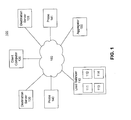
- Fig. 1 is a diagram illustrating a system 100 for routing requests for information based on predictive data.
- system 100 may include a load balancer 110, a client computer 120, destination servers 130 and 131, probes 140 and 141, and an aggregator 150 connected via a network 160.
- Network 160 may be any combination of wired and/or wireless networks, and may include, for example, any combination of local area networks (LANs), wide area networks (WANs), intranets, and the Internet.
- LANs local area networks
- WANs wide area networks
- intranets and the Internet.
- Load balancer 110 may be configured to receive requests for information from client computer 120 and route the requests for information or otherwise redirect client computer 120 to one or more of destination servers 130 and 131 based on predicted data values that are used to predict states of destination servers 130 and 131, as discussed in greater detail below. Load balancer 110 may further be configured to generate the predictive data based on measurements of data values representing the current states of destination servers 130 and 131, also discussed in greater detail below.
- load balancer 110 may include, or be included in, a name server, such as a domain name system (DNS) server.
- client computer 120 may send a request for information to load balancer 110 in the form of a DNS request, such as a request for DNS address (A) records.
- DNS domain name system
- client computer 120 may send a DNS request for example.com.
- Destination servers 130 and 131 each may host content for the requested address, example.com, but may have different internet protocol (IP) addresses.
- IP internet protocol
- load balancer 110 may return the A record of one or more of destination server 130 and destination server 131.
- load balancer 110 may determine which A record (i.e., the A record of destination server 130 or the A record of destination server 131) to return based on predicted data values, implementing one or more of the processes discussed in greater detail below.
- load balancer 110 may return the A records for both destination server 130 and destination server 131, but may determine an order or a preference ranking for each destination server based on the predicted data values, as discussed in greater detail below.
- load balancer 110 may include, or be included in, a server located, e.g., at an edge site of a content delivery network (CDN).
- client computer 120 may send a request for information to load balancer 110 in the form of a content request on the CDN.
- the content may be stored at both destination server 130 and destination server 131, for example.
- load balancer 110 may respond to the content request with a redirection command that specifies one or more of destination servers 130 and 131.
- load balancer 110 may respond to client computer 120 using a hyper text transfer protocol (HTTP) redirect that instructs computer 120 to request the content from destination 130.
- HTTP hyper text transfer protocol
- load balancer 110 may tunnel the content request to computer 120 and act as a proxy between computer 120 and destination server 130 for all or part of the remaining transaction. In these embodiments, load balancer 110 may likewise determine which destination server 130 or 131 to forward the requests to (or tunnel the requests to) based on predicted data values, in accordance with one or more embodiments discussed below.
- client computer 120 may include any type of computing device capable of sending requests for information via network 160.
- client computer 120 may include any combination of desktop or laptop computer, cellular telephone, smartphone, tablet, etc., that may make DNS or content requests to load balancer 110.
- Fig. 1 illustrates only one client computer 120, those skilled in the art will appreciate that any number of client computers 120 may be included on network 160. For example, if network 160 includes the Internet, billions of client computers may be included in system 100.
- Probes 140 and 141 may collect measurement data regarding the states of destination servers 130 and 131, respectively. For example, probes 140 and 141 may collect information related to one or more of a traffic load on the corresponding destination server, a processing load on the corresponding destination server, a response time of the corresponding destination server, a proximity to the client computer of the corresponding destination server, a cost of operating the corresponding destination server, etc. Of course, any other data measuring the states of destination servers 130 and 131 may be used.
- Probes 140 and 141 may send the measurement data to aggregator 150, e.g., at predetermined intervals.
- Aggregator 150 may aggregate the measurement data received from probes 140 and 141 on network 160 and may send the aggregated measurement data to load balancer 110.
- aggregator 150 may not be included in system 100 and/or may be included in load balancer 110 and load balancer 110 may receive the individually measured measurement data from each of probes 140 and 141.
- system 100 may include multiple load balancers distributed across network 160.
- load balancer 110 is a DNS server
- multiple load balancers may be distributed across different geographic locations.
- the multiple load balancers may have anycasted and/or multicasted IP addresses, such that requests for information from client computers located in various locations are sent to different load balancers 110, e.g., based on proximity or other factors.
- Fig. 1 only shows two destination servers 130 and 131 and two probes 140 and 141
- any number of destination servers and probes may be included in system 100.
- multiple destination servers may be included in system 100 and located in various geographic locations.
- Load balancer 110 may determine which destination server(s) to route the requests for information to, a percentage of requests to route to each destination server, and/or the order of the destination servers in which the requests should be routed, consistent with disclosed embodiments.
- load balancer 110 may include a processor 111, a storage 112, a memory 113, and one or more input/output ports 114.
- Processor 111 may include one or more processing devices, such as one or more microprocessors and/or embedded controllers, such as a microprocessor from the PentiumTM or XeonTM family manufactured by IntelTM, the TurionTM family manufactured by AMDTM, any of various processors manufactured by Sun Microsystems, or any other type of processor.
- Storage 112 may include a volatile or non-volatile, magnetic, semiconductor, tape, optical, removable, nonremovable, or other type of computer-readable medium or computer-readable storage device.
- Storage 112 may store programs and/or other information, such as one or more predictive routing programs and any other information used to determine predicted measurement data regarding destination servers 130 and 131 and route received requests for information based on the predicted measurement data, as discussed in greater detail below.
- Memory 113 may include one or more storage devices configured to store information used by load balancer 110 to perform certain functions related to disclosed embodiments.
- memory 113 may include one or more short predictive routing programs or subprograms loaded from storage 112 or elsewhere that, when executed by processor 111, perform various procedures, operations, or processes consistent with the disclosed embodiments.
- memory 113 may include one or more programs that enable load balancer 110 to, among other things, receive measurement data indicative of states of each of a plurality of destination servers, generate predicted measurement data values for each of the plurality of destination servers based on the retrieved measurement data, receive requests for information from a client computer, and route the received requests for information to one of the plurality of destination servers based on the predicted measurement data value.
- Input/output ports 114 may enable load balancer 110 to send and receive data to and from other parts of system 100 consistent with disclosed embodiments.
- load balancer 110 may receive, via input ports 114 requests for information and measurement data values and may output, via output ports 114, routing commands such as DNS responses, HTTP redirects, etc.
- load balancer 110 may perform one or more predictive routing processes, e.g., by executing one or more programs stored in memory or elsewhere.
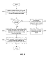
- Fig. 2 illustrates a flowchart of an exemplary predictive routing process that may be performed by load balancer 110.
- load balancer 110 may receive measurement data values corresponding to state information at a plurality of destination servers (step 210). For example, as explained above, load balancer 110 may receive measurement data values from aggregator 150 and/or from probes 140 and 141 regarding certain criteria, such as a traffic load on the corresponding destination server, a processing load on the corresponding destination server, a response time of the corresponding destination server, a proximity to the client computer of the corresponding destination server, a cost of operating the corresponding destination server, or any other type of criteria representing a state of the destination server.
- Load balancer 110 may receive the measurement data values, e.g., at predetermined intervals. Thus, while the process of Fig. 2 is shown as ending at step 260, the process may repeat at the predetermined intervals, e.g., each time the measurement data values are received.
- Load balancer 110 may also determine the number of criteria being represented in the measurement data.
- the measurement data may include measurements of two or more criteria.
- the measurement data may correspond to both the traffic load at the corresponding destination server and a cost of operating the corresponding destination server, or any other combination of two or more criteria.
- load balancer 110 may receive, as the measurement data for each destination server, a measurement data value regarding the traffic load and another measurement data value regarding the cost of operating the corresponding destination server.
- load balancer 110 may generate predicted measurement data values from the single set of measurement data values, as described in greater detail below with regard to step 250.
- load balancer 110 may further process the measurement data values, e.g., by normalizing the measurement data values for each criteria (step 230) to generate a combined measurement data value (step 240).
- Table 1 illustrates two time series of measurement data values, one for cost C and another for delay D.
- the cost C and delay D may not necessarily be measured in the same scale, and thus, if the measurement data values are merely added together, the criterion with the larger measurement data values (in this example, cost C) may have a greater effect on the routing decisions than the criterion with the smaller measurement data values.
- load balancer 110 may normalize the measurement data values, e.g., as they are received from probes 140 and 141. Load balancer 110 may normalize the measurement data values according to any statistical function that can be used to normalize data.
- load balancer 110 may receive a cost measurement data value x c and a delay measurement data value x d and may normalize each measurement data value to generate a normalized cost measurement data value x Nc and a normalized delay measurement data value x Nd , e.g., using equation (1) above.
- load balancer 110 may generate a combined measurement data value x comb .
- load balancer 110 may enable a user to determine and configure the relative weights assigned to each of the measurement data value criteria.
- load balancer 110 may generate predicted measurement data values for each of the plurality of destination servers based on the measurement data values (or the combined measurement data values, if two or more criteria exist) (step 250).
- load balancer 110 may generate the predicted measurement data values using one or more exponential smoothing methods.
- load balancer 110 may implement a Holt-Winters exponential smoothing method in double or triple exponentiation form to generate the predicted measurement data values.
- load balancer 110 may enable a user to choose the values of ⁇ and/or ⁇ .
- load balancer 110 may require initialization values for S t and b t (i.e., load balancer 110 may need to have beginning values of S and b).
- load balancer 110 may route requests for information that are received from a computer (e.g., client computer 120) based on the predicted measurement data values (step 250). Load balancer 110 may route the requests according to a variety of different methods, as discussed in greater detail below.
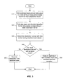
- Fig. 3 illustrates an exemplary method that may be performed by load balancer 110 to route the requests for information. This method may be performed, e.g., as part of step 250 in the method of Fig. 2 .
- load balancer 110 may generate, for each destination server, a time series using the measurement data values and the predicted measurement data values corresponding to that destination server, and may route the requests for information to the destination servers based on a statistical comparison of the time series for each destination server.
- load balancer 110 may generate a time series ⁇ x a1 , x a2 , x a3 ⁇ for destination sever 130 and a time series ⁇ x b1 , x b2 , x b3 ⁇ for destination server 131. While a time series of only three times is shown for exemplary purposes, load balancer 110 may generate time series of any length.
- Load balancer 110 may also calculate the mean and standard deviation of the time series for each destination server (step 320), and may determine the destination server with the time series having the smallest mean (step 330). If load balancer 110 determines that only one destination server has the smallest mean (step 340, N), then load balancer 110 may route the received requests for information to the destination server having the smallest mean (step 350).
- load balancer 110 may route the received requests for information to the destination server, chosen from the destination servers having the time series with the same smallest mean, that has the time series with the smallest standard deviation (step 360).
- Fig. 4 illustrates another exemplary method that may be performed by load balancer 110 to route the requests for information. This method may be performed, e.g., as part of step 250 in the method of Fig. 2 . According to the method of Fig. 4 , load balancer 110 may route the received requests for information to multiple destination servers such that a higher percentage of received requests for information are routed to the destination server with the lowest predicted measurement data value.
- load balancer 110 may determine the destination server with the lowest predicted measurement data value (step 410). As discussed above, load balancer 110 may calculate predicted measurement data values for each of the destination servers. Thus, at step 410, load balancer 110 may compare the predicted measurement data values of each destination server for a particular time interval to determine the destination sever with the lowest predicted measurement data value.
- Load balancer 110 may route a higher percentage of requests for information to the destination server having the lowest predicted measurement data value (step 420). In certain embodiments, the percentage may be set to a constant value. For example, if three destination servers exist, then load balancer 110 may route y% of the requests to the destination server having the lowest predicted measurement data value and z% of the requests to each of the remaining destination servers, such that y > z. Load balancer 110 may enable a user to configure the relationship between y and z. Moreover, in other embodiments, the relationship between y and z may be proportional to the relationship between the lowest predicted measurement data value and one or more of the remaining predicted measurement data values. For example, if the lowest predicted measurement data value is half the amount of the next lowest predicted measurement data value, then y may be twice as much as z. Of course, other methods may be used to determine the relationship between y and z.
- load balancer 110 may again recalculate the predicated measurement data values for each destination server and may again determine the destination server with the lowest predicted measurement data value (step 430). For example, because at step 420 the load balancer 110 routed a greater percentage of requests to the destination server with the lowest predicted value, the predicted measurement data values of each of the destination servers may change and the destination server that previously had the lowest predicted measurement data value may not currently have the lowest predicted measurement data value.
- load balancer 110 may increase the percentage of requests routed to the same destination server (step 450). Assume, for example, that the measurement data value applies to a single criterion of delay D. If at step 440, load balancer 110 determines that the same server that previously had the lowest delay still has the lowest delay, even after a higher percentage of requests were routed to that server in step 420, then load balancer 110 may assume that this destination server can handle an even higher number of requests for information and may thus further increase the percentage of requests sent to this server.
- the amount by which the percentage increases may be set to a constant value, may be configured by a user, and/or may be determined in any other manner.
- load balancer 110 may return to step 420 where load balancer 110 may route a higher percentage of requests to the destination server that now has the lowest predicted measurement data value. For example, the difference in percentages of requests that are routed to the different destination servers may be determined as discussed above with regard to step 420.
- Fig. 5 illustrates yet another exemplary method that may be performed by load balancer 110 to route the requests for information.
- Load balancer 110 may compare the predicted measurement data value to the last received measurement data value (step 510). Based on the comparison, load balancer 110 may determine whether the measurement data values for each destination server are increasing or decreasing (step 520). For example, if the predicted measurement data value is less than the last received measurement data value for a particular destination server, then load balancer 110 may determine that the measurement data values for that destination server are decreasing. On the other hand, if the predicted measurement data value is greater than the last received measurement data value for a particular destination server, then load balancer 110 may determine that the measurement data values for that destination server are increasing.
- Load balancer 110 may route traffic to one or more of the destination servers with decreasing measurement data values (step 530). Load balancer 110 may do this in a variety of ways. In one embodiment, load balancer 110 may route all of the received requests for information to the server that is decreasing by the greatest amount (e.g., the server that has a predicted measurement data value that is less than the corresponding last received measurement data value by the largest amount). In another embodiment, load balancer 110 may route the received requests for information to all servers that have decreasing measurement data values of any amount, e.g., by routing the requests equally among those servers, or by routing the requests proportionally to the amount by which the measurement data values are decreasing. In yet another embodiment, load balancer 110 may determine that the predicted measurement data values are not decreasing for any of the destination servers. In this case, load balancer 110 may route the requests for information to the least increasing destination server.
- load balancer 110 may route the requests for information to the least increasing destination server.
- load balancer 110 may route the requests for information based on the predicted measurement data values in other ways. For example, in one embodiment, load balancer 110 may compare the predicted measurement data value of each destination server and may route all of the requests for information to the destination server with the lowest predicted measurement data value. In another embodiment, load balancer 110 may route percentages of the requests for information to the destination servers, such that the percentages are proportional to the measurement data values.
- the measurement data values may be adjusted so that higher measurement data values correspond to a better state of the corresponding destination server.
- routing decisions as described in Figs. 3-5 , may be changed accordingly. For example, in Fig. 3 , the requests for information may be routed to the destination server with the largest mean. Likewise, in Fig. 4 , a higher percentage of the requests for information may be routed to the destination server with the highest predicted value.
- aspects are described as being stored in a memory on a computer, one skilled in the art will appreciate that these aspects can also be stored on other types of computer-readable storage media, such as secondary storage devices, like hard disks, floppy disks, a CD-ROM, USB media, DVD, or other forms of RAM or ROM.
- secondary storage devices like hard disks, floppy disks, a CD-ROM, USB media, DVD, or other forms of RAM or ROM.
- Programs based on the written description and disclosed methods are within the skill of an experienced developer.
- the various programs or program modules can be created using any of the techniques known to one skilled in the art or can be designed in connection with existing software.
- program sections or program modules can be designed in or by means of .Net Framework, .Net Compact Framework (and related languages, such as Visual Basic, C, etc.), XML, Java, C++, JavaScript, HTML, HTML/AJAX, Flex, Silverlight, or any other now known or later created programming language.
- One or more of such software sections or modules can be integrated into a computer system or existing browser software.
Abstract
Description
- This disclosure is generally directed to systems and methods for load balancing using predictive routing. More specifically, this disclosure is directed to systems and methods for routing requests for information based on a prediction of a future state of one or more destination servers.
- Companies often employ multiple destination servers on a network, each equally capable of responding to requests for information. Generally, a load balancer on the network may route such requests for information to one of these destination servers on the network based on any number of considerations. For example, if a client computer makes a request for information to which each of the destination servers on the network are capable of responding, the load balancer may route the request to the destination server that the load balancer considers to have the most availability.
- The load balancer may receive measurements about the destination servers and determine how to route the requests based on these measurements. For example, probes distributed across the network may gather measurements about states at each destination server such as the traffic load, CPU load, response time, etc., and may send these measurements to the load balancer at regular intervals. The load balancer may then use these measurements to determine where to route requests for information.
- Various delays inherent in the network, however, may cause these measurements to be stale by the time they are used by the load balancer. That is, the probe measurements (e.g., traffic load, CPU load, response time, etc.) may not accurately represent the present state of each of the destination servers, but instead may represent some past state that has changed since it was measured by the probe. For example, the measurements used by the load balancer may become stale due to the time between measurement intervals, the time it takes to propagate the measurement data from the destination server to the probe and from the probe to the load balancer, or any other delay that results in the reported measurements not reflecting the current state of the destination server.
- Thus, conventional load balancing systems may not be able to properly, or at least optimally, route requests for information to two or more destination servers because the measurements used to determine how the requests are being routed may not reflect the current state of the destination servers. One way to reduce the problem of stale data is to make measurements at more frequent time intervals. This approach, however, may increase the load on the destination servers and may be computationally expensive for both the probes and the load balancers. Thus, another way is needed to effectively route requests using the load balancer that does not increase the load on the destination servers, while still ensuring that the measurement data being used by the load balancers is not stale.
- Disclosed embodiments are directed to methods and systems for predicting future measurement data at a destination server using past measurement data and then routing requests for information to the destination servers based on the predicted future measurement data.
- In certain embodiments, a system for routing requests for information based on predictive data is disclosed that includes one or more memories storing instructions, and one or more processors capable of executing the instructions to (a) receive measurement data indicative of states of each of a plurality of destination servers and (b) generate predicted measurement data values for each of the plurality of destination servers based on the retrieved measurement data. The predicted measurement data values may represent predicted states of each of the destination servers at a time later than a time corresponding to the received measurement data. The one or more processors may also be configured to (c) receive requests for information from a client computer and then to (d) route the received requests for information to one of the plurality of destination servers based on the predicted measurement data value.
- In some embodiments, the system may include or be included in a domain name server that receives a name resolution request and resolves the name resolution request by selectively returning an address of at least one of the destination servers based on the predicted measurement data value.
- In some embodiments, the one or more processors are further configured to resolve the name resolution request by returning addresses of two or more of the destination servers in an order that is determined based on the predicted measurement data value.
- In other embodiments, the system may receive different types of measurement data, such as first measurement data indicative of first state criteria and second measurement data indicative of second state criteria, generate combined measurement data based on the different types of measurement data, and then use the combined measurement data to generate the predicted measurement data values for each of the plurality of destination servers. For example, the different state criteria may include one or more of a traffic load on the corresponding destination server, a processing load on the corresponding destination server, a response time of the corresponding destination server, a proximity to the client computer of the corresponding destination server, and a cost of operating the corresponding destination server.
- In other embodiments, the one or more processors are further configured to normalize first data values in the first measurement data and second data values in the second measurement data; and generate the combined measurement data using the normalized first data values and the normalized second data values.
- In a variant, the one or more processors may be further configured to generate the combined measurement data as a weighted average of the normalized first data values and the normalized second data values.
- In other embodiments, the one or more processors are further configured to generate the predicted measurement data values for each of the plurality of destination servers using an exponential smoothing technique.
- In other embodiments, the one or more processors are further configured to generate, for each destination server, a time series using the measurement data and the predicted measurement data, calculate, for each time series, a mean value of values in the time series; and route the received requests for information to the destination server corresponding to the time series having the smallest mean value.
- In a variant, the one or more processors may be further configured to calculate, for each time series, a standard deviation of values in the time series, and when two or more destination servers correspond to time series that both have the smallest mean value, route the received requests for information to the destination server corresponding to the time series, of the time series corresponding to the two or more destination servers, having the smallest standard deviation.
- In other embodiments, the one or more processors are further configured to route the received requests for information to two or more of the plurality of destination servers such that a higher percentage of received requests for information are routed to the destination server with the lowest predicted measurement data value.
- In some embodiments, the one or more processors are further configured to route all of the received requests for information to the destination server with the lowest predicted measurement data value.
- In other embodiments, the one or more processors are further configured to compare, for each destination server, the predicted measurement data value to a value in the received measurement data, and route the received requests for information to one or more of the destination servers having a predicted measurement data value that is less than the received measurement data value.
- In still other embodiments, a method for routing requests for information based on predictive data is disclosed. The method may include receiving measurement data indicative of states of each of a plurality of destination servers, and generating, by one or more processors, predicted measurement data values for each of the plurality of destination servers based on the retrieved measurement data. The predicted measurement data values may represent predicted states of each of the destination servers at a time later than a time corresponding to the received measurement data. The method may also include receiving requests for information from a client computer and routing the received requests for information to one of the plurality of destination servers based on the predicted measurement data value.
- Consistent with yet other disclosed embodiments, computer-readable storage devices may store program instructions that are executable by one or more processors to implement any of the methods disclosed herein.
- Additional objects and advantages of disclosed embodiments will be set forth in part in the description which follows, and in part will be obvious from the description, or may be learned by practice of the disclosed embodiments. The objects and advantages of the disclosed embodiments will be realized and attained by means of the elements and combinations particularly pointed out in the appended claims.
- It is to be understood that both the foregoing general description and the following detailed description are exemplary and explanatory only and are not restrictive of the disclosed embodiments, as claimed.
- The accompanying drawings, which are incorporated in and constitute a part of this specification, illustrate several embodiments and together with the description, serve to explain the principles of the disclosed embodiments. In the drawings:
-
Fig. 1 is a diagram illustrating an exemplary system for routing requests for information based on predictive data, consistent with disclosed embodiments; -
Fig. 2 is a flowchart illustrating an exemplary process that may be performed by the system ofFig. 1 ; -
Fig. 3 is a flowchart illustrating another exemplary process that may be performed by the system ofFig. 1 ; -
Fig. 4 is a flowchart illustrating yet another exemplary process that may be performed by the system ofFig. 1 ; and -
Fig. 5 is a flowchart illustrating still another exemplary process that may be performed by the system ofFig. 1 . - Disclosed embodiments provide systems and methods for predicting future measurement data at a destination server using past measurement data and routing requests for information to the destination servers based on the predicted future measurement data. Reference will now be made in detail to the exemplary embodiments, examples of which are illustrated in the accompanying drawings. Wherever possible, the same reference numbers will be used throughout the drawings to refer to the same or like parts.
-
Fig. 1 is a diagram illustrating asystem 100 for routing requests for information based on predictive data. As shown inFig. 1 ,system 100 may include aload balancer 110, aclient computer 120,destination servers probes aggregator 150 connected via anetwork 160.Network 160 may be any combination of wired and/or wireless networks, and may include, for example, any combination of local area networks (LANs), wide area networks (WANs), intranets, and the Internet. -
Load balancer 110 may be configured to receive requests for information fromclient computer 120 and route the requests for information or otherwise redirectclient computer 120 to one or more ofdestination servers destination servers Load balancer 110 may further be configured to generate the predictive data based on measurements of data values representing the current states ofdestination servers - In certain embodiments,
load balancer 110 may include, or be included in, a name server, such as a domain name system (DNS) server. In these embodiments,client computer 120 may send a request for information to loadbalancer 110 in the form of a DNS request, such as a request for DNS address (A) records. For example,client computer 120 may send a DNS request for example.com.Destination servers destination server 130 may correspond to IP address 1.1.1.1 whiledestination server 131 may correspond to IP address 2.2.2.2. In response to receiving the DNS request fromcomputer 120,load balancer 110 may return the A record of one or more ofdestination server 130 anddestination server 131. Moreover,load balancer 110 may determine which A record (i.e., the A record ofdestination server 130 or the A record of destination server 131) to return based on predicted data values, implementing one or more of the processes discussed in greater detail below. In one embodiment,load balancer 110 may return the A records for bothdestination server 130 anddestination server 131, but may determine an order or a preference ranking for each destination server based on the predicted data values, as discussed in greater detail below. - In other embodiments,
load balancer 110 may include, or be included in, a server located, e.g., at an edge site of a content delivery network (CDN). In these embodiments,client computer 120 may send a request for information to loadbalancer 110 in the form of a content request on the CDN. The content may be stored at bothdestination server 130 anddestination server 131, for example. In certain embodiments,load balancer 110 may respond to the content request with a redirection command that specifies one or more ofdestination servers load balancer 110 may respond toclient computer 120 using a hyper text transfer protocol (HTTP) redirect that instructscomputer 120 to request the content fromdestination 130. In other embodiments,load balancer 110 may tunnel the content request tocomputer 120 and act as a proxy betweencomputer 120 anddestination server 130 for all or part of the remaining transaction. In these embodiments,load balancer 110 may likewise determine whichdestination server - Those skilled in the art will appreciate that
client computer 120 may include any type of computing device capable of sending requests for information vianetwork 160. For example,client computer 120 may include any combination of desktop or laptop computer, cellular telephone, smartphone, tablet, etc., that may make DNS or content requests to loadbalancer 110. Moreover, whileFig. 1 illustrates only oneclient computer 120, those skilled in the art will appreciate that any number ofclient computers 120 may be included onnetwork 160. For example, ifnetwork 160 includes the Internet, billions of client computers may be included insystem 100. -
Probes destination servers destination servers -
Probes aggregator 150, e.g., at predetermined intervals.Aggregator 150 may aggregate the measurement data received fromprobes network 160 and may send the aggregated measurement data to loadbalancer 110. In certain embodiments,aggregator 150 may not be included insystem 100 and/or may be included inload balancer 110 andload balancer 110 may receive the individually measured measurement data from each ofprobes - While
Fig. 1 shows only oneload balancer 110,system 100 may include multiple load balancers distributed acrossnetwork 160. In certain embodiments, such as, for example whereload balancer 110 is a DNS server, multiple load balancers may be distributed across different geographic locations. In one embodiment, the multiple load balancers may have anycasted and/or multicasted IP addresses, such that requests for information from client computers located in various locations are sent todifferent load balancers 110, e.g., based on proximity or other factors. - Likewise, while
Fig. 1 only shows twodestination servers probes system 100. For example, multiple destination servers may be included insystem 100 and located in various geographic locations.Load balancer 110 may determine which destination server(s) to route the requests for information to, a percentage of requests to route to each destination server, and/or the order of the destination servers in which the requests should be routed, consistent with disclosed embodiments. - As shown in
Fig. 1 ,load balancer 110 may include aprocessor 111, astorage 112, amemory 113, and one or more input/output ports 114.Processor 111 may include one or more processing devices, such as one or more microprocessors and/or embedded controllers, such as a microprocessor from the Pentium™ or Xeon™ family manufactured by Intel™, the Turion™ family manufactured by AMD™, any of various processors manufactured by Sun Microsystems, or any other type of processor.Storage 112 may include a volatile or non-volatile, magnetic, semiconductor, tape, optical, removable, nonremovable, or other type of computer-readable medium or computer-readable storage device.Storage 112 may store programs and/or other information, such as one or more predictive routing programs and any other information used to determine predicted measurement data regardingdestination servers Memory 113 may include one or more storage devices configured to store information used byload balancer 110 to perform certain functions related to disclosed embodiments. - In one embodiment,
memory 113 may include one or more short predictive routing programs or subprograms loaded fromstorage 112 or elsewhere that, when executed byprocessor 111, perform various procedures, operations, or processes consistent with the disclosed embodiments. For example,memory 113 may include one or more programs that enableload balancer 110 to, among other things, receive measurement data indicative of states of each of a plurality of destination servers, generate predicted measurement data values for each of the plurality of destination servers based on the retrieved measurement data, receive requests for information from a client computer, and route the received requests for information to one of the plurality of destination servers based on the predicted measurement data value. - Input/
output ports 114 may enableload balancer 110 to send and receive data to and from other parts ofsystem 100 consistent with disclosed embodiments. For example,load balancer 110 may receive, viainput ports 114 requests for information and measurement data values and may output, viaoutput ports 114, routing commands such as DNS responses, HTTP redirects, etc. - As discussed above,
load balancer 110 may perform one or more predictive routing processes, e.g., by executing one or more programs stored in memory or elsewhere.Fig. 2 illustrates a flowchart of an exemplary predictive routing process that may be performed byload balancer 110. - As shown in
Fig. 2 ,load balancer 110 may receive measurement data values corresponding to state information at a plurality of destination servers (step 210). For example, as explained above,load balancer 110 may receive measurement data values fromaggregator 150 and/or fromprobes Load balancer 110 may receive the measurement data values, e.g., at predetermined intervals. Thus, while the process ofFig. 2 is shown as ending atstep 260, the process may repeat at the predetermined intervals, e.g., each time the measurement data values are received. -
Load balancer 110 may also determine the number of criteria being represented in the measurement data. In some embodiments, the measurement data may include measurements of two or more criteria. For example, the measurement data may correspond to both the traffic load at the corresponding destination server and a cost of operating the corresponding destination server, or any other combination of two or more criteria. Thus, at each predetermined interval,load balancer 110 may receive, as the measurement data for each destination server, a measurement data value regarding the traffic load and another measurement data value regarding the cost of operating the corresponding destination server. - If
load balancer 110 determines that only one criterion is represented in the measurement data values (step 220, No), then loadbalancer 110 may generate predicted measurement data values from the single set of measurement data values, as described in greater detail below with regard to step 250. - If
load balancer 110 determines that two or more criteria are included in the measurement data values (step 220, Yes), then loadbalancer 110 may further process the measurement data values, e.g., by normalizing the measurement data values for each criteria (step 230) to generate a combined measurement data value (step 240). - To illustrate these processing steps, consider the example where a first set of measurement data values are received that correspond to a cost C of a destination server transaction and a second set of measurement data values are received that correspond to a delay D of a transaction from source to destination. Table 1, shown below, illustrates two time series of measurement data values, one for cost C and another for delay D. As shown in Table 1, the cost C and delay D may not necessarily be measured in the same scale, and thus, if the measurement data values are merely added together, the criterion with the larger measurement data values (in this example, cost C) may have a greater effect on the routing decisions than the criterion with the smaller measurement data values.
Table 1 Time t=1 t=2 t=3 t=4 t=5 Min Max Cost C 75 80 85 90 90 75 90 Cost D 20 20 18 18 15 15 20 Sum 95 100 103 108 105 - Thus, in certain embodiments,
load balancer 110 may normalize the measurement data values, e.g., as they are received fromprobes Load balancer 110 may normalize the measurement data values according to any statistical function that can be used to normalize data. In one embodiment,load balancer 110 may implement a min-max normalization function such that each measurement data value is normalized according to the following equation:
where xN is the normalized measurement data value, x is the original measurement data value, a is the start of the new normalized range, b is the end of the new normalized range, A is the minimum value in a time series of measurement data values, and B is a maximum value in a time series of measurement data values. For example, at a time t,load balancer 110 may receive a cost measurement data value xc and a delay measurement data value xd and may normalize each measurement data value to generate a normalized cost measurement data value xNc and a normalized delay measurement data value xNd, e.g., using equation (1) above. - After normalizing the measurement data values,
load balancer 110 may generate a combined measurement data value xcomb. In certain embodiments, the combined measurement data value may be the sum of the normalized individual measurement data values. Continuing with the example where two measurement data values are received and normalized, the combined measurement data value may be determined to be:
- The combined measurement data value xcomb may be determined in other ways, e.g., to be the average or weighted average of the normalized measurement data values. Continuing with the above example, the combined measurement data value may be determined to be:

where wc is a weight associated with the cost measurement data values and wd is a weight associated with the delay measurement data values. In certain embodiments,load balancer 110 may enable a user to determine and configure the relative weights assigned to each of the measurement data value criteria. - After generating the combined measurement data values (step 240) or after determining that only one criterion is included in the measurement data (step 220),
load balancer 110 may generate predicted measurement data values for each of the plurality of destination servers based on the measurement data values (or the combined measurement data values, if two or more criteria exist) (step 250). - The predicted measurement data values may be generated in a variety of ways. For example, in certain embodiments,
load balancer 110 may generate the predicted measurement data values using one or more exponential smoothing methods. In one embodiment,load balancer 110 may implement a Holt-Winters exponential smoothing method in double or triple exponentiation form to generate the predicted measurement data values. For example, for a measurement data value xt measured at time t (or, if multiple measurement data value are collected representing multiple criteria, a combined measurement data value) in a series of measurement data values,load balancer 110 may generate a predicted measurement data value xt+1 for a time t+1 using the following equations:


where α is a data smoothing factor that determines the speed at which the older values in the time series are dampened and is chosen such that 0 ≤ α ≤ 1 and β is the trend smoothing factor and is chosen such that 0 ≤ β ≤ 1. In certain embodiments,load balancer 110 may enable a user to choose the values of α and/or β. - Those skilled in the art will appreciate that if
load balancer 110 generates predicted measurement data values according to equations (4)-(6) discussed above, then loadbalancer 110 may require initialization values for St and bt (i.e.,load balancer 110 may need to have beginning values of S and b). In certain embodiments,load balancer 110 may receive two or more sets of measurement data values prior to generating predicted data values and may determine the initialization values to be S1 = x1 and b1 = x2 - x1. - While a Holt Winters method is discussed above as an example, those skilled in the art will understand that other methods for predicting the measurement data values could be used, such as machine learning, moving averages, or any other predictive algorithm.
- After the predicted measurement data values are calculated,
load balancer 110 may route requests for information that are received from a computer (e.g., client computer 120) based on the predicted measurement data values (step 250).Load balancer 110 may route the requests according to a variety of different methods, as discussed in greater detail below. -
Fig. 3 illustrates an exemplary method that may be performed byload balancer 110 to route the requests for information. This method may be performed, e.g., as part ofstep 250 in the method ofFig. 2 . According to the method ofFig. 3 ,load balancer 110 may generate, for each destination server, a time series using the measurement data values and the predicted measurement data values corresponding to that destination server, and may route the requests for information to the destination servers based on a statistical comparison of the time series for each destination server. -
Load balancer 110 may generate a time series for each destination server by adding the predicted measurement data value to a time series of measurement data values for each destination server (step 310). For example, fordestination server 130,load balancer 110 may have received measurement data values xa1 and xa2 at times t = 1 and t = 2, respectively.Load balancer 110 may calculate a predicted measurement data value xa3, e.g., using one or more of the methods discussed above. Similarly,load balancer 110 may have received measurement data values xb1 and xb2 at times t = 1 and t = 2, respectively, fordestination server 131 and may calculate a predicted measurement data value xb3. Atstep 310,load balancer 110 may generate a time series {xa1, xa2, xa3} for destination sever 130 and a time series {xb1, xb2, xb3} fordestination server 131. While a time series of only three times is shown for exemplary purposes,load balancer 110 may generate time series of any length. -
Load balancer 110 may also calculate the mean and standard deviation of the time series for each destination server (step 320), and may determine the destination server with the time series having the smallest mean (step 330). Ifload balancer 110 determines that only one destination server has the smallest mean (step 340, N), then loadbalancer 110 may route the received requests for information to the destination server having the smallest mean (step 350). - If
load balancer 110 determines that two or more destination servers have the smallest mean (step 340, Y), then loadbalancer 110 may route the received requests for information to the destination server, chosen from the destination servers having the time series with the same smallest mean, that has the time series with the smallest standard deviation (step 360). -
Fig. 4 illustrates another exemplary method that may be performed byload balancer 110 to route the requests for information. This method may be performed, e.g., as part ofstep 250 in the method ofFig. 2 . According to the method ofFig. 4 ,load balancer 110 may route the received requests for information to multiple destination servers such that a higher percentage of received requests for information are routed to the destination server with the lowest predicted measurement data value. - For example,
load balancer 110 may determine the destination server with the lowest predicted measurement data value (step 410). As discussed above,load balancer 110 may calculate predicted measurement data values for each of the destination servers. Thus, atstep 410,load balancer 110 may compare the predicted measurement data values of each destination server for a particular time interval to determine the destination sever with the lowest predicted measurement data value. -
Load balancer 110 may route a higher percentage of requests for information to the destination server having the lowest predicted measurement data value (step 420). In certain embodiments, the percentage may be set to a constant value. For example, if three destination servers exist, then loadbalancer 110 may route y% of the requests to the destination server having the lowest predicted measurement data value and z% of the requests to each of the remaining destination servers, such that y > z.Load balancer 110 may enable a user to configure the relationship between y and z. Moreover, in other embodiments, the relationship between y and z may be proportional to the relationship between the lowest predicted measurement data value and one or more of the remaining predicted measurement data values. For example, if the lowest predicted measurement data value is half the amount of the next lowest predicted measurement data value, then y may be twice as much as z. Of course, other methods may be used to determine the relationship between y and z. - After
step 420,load balancer 110 may again recalculate the predicated measurement data values for each destination server and may again determine the destination server with the lowest predicted measurement data value (step 430). For example, because atstep 420 theload balancer 110 routed a greater percentage of requests to the destination server with the lowest predicted value, the predicted measurement data values of each of the destination servers may change and the destination server that previously had the lowest predicted measurement data value may not currently have the lowest predicted measurement data value. - If the destination server with the lowest predicted value at
step 430 is the same as the destination server with the lowest predicted value at step 410 (step 440, Yes), then loadbalancer 110 may increase the percentage of requests routed to the same destination server (step 450). Assume, for example, that the measurement data value applies to a single criterion of delay D. If atstep 440,load balancer 110 determines that the same server that previously had the lowest delay still has the lowest delay, even after a higher percentage of requests were routed to that server instep 420, then loadbalancer 110 may assume that this destination server can handle an even higher number of requests for information and may thus further increase the percentage of requests sent to this server. The amount by which the percentage increases may be set to a constant value, may be configured by a user, and/or may be determined in any other manner. - If
load balancer 110 determines that the destination server with the lowest predicted value atstep 430 is different than the destination server with the lowest predicted value at step 410 (step 440, No), then loadbalancer 110 may return to step 420 whereload balancer 110 may route a higher percentage of requests to the destination server that now has the lowest predicted measurement data value. For example, the difference in percentages of requests that are routed to the different destination servers may be determined as discussed above with regard to step 420. -
Fig. 5 illustrates yet another exemplary method that may be performed byload balancer 110 to route the requests for information. -
Load balancer 110 may compare the predicted measurement data value to the last received measurement data value (step 510). Based on the comparison,load balancer 110 may determine whether the measurement data values for each destination server are increasing or decreasing (step 520). For example, if the predicted measurement data value is less than the last received measurement data value for a particular destination server, then loadbalancer 110 may determine that the measurement data values for that destination server are decreasing. On the other hand, if the predicted measurement data value is greater than the last received measurement data value for a particular destination server, then loadbalancer 110 may determine that the measurement data values for that destination server are increasing. -
Load balancer 110 may route traffic to one or more of the destination servers with decreasing measurement data values (step 530).Load balancer 110 may do this in a variety of ways. In one embodiment,load balancer 110 may route all of the received requests for information to the server that is decreasing by the greatest amount (e.g., the server that has a predicted measurement data value that is less than the corresponding last received measurement data value by the largest amount). In another embodiment,load balancer 110 may route the received requests for information to all servers that have decreasing measurement data values of any amount, e.g., by routing the requests equally among those servers, or by routing the requests proportionally to the amount by which the measurement data values are decreasing. In yet another embodiment,load balancer 110 may determine that the predicted measurement data values are not decreasing for any of the destination servers. In this case,load balancer 110 may route the requests for information to the least increasing destination server. - Of course,
load balancer 110 may route the requests for information based on the predicted measurement data values in other ways. For example, in one embodiment,load balancer 110 may compare the predicted measurement data value of each destination server and may route all of the requests for information to the destination server with the lowest predicted measurement data value. In another embodiment,load balancer 110 may route percentages of the requests for information to the destination servers, such that the percentages are proportional to the measurement data values. - In the above exemplary embodiments, an assumption was made regarding the measurement data values that a lower measurement data value represents a better state of the corresponding destination server. For example, if two criteria being used are delay and processor usage, then lower delay and processor usage measurement data values correspond to a better state than higher delay and processor usage measurement data values. Those skilled in the art will appreciate, however, that in certain embodiments, the measurement data values may be adjusted so that higher measurement data values correspond to a better state of the corresponding destination server. Thus, in these embodiments, routing decisions, as described in
Figs. 3-5 , may be changed accordingly. For example, inFig. 3 , the requests for information may be routed to the destination server with the largest mean. Likewise, inFig. 4 , a higher percentage of the requests for information may be routed to the destination server with the highest predicted value. - The foregoing descriptions have been presented for purposes of illustration and description. They are not exhaustive and do not limit the disclosed embodiments to the precise form disclosed. Modifications and variations are possible in light of the above teachings or may be acquired from practicing the disclosed embodiments. For example, the described implementation includes software, but the disclosed embodiments may be implemented as a combination of hardware and software or in firmware. Examples of hardware include computing or processing systems, including personal computers, servers, laptops, mainframes, micro-processors, and the like. Additionally, although disclosed aspects are described as being stored in a memory on a computer, one skilled in the art will appreciate that these aspects can also be stored on other types of computer-readable storage media, such as secondary storage devices, like hard disks, floppy disks, a CD-ROM, USB media, DVD, or other forms of RAM or ROM.
- Computer programs based on the written description and disclosed methods are within the skill of an experienced developer. The various programs or program modules can be created using any of the techniques known to one skilled in the art or can be designed in connection with existing software. For example, program sections or program modules can be designed in or by means of .Net Framework, .Net Compact Framework (and related languages, such as Visual Basic, C, etc.), XML, Java, C++, JavaScript, HTML, HTML/AJAX, Flex, Silverlight, or any other now known or later created programming language. One or more of such software sections or modules can be integrated into a computer system or existing browser software.
- Other embodiments will be apparent to those skilled in the art from consideration of the specification and practice of the embodiments disclosed herein. The recitations in the claims are to be interpreted broadly based on the language employed in the claims and not limited to examples described in the present specification or during the prosecution of the application, which examples are to be construed non-exclusive. Further, the steps of the disclosed methods may be modified in any manner, including by reordering steps and/or inserting or deleting steps. It is intended, therefore, that the specification and examples be considered as exemplary only, with a true scope and spirit being indicated by the following claims and their full scope equivalents.
Claims (15)
- A system (100) for routing requests for information based on predictive data, the system comprising:one or more memories storing instructions; andone or more processors capable of executing the instructions to:receive measurement data indicative of states of each of a plurality of destination servers (130,131);generate predicted measurement data values for each of the plurality of destination servers based on the retrieved measurement data, the predicted measurement data values representing predicted states of each of the destination servers at a time later than a time corresponding to the received measurement data;receive requests for information from a client computer (120); androute the received requests for information to one of the plurality of destination servers based on the predicted measurement data value.
- A computer-implemented method for routing requests for information based on predictive data, the computer-implemented method comprising:receiving (210) measurement data indicative of states of each of a plurality of destination servers;generating (250), by one or more processors, predicted measurement data values for each of the plurality of destination servers based on the retrieved measurement data, the predicted measurement data values representing predicted states of each of the destination servers at a time later than a time corresponding to the received measurement data;receiving requests for information from a client computer; androuting (260) the received requests for information to one of the plurality of destination servers based on the predicted measurement data value.
- The computer-implemented method of claim 2, wherein the received requests for information are name resolution requests, the computer-implemented method further comprising:resolving the name resolution request by selectively returning an address of at least one of the destination servers based on the predicted measurement data value.
- The computer-implemented method of claim 3, further comprising:resolving the name resolution request by returning addresses of two or more of the destination servers in an order that is determined based on the predicted measurement data value.
- The computer-implemented method of claim 2, further comprising:receiving, as the measurement data, first measurement data indicative of first state criteria and second measurement data indicative of second state criteria;generating, for each of the plurality of destination servers, combined measurement data from the first measurement data and the second measurement data; andgenerating the predicted measurement data values for each of the plurality of destination servers based on the combined measurement data.
- The computer-implemented method of claim 5, wherein the first and second state criteria each include one selected from the group consisting of: a traffic load on the corresponding destination server, a processing load on the corresponding destination server, a response time of the corresponding destination server, a proximity to the client computer of the corresponding destination server, and a cost of operating the corresponding destination server.
- The computer-implemented method of claim 5, further comprising:normalizing first data values in the first measurement data and second data values in the second measurement data; andgenerating the combined measurement data using the normalized first data values and the normalized second data values.
- The computer-implemented method of claim 7, further comprising:generating the combined measurement data as a weighted average of the normalized first data values and the normalized second data values.
- The computer-implemented method of claim 2, further comprising:generating the predicted measurement data values for each of the plurality of destination servers using an exponential smoothing technique.
- The computer-implemented method of claim 2, further comprising:generating (310), for each destination server (130,131), a time series using the measurement data and the predicted measurement data;calculating (320), for each time series, a mean value of values in the time series; androuting (350,360) the received requests for information to the destination server corresponding to the time series having the smallest mean value.
- The computer-implemented method of claim 10, further comprising:calculating, for each time series, a standard deviation of values in the time series; andwhen two or more destination servers correspond to time series that both have the smallest mean value, routing the received requests for information to the destination server corresponding to the time series, of the time series corresponding to the two or more destination servers, having the smallest standard deviation.
- The computer-implemented method of claim 2, further comprising:routing (420) the received requests for information to two or more of the plurality of destination servers such that a higher percentage of received requests for information are routed to the destination server with the lowest predicted measurement data value.
- The computer-implemented method of claim 2, further comprising:routing all of the received requests for information to the destination server with the lowest predicted measurement data value.
- The computer-implemented method of claim 2, further comprising:comparing (510), for each destination server, the predicted measurement data value to a value in the received measurement data; androuting (530) the received requests for information to one or more of the destination servers having a predicted measurement data value that is less than the received measurement data value.
- A non-transitory computer readable medium comprising:instructions for routing requests for information based on predictive data that, when executed by one or more processors, enable the one or more processors to:receive measurement data indicative of states of each of a plurality of destination servers;generate predicted measurement data values for each of the plurality of destination servers based on the retrieved measurement data, the predicted measurement data values representing predicted states of each of the destination servers at a time later than a time corresponding to the received measurement data;receive requests for information from a client computer; androute the received requests for information to one of the plurality of destination servers based on the predicted measurement data value.
Applications Claiming Priority (1)
| Application Number | Priority Date | Filing Date | Title |
|---|---|---|---|
| US13/572,848 US10652318B2 (en) | 2012-08-13 | 2012-08-13 | Systems and methods for load balancing using predictive routing |
Publications (3)
| Publication Number | Publication Date |
|---|---|
| EP2706731A2 true EP2706731A2 (en) | 2014-03-12 |
| EP2706731A3 EP2706731A3 (en) | 2014-05-07 |
| EP2706731B1 EP2706731B1 (en) | 2018-04-04 |
Family
ID=48953333
Family Applications (1)
| Application Number | Title | Priority Date | Filing Date |
|---|---|---|---|
| EP13180157.3A Active EP2706731B1 (en) | 2012-08-13 | 2013-08-13 | Systems and methods for load balancing using predictive routing |
Country Status (2)
| Country | Link |
|---|---|
| US (1) | US10652318B2 (en) |
| EP (1) | EP2706731B1 (en) |
Cited By (2)
| Publication number | Priority date | Publication date | Assignee | Title |
|---|---|---|---|---|
| WO2017010922A1 (en) * | 2015-07-14 | 2017-01-19 | Telefonaktiebolaget Lm Ericsson (Publ) | Allocation of cloud computing resources |
| WO2017129992A1 (en) * | 2016-01-29 | 2017-08-03 | Tectonic Interactive Limited | System and method for managing communication sessions between clients and a server |
Families Citing this family (67)
| Publication number | Priority date | Publication date | Assignee | Title |
|---|---|---|---|---|
| US7991910B2 (en) | 2008-11-17 | 2011-08-02 | Amazon Technologies, Inc. | Updating routing information based on client location |
| US8028090B2 (en) | 2008-11-17 | 2011-09-27 | Amazon Technologies, Inc. | Request routing utilizing client location information |
| US8321568B2 (en) | 2008-03-31 | 2012-11-27 | Amazon Technologies, Inc. | Content management |
| US8447831B1 (en) | 2008-03-31 | 2013-05-21 | Amazon Technologies, Inc. | Incentive driven content delivery |
| US7962597B2 (en) | 2008-03-31 | 2011-06-14 | Amazon Technologies, Inc. | Request routing based on class |
| US7970820B1 (en) | 2008-03-31 | 2011-06-28 | Amazon Technologies, Inc. | Locality based content distribution |
| US8606996B2 (en) | 2008-03-31 | 2013-12-10 | Amazon Technologies, Inc. | Cache optimization |
| US8601090B1 (en) | 2008-03-31 | 2013-12-03 | Amazon Technologies, Inc. | Network resource identification |
| US9407681B1 (en) | 2010-09-28 | 2016-08-02 | Amazon Technologies, Inc. | Latency measurement in resource requests |
| US8073940B1 (en) | 2008-11-17 | 2011-12-06 | Amazon Technologies, Inc. | Managing content delivery network service providers |
| US8688837B1 (en) | 2009-03-27 | 2014-04-01 | Amazon Technologies, Inc. | Dynamically translating resource identifiers for request routing using popularity information |
| US8756341B1 (en) * | 2009-03-27 | 2014-06-17 | Amazon Technologies, Inc. | Request routing utilizing popularity information |
| US8412823B1 (en) | 2009-03-27 | 2013-04-02 | Amazon Technologies, Inc. | Managing tracking information entries in resource cache components |
| US8782236B1 (en) | 2009-06-16 | 2014-07-15 | Amazon Technologies, Inc. | Managing resources using resource expiration data |
| US8397073B1 (en) | 2009-09-04 | 2013-03-12 | Amazon Technologies, Inc. | Managing secure content in a content delivery network |
| US8433771B1 (en) | 2009-10-02 | 2013-04-30 | Amazon Technologies, Inc. | Distribution network with forward resource propagation |
| US9495338B1 (en) | 2010-01-28 | 2016-11-15 | Amazon Technologies, Inc. | Content distribution network |
| US10958501B1 (en) | 2010-09-28 | 2021-03-23 | Amazon Technologies, Inc. | Request routing information based on client IP groupings |
| US8468247B1 (en) | 2010-09-28 | 2013-06-18 | Amazon Technologies, Inc. | Point of presence management in request routing |
| US9003035B1 (en) | 2010-09-28 | 2015-04-07 | Amazon Technologies, Inc. | Point of presence management in request routing |
| US9712484B1 (en) | 2010-09-28 | 2017-07-18 | Amazon Technologies, Inc. | Managing request routing information utilizing client identifiers |
| US8452874B2 (en) | 2010-11-22 | 2013-05-28 | Amazon Technologies, Inc. | Request routing processing |
| US10467042B1 (en) | 2011-04-27 | 2019-11-05 | Amazon Technologies, Inc. | Optimized deployment based upon customer locality |
| US10623408B1 (en) | 2012-04-02 | 2020-04-14 | Amazon Technologies, Inc. | Context sensitive object management |
| US9154551B1 (en) | 2012-06-11 | 2015-10-06 | Amazon Technologies, Inc. | Processing DNS queries to identify pre-processing information |
| US9323577B2 (en) | 2012-09-20 | 2016-04-26 | Amazon Technologies, Inc. | Automated profiling of resource usage |
| TWI474673B (en) * | 2012-12-06 | 2015-02-21 | Inst Information Industry | Workload dispatch device and workload dispatch method thereof |
| US10205698B1 (en) | 2012-12-19 | 2019-02-12 | Amazon Technologies, Inc. | Source-dependent address resolution |
| US9773026B1 (en) * | 2012-12-20 | 2017-09-26 | EMC IP Holding Company LLC | Calculation of system utilization |
| US9294391B1 (en) | 2013-06-04 | 2016-03-22 | Amazon Technologies, Inc. | Managing network computing components utilizing request routing |
| US9407721B2 (en) * | 2013-10-16 | 2016-08-02 | Red Hat, Inc. | System and method for server selection using competitive evaluation |
| US9426215B2 (en) * | 2014-04-08 | 2016-08-23 | Aol Inc. | Determining load state of remote systems using delay and packet loss rate |
| US10091096B1 (en) | 2014-12-18 | 2018-10-02 | Amazon Technologies, Inc. | Routing mode and point-of-presence selection service |
| US10097448B1 (en) | 2014-12-18 | 2018-10-09 | Amazon Technologies, Inc. | Routing mode and point-of-presence selection service |
| US10225326B1 (en) | 2015-03-23 | 2019-03-05 | Amazon Technologies, Inc. | Point of presence based data uploading |
| US9819567B1 (en) | 2015-03-30 | 2017-11-14 | Amazon Technologies, Inc. | Traffic surge management for points of presence |
| US9832141B1 (en) | 2015-05-13 | 2017-11-28 | Amazon Technologies, Inc. | Routing based request correlation |
| US10097566B1 (en) | 2015-07-31 | 2018-10-09 | Amazon Technologies, Inc. | Identifying targets of network attacks |
| US9774619B1 (en) | 2015-09-24 | 2017-09-26 | Amazon Technologies, Inc. | Mitigating network attacks |
| US10243918B2 (en) | 2015-10-19 | 2019-03-26 | Time Warner Cable Enterprises Llc | Method and apparatus for automatic geoaware access point provisioning |
| US10270878B1 (en) | 2015-11-10 | 2019-04-23 | Amazon Technologies, Inc. | Routing for origin-facing points of presence |
| US10257307B1 (en) | 2015-12-11 | 2019-04-09 | Amazon Technologies, Inc. | Reserved cache space in content delivery networks |
| US10348639B2 (en) | 2015-12-18 | 2019-07-09 | Amazon Technologies, Inc. | Use of virtual endpoints to improve data transmission rates |
| US10094674B2 (en) * | 2016-02-16 | 2018-10-09 | Ford Global Technologies, Llc | Predictive vehicle task scheduling |
| US10552413B2 (en) * | 2016-05-09 | 2020-02-04 | Sap Se | Database workload capture and replay |
| US10075551B1 (en) | 2016-06-06 | 2018-09-11 | Amazon Technologies, Inc. | Request management for hierarchical cache |
| US10110694B1 (en) | 2016-06-29 | 2018-10-23 | Amazon Technologies, Inc. | Adaptive transfer rate for retrieving content from a server |
| US9992086B1 (en) | 2016-08-23 | 2018-06-05 | Amazon Technologies, Inc. | External health checking of virtual private cloud network environments |
| US10033691B1 (en) | 2016-08-24 | 2018-07-24 | Amazon Technologies, Inc. | Adaptive resolution of domain name requests in virtual private cloud network environments |
| US10469513B2 (en) | 2016-10-05 | 2019-11-05 | Amazon Technologies, Inc. | Encrypted network addresses |
| US10700978B2 (en) | 2016-12-05 | 2020-06-30 | International Business Machines Corporation | Offloading at a virtual switch in a load-balanced group |
| US10768997B2 (en) | 2016-12-05 | 2020-09-08 | International Business Machines Corporation | Tail latency-based job offloading in load-balanced groups |
| WO2018108250A1 (en) * | 2016-12-13 | 2018-06-21 | Abb Schweiz Ag | A multi-client/multi-server managing method and system with a routine of rejection of already connected clients for balancing the system |
| US10831549B1 (en) | 2016-12-27 | 2020-11-10 | Amazon Technologies, Inc. | Multi-region request-driven code execution system |
| US10372499B1 (en) | 2016-12-27 | 2019-08-06 | Amazon Technologies, Inc. | Efficient region selection system for executing request-driven code |
| US10938884B1 (en) | 2017-01-30 | 2021-03-02 | Amazon Technologies, Inc. | Origin server cloaking using virtual private cloud network environments |
| US10503613B1 (en) | 2017-04-21 | 2019-12-10 | Amazon Technologies, Inc. | Efficient serving of resources during server unavailability |
| US11075987B1 (en) | 2017-06-12 | 2021-07-27 | Amazon Technologies, Inc. | Load estimating content delivery network |
| US10447648B2 (en) | 2017-06-19 | 2019-10-15 | Amazon Technologies, Inc. | Assignment of a POP to a DNS resolver based on volume of communications over a link between client devices and the POP |
| US10742593B1 (en) | 2017-09-25 | 2020-08-11 | Amazon Technologies, Inc. | Hybrid content request routing system |
| US10592578B1 (en) | 2018-03-07 | 2020-03-17 | Amazon Technologies, Inc. | Predictive content push-enabled content delivery network |
| US20190319881A1 (en) * | 2018-04-13 | 2019-10-17 | Microsoft Technology Licensing, Llc | Traffic management based on past traffic arrival patterns |
| US11323465B2 (en) * | 2018-09-19 | 2022-05-03 | Nec Corporation | Temporal behavior analysis of network traffic |
| US10862852B1 (en) | 2018-11-16 | 2020-12-08 | Amazon Technologies, Inc. | Resolution of domain name requests in heterogeneous network environments |
| US11025747B1 (en) | 2018-12-12 | 2021-06-01 | Amazon Technologies, Inc. | Content request pattern-based routing system |
| US11233768B1 (en) * | 2020-09-30 | 2022-01-25 | Akamai Technologies, Inc. | CDN configuration tuning based on domain scan analysis |
| US20230055079A1 (en) * | 2021-07-30 | 2023-02-23 | Samsung Electronics Co., Ltd. | Method of load forecasting via attentive knowledge transfer, and an apparatus for the same |
Family Cites Families (82)
| Publication number | Priority date | Publication date | Assignee | Title |
|---|---|---|---|---|
| US6178160B1 (en) | 1997-12-23 | 2001-01-23 | Cisco Technology, Inc. | Load balancing of client connections across a network using server based algorithms |
| JP3769999B2 (en) | 1999-09-30 | 2006-04-26 | 富士通株式会社 | Service distribution device |
| JP2001109638A (en) * | 1999-10-06 | 2001-04-20 | Nec Corp | Method and system for distributing transaction load based on estimated extension rate and computer readable recording medium |
| US7062556B1 (en) * | 1999-11-22 | 2006-06-13 | Motorola, Inc. | Load balancing method in a communication network |
| US6560717B1 (en) | 1999-12-10 | 2003-05-06 | Art Technology Group, Inc. | Method and system for load balancing and management |
| US6950848B1 (en) * | 2000-05-05 | 2005-09-27 | Yousefi Zadeh Homayoun | Database load balancing for multi-tier computer systems |
| US7028083B2 (en) * | 2000-05-26 | 2006-04-11 | Akomai Technologies, Inc. | Method for extending a network map |
| US7096263B2 (en) * | 2000-05-26 | 2006-08-22 | Akamai Technologies, Inc. | Method for predicting file download time from mirrored data centers in a global computer network |
| US7734815B2 (en) * | 2006-09-18 | 2010-06-08 | Akamai Technologies, Inc. | Global load balancing across mirrored data centers |
| CA2450394C (en) * | 2000-05-26 | 2011-07-19 | Akamai Technologies, Inc. | Global load balancing across mirrored data centers |
| US7251688B2 (en) * | 2000-05-26 | 2007-07-31 | Akamai Technologies, Inc. | Method for generating a network map |
| US7454500B1 (en) * | 2000-09-26 | 2008-11-18 | Foundry Networks, Inc. | Global server load balancing |
| US7231445B1 (en) * | 2000-11-16 | 2007-06-12 | Nortel Networks Limited | Technique for adaptively distributing web server requests |
| US7536455B2 (en) * | 2001-03-18 | 2009-05-19 | At&T Corp. | Optimal combination of sampled measurements |
| US7080136B2 (en) * | 2001-03-18 | 2006-07-18 | At & T Corp. | Method and apparatus for size-dependent sampling for managing a data network |
| US20020188710A1 (en) * | 2001-03-18 | 2002-12-12 | At&T Corp. | Size-dependent sampling for managing a data network |
| US7818224B2 (en) * | 2001-03-22 | 2010-10-19 | Boerner Sean T | Method and system to identify discrete trends in time series |
| US7111074B2 (en) | 2001-07-24 | 2006-09-19 | Pluris, Inc. | Control method for data path load-balancing on a data packet network |
| US7187652B2 (en) * | 2001-12-26 | 2007-03-06 | Tropic Networks Inc. | Multi-constraint routing system and method |
| ES2321820T3 (en) * | 2002-11-04 | 2009-06-12 | Siemens Aktiengesellschaft | PROCEDURE AND APPLIANCE TO ACHIEVE AN OPTIMAL RESPONSE TIME IN A TELECOMMUNICATIONS SYSTEM. |
| US20040103194A1 (en) * | 2002-11-21 | 2004-05-27 | Docomo Communicatios Laboratories Usa, Inc. | Method and system for server load balancing |
| US7783759B2 (en) * | 2002-12-10 | 2010-08-24 | International Business Machines Corporation | Methods and apparatus for dynamic allocation of servers to a plurality of customers to maximize the revenue of a server farm |
| US7386611B2 (en) * | 2002-12-10 | 2008-06-10 | International Business Machines Corporation | Apparatus and methods for co-location and offloading of web site traffic based on traffic pattern recognition |
| US20040122950A1 (en) * | 2002-12-20 | 2004-06-24 | Morgan Stephen Paul | Method for managing workloads in an autonomic computer system for improved performance |
| JP4119239B2 (en) * | 2002-12-20 | 2008-07-16 | 株式会社日立製作所 | Computer resource allocation method, resource management server and computer system for executing the method |
| US7382765B2 (en) | 2003-04-30 | 2008-06-03 | Harris Corporation | Predictive routing in a moble ad hoc network |
| US7430603B2 (en) * | 2003-11-10 | 2008-09-30 | Eath Co., Ltd. | Aggregation system |
| AU2003295301A1 (en) | 2003-12-23 | 2005-07-14 | Telefonaktiebolaget Lm Ericsson (Publ) | Method and system for efficient routing in ad hoc networks |
| US20050278703A1 (en) * | 2004-06-15 | 2005-12-15 | K5 Systems Inc. | Method for using statistical analysis to monitor and analyze performance of new network infrastructure or software applications for deployment thereof |
| US8010324B1 (en) * | 2005-05-09 | 2011-08-30 | Sas Institute Inc. | Computer-implemented system and method for storing data analysis models |
| EP2216762B1 (en) | 2005-05-18 | 2011-05-11 | Lg Electronics Inc. | Providing traffic information relating to a prediction of congestion status and using the same |
| US7519734B1 (en) * | 2006-03-14 | 2009-04-14 | Amazon Technologies, Inc. | System and method for routing service requests |
| US7783510B1 (en) * | 2006-06-23 | 2010-08-24 | Quest Software, Inc. | Computer storage capacity forecasting system using cluster-based seasonality analysis |
| US20070300239A1 (en) * | 2006-06-23 | 2007-12-27 | International Business Machines Corporation | Dynamic application instance placement in data center environments |
| US8050671B2 (en) | 2006-11-03 | 2011-11-01 | Alcatel Lucent | Method and apparatus for network growth planning in wireless networks |
| US7693823B2 (en) * | 2007-06-28 | 2010-04-06 | Microsoft Corporation | Forecasting time-dependent search queries |
| US7685099B2 (en) * | 2007-06-28 | 2010-03-23 | Microsoft Corporation | Forecasting time-independent search queries |
| US7685100B2 (en) * | 2007-06-28 | 2010-03-23 | Microsoft Corporation | Forecasting search queries based on time dependencies |
| US7689622B2 (en) * | 2007-06-28 | 2010-03-30 | Microsoft Corporation | Identification of events of search queries |
| US8260940B1 (en) * | 2007-06-29 | 2012-09-04 | Amazon Technologies, Inc. | Service request management |
| US9811849B2 (en) * | 2007-09-28 | 2017-11-07 | Great-Circle Technologies, Inc. | Contextual execution of automated workflows |
| US9083722B2 (en) * | 2007-10-05 | 2015-07-14 | Qualcomm Incorporated | Session initiation protocol registration with ping |
| US8493882B2 (en) * | 2008-05-29 | 2013-07-23 | Nec Corporation | Optimization evaluation system, optimization evaluation device, optimization evaluation method, and optimization evaluation program |
| US20100030896A1 (en) * | 2008-06-19 | 2010-02-04 | Microsoft Corporation | Estimating latencies for query optimization in distributed stream processing |
| US9081624B2 (en) * | 2008-06-26 | 2015-07-14 | Microsoft Technology Licensing, Llc | Automatic load balancing, such as for hosted applications |
| US20100017239A1 (en) * | 2008-06-30 | 2010-01-21 | Eric Saltzman | Forecasting Discovery Costs Using Historic Data |
| US8948193B2 (en) | 2008-08-19 | 2015-02-03 | Check Point Software Technologies, Ltd. | Methods for intelligent NIC bonding and load-balancing |
| US8751195B2 (en) * | 2008-09-24 | 2014-06-10 | Inotera Memories, Inc. | Method for automatically shifting a base line |
| TWI380141B (en) * | 2008-09-24 | 2012-12-21 | Inotera Memories Inc | Method for automatically detecting and shifting the base line in semiconductor process |
| CN102099790B (en) * | 2008-10-30 | 2012-12-19 | 株式会社日立制作所 | Operation management apparatus of information processing system |
| US8793529B2 (en) * | 2008-11-04 | 2014-07-29 | Verizon Patent And Licensing Inc. | Congestion control method for session based network traffic |
| US8225119B2 (en) * | 2009-02-23 | 2012-07-17 | Microsoft Corporation | Energy-aware server management |
| JP5149840B2 (en) * | 2009-03-03 | 2013-02-20 | 株式会社日立製作所 | Stream data processing method, stream data processing program, and stream data processing apparatus |
| WO2010141460A1 (en) * | 2009-06-01 | 2010-12-09 | Swarmcast, Inc. | Data retrieval based on bandwidth cost and delay |
| US9323234B2 (en) * | 2009-06-10 | 2016-04-26 | Fisher-Rosemount Systems, Inc. | Predicted fault analysis |
| US8479216B2 (en) * | 2009-08-18 | 2013-07-02 | International Business Machines Corporation | Method for decentralized load distribution in an event-driven system using localized migration between physically connected nodes and load exchange protocol preventing simultaneous migration of plurality of tasks to or from a same node |
| US8479215B2 (en) * | 2009-08-18 | 2013-07-02 | International Business Machines Corporation | Decentralized load distribution to reduce power and/or cooling costs in an event-driven system |
| US8355328B2 (en) * | 2009-08-27 | 2013-01-15 | Broadcom Corporation | Dynamic load balancing |
| US20110063986A1 (en) * | 2009-09-14 | 2011-03-17 | International Business Machines Corporation | System and method for load balancing traffic in a mpls network |
| US20110153828A1 (en) * | 2009-12-17 | 2011-06-23 | Korea Advanced Institute Of Science And Technology | Load balancing apparatus and method for regulating load using the same |
| US20120020216A1 (en) * | 2010-01-15 | 2012-01-26 | Telcordia Technologies, Inc. | Cognitive network load prediction method and apparatus |
| WO2011138854A1 (en) * | 2010-05-06 | 2011-11-10 | 日本電気株式会社 | Resource management system, resource management method and resource management program |
| CA2811630C (en) * | 2010-08-24 | 2020-06-16 | Solano Labs, Inc. | Method and apparatus for clearing cloud compute demand |
| US8468247B1 (en) * | 2010-09-28 | 2013-06-18 | Amazon Technologies, Inc. | Point of presence management in request routing |
| JP5568776B2 (en) * | 2010-11-05 | 2014-08-13 | 株式会社日立製作所 | Computer monitoring system and monitoring method |
| WO2012066604A1 (en) | 2010-11-19 | 2012-05-24 | Hitachi, Ltd. | Server system and method for managing the same |
| US8499066B1 (en) * | 2010-11-19 | 2013-07-30 | Amazon Technologies, Inc. | Predicting long-term computing resource usage |
| EP2469758A1 (en) * | 2010-12-24 | 2012-06-27 | British Telecommunications Public Limited Company | Communications network management |
| EP2498540B1 (en) * | 2011-03-11 | 2013-03-06 | Alcatel Lucent | Computing cloud in a wireless telecommunication system |
| US8601483B2 (en) * | 2011-03-22 | 2013-12-03 | International Business Machines Corporation | Forecasting based service for virtual machine reassignment in computing environment |
| US8806015B2 (en) * | 2011-05-04 | 2014-08-12 | International Business Machines Corporation | Workload-aware placement in private heterogeneous clouds |
| WO2012153400A1 (en) * | 2011-05-11 | 2012-11-15 | 株式会社日立製作所 | Data processing system, data processing method, and program |
| US8560618B2 (en) * | 2011-07-01 | 2013-10-15 | Sap Ag | Characterizing web workloads for quality of service prediction |
| US9002978B2 (en) * | 2011-07-08 | 2015-04-07 | Ming Li | Content delivery prediction and feedback systems |
| US8510807B1 (en) * | 2011-08-16 | 2013-08-13 | Edgecast Networks, Inc. | Real-time granular statistical reporting for distributed platforms |
| US8452871B2 (en) * | 2011-08-27 | 2013-05-28 | At&T Intellectual Property I, L.P. | Passive and comprehensive hierarchical anomaly detection system and method |
| US9497136B1 (en) * | 2011-09-28 | 2016-11-15 | Emc Corporation | Method and system for providing usage metrics to manage utilzation of cloud computing resources |
| US9396444B2 (en) * | 2011-12-22 | 2016-07-19 | Adobe Systems Incorporated | Predictive analytics with forecasting model selection |
| US8868711B2 (en) * | 2012-02-03 | 2014-10-21 | Microsoft Corporation | Dynamic load balancing in a scalable environment |
| US9477936B2 (en) * | 2012-02-09 | 2016-10-25 | Rockwell Automation Technologies, Inc. | Cloud-based operator interface for industrial automation |
| US9300684B2 (en) * | 2012-06-07 | 2016-03-29 | Verisign, Inc. | Methods and systems for statistical aberrant behavior detection of time-series data |
| WO2013186870A1 (en) * | 2012-06-13 | 2013-12-19 | 株式会社日立製作所 | Service monitoring system and service monitoring method |
-
2012
- 2012-08-13 US US13/572,848 patent/US10652318B2/en active Active
-
2013
- 2013-08-13 EP EP13180157.3A patent/EP2706731B1/en active Active
Non-Patent Citations (1)
| Title |
|---|
| None |
Cited By (3)
| Publication number | Priority date | Publication date | Assignee | Title |
|---|---|---|---|---|
| WO2017010922A1 (en) * | 2015-07-14 | 2017-01-19 | Telefonaktiebolaget Lm Ericsson (Publ) | Allocation of cloud computing resources |
| WO2017129992A1 (en) * | 2016-01-29 | 2017-08-03 | Tectonic Interactive Limited | System and method for managing communication sessions between clients and a server |
| US10819801B2 (en) | 2016-01-29 | 2020-10-27 | Tectonic Interactive Limited | System and method for managing communication sessions between clients and a server |
Also Published As
| Publication number | Publication date |
|---|---|
| EP2706731A3 (en) | 2014-05-07 |
| US20140047104A1 (en) | 2014-02-13 |
| EP2706731B1 (en) | 2018-04-04 |
| US10652318B2 (en) | 2020-05-12 |
Similar Documents
| Publication | Publication Date | Title |
|---|---|---|
| EP2706731B1 (en) | Systems and methods for load balancing using predictive routing | |
| US20240015114A1 (en) | Nonintrusive dynamically-scalable network load generation | |
| EP3244589B1 (en) | Method and system for guaranteeing resource utilization rate of website using content distribution network | |
| JP4502815B2 (en) | Apparatus and method for collocation and offloading of website traffic based on traffic pattern recognition | |
| CN105763628B (en) | Data access request processing method and processing device, edge node server and cluster | |
| US9819567B1 (en) | Traffic surge management for points of presence | |
| US20140310691A1 (en) | Method and device for testing multiple versions | |
| CN109413175B (en) | Information processing method and device and electronic equipment | |
| JP2022504087A (en) | Automatic Tuner for Embedding Cloud Microservices | |
| US20180285470A1 (en) | A Mobile Web Cache Optimization Method Based on HTML5 Application Caching | |
| US8843630B1 (en) | Decentralized request routing | |
| US20110161488A1 (en) | Reducing workload on a backend system using client side request throttling | |
| CN106796547A (en) | For the method and system that proxy caching smart object is eliminated | |
| US9705977B2 (en) | Load balancing for network devices | |
| US20110153828A1 (en) | Load balancing apparatus and method for regulating load using the same | |
| US20080320484A1 (en) | Method and system for balancing the load and computer resources among computers | |
| CN106330754B (en) | Access request control method and device | |
| US20240007522A1 (en) | Dynamically updating load balancing criteria | |
| US10108520B2 (en) | Systems and methods for service demand based performance prediction with varying workloads | |
| CN105100152A (en) | Application server selection method and system, and application client | |
| CN111654561B (en) | Method and device for determining IP address number, electronic equipment and storage medium | |
| CN110868361A (en) | Gateway load balancing method, device and equipment | |
| US20140317289A1 (en) | Dynamically affinitizing users to a version of a website | |
| JP2015011365A (en) | Provisioning apparatus, system, provisioning method, and provisioning program | |
| JP5957965B2 (en) | Virtualization system, load balancing apparatus, load balancing method, and load balancing program |
Legal Events
| Date | Code | Title | Description |
|---|---|---|---|
| PUAI | Public reference made under article 153(3) epc to a published international application that has entered the european phase |
Free format text: ORIGINAL CODE: 0009012 |
|
| AK | Designated contracting states |
Kind code of ref document: A2 Designated state(s): AL AT BE BG CH CY CZ DE DK EE ES FI FR GB GR HR HU IE IS IT LI LT LU LV MC MK MT NL NO PL PT RO RS SE SI SK SM TR |
|
| AX | Request for extension of the european patent |
Extension state: BA ME |
|
| PUAL | Search report despatched |
Free format text: ORIGINAL CODE: 0009013 |
|
| AK | Designated contracting states |
Kind code of ref document: A3 Designated state(s): AL AT BE BG CH CY CZ DE DK EE ES FI FR GB GR HR HU IE IS IT LI LT LU LV MC MK MT NL NO PL PT RO RS SE SI SK SM TR |
|
| AX | Request for extension of the european patent |
Extension state: BA ME |
|
| RIC1 | Information provided on ipc code assigned before grant |
Ipc: G06F 17/30 20060101ALI20140403BHEP Ipc: H04L 29/12 20060101ALI20140403BHEP Ipc: H04L 29/08 20060101AFI20140403BHEP |
|
| 17P | Request for examination filed |
Effective date: 20141107 |
|
| RBV | Designated contracting states (corrected) |
Designated state(s): AL AT BE BG CH CY CZ DE DK EE ES FI FR GB GR HR HU IE IS IT LI LT LU LV MC MK MT NL NO PL PT RO RS SE SI SK SM TR |
|
| 17Q | First examination report despatched |
Effective date: 20150430 |
|
| GRAP | Despatch of communication of intention to grant a patent |
Free format text: ORIGINAL CODE: EPIDOSNIGR1 |
|
| INTG | Intention to grant announced |
Effective date: 20171016 |
|
| GRAS | Grant fee paid |
Free format text: ORIGINAL CODE: EPIDOSNIGR3 |
|
| GRAA | (expected) grant |
Free format text: ORIGINAL CODE: 0009210 |
|
| AK | Designated contracting states |
Kind code of ref document: B1 Designated state(s): AL AT BE BG CH CY CZ DE DK EE ES FI FR GB GR HR HU IE IS IT LI LT LU LV MC MK MT NL NO PL PT RO RS SE SI SK SM TR |
|
| REG | Reference to a national code |
Ref country code: GB Ref legal event code: FG4D |
|
| REG | Reference to a national code |
Ref country code: CH Ref legal event code: EP Ref country code: CH Ref legal event code: NV Representative=s name: MICHELI AND CIE SA, CH |
|
| REG | Reference to a national code |
Ref country code: AT Ref legal event code: REF Ref document number: 986781 Country of ref document: AT Kind code of ref document: T Effective date: 20180415 |
|
| REG | Reference to a national code |
Ref country code: IE Ref legal event code: FG4D |
|
| REG | Reference to a national code |
Ref country code: DE Ref legal event code: R096 Ref document number: 602013035309 Country of ref document: DE |
|
| REG | Reference to a national code |
Ref country code: NL Ref legal event code: MP Effective date: 20180404 |
|
| REG | Reference to a national code |
Ref country code: LT Ref legal event code: MG4D |
|
| PG25 | Lapsed in a contracting state [announced via postgrant information from national office to epo] |
Ref country code: NL Free format text: LAPSE BECAUSE OF FAILURE TO SUBMIT A TRANSLATION OF THE DESCRIPTION OR TO PAY THE FEE WITHIN THE PRESCRIBED TIME-LIMIT Effective date: 20180404 |
|
| PG25 | Lapsed in a contracting state [announced via postgrant information from national office to epo] |
Ref country code: SE Free format text: LAPSE BECAUSE OF FAILURE TO SUBMIT A TRANSLATION OF THE DESCRIPTION OR TO PAY THE FEE WITHIN THE PRESCRIBED TIME-LIMIT Effective date: 20180404 Ref country code: ES Free format text: LAPSE BECAUSE OF FAILURE TO SUBMIT A TRANSLATION OF THE DESCRIPTION OR TO PAY THE FEE WITHIN THE PRESCRIBED TIME-LIMIT Effective date: 20180404 Ref country code: LT Free format text: LAPSE BECAUSE OF FAILURE TO SUBMIT A TRANSLATION OF THE DESCRIPTION OR TO PAY THE FEE WITHIN THE PRESCRIBED TIME-LIMIT Effective date: 20180404 Ref country code: FI Free format text: LAPSE BECAUSE OF FAILURE TO SUBMIT A TRANSLATION OF THE DESCRIPTION OR TO PAY THE FEE WITHIN THE PRESCRIBED TIME-LIMIT Effective date: 20180404 Ref country code: BG Free format text: LAPSE BECAUSE OF FAILURE TO SUBMIT A TRANSLATION OF THE DESCRIPTION OR TO PAY THE FEE WITHIN THE PRESCRIBED TIME-LIMIT Effective date: 20180704 Ref country code: AL Free format text: LAPSE BECAUSE OF FAILURE TO SUBMIT A TRANSLATION OF THE DESCRIPTION OR TO PAY THE FEE WITHIN THE PRESCRIBED TIME-LIMIT Effective date: 20180404 Ref country code: PL Free format text: LAPSE BECAUSE OF FAILURE TO SUBMIT A TRANSLATION OF THE DESCRIPTION OR TO PAY THE FEE WITHIN THE PRESCRIBED TIME-LIMIT Effective date: 20180404 Ref country code: NO Free format text: LAPSE BECAUSE OF FAILURE TO SUBMIT A TRANSLATION OF THE DESCRIPTION OR TO PAY THE FEE WITHIN THE PRESCRIBED TIME-LIMIT Effective date: 20180704 |
|
| PG25 | Lapsed in a contracting state [announced via postgrant information from national office to epo] |
Ref country code: GR Free format text: LAPSE BECAUSE OF FAILURE TO SUBMIT A TRANSLATION OF THE DESCRIPTION OR TO PAY THE FEE WITHIN THE PRESCRIBED TIME-LIMIT Effective date: 20180705 Ref country code: LV Free format text: LAPSE BECAUSE OF FAILURE TO SUBMIT A TRANSLATION OF THE DESCRIPTION OR TO PAY THE FEE WITHIN THE PRESCRIBED TIME-LIMIT Effective date: 20180404 Ref country code: HR Free format text: LAPSE BECAUSE OF FAILURE TO SUBMIT A TRANSLATION OF THE DESCRIPTION OR TO PAY THE FEE WITHIN THE PRESCRIBED TIME-LIMIT Effective date: 20180404 Ref country code: RS Free format text: LAPSE BECAUSE OF FAILURE TO SUBMIT A TRANSLATION OF THE DESCRIPTION OR TO PAY THE FEE WITHIN THE PRESCRIBED TIME-LIMIT Effective date: 20180404 |
|
| REG | Reference to a national code |
Ref country code: AT Ref legal event code: MK05 Ref document number: 986781 Country of ref document: AT Kind code of ref document: T Effective date: 20180404 |
|
| PG25 | Lapsed in a contracting state [announced via postgrant information from national office to epo] |
Ref country code: PT Free format text: LAPSE BECAUSE OF FAILURE TO SUBMIT A TRANSLATION OF THE DESCRIPTION OR TO PAY THE FEE WITHIN THE PRESCRIBED TIME-LIMIT Effective date: 20180806 |
|
| REG | Reference to a national code |
Ref country code: DE Ref legal event code: R097 Ref document number: 602013035309 Country of ref document: DE |
|
| PG25 | Lapsed in a contracting state [announced via postgrant information from national office to epo] |
Ref country code: RO Free format text: LAPSE BECAUSE OF FAILURE TO SUBMIT A TRANSLATION OF THE DESCRIPTION OR TO PAY THE FEE WITHIN THE PRESCRIBED TIME-LIMIT Effective date: 20180404 Ref country code: CZ Free format text: LAPSE BECAUSE OF FAILURE TO SUBMIT A TRANSLATION OF THE DESCRIPTION OR TO PAY THE FEE WITHIN THE PRESCRIBED TIME-LIMIT Effective date: 20180404 Ref country code: EE Free format text: LAPSE BECAUSE OF FAILURE TO SUBMIT A TRANSLATION OF THE DESCRIPTION OR TO PAY THE FEE WITHIN THE PRESCRIBED TIME-LIMIT Effective date: 20180404 Ref country code: SK Free format text: LAPSE BECAUSE OF FAILURE TO SUBMIT A TRANSLATION OF THE DESCRIPTION OR TO PAY THE FEE WITHIN THE PRESCRIBED TIME-LIMIT Effective date: 20180404 Ref country code: AT Free format text: LAPSE BECAUSE OF FAILURE TO SUBMIT A TRANSLATION OF THE DESCRIPTION OR TO PAY THE FEE WITHIN THE PRESCRIBED TIME-LIMIT Effective date: 20180404 Ref country code: DK Free format text: LAPSE BECAUSE OF FAILURE TO SUBMIT A TRANSLATION OF THE DESCRIPTION OR TO PAY THE FEE WITHIN THE PRESCRIBED TIME-LIMIT Effective date: 20180404 |
|
| PLBE | No opposition filed within time limit |
Free format text: ORIGINAL CODE: 0009261 |
|
| STAA | Information on the status of an ep patent application or granted ep patent |
Free format text: STATUS: NO OPPOSITION FILED WITHIN TIME LIMIT |
|
| PG25 | Lapsed in a contracting state [announced via postgrant information from national office to epo] |
Ref country code: IT Free format text: LAPSE BECAUSE OF FAILURE TO SUBMIT A TRANSLATION OF THE DESCRIPTION OR TO PAY THE FEE WITHIN THE PRESCRIBED TIME-LIMIT Effective date: 20180404 Ref country code: SM Free format text: LAPSE BECAUSE OF FAILURE TO SUBMIT A TRANSLATION OF THE DESCRIPTION OR TO PAY THE FEE WITHIN THE PRESCRIBED TIME-LIMIT Effective date: 20180404 |
|
| 26N | No opposition filed |
Effective date: 20190107 |
|
| PG25 | Lapsed in a contracting state [announced via postgrant information from national office to epo] |
Ref country code: MC Free format text: LAPSE BECAUSE OF FAILURE TO SUBMIT A TRANSLATION OF THE DESCRIPTION OR TO PAY THE FEE WITHIN THE PRESCRIBED TIME-LIMIT Effective date: 20180404 |
|
| PG25 | Lapsed in a contracting state [announced via postgrant information from national office to epo] |
Ref country code: LU Free format text: LAPSE BECAUSE OF NON-PAYMENT OF DUE FEES Effective date: 20180813 |
|
| REG | Reference to a national code |
Ref country code: BE Ref legal event code: MM Effective date: 20180831 |
|
| REG | Reference to a national code |
Ref country code: IE Ref legal event code: MM4A |
|
| PG25 | Lapsed in a contracting state [announced via postgrant information from national office to epo] |
Ref country code: SI Free format text: LAPSE BECAUSE OF FAILURE TO SUBMIT A TRANSLATION OF THE DESCRIPTION OR TO PAY THE FEE WITHIN THE PRESCRIBED TIME-LIMIT Effective date: 20180404 |
|
| PG25 | Lapsed in a contracting state [announced via postgrant information from national office to epo] |
Ref country code: IE Free format text: LAPSE BECAUSE OF NON-PAYMENT OF DUE FEES Effective date: 20180813 |
|
| PG25 | Lapsed in a contracting state [announced via postgrant information from national office to epo] |
Ref country code: BE Free format text: LAPSE BECAUSE OF NON-PAYMENT OF DUE FEES Effective date: 20180831 Ref country code: FR Free format text: LAPSE BECAUSE OF NON-PAYMENT OF DUE FEES Effective date: 20180831 |
|
| PG25 | Lapsed in a contracting state [announced via postgrant information from national office to epo] |
Ref country code: MT Free format text: LAPSE BECAUSE OF NON-PAYMENT OF DUE FEES Effective date: 20180813 |
|
| PG25 | Lapsed in a contracting state [announced via postgrant information from national office to epo] |
Ref country code: TR Free format text: LAPSE BECAUSE OF FAILURE TO SUBMIT A TRANSLATION OF THE DESCRIPTION OR TO PAY THE FEE WITHIN THE PRESCRIBED TIME-LIMIT Effective date: 20180404 |
|
| PG25 | Lapsed in a contracting state [announced via postgrant information from national office to epo] |
Ref country code: HU Free format text: LAPSE BECAUSE OF FAILURE TO SUBMIT A TRANSLATION OF THE DESCRIPTION OR TO PAY THE FEE WITHIN THE PRESCRIBED TIME-LIMIT; INVALID AB INITIO Effective date: 20130813 |
|
| PG25 | Lapsed in a contracting state [announced via postgrant information from national office to epo] |
Ref country code: CY Free format text: LAPSE BECAUSE OF FAILURE TO SUBMIT A TRANSLATION OF THE DESCRIPTION OR TO PAY THE FEE WITHIN THE PRESCRIBED TIME-LIMIT Effective date: 20180404 Ref country code: MK Free format text: LAPSE BECAUSE OF NON-PAYMENT OF DUE FEES Effective date: 20180404 |
|
| PG25 | Lapsed in a contracting state [announced via postgrant information from national office to epo] |
Ref country code: IS Free format text: LAPSE BECAUSE OF FAILURE TO SUBMIT A TRANSLATION OF THE DESCRIPTION OR TO PAY THE FEE WITHIN THE PRESCRIBED TIME-LIMIT Effective date: 20180804 |
|
| REG | Reference to a national code |
Ref country code: DE Ref legal event code: R079 Ref document number: 602013035309 Country of ref document: DE Free format text: PREVIOUS MAIN CLASS: H04L0029080000 Ipc: H04L0065000000 |
|
| REG | Reference to a national code |
Ref country code: DE Ref legal event code: R082 Ref document number: 602013035309 Country of ref document: DE Representative=s name: CBDL PATENTANWAELTE GBR, DE |
|
| P01 | Opt-out of the competence of the unified patent court (upc) registered |
Effective date: 20230530 |
|
| PGFP | Annual fee paid to national office [announced via postgrant information from national office to epo] |
Ref country code: GB Payment date: 20230828 Year of fee payment: 11 Ref country code: CH Payment date: 20230903 Year of fee payment: 11 |
|
| PGFP | Annual fee paid to national office [announced via postgrant information from national office to epo] |
Ref country code: DE Payment date: 20230829 Year of fee payment: 11 |