EP2706687A2 - Method for transmitting control information in wireless communication system and device therefor - Google Patents
Method for transmitting control information in wireless communication system and device therefor Download PDFInfo
- Publication number
- EP2706687A2 EP2706687A2 EP12779316.4A EP12779316A EP2706687A2 EP 2706687 A2 EP2706687 A2 EP 2706687A2 EP 12779316 A EP12779316 A EP 12779316A EP 2706687 A2 EP2706687 A2 EP 2706687A2
- Authority
- EP
- European Patent Office
- Prior art keywords
- subframe
- pdcch
- control channel
- frequency resource
- signal
- Prior art date
- Legal status (The legal status is an assumption and is not a legal conclusion. Google has not performed a legal analysis and makes no representation as to the accuracy of the status listed.)
- Granted
Links
- 238000000034 method Methods 0.000 title claims abstract description 54
- 238000004891 communication Methods 0.000 title claims abstract description 35
- 238000012544 monitoring process Methods 0.000 claims abstract description 5
- 230000008569 process Effects 0.000 claims description 7
- 230000005540 biological transmission Effects 0.000 description 45
- 238000013468 resource allocation Methods 0.000 description 15
- 125000004122 cyclic group Chemical group 0.000 description 8
- 230000008054 signal transmission Effects 0.000 description 5
- 230000011664 signaling Effects 0.000 description 5
- 108010003272 Hyaluronate lyase Proteins 0.000 description 4
- 238000005516 engineering process Methods 0.000 description 4
- 230000004044 response Effects 0.000 description 4
- 230000000694 effects Effects 0.000 description 3
- 101150071746 Pbsn gene Proteins 0.000 description 2
- 238000010276 construction Methods 0.000 description 2
- 238000013507 mapping Methods 0.000 description 2
- 238000012545 processing Methods 0.000 description 2
- 238000003672 processing method Methods 0.000 description 2
- 230000007480 spreading Effects 0.000 description 2
- 230000004913 activation Effects 0.000 description 1
- 230000002776 aggregation Effects 0.000 description 1
- 238000004220 aggregation Methods 0.000 description 1
- 238000003491 array Methods 0.000 description 1
- 230000001413 cellular effect Effects 0.000 description 1
- 238000000794 confocal Raman spectroscopy Methods 0.000 description 1
- 238000011500 cytoreductive surgery Methods 0.000 description 1
- 238000001514 detection method Methods 0.000 description 1
- 230000006870 function Effects 0.000 description 1
- 230000007774 longterm Effects 0.000 description 1
- 239000011159 matrix material Substances 0.000 description 1
- 238000010295 mobile communication Methods 0.000 description 1
- 230000001151 other effect Effects 0.000 description 1
Images


Classifications
-
- H—ELECTRICITY
- H04—ELECTRIC COMMUNICATION TECHNIQUE
- H04L—TRANSMISSION OF DIGITAL INFORMATION, e.g. TELEGRAPHIC COMMUNICATION
- H04L5/00—Arrangements affording multiple use of the transmission path
- H04L5/0001—Arrangements for dividing the transmission path
- H04L5/0003—Two-dimensional division
- H04L5/0005—Time-frequency
- H04L5/0007—Time-frequency the frequencies being orthogonal, e.g. OFDM(A), DMT
-
- H—ELECTRICITY
- H04—ELECTRIC COMMUNICATION TECHNIQUE
- H04W—WIRELESS COMMUNICATION NETWORKS
- H04W72/00—Local resource management
- H04W72/20—Control channels or signalling for resource management
- H04W72/23—Control channels or signalling for resource management in the downlink direction of a wireless link, i.e. towards a terminal
-
- H—ELECTRICITY
- H04—ELECTRIC COMMUNICATION TECHNIQUE
- H04J—MULTIPLEX COMMUNICATION
- H04J11/00—Orthogonal multiplex systems, e.g. using WALSH codes
- H04J11/0069—Cell search, i.e. determining cell identity [cell-ID]
-
- H—ELECTRICITY
- H04—ELECTRIC COMMUNICATION TECHNIQUE
- H04L—TRANSMISSION OF DIGITAL INFORMATION, e.g. TELEGRAPHIC COMMUNICATION
- H04L27/00—Modulated-carrier systems
- H04L27/26—Systems using multi-frequency codes
- H04L27/2601—Multicarrier modulation systems
- H04L27/2647—Arrangements specific to the receiver only
- H04L27/2655—Synchronisation arrangements
- H04L27/2666—Acquisition of further OFDM parameters, e.g. bandwidth, subcarrier spacing, or guard interval length
-
- H—ELECTRICITY
- H04—ELECTRIC COMMUNICATION TECHNIQUE
- H04L—TRANSMISSION OF DIGITAL INFORMATION, e.g. TELEGRAPHIC COMMUNICATION
- H04L5/00—Arrangements affording multiple use of the transmission path
- H04L5/0001—Arrangements for dividing the transmission path
- H04L5/0014—Three-dimensional division
- H04L5/0023—Time-frequency-space
-
- H—ELECTRICITY
- H04—ELECTRIC COMMUNICATION TECHNIQUE
- H04L—TRANSMISSION OF DIGITAL INFORMATION, e.g. TELEGRAPHIC COMMUNICATION
- H04L5/00—Arrangements affording multiple use of the transmission path
- H04L5/003—Arrangements for allocating sub-channels of the transmission path
- H04L5/0048—Allocation of pilot signals, i.e. of signals known to the receiver
-
- H—ELECTRICITY
- H04—ELECTRIC COMMUNICATION TECHNIQUE
- H04L—TRANSMISSION OF DIGITAL INFORMATION, e.g. TELEGRAPHIC COMMUNICATION
- H04L5/00—Arrangements affording multiple use of the transmission path
- H04L5/003—Arrangements for allocating sub-channels of the transmission path
- H04L5/0053—Allocation of signaling, i.e. of overhead other than pilot signals
-
- H—ELECTRICITY
- H04—ELECTRIC COMMUNICATION TECHNIQUE
- H04L—TRANSMISSION OF DIGITAL INFORMATION, e.g. TELEGRAPHIC COMMUNICATION
- H04L5/00—Arrangements affording multiple use of the transmission path
- H04L5/003—Arrangements for allocating sub-channels of the transmission path
- H04L5/0058—Allocation criteria
- H04L5/0073—Allocation arrangements that take into account other cell interferences
-
- H—ELECTRICITY
- H04—ELECTRIC COMMUNICATION TECHNIQUE
- H04L—TRANSMISSION OF DIGITAL INFORMATION, e.g. TELEGRAPHIC COMMUNICATION
- H04L5/00—Arrangements affording multiple use of the transmission path
- H04L5/0091—Signaling for the administration of the divided path
-
- H—ELECTRICITY
- H04—ELECTRIC COMMUNICATION TECHNIQUE
- H04L—TRANSMISSION OF DIGITAL INFORMATION, e.g. TELEGRAPHIC COMMUNICATION
- H04L5/00—Arrangements affording multiple use of the transmission path
- H04L5/14—Two-way operation using the same type of signal, i.e. duplex
- H04L5/143—Two-way operation using the same type of signal, i.e. duplex for modulated signals
-
- H—ELECTRICITY
- H04—ELECTRIC COMMUNICATION TECHNIQUE
- H04L—TRANSMISSION OF DIGITAL INFORMATION, e.g. TELEGRAPHIC COMMUNICATION
- H04L5/00—Arrangements affording multiple use of the transmission path
- H04L5/14—Two-way operation using the same type of signal, i.e. duplex
- H04L5/1469—Two-way operation using the same type of signal, i.e. duplex using time-sharing
-
- H—ELECTRICITY
- H04—ELECTRIC COMMUNICATION TECHNIQUE
- H04L—TRANSMISSION OF DIGITAL INFORMATION, e.g. TELEGRAPHIC COMMUNICATION
- H04L5/00—Arrangements affording multiple use of the transmission path
- H04L5/22—Arrangements affording multiple use of the transmission path using time-division multiplexing
Definitions
- the present invention relates to a wireless communication system, and more specifically, to a method and device for transmitting control information.
- the wireless communication system includes a system operating in time division duplex (TDD) mode.
- TDD time division duplex
- a wireless communication system is a multiple access system that supports communication among multiple users by sharing available system resources (e.g. bandwidth, transmit power, etc.) among the multiple users.
- the multiple access system may adopt a multiple access scheme such as Code Division Multiple Access (CDMA), Frequency Division Multiple Access (FDMA), Time Division Multiple Access (TDMA), Orthogonal Frequency Division Multiple Access (OFDMA), or Single Carrier Frequency Division Multiple Access (SC-FDMA).
- CDMA Code Division Multiple Access
- FDMA Frequency Division Multiple Access
- TDMA Time Division Multiple Access
- OFDMA Orthogonal Frequency Division Multiple Access
- SC-FDMA Single Carrier Frequency Division Multiple Access
- An object of the present invention devised to solve the problem lies in a method and device for efficiently transmitting control information in a wireless communication system. Another object of the present invention is to provide a channel format, a resource allocation method, and a signal processing method and a device therefor to efficiently transmit control information. Another object of the present invention is to provide a method for efficiently allocating resources for transmitting control information and a device therefor.
- the object of the present invention can be achieved by providing a method for receiving a downlink control channel in a wireless communication system, including: receiving a higher layer signal including a plurality of frequency resource sets; receiving a subframe carrying a plurality of downlink control channel candidates; and monitoring the plurality of downlink control channel candidates within a specific frequency resource set from among the plurality of frequency resources sets for the downlink control channel, wherein the specific frequency resource set is determined according to the type or characteristics of the subframe.
- a communication device configured to receive a downlink control channel in a wireless communication system, including: a radio frequency (RF) unit; and a processor, wherein the process is configured to receive a higher layer signal including a plurality of frequency resource sets, to receive a subframe carrying a plurality of downlink control channel candidates and to monitor the plurality of downlink control channel candidates within a specific frequency resource set from among the plurality of frequency resources sets for the downlink control channel, wherein the specific frequency resource set is determined according to the type or characteristics of the subframe.
- RF radio frequency
- a first frequency resource set may be used when a predetermined control channel signal is present in the subframe, a second frequency resource set may be used when the predetermined control channel signal is not present in the subframe, and the first frequency resource set may be configured such that a plurality of RBs is not included in the same on the basis of a center frequency.
- the predetermined control channel signal may include at least one of a primary synchronization (P-SCH) signal, a secondary synchronization (S-SCH) signal and a physical broadcast channel (P-BCH) signal.
- P-SCH primary synchronization
- S-SCH secondary synchronization
- P-BCH physical broadcast channel
- the plurality of RBs may include a frequency resource within which the predetermined control channel signal is present.
- a first frequency resource set may be used when the subframe corresponds to a special subframe defined in a time division duplex (TDD) radio frame
- a second frequency resource set may be used when the subframe corresponds to a non-special subframe defined in the TDD radio frame
- the first frequency resource set may be configured such that a plurality of RBs is not included in the same on the basis of a center frequency.
- the plurality of control channel candidates may be present in orthogonal frequency division multiplexing (OFDM) symbols #A and #B within the subframe, wherein the OFDM symbol #A corresponds to a second or following OFDM symbol in the first slot of the subframe and the OFDM symbol #B corresponds to an OFDM symbol in the second slot of the subframe.
- OFDM orthogonal frequency division multiplexing
- the present invention it is possible to efficiently transmit control information in a wireless communication system.
- Embodiments of the present invention are applicable to a variety of wireless access technologies such as Code Division Multiple Access (CDMA), Frequency Division Multiple Access (FDMA), Time Division Multiple Access (TDMA), Orthogonal Frequency Division Multiple Access (OFDMA), and Single Carrier Frequency Division Multiple Access (SC-FDMA).
- CDMA can be implemented as a radio technology such as Universal Terrestrial Radio Access (UTRA) or CDMA2000.
- TDMA can be implemented as a radio technology such as Global System for Mobile communications (GSM)/General Packet Radio Service (GPRS)/Enhanced Data Rates for GSM Evolution (EDGE).
- GSM Global System for Mobile communications
- GPRS General Packet Radio Service
- EDGE Enhanced Data Rates for GSM Evolution
- OFDMA can be implemented as a radio technology such as Institute of Electrical and Electronics Engineers (IEEE) 802.11 (Wireless Fidelity (Wi-Fi)), IEEE 802.16 (Worldwide interoperability for Microwave Access (WiMAX)), IEEE 802.20, and Evolved UTRA (E-UTRA).
- UTRA is a part of Universal Mobile Telecommunications System (UMTS).
- 3GPP 3 rd Generation Partnership Project
- LTE Long Term Evolution
- E-UMTS Evolved UMTS
- LTE-A LTE-Advanced
- LTE-A LTE-Advanced
- a UE receives information from a BS through downlink (DL) and transmits information to the BS through uplink (UL).
- Information transmitted/received between the UE and BS includes data and various types of control information, and various physical channels are present according to type/purpose of information transmitted/received between the UE and BS.
- FIG. 1 illustrates physical channels used in a 3GPP LTE system and a signal transmission method using the same.
- the UE When powered on or when a UE initially enters a cell, the UE performs initial cell search involving synchronization with a BS in step S101.
- the UE synchronizes with the BS and acquire information such as a cell Identifier (ID) by receiving a Primary Synchronization Channel (P-SCH) and a Secondary Synchronization Channel (S-SCH) from the BS. Then the UE may receive broadcast information from the cell on a Physical Broadcast Channel (PBCH).
- P-SCH Primary Synchronization Channel
- S-SCH Secondary Synchronization Channel
- PBCH Physical Broadcast Channel
- the UE may determine a downlink channel status by receiving a Downlink Reference Signal (DL-RS) during initial cell search.
- DL-RS Downlink Reference Signal
- the UE may acquire more specific system information by receiving a Physical Downlink Control Channel (PDCCH) and receiving a Physical Downlink Shared Channel (PDSCH) based on information of the PDCCH in step S102.
- PDCCH Physical Downlink Control Channel
- PDSCH Physical Downlink Shared Channel
- the UE may perform a random access procedure to access the BS in steps S103 to S106.
- the UE may transmit a preamble to the BS on a Physical Random Access Channel (PRACH) (S103) and receive a response message for preamble on a PDCCH and a PDSCH corresponding to the PDCCH (S104).
- PRACH Physical Random Access Channel
- the UE may perform a contention resolution procedure by further transmitting the PRACH (S105) and receiving a PDCCH and a PDSCH corresponding to the PDCCH (S106).
- the UE may receive a PDCCH/PDSCH (S107) and transmit a Physical Uplink Shared Channel (PUSCH)/Physical Uplink Control Channel (PUCCH) (S108), as a general downlink/uplink signal transmission procedure.
- control information transmitted from the UE to the BS is called uplink control information (UCI).
- the UCI may include a hybrid automatic repeat and request (HARQ) acknowledgement(ACK)/negative-ACK (HARQ ACK/NACK) signal, a scheduling request (SR), channel state information (CSI), etc.
- the CSI includes a channel quality indicator (CQI), a precoding matrix index (PMI), a rank indicator (RI), etc.
- the UCI While the UCI is transmitted through a PUCCH in general, it may be transmitted through a PUSCH when control information and traffic data need to be simultaneously transmitted.
- the UCI may be aperiodically transmitted through a PUSCH at the request/instruction of a network.
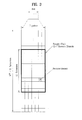
- FIG. 2 illustrates a radio frame structure.
- uplink/downlink data packet transmission is performed on a subframe-by-subframe basis.
- a subframe is defined as a predetermined time interval including a plurality of OFDM symbols.
- 3GPP LTE supports a type-1 radio frame structure applicable to FDD (Frequency Division Duplex) and a type-2 radio frame structure applicable to TDD (Time Division Duplex).
- FIG. 2(a) illustrates a type-1 radio frame structure.
- a downlink subframe includes 10 subframes each of which includes 2 slots in the time domain.
- a time for transmitting a subframe is defined as a transmission time interval (TTI).
- TTI transmission time interval
- each subframe has a length of 1ms and each slot has a length of 0.5ms.
- a slot includes a plurality of OFDM symbols in the time domain and includes a plurality of resource blocks (RBs) in the frequency domain. Since downlink uses OFDM in 3GPP LTE, an OFDM symbol represents a symbol period. The OFDM symbol may be called an SC-FDMA symbol or symbol period.
- An RB as a resource allocation unit may include a plurality of consecutive subcarriers in one slot.
- FIG. 2(b) illustrates a type-2 radio frame structure.
- the type-2 radio frame includes 2 half frames. Each half frame includes 5 subframes, a Downlink Pilot Time Slot (DwPTS), a Guard Period (GP), and an Uplink Pilot Time Slot (UpPTS), and one subframe consists of 2 slots.
- the DwPTS is used for initial cell search, synchronization or channel estimation.
- the UpPTS is used for channel estimation in a BS and UL transmission synchronization acquisition in a UE.
- the GP eliminates UL interference caused by multipath delay of a DL signal between a UL and a DL.
- FIG. 3 illustrates a resource grid of a downlink slot.
- a downlink slot includes a plurality of OFDM symbols in the time domain.
- the number of OFDM symbols included per slot may depend on cyclic prefix (CP) configuration.
- CP cyclic prefix
- the number of OFDM symbols included in one slot may be 7.
- the number of OFDM symbols included per slot may be 6.
- FIG. 3 illustrates a case in which one downlink slot includes 7 OFDM symbols and one resource block (RB) includes 12 subcarriers in the frequency domain.
- Each element on the resource grid is referred to as a resource element (RE).
- One RB may include 12 ⁇ 7 REs.
- the number N RB of RBs included in the downlink slot depends on downlink transmit bandwidth.
- the structure of an uplink slot may be equal to that of the downlink slot.
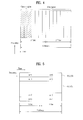
- FIG. 4 illustrates a downlink slot structure
- a maximum of 3 (4) OFDM symbols located in a front portion of a first slot within a subframe correspond to a control region to which a control channel is allocated.
- the remaining OFDM symbols correspond to a data region to which a physical downlink shared chancel (PDSCH) is allocated.
- Examples of downlink control channels used in 3GPP LTE include a physical control format indicator channel (PCFICH), a physical downlink control channel (PDCCH), a physical hybrid ARQ indicator channel (PHICH), etc.
- the PCFICH is transmitted at a first OFDM symbol of a subframe and carries information regarding the number of OFDM symbols used for transmission of control channels within the subframe.
- the PHICH is a response to uplink transmission and carries a HARQ acknowledgment (ACK)/negative-acknowledgment (NACK) signal.
- Control information transmitted through the PDCCH is referred to as downlink control information (DCI).
- DCI includes uplink or downlink scheduling information or an uplink transmit (Tx) power control command for an arbitrary UE group.
- a PDCCH carries a message known as DCI and DCI includes resource allocation information and control information for a UE or UE group.
- the PDCCH carries a transport format and a resource allocation of a downlink shared channel (DL-SCH), resource allocation information of an uplink shared channel (UL-SCH), paging information on a paging channel (PCH), system information on the DL-SCH, information on resource allocation of an upper-layer control message such as a random access response transmitted on the PDSCH, a set of Tx power control commands on individual UEs within an arbitrary UE group, a Tx power control command, information on activation of a voice over IP (VoIP), etc.
- DL-SCH downlink shared channel
- UL-SCH uplink shared channel
- PCH paging information on a paging channel
- system information on the DL-SCH information on resource allocation of an upper-layer control message such as a random access response transmitted on the PDSCH, a set of Tx power control commands on individual
- a BS determines a PDCCH format according to DCI to be transmitted to a UE, and attaches a cyclic redundancy check (CRC) to control information.
- the CRC is masked with a unique identifier (referred to as a radio network temporary identifier (RNTI)) according to an owner or usage of the PDCCH.
- RNTI radio network temporary identifier
- a unique identifier e.g., cell-RNTI (C-RNTI) of the UE may be masked to the CRC.
- a paging identifier e.g., paging-RNTI (P-RNTI)
- P-RNTI paging-RNTI
- SI-RNTI system information RNTI
- RA-RNTI random access-RNTI
- the PDCCH is transmitted on an aggregation of one or several consecutive control channel elements (CCEs).
- the CCE is a logical allocation unit used to provide the PDCCH with a coding rate based on a state of a radio channel.
- the CCE corresponds to a plurality of resource element groups (REGs).
- REGs resource element groups
- One REG corresponds to 4 neighboring REs in one OFDM symbol.
- a PDCCH format and the number of bits of the available PDCCH are determined by a correlation between the number of CCEs and a coding rate provided by CCEs.
- Table 1 shows the relationship among a CCE, a REG and a PDCCH according to PDCCH format.
- PDCCH format Number of CCEs (n) Number of REGs Number of PDCCH bits 0 1 9 72 1 2 18 144 2 4 36 288 3 8 72 576
- CCEs are sequentially numbered.
- transmission of a PDCCH having a format including n CCEs can be started using as many CCEs as a multiple of n.
- the number of CCEs used to transmit a specific PDCCH is determined by a BS according to channel condition. For example, if a PDCCH is for a UE having a high-quality downlink channel (e.g. a channel close to the BS), only one CCE can be used for PDCCH transmission. However, for a UE having a poor channel (e.g. a channel close to a cell edge), 8 CCEs can be used for PDCCH transmission in order to obtain sufficient robustness.
- a power level of the PDCCH can be controlled according to channel condition.
- a UE monitors a plurality of PDCCH candidates within a control region to detect a PDCCH assigned thereto.
- monitoring includes blind decoding (BD).
- resources i.e. a CCE set
- SS search space
- LTE(-A) the search space has a size depending on PDCCH format.
- UE-specific and UE-common search spaces are defined.
- the UE-specific search space is individually set for each UE, whereas the UE-common search space is known to all UEs.
- the UE-specific and UE-common search spaces may overlap for a predetermined UE. Sizes of the UE-specific and UE-common search spaces are shown in Table 2. [Table 2] PDCCH format Number of CCEs (n) Number of candidates in UE-common SS Number of candidates in UE-specific SS 0 1 - 6 1 2 - 6 2 4 4 2 3 8 2 2 2
- the UE is not required to simultaneously search for all defined DCI formats.
- the UE searches for formats 0 and 1A at all times in the UE-specific search space. Formats 0 and 1A have the same size and are discriminated from each other by a flag in a message.
- the UE may need to receive an additional format (e.g. format 1, 1B or 2 according to PDSCH transmission mode set by a BS).
- the UE searches for formats 1A and 1C in the UE-common search space.
- the UE may be set to search for format 3 or 3A. Formats 3 and 3A have the same size as that of formats 0 and 1A and may be discriminated from each other by scrambling CRC with different (common) identifiers rather than a UE-specific identifier.
- FIG. 5 illustrates an uplink subframe structure used in LTE(-A).
- an uplink subframe includes a plurality (e.g. 2) of slots.
- a slot may include different numbers of SC-FDMA symbols according to CP length.
- the uplink subframe is divided into a control region and a data region.
- the data region includes a PUSCH and is used to carry a data signal such as audio data.
- the control region includes a PUCCH and is used to carry uplink control information (UCI).
- the PUCCH includes an RB pair located at both ends of the data region in the frequency domain and is hopped in a slot boundary.
- Each SCH includes a primary SCH (P-SCH) and a secondary SCH (S-SCH).
- P-SCH primary SCH
- S-SCH secondary SCH
- PSS primary synchronization signal
- SSS secondary synchronization signal
- the PBCH includes a downlink bandwidth (DL BW), PHICH configuration and a system frame number (SFN). Accordingly, a UE can acquire information on the DL BW, SFN and PHICH configuration by receiving the PBCH.
- DL BW downlink bandwidth
- SFN system frame number
- the PBCH is subjected to cell-specific scrambling, modulation, layer mapping and precoding and then is mapped to physical resources.
- the PBCH is mapped to REs ( k , l ) indicated by Equation 1.
- Equation 1 shows an example of mapping based on one radio frame.
- the coded PBCH is mapped to 4 subframes for 40ms, as shown in FIG. 6 .
- the timing of 40ms is blind-detected and thus explicit signaling of the timing of 40ms is not performed.
- the PBCH is mapped to 4 OFDM symbols and 72 subcarriers (i.e. 6 RBs) within one subframe.
- P-SCH is positioned in the last OFDM symbols of slot #0 and slot #10 within a radio frame in FDD mode (third OFDM symbols of subframes #1/#6 in the case of TDD).
- the P-SCH is transmitted using 72 subcarriers (10 subcarriers being reserved and 62 subcarriers carrying a PSS) in the corresponding OFDM symbol.
- the P-SCH is used to obtain time domain synchronization such as OFDM symbol synchronization, slot synchronization, etc. and/or frequency domain synchronization.
- S-SCH is positioned in OFDM symbols immediately prior to the last OFDM symbols of slot #0 and slot #10 within a radio frame in FDD mode (slot #1 and slot #11 in the case of TDD).
- the S-SCH and P-SCH are positioned in neighboring OFDM symbols.
- the S-SCH is transmitted using 72 subcarriers (10 subcarriers being reserved and 62 subcarriers carrying an SSS) in the corresponding OFDM symbol.
- the S-SCH is used to obtain frame synchronization, cell group ID and/or CP configuration (i.e. information on use of the normal CP or extended CP) of a cell.
- FIG. 8 illustrates a downlink reference signal (RS) pattern.
- CRS common RSs
- CRS is a cell-specific signal and is transmitted per subframe through the whole band.
- CRSs for a maximum of 4 antenna ports i.e. antenna ports #0 to #3
- DMRS demodulation reference signal
- DMRS is used to demodulate a signal (e.g. PDSCH signal) of each layer during multi-antenna transmission.
- DMRS is a UE-specific signal.
- a maximum of 8 layers and DMRSs for the same may be used although the number of layers is not limited thereto. For convenience, DMRSs for layers #0 to #7 are respectively referred to as DMRSs #0 to #7.
- DMRS is multiplexed to the same resource in an RB according to code division multiplexing (CDM).
- CDM code division multiplexing
- a DMRS for each layer is spread using a spreading code (e.g. a Walsh code, an orthogonal code such as a DFT code, etc.) and then multiplexed to the same RE.
- a spreading code e.g. a Walsh code, an orthogonal code such as a DFT code, etc.
- DMRSs for layers #0 and #1 can be spread using a spreading factor (SF) of 2 in each slot in the time domain and then multiplexed to the same RE.
- the DMRS for layer #0 can be spread using [+1 +1 and the DMRS for layer #1 can be spread using [+1 -1].
- DMRSs for layers #2 and #3 are spread using different orthogonal codes on the same RE.
- DMRSs for layers #4, #5, #6 and #7 are spread on REs occupied by DMRSs #0, #1, #2 and #3 using a code orthogonal to layers #0, #1, #2 and #3.
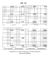
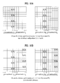
- FIGS. 9a , 9b and 9c illustrate REs (referred to as DMRS REs hereinafter) used for a UE-specific reference signal when the normal CP is used for antenna ports #7, #8, #9 and #10 in a system operating in TDD mode.
- FIG. 9a illustrates DMRS RE configurations in the case of special subframe configurations 1, 2, 6 and 7,
- FIG. 9b illustrates DMRS RE configurations in case of special subframe configurations 3, 4 and 8 and
- FIG. 9c illustrates DMRS RE configurations in case of other downlink subframes.
- FIGS. 10a and 10b illustrate DMRS REs when the extended CP is used for antenna ports #7, #8, #9 and #10 in a system operating in TDD mode.
- FIG. 10a illustrates DMRS RE configurations in case of special subframe configurations 1, 2, 3, 5 and 6 and
- FIG. 10b illustrates DMRS RE configurations in case of other downlink subframes.
- FIG. 11 illustrates a wireless communication system including relays.
- the wireless communication system includes a BS, relays (or relay nodes (RNs)) and UEs.
- a UE communicates with the BS or a relay.
- a UE communicating with the BS is referred to as a macro UE and a UE communicating with a relay is referred to as a relay UE.
- a communication link between the BS and a macro UE is referred to as a macro access link and a communication link between a relay and a relay UE is referred to as a relay access link.
- a communication link between the B and a relay is referred to as a backhaul link.
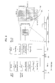
- FIG. 12 illustrates backhaul transmission using an MBSFN subframe.
- a relay transmits a signal to a UE while receiving a signal from a BS or transmits a signal to the BS while receiving a signal from the UE, transmission and reception may not be simultaneously performed since a transmitter and a receiver of the relay interfere with each other. Accordingly, a backhaul link and a relay access link are partitioned according to TDM.
- a backhaul link may be configured in a subframe (referred to as an MBSFN subframe) configured for MBSFN (fake MBSFN method).
- the relay can configure the backhaul link using a data region of the MBSFM subframe.
- the third and following OFDM symbols of the MBSFN subframe can be used for BS-relay transmission (i.e. backhaul transmission).
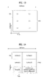
- FIG. 13 illustrates an example of dividing a frequency-time resource (i.e. backhaul resource) for a relay.
- the frequency-time resource shown in FIG. 13 may refer to part of a downlink subframe.
- the frequency-time resource shown in FIG. 13 may correspond to the part of the MBSFN subframe of FIG. 12 other than the control region thereof.
- frequency-time resource regions X-Y may have various sizes.
- X-Y can correspond to resource blocks (RBs).
- An RB refers to a physical resource block (PRB) or a virtual resource block (VRB).
- PRB physical resource block
- VRB virtual resource block
- X-1 corresponds to part of an RB of the first slot
- X-2 corresponds to an RB of the second slot
- [X-1, X-2] corresponds to an RB pair.
- RB may refer to [X-1] or [X-2] or [X-1, X-2] according to context.
- An RBG is composed of one or more consecutive RBs. The number of RBs constituting an RBG may depend upon system bandwidth.
- FIG. 14 illustrates an example of allocating an R-PDCCH/(R-)PDSCH to the frequency-time resource of FIG. 13 .
- Control information e.g. DCI
- the R-PDCCH carries downlink scheduling information (e.g. DL grant) and/or uplink scheduling information (e.g. UL grant).
- a basic resource unit of the R-PDCCH includes a CCE.
- a CCE can be defined as one or more REGs, one or more RBs or one or more RBGs.
- a DL grant of RN#1 when a DL grant of RN#1 is present in resource region 1-1 (refer to FIG. 13 ), (a) data ((R-)PDSCH), (b) UL grant and (c) UL grant for a different RN may be present in resource region 1-2 (refer to FIG. 13 ). It is possible to recognize which one of (a), (b) and (c) is present in resource region 1-2 using resource allocation (RA) information (e.g. RBG or RB allocation information) of the DL grant.
- RA resource allocation
- PDCCH transmission using a data region e.g. PDSCH region
- a data region e.g. PDSCH region
- a specific cell e.g. scheduling cell
- FIG. 15 illustrates an example of allocating a PDCCH to a data region (e.g. PDSCH region) of a subframe.
- a PDCCH legacy PDCCH
- a PDCCH may be additionally allocated using some resources of the data region.
- the PDCCH allocated to the data region is referred to as an enhanced PDCCH (E-PDCCH) (or advanced PDCCH (A-PDCCH).
- E-PDCCH enhanced PDCCH
- A-PDCCH advanced PDCCH
- FIG. 15 illustrates a case in which the E-PDCCH is present in the entire data region (i.e. 2 slots), this is exemplary and the E-PDCCH may be present on a slot basis. That is, an E-PDCCH for a DL grant can be transmitted in the first slot and an E-PDCCH for a UL grant can be transmitted in the second slot, as illustrated in FIG. 14 .
- R-PDCCH carries DCI for a relay.
- DCI has been described with reference to FIG. 4 .
- the R-PDCCH can carry downlink scheduling information and uplink scheduling information for the relay.
- Downlink data (e.g. backhaul data) for the relay is received through a PDSCH.
- a communication procedure using the R-PDCCH/PDSCH is identical/similar to step S107 illustrated in FIG. 1 . That is, the relay receives the R-PDCCH and receives data/control information through the PDSCH indicated by the R-PDCCH.
- An R-PDCCH transmission process (e.g. channel coding, interleaving, multiplexing, etc.) can be performed using processing defined in LTE as long as possible and may be modified as necessary.
- the relay performs PDSCH decoding/demodulation on the basis of the control information obtained from the R-PDCCH. Accordingly, it is very important to correctly acquire R-PDCCH information.
- a PDCCH candidate region (PDCCH search space) is reserved in a control region and a PDCCH of a specific UE is transmitted in a part of the PDCCH candidate region. Accordingly, the UE can obtain the PDCCH thereof from the PDCCH search space through blind decoding.
- the relay can employ a method of transmitting the R-PDCCH through part or all of a previously reserved resource.
- FIG. 16 illustrates a process of allocating a resource for an R-PDCCH and receiving the R-PDCCH.
- a BS transmits R-PDCCH resource allocation (RA) information to a relay (S1210).
- the R-PDCCH RA information may include RB (or VRB) allocation information.
- the RB allocation information may be provided on an RB or RBG basis.
- the R-PDCCH RA information may be transmitted using higher layer (e.g. radio resource control (RRC)) signaling.
- RRC radio resource control
- R-PDCCH RA information is used to reserve a resource (region) for an R-PDCCH.
- the BS transmits the R-PDCCH in a backhaul subframe (S1220).
- the R-PDCCH can be transmitted in part or all of the R-PDCCH resource region (e.g.
- the relay monitors the resource (region) (referred to as an R-PDCCH search space (SS) or simply search space) in which the R-PDCCH can be transmitted (S1230). Specifically, the relay blind-decodes a plurality of R-PDCCH candidates within the search space. Upon detection of the R-PDCCH allocated to the relay, the relay performs operations (e.g. PDSCH reception, PUSCH transmission, Tx power control, etc.) according to the R-PDCCH (not shown) (refer to S107 and S108 of FIG. 1 ).
- operations e.g. PDSCH reception, PUSCH transmission, Tx power control, etc.
- FIG. 17 illustrates an example of configuring a search space (SS) in a data region of a subframe.
- FIG. 17 shows a case in which the R-PDCCH RA information of FIG. 16 includes RBG allocation information.
- RBGs 3, 6 and 9 are set to SSs and a relay performs blind decoding in RBGs 3, 6 and 9 in order to receive an R-PDCCH allocated thereto.
- FIG. 17 illustrates a case in which the SSs use the same resource (e.g. RB, RBG) on a subframe basis, an SS may be independently defined per slot.
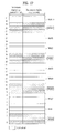
- Table 3 shows special subframe configurations (simply, configurations) and DwPTS/GP/UpPTS durations according thereto.
- Table 3 Special subframe configuration Normal cyclic prefix in downlink Extended cyclic prefix in downlink DwPTS UpPTS DwPTS UpPTS Normal cyclic prefix in uplink Extended cyclic prefix in uplink Normal cyclic prefix in uplink Extended cyclic prefix in uplink 0 6592 ⁇ T s 2192 ⁇ T s 2560 ⁇ T s 7680 ⁇ T s 2192 ⁇ T s 2560 ⁇ T s 1 19760 ⁇ T s 20480 ⁇ T s 2 21952 ⁇ T s 23040 ⁇ T s 3 24144 ⁇ T s 25600 ⁇ T s 4 26336 ⁇ T s 7680 ⁇ T s 4384 ⁇ T s 5120 ⁇ T s 5 6592 ⁇ T s 4384 ⁇ T s 5120 ⁇ T s 20480 ⁇ T s 6 19760 ⁇ T s 23040 ⁇ T s
- FIG. 18 illustrates the numbers of OFDM symbols of DwPTS, GP and UpPTS according to the configurations of Table 3. For convenience, FIG. 18 illustrates a case in which the normal CP is used (i.e. 14 OFDM symbols are used). In addition, it is assumed that a DL grant is transmitted in the first subframe and a UL grant is transmitted in the second subframe.
- the number of OFDM symbols that can be used for backhaul transmission depends upon the configuration. Specifically, configurations 0 and 5 can use the first 3 OFDM symbols of the first slot for DwPTS. Configurations 1, 2, 3, 4, 6, 7 and 8 can use all OFDM symbols of the first slot for DwPTS.
- the number of OFDM symbols of the first slot, which can be used for DwPTS may be limited to 1 in the case of configurations 0 and 5 and to 5 in the case of configurations 1, 2, 3, 4, 6, 7 and 8.
- configurations 1, 2, 3, 4, 6, 7 and 8 can be used for backhaul transmission (e.g. DL grant), it may be difficult to use configurations 0 and 5 for backhaul transmission (e.g. DL grant).
- the numbers of OFDM symbols of the second slot, which are used for DwPTS, are 2, 3 and 4 in the case of configurations 1, 2, 3, 6, 7 and 8, configurations 1, 2, 3, 6, 7 and 8 may be inappropriate for UL grant transmission in the second slot. Accordingly, allocation of a larger number of RBs may be considered for UL grant transmission.
- this method is not desirable because RB resources may not be efficiently used.
- a method for configuring a resource (e.g. SS) for an X-PDCCH (e.g. R-PDCCH and E-PDCCH) will now be described with reference to the attached drawings. While the following description is based on transmission of an X-PDCCH (e.g. R-PDCCH and E-PDCCH) in a system operating in TDD mode, some suggestions of the present invention are also applicable to FDD mode and/or a normal downlink subframe. In this case, related explanations and illustrations are described in corresponding parts. In addition, the following description focuses on operations of a UE/relay/BS in a special subframe and operations of other subframes may be performed based on FIGS. 13 to 17 .
- a resource e.g. SS
- X-PDCCH e.g. R-PDCCH and E-PDCCH
- an additional subframe e.g. backhaul dedicated subframe
- backhaul transmission e.g. R-PDCCH
- E-PDCCH access transmission
- an access subframe may have the structure of FIG. 15 .
- a normal CP case i.e. 7 OFDM symbols per slot
- the present invention can be equally applied to an extended CP case (i.e. 6 OFDM symbols per slot).
- embodiments are independently described in the following, the embodiments may be combined in an arbitrary manner.
- a UL grant as well as a DL grant can be transmitted in the first slot.
- a DL/UL common search space can be configured in the same resource at all times or according to predetermined conditions.
- a DL search space refers to a resource region in which a DL grant R-PDCCH candidate is transmitted and a UL search space refers to a resource region in which a UL grant R-PDCCH candidate is transmitted.
- the DL/UL common search space refers to a resource region in which both the DL grant R-PDCCH candidate and the UL grant R-PDCCH candidate can be transmitted.
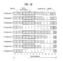
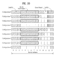
- FIGS. 19 , 20 and 21 illustrate methods for configuring a search space in a special subframe according to the present embodiment.
- the first slot of the special subframe can be used for R-PDCCH transmission and the second slot thereof is not transmitted for R-PDCCH transmission.
- OFDM symbols #M to #6 of the first slot can be used as the DL/UL common search space for the R-PDCCH.
- M is an integer equal to or greater than 1.
- M may have a value depending on the type/characteristics/purpose/configuration (e.g. whether or not an MBSFN subframe is configured, CRS configuration (e.g. 2Tx or 4Tx), etc.) of the special subframe.
- configurations #1, #2, #3, #4, #6, #7 and #8 a resource region for the R-PDCCH is maintained and a conventional DL grant R-PDCCH search process (i.e. monitoring a search space in the first slot only) can be used.
- the first slot to the second OFDM symbol of the second slot of the special subframe can be used for R-PDCCH transmission.
- OFDM symbols #M to #8 can be used as the DL/UL common search space for the R-PDCCH.
- M is an integer equal to or greater than 1.
- M may have a value depending on the purpose/configuration (e.g. whether or not an MBSFN subframe is configured, CRS configuration (e.g. 2Tx or 4Tx), etc.) of the special subframe.
- available DwPTS resources can be used as much as possible while maintaining a resource region for the R-PDCCH in configurations #1, #2, #3, #4, #6, #7 and #8.
- FIG. 21 illustrates a case in which a search space is started from the third OFDM symbol (i.e. symbol #2) of the first slot in consideration of DMRS RE position.
- the DL/UL common search space can be configured according to a predetermined condition. For example, when DMRS REs are disposed in the first slot and the second slot (i.e. configurations #3, #4 and #8), the DL search space and UL search space can be respectively configured in the first slot and the second slot (i.e. the search spaces are separated by the slots).
- DMRS REs are located in the first slot only (i.e.
- a search space including DMRS REs can be configured in the first slot only and used as the DL/UL common search space.
- whether or not the DL/UL common search space is configured is determined depending on the number of DwPTS OFDM symbols (or the configuration) present in the second slot. For example, search spaces are separated by the slots when the number of DwPTS OFDM symbols in the second slot is greater than a specific value (e.g. 4). On the other hand, when the number of DwPTS OFDM symbols in the second slot is less than a specific value (e.g. 4), the DL/UL common search space can be configured throughout the two slots (i.e. subframe).
- An R-PDCCH search space and an E-PDCCH search space may have different DL grant positions, UL grant positions and starting OFDM symbol positions.
- the fourth OFDM symbol (symbol #3) of the first slot corresponds to the starting OFDM symbol in the R-PDCCH search space (refer to FIGS. 19 and 20 )
- the second OFDM symbol (symbol #1) or the third OFDM symbol (symbol #2) of the first slot corresponds to the starting OFDM symbol in the E-PDCCH search space.
- a resource size for RN PDCCH transmission can be limited to a single OFDM symbol.
- the RN PDCCH refers to a PDCCH transmitted by the relay to a UE.
- the ending OFDM symbol of a search space can be previously fixed as illustrated in FIGS. 19 and 20 .
- the ending OFDM symbol of a search space can be set to the ending OFDM symbol of the first slot or to the second OFDM symbol of the second slot.
- the starting and ending OFDM symbols of a search space can be previously appointed between a transmitter and a receiver or semi-statically predetermined through a higher layer signal (e.g. RRC signal).
- the starting and ending OFDM symbols of a search space may be determined depending upon a special subframe configuration. For example, when a special subframe configuration index is given, the starting and ending OFDM symbols of a search space can be recognized. That is, starting and ending OFDM symbol positions can be set for each special subframe configuration according to characteristics of the corresponding configuration. While the above description is based on the R-PDCCH, the above-mentioned methods can be equally applied to determination of the starting and ending OFDM symbols of the E-PDCCH search space.
- subframe #1 and subframe #6 in a radio frame are used as special subframes.
- DwPTS can be limited to 3 OFDM symbols in a corresponding special subframe at all times. Accordingly, when a guard period (GP) is assigned to a single OFDM symbol in the corresponding special subframe, UpPTS is allocated to 10 OFDM symbols.
- This specially limited subframe structure can be applied to a special subframe, in which the synchronization signal is transmitted, only or to all special subframes.
- an R-PDCCH When the third OFDM symbol in which a PSS is present is included in a search space, an R-PDCCH must not be mapped to 6 RBs through which the PSS is transmitted.
- DCI may be rate-matched and then mapped to physical resources in consideration of the 6 RBs through which the PSS is transmitted or mapped to the physical resources and then punctured in consideration of the 6 RBs through which the PSS is transmitted.
- the relay can attempt to decode the R-PDCCH on the assumption that the R-PDCCH has been rate-matched or punctured in the 6 RBs in which the PSS is transmitted.
- puncturing or rate matching may deteriorate performance due to characteristics of control information (i.e. DCI).
- an R-PDCCH SS for a special subframe and an R-PDCCH SS for a normal subframe can be configured such that an R-PDCCH SS configuration for a special subframe and an R-PDCCH SS configuration for a normal subframe are identical to each other at all times, considering that an R-PDCCH SS is configured according to an RRC signal.
- the R-PDCCH SS for a special subframe and the R-PDCCH SS for a normal subframe may be respectively set and signaled and an SS set that meets predetermined conditions may be used (S1210 of FIG. 16 ).
- SS set #1 can be configured in a special subframe in which the PSS is transmitted and SS set #2 can be used in other subframes.
- SS set #1 can be configured such that the 6RBs through which the PSS is transmitted are not included in SS set #1 and SS set #2 can be configured freely.
- SS set #1 can be configured for all special subframes and SS set #2 can be configured for other subframes.
- the concept of this scheme can be extended to a method of individually configuring SS sets according to subframe, characteristics.
- individual SS sets are assumed to be provided according to a higher layer signal (e.g. RRC signal).
- a method of detecting an SS on the basis of UE-specific ID like the method of detecting an SS of a legacy PDCCH defined in LTE, is applicable.
- the present embodiment can be extended to a case in which an SS is allocated to a specific subframe in which a specific control channel signal (e.g. P-SCH, S-SCH, P-BCH or the like) is transmitted.
- a specific control channel signal e.g. P-SCH, S-SCH, P-BCH or the like
- the present embodiment can be applied to both TDD mode and FDD mode operations.
- the X-PDCCH when an X-PDCCH is allocated to the specific subframe, the X-PDCCH (DCI) can be rate-matched or punctured such that such X-PDCCH is not mapped to a frequency resource (e.g.
- a plurality of SS sets may be preconfigured according to a higher layer signal (e.g. RRC signal) (S1210 of FIG. 16 ) and a corresponding SS set may be selectively used according to subframe characteristics/type.
- SS set #1 can be configured in the above-mentioned specific subframe and SS set #2 can be used in other subframes.
- SS set #1 can be configured such that a frequency region through which a specific control channel signal is transmitted is not included in the same and SS set #2 can be configured freely.
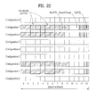
- the relay uses 4 Tx antennas when a special subframe is used as a backhaul subframe, the relay uses at least the first 2 OFDM symbols (i.e. OFDM symbols #0 and #1) of the first slot in order to transmit a CRS to a UE. Accordingly, when a time required for transmission/reception switching is considered, the relay can receive a backhaul signal starting from the fourth OFDM symbol of the special subframe in special subframe. In this case, the relay cannot receive the first DMRS group of the first slot (DMRS REs corresponding to OFDM symbols #2 and #3) (refer to FIG. 22 ) in the case of configurations #1, #2, #6 and #7 (refer to FIG. 9a ).
- the relay cannot receive only the DMRS corresponding to OFDM symbol #2 in practice, the DMRS corresponding to OFDM symbol #3 becomes insignificant because DMRSs are spread in OFDM symbols #2 and #3. Accordingly, the DMRSs corresponding to OFDM symbols #2 and #3 of the first slot cannot be used. That is, the corresponding DMRS REs are punctured, and thus R-PDCCH/PDSCH demodulation performance may be deteriorated.
- CRS based R-PDCCH/PDSCH instead of DMRS based R-PDCCH/PDSCH transmission can be performed to solve a problem such as DMRS RE puncturing.
- CRS based R-PDCCH/PDSCH transmission can be performed in a special subframe at all times.
- the number of symbols occupied by an RN PDCCH of a relay cell may be fixed to 1 in order to receive DMRS REs.
- the relay can receive a backhaul signal starting from OFDM symbol #2 and thus DMRS RE puncturing does not occur.
- the number of antenna ports used by the relay for CRS transmission can be limited to 1 or 2.
- the BS and the relay can use a DMRS corresponding to OFDM symbol #3 for channel estimation without spreading the same.
- This assumption and operations of the BS/relay according thereto can be applied to the corresponding special subframe only.
- the relay when the relay receives a backhaul signal (e.g. R-PDCCH/PDSCH) starting from OFDM symbol #3, the DMRS corresponding to OFDM symbol #2 cannot be received and the DMRS corresponding to OFDM symbol #3 becomes useless, as described above.
- the BS can map the R-PDCCH/PDSCH to the DMRS RE corresponding to OFDM symbol #3 and the relay can perform decoding on the assumption that the R-PDCCH/PDSCH has been mapped to the DMRS RE.
- the BS can puncture the DMRS corresponding to OFDM symbol #3 and map the R-PDCCH/PDSCH to the punctured position.
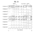
- R-PDCCH/PDSCH decoding can be performed using the second and/or third DMRS groups in the corresponding special subframe.
- the first DMRS group and the second DMRS groups are spaced apart from each other, as shown in FIG. 23 .
- the first DMRS group is not used for channel estimation, R-PDCCH/PDSCH decoding performance and channel estimation performance may be deteriorated. Accordingly, even if the duration of a DwPTS is relatively long (e.g. in special subframe configurations #3, #4 and #8), a DMRS pattern with a short DwPTS duration (e.g. special subframe configurations 1, 2, 6 and 7) can be used.
- DMRS RE overhead or DMRS RE configuration/pattern supposition can be applied differently from the conventional case.
- the relay can consider only DMRS port 7 (i.e. rank 1) since a PDSCH is not present in a PRB pair in which an R-PDCCH is detected.
- a PDSCH is present in a PRB pair in which an R-PDCCH is not detected, which is allocated by a DL grant, and thus the relay can assume DMRS RE overhead (or DMRS RE configuration/pattern) according to a multiple antenna transmission mode.
- This assumption is different from assumption used for the R-PDCCH in a normal DL subframe, and the relay can detect an R-PDCCH in consideration of only rank-1 transmission in a specific special subframe.
- the specific special subframe can be set to a backhaul subframe and/or can refer to a special subframe having a specific configuration (e.g. configuration #0, #1, #2, #5, #6 or #7).
- Embodiments 1 to 5 illustrate cases in which a special subframe is used as a backhaul subframe.
- Operations of embodiments 1 to 5 can be performed in connection with a special subframe configuration index and/or automatically performed only when a specific special subframe is set to a backhaul subframe.
- the transmitter/receiver can perform operations according to embodiments 1 to 5.
- a backhaul subframe can be indicated using a bitmap signal (e.g. N-bitmap signal). The position of each bit in a bitmap indicates the position of a subframe in a radio frame(s) and the value (i.e.
- embodiments 1 to 5 can be automatically performed based on backhaul configuration signaling (e.g. N-bitmap signal) or similar signaling when the corresponding special subframe is set to a backhaul subrframe.
- backhaul configuration signaling e.g. N-bitmap signal
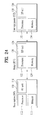
- FIG. 24 illustrates a BS, an RN and a UE to which the present invention is applicable.
- a wireless communication system includes a BS 110, an RN 120 and a UE 130. While the figure shows that UE is connected to the RN for convenience, the UE may be connected to the BS.
- the BS 110 includes a processor 112, a memory 114 and an RF unit 116.
- the processor 112 may be configured to implement the procedures and/or methods proposed by the present invention.
- the memory 114 is connected to the processor 112 and stores various types of information relating to operations of the processor 112.
- the RF unit 116 is connected to the processor 112 and transmits and/or receives RF signals.
- the RN 120 includes a processor 122, a memory 124 and an RF unit 126.
- the processor 122 may be configured to implement the procedures and/or methods proposed by the present invention.
- the memory 124 is connected to the processor 122 and stores various types of information related to operations of the processor 122.
- the RF unit 126 is connected to the processor 122 and transmits and/or receives RF signals.
- the UE 130 includes a processor 132, a memory 134 and an RF unit 136.
- the processor 132 may be configured to implement the procedures and/or methods proposed by the present invention.
- the memory 134 is connected to the processor 132 and stores various types of information related to operations of the processor 132.
- the RF unit 136 is connected to the processor 132 and transmits and/or receives RF signals.
- the BS 110, RN 120 and/or UE 130 may have a single antenna or multiple antennas.
- a description is given, centering on a data transmission and reception relationship between a BS and a UE.
- a specific operation described as performed by the BS may be performed by an upper node of the BS.
- various operations performed for communication with an MS may be performed by the BS, or network nodes other than the BS.
- the term 'eNB' may be replaced with the term 'fixed station', 'Node B', 'Base Station (BS)', 'access point', etc.
- the term 'UE' may be replaced with the term 'Mobile Station (MS)', 'Mobile Subscriber Station (MSS)', 'mobile terminal', etc.
- the embodiments of the present invention may be achieved by various means, for example, hardware, firmware, software, or a combination thereof.
- the methods according to the embodiments of the present invention may be achieved by one or more Application Specific Integrated Circuits (ASICs), Digital Signal Processors (DSPs), Digital Signal Processing Devices (DSPDs), Programmable Logic Devices (PLDs), Field Programmable Gate Arrays (FPGAs), processors, controllers, microcontrollers, microprocessors, etc.
- ASICs Application Specific Integrated Circuits
- DSPs Digital Signal Processors
- DSPDs Digital Signal Processing Devices
- PLDs Programmable Logic Devices
- FPGAs Field Programmable Gate Arrays
- processors controllers, microcontrollers, microprocessors, etc.
- the embodiments of the present invention may be implemented in the form of a module, a procedure, a function, etc.
- software code may be stored in a memory unit and executed by a processor.
- the memory unit may be located at the interior or exterior of the processor and may transmit and receive data to and from the processor via various known means.
- the present invention is used for UE, a BS or other equipment of a wireless communication system. Specifically, the present invention is applicable to a method for transmitting uplink control information and a device therefor.
Landscapes
- Engineering & Computer Science (AREA)
- Signal Processing (AREA)
- Computer Networks & Wireless Communication (AREA)
- Databases & Information Systems (AREA)
- Mobile Radio Communication Systems (AREA)
Abstract
Description
- The present invention relates to a wireless communication system, and more specifically, to a method and device for transmitting control information. The wireless communication system includes a system operating in time division duplex (TDD) mode.
- Wireless communication systems have been widely deployed to provide various types of communication services including voice and data services. In general, a wireless communication system is a multiple access system that supports communication among multiple users by sharing available system resources (e.g. bandwidth, transmit power, etc.) among the multiple users. The multiple access system may adopt a multiple access scheme such as Code Division Multiple Access (CDMA), Frequency Division Multiple Access (FDMA), Time Division Multiple Access (TDMA), Orthogonal Frequency Division Multiple Access (OFDMA), or Single Carrier Frequency Division Multiple Access (SC-FDMA).
- An object of the present invention devised to solve the problem lies in a method and device for efficiently transmitting control information in a wireless communication system. Another object of the present invention is to provide a channel format, a resource allocation method, and a signal processing method and a device therefor to efficiently transmit control information. Another object of the present invention is to provide a method for efficiently allocating resources for transmitting control information and a device therefor.
- The technical problems solved by the present invention are not limited to the above technical problems and those skilled in the art may understand other technical problems from the following description.
- The object of the present invention can be achieved by providing a method for receiving a downlink control channel in a wireless communication system, including: receiving a higher layer signal including a plurality of frequency resource sets; receiving a subframe carrying a plurality of downlink control channel candidates; and monitoring the plurality of downlink control channel candidates within a specific frequency resource set from among the plurality of frequency resources sets for the downlink control channel, wherein the specific frequency resource set is determined according to the type or characteristics of the subframe.
- In another aspect of the present invention, provided herein is a communication device configured to receive a downlink control channel in a wireless communication system, including: a radio frequency (RF) unit; and a processor, wherein the process is configured to receive a higher layer signal including a plurality of frequency resource sets, to receive a subframe carrying a plurality of downlink control channel candidates and to monitor the plurality of downlink control channel candidates within a specific frequency resource set from among the plurality of frequency resources sets for the downlink control channel, wherein the specific frequency resource set is determined according to the type or characteristics of the subframe.
- A first frequency resource set may be used when a predetermined control channel signal is present in the subframe, a second frequency resource set may be used when the predetermined control channel signal is not present in the subframe, and the first frequency resource set may be configured such that a plurality of RBs is not included in the same on the basis of a center frequency.
- The predetermined control channel signal may include at least one of a primary synchronization (P-SCH) signal, a secondary synchronization (S-SCH) signal and a physical broadcast channel (P-BCH) signal.
- The plurality of RBs may include a frequency resource within which the predetermined control channel signal is present.
- A first frequency resource set may be used when the subframe corresponds to a special subframe defined in a time division duplex (TDD) radio frame, a second frequency resource set may be used when the subframe corresponds to a non-special subframe defined in the TDD radio frame, and the first frequency resource set may be configured such that a plurality of RBs is not included in the same on the basis of a center frequency.
- The plurality of control channel candidates may be present in orthogonal frequency division multiplexing (OFDM) symbols #A and #B within the subframe, wherein the OFDM symbol #A corresponds to a second or following OFDM symbol in the first slot of the subframe and the OFDM symbol #B corresponds to an OFDM symbol in the second slot of the subframe.
- According to the present invention, it is possible to efficiently transmit control information in a wireless communication system. In addition, it is possible to provide a channel format, a resource allocation method and a signal processing method for efficiently transmitting control information. Furthermore, it is possible to efficiently allocate resources for transmitting control information and a device therefor.
- The effects of the present invention are not limited to the above-described effects and other effects which are not described herein will become apparent to those skilled in the art from the following description.
- The accompanying drawings, which are included to provide a further understanding of the invention, illustrate embodiments of the invention and together with the description serve to explain the principle of the invention. In the drawings:
-
FIG. 1 illustrates physical channels used in a 3GPP LTE system as an exemplary wires communication system and a signal transmission method using the same; -
FIG. 2 illustrates a radio frame structure; -
FIG. 3 illustrates a resource grid of a downlink slot; -
FIG. 4 illustrates a downlink subframe structure; -
FIG. 5 illustrates an uplink subframe structure; -
FIGS. 6 and7 illustrate a physical broadcast channel (PBCH) and a synchronization channel (SCH); -
FIG. 8 illustrates a downlink reference signal (RS) pattern; -
FIGS. 9 and10 illustrate demodulation reference signal element (DMRS RE) configurations in TDD mode; -
FIG. 11 illustrates a wireless communication system including relays; -
FIG. 12 illustrates backhaul transmission using a multicast broadcast single frequency network (MBSFN) subframe; -
FIG. 13 illustrates an example of dividing a frequency-time resource for a relay; -
FIG. 14 illustrates allocation of a relay (R)-PDCCH/R-PDSCH; -
FIG. 15 illustrates allocation of a PDCCH to a data region (e.g. PDSCH region) of a subframe; -
FIG. 16 illustrates a process of allocating a resource for an R-PDCCH and receiving a PDCCH; -
FIG. 17 illustrates an example of configuring a search space in a data region of a subframe; -
FIG. 18 illustrates a special subframe structure; -
FIGS. 19 ,20 and21 illustrate methods for configuring a search space in a special subframe according to embodiments of the present invention; -
FIGS. 22 and23 illustrate DMRS groups according to special subframe configurations; and -
FIG. 24 illustrates a base station (BS), a relay node (RN) and UE applicable to the present invention. - Embodiments of the present invention are applicable to a variety of wireless access technologies such as Code Division Multiple Access (CDMA), Frequency Division Multiple Access (FDMA), Time Division Multiple Access (TDMA), Orthogonal Frequency Division Multiple Access (OFDMA), and Single Carrier Frequency Division Multiple Access (SC-FDMA). CDMA can be implemented as a radio technology such as Universal Terrestrial Radio Access (UTRA) or CDMA2000. TDMA can be implemented as a radio technology such as Global System for Mobile communications (GSM)/General Packet Radio Service (GPRS)/Enhanced Data Rates for GSM Evolution (EDGE). OFDMA can be implemented as a radio technology such as Institute of Electrical and Electronics Engineers (IEEE) 802.11 (Wireless Fidelity (Wi-Fi)), IEEE 802.16 (Worldwide interoperability for Microwave Access (WiMAX)), IEEE 802.20, and Evolved UTRA (E-UTRA). UTRA is a part of Universal Mobile Telecommunications System (UMTS). 3rd Generation Partnership Project (3GPP) Long Term Evolution (LTE) is a part of Evolved UMTS (E-UMTS) using E-UTRA, employing OFDMA for downlink and SC-FDMA for uplink. LTE-Advanced (LTE-A) is the next generation of 3GPP LTE. While the following description is given, centering on 3GPP LTE/LTE-A for clarity, this is purely exemplary and thus should not be construed as limiting the present invention.
- In a wireless communication system, a UE receives information from a BS through downlink (DL) and transmits information to the BS through uplink (UL). Information transmitted/received between the UE and BS includes data and various types of control information, and various physical channels are present according to type/purpose of information transmitted/received between the UE and BS.
-
FIG. 1 illustrates physical channels used in a 3GPP LTE system and a signal transmission method using the same. - When powered on or when a UE initially enters a cell, the UE performs initial cell search involving synchronization with a BS in step S101. For initial cell search, the UE synchronizes with the BS and acquire information such as a cell Identifier (ID) by receiving a Primary Synchronization Channel (P-SCH) and a Secondary Synchronization Channel (S-SCH) from the BS. Then the UE may receive broadcast information from the cell on a Physical Broadcast Channel (PBCH). In the mean time, the UE may determine a downlink channel status by receiving a Downlink Reference Signal (DL-RS) during initial cell search.
- After initial cell search, the UE may acquire more specific system information by receiving a Physical Downlink Control Channel (PDCCH) and receiving a Physical Downlink Shared Channel (PDSCH) based on information of the PDCCH in step S102.
- The UE may perform a random access procedure to access the BS in steps S103 to S106. For random access, the UE may transmit a preamble to the BS on a Physical Random Access Channel (PRACH) (S103) and receive a response message for preamble on a PDCCH and a PDSCH corresponding to the PDCCH (S104). In the case of contention-based random access, the UE may perform a contention resolution procedure by further transmitting the PRACH (S105) and receiving a PDCCH and a PDSCH corresponding to the PDCCH (S106).
- After the foregoing procedure, the UE may receive a PDCCH/PDSCH (S107) and transmit a Physical Uplink Shared Channel (PUSCH)/Physical Uplink Control Channel (PUCCH) (S108), as a general downlink/uplink signal transmission procedure. Here, control information transmitted from the UE to the BS is called uplink control information (UCI). The UCI may include a hybrid automatic repeat and request (HARQ) acknowledgement(ACK)/negative-ACK (HARQ ACK/NACK) signal, a scheduling request (SR), channel state information (CSI), etc. The CSI includes a channel quality indicator (CQI), a precoding matrix index (PMI), a rank indicator (RI), etc. While the UCI is transmitted through a PUCCH in general, it may be transmitted through a PUSCH when control information and traffic data need to be simultaneously transmitted. The UCI may be aperiodically transmitted through a PUSCH at the request/instruction of a network.
-
FIG. 2 illustrates a radio frame structure. In a cellular OFDM wireless packet communication system, uplink/downlink data packet transmission is performed on a subframe-by-subframe basis. A subframe is defined as a predetermined time interval including a plurality of OFDM symbols. 3GPP LTE supports a type-1 radio frame structure applicable to FDD (Frequency Division Duplex) and a type-2 radio frame structure applicable to TDD (Time Division Duplex). -
FIG. 2(a) illustrates a type-1 radio frame structure. A downlink subframe includes 10 subframes each of which includes 2 slots in the time domain. A time for transmitting a subframe is defined as a transmission time interval (TTI). For example, each subframe has a length of 1ms and each slot has a length of 0.5ms. A slot includes a plurality of OFDM symbols in the time domain and includes a plurality of resource blocks (RBs) in the frequency domain. Since downlink uses OFDM in 3GPP LTE, an OFDM symbol represents a symbol period. The OFDM symbol may be called an SC-FDMA symbol or symbol period. An RB as a resource allocation unit may include a plurality of consecutive subcarriers in one slot. -
FIG. 2(b) illustrates a type-2 radio frame structure. The type-2 radio frame includes 2 half frames. Each half frame includes 5 subframes, a Downlink Pilot Time Slot (DwPTS), a Guard Period (GP), and an Uplink Pilot Time Slot (UpPTS), and one subframe consists of 2 slots. The DwPTS is used for initial cell search, synchronization or channel estimation. The UpPTS is used for channel estimation in a BS and UL transmission synchronization acquisition in a UE. The GP eliminates UL interference caused by multipath delay of a DL signal between a UL and a DL. -
FIG. 3 illustrates a resource grid of a downlink slot. - Referring to
FIG. 3 , a downlink slot includes a plurality of OFDM symbols in the time domain. The number of OFDM symbols included per slot may depend on cyclic prefix (CP) configuration. When an OFDM symbol is configured with the normal CP, for example, the number of OFDM symbols included in one slot may be 7. When an OFDM symbol is configured with the extended CP, the number of OFDM symbols included per slot may be 6. When a channel state is unstable, such as when a UE moves at a high speed, the extended CP can be used to reduce inter-symbol interference.FIG. 3 illustrates a case in which one downlink slot includes 7 OFDM symbols and one resource block (RB) includes 12 subcarriers in the frequency domain. Each element on the resource grid is referred to as a resource element (RE). One RB may include 12×7 REs. The number NRB of RBs included in the downlink slot depends on downlink transmit bandwidth. The structure of an uplink slot may be equal to that of the downlink slot. -
FIG. 4 illustrates a downlink slot structure. - Referring to
FIG. 4 , a maximum of 3 (4) OFDM symbols located in a front portion of a first slot within a subframe correspond to a control region to which a control channel is allocated. The remaining OFDM symbols correspond to a data region to which a physical downlink shared chancel (PDSCH) is allocated. Examples of downlink control channels used in 3GPP LTE include a physical control format indicator channel (PCFICH), a physical downlink control channel (PDCCH), a physical hybrid ARQ indicator channel (PHICH), etc. The PCFICH is transmitted at a first OFDM symbol of a subframe and carries information regarding the number of OFDM symbols used for transmission of control channels within the subframe. The PHICH is a response to uplink transmission and carries a HARQ acknowledgment (ACK)/negative-acknowledgment (NACK) signal. Control information transmitted through the PDCCH is referred to as downlink control information (DCI). DCI includes uplink or downlink scheduling information or an uplink transmit (Tx) power control command for an arbitrary UE group. - A PDCCH carries a message known as DCI and DCI includes resource allocation information and control information for a UE or UE group. Specifically, the PDCCH carries a transport format and a resource allocation of a downlink shared channel (DL-SCH), resource allocation information of an uplink shared channel (UL-SCH), paging information on a paging channel (PCH), system information on the DL-SCH, information on resource allocation of an upper-layer control message such as a random access response transmitted on the PDSCH, a set of Tx power control commands on individual UEs within an arbitrary UE group, a Tx power control command, information on activation of a voice over IP (VoIP), etc. A BS determines a PDCCH format according to DCI to be transmitted to a UE, and attaches a cyclic redundancy check (CRC) to control information. The CRC is masked with a unique identifier (referred to as a radio network temporary identifier (RNTI)) according to an owner or usage of the PDCCH. If the PDCCH is for a specific UE, a unique identifier (e.g., cell-RNTI (C-RNTI)) of the UE may be masked to the CRC. Alternatively, if the PDCCH is for a paging message, a paging identifier (e.g., paging-RNTI (P-RNTI)) may be masked to the CRC. If the PDCCH is for system information (more specifically, a system information block (SIB)), a system information RNTI (SI-RNTI) may be masked to the CRC. When the PDCCH is for a random access response, a random access-RNTI (RA-RNTI) may be masked to the CRC.
- The PDCCH is transmitted on an aggregation of one or several consecutive control channel elements (CCEs). The CCE is a logical allocation unit used to provide the PDCCH with a coding rate based on a state of a radio channel. The CCE corresponds to a plurality of resource element groups (REGs). One REG corresponds to 4 neighboring REs in one OFDM symbol. A PDCCH format and the number of bits of the available PDCCH are determined by a correlation between the number of CCEs and a coding rate provided by CCEs.
- Table 1 shows the relationship among a CCE, a REG and a PDCCH according to PDCCH format.
[Table 1] PDCCH format Number of CCEs (n) Number of REGs Number of PDCCH bits 0 1 9 72 1 2 18 144 2 4 36 288 3 8 72 576 - CCEs are sequentially numbered. To simplify a decoding process, transmission of a PDCCH having a format including n CCEs can be started using as many CCEs as a multiple of n. The number of CCEs used to transmit a specific PDCCH is determined by a BS according to channel condition. For example, if a PDCCH is for a UE having a high-quality downlink channel (e.g. a channel close to the BS), only one CCE can be used for PDCCH transmission. However, for a UE having a poor channel (e.g. a channel close to a cell edge), 8 CCEs can be used for PDCCH transmission in order to obtain sufficient robustness. In addition, a power level of the PDCCH can be controlled according to channel condition.
- A UE monitors a plurality of PDCCH candidates within a control region to detect a PDCCH assigned thereto. Here, monitoring includes blind decoding (BD). In LTE(-A), to reduce decoding load of the UE, resources (i.e. a CCE set) in which the plurality of PDCCH candidates can be positioned are limited for the UE. Limited resources that the UE needs to monitor in order to detect the PDCCH allocated thereto may be referred to as 'search space (SS)'. In LTE(-A), the search space has a size depending on PDCCH format. In addition, UE-specific and UE-common search spaces are defined. The UE-specific search space is individually set for each UE, whereas the UE-common search space is known to all UEs. The UE-specific and UE-common search spaces may overlap for a predetermined UE. Sizes of the UE-specific and UE-common search spaces are shown in Table 2.
[Table 2] PDCCH format Number of CCEs (n) Number of candidates in UE-common SS Number of candidates in UE- specific SS 0 1 - 6 1 2 - 6 2 4 4 2 3 8 2 2 - To control computational load of blind decoding based on the number of blind decoding processes to an appropriate level, the UE is not required to simultaneously search for all defined DCI formats. In general, the UE searches for
formats 0 and 1A at all times in the UE-specific search space.Formats 0 and 1A have the same size and are discriminated from each other by a flag in a message. The UE may need to receive an additional format (e.g. format format 3 or 3A.Formats 3 and 3A have the same size as that offormats 0 and 1A and may be discriminated from each other by scrambling CRC with different (common) identifiers rather than a UE-specific identifier. -
FIG. 5 illustrates an uplink subframe structure used in LTE(-A). - Referring to
FIG. 5 , an uplink subframe includes a plurality (e.g. 2) of slots. A slot may include different numbers of SC-FDMA symbols according to CP length. The uplink subframe is divided into a control region and a data region. The data region includes a PUSCH and is used to carry a data signal such as audio data. The control region includes a PUCCH and is used to carry uplink control information (UCI). The PUCCH includes an RB pair located at both ends of the data region in the frequency domain and is hopped in a slot boundary. - A detailed description will be given of a physical broadcast channel (PBCH) and a synchronization channel (SCH) of LTE(-A) with reference to
FIGS. 6 and7 . Each SCH includes a primary SCH (P-SCH) and a secondary SCH (S-SCH). A primary synchronization signal (PSS) is transmitted on the P-SCH and a secondary synchronization signal (SSS) is transmitted on the S-SCH. - The PBCH includes a downlink bandwidth (DL BW), PHICH configuration and a system frame number (SFN). Accordingly, a UE can acquire information on the DL BW, SFN and PHICH configuration by receiving the PBCH. Referring to
FIG. 6 , the PBCH is subjected to cell-specific scrambling, modulation, layer mapping and precoding and then is mapped to physical resources. The PBCH is mapped to REs (k, l) indicated byEquation 1.
- Here, l denotes the OFDM symbol index of
slot # 1 ofsubframe # 0 and k denotes a subcarrier index. NDL RB represents the number of RBs within the DL BW and NRB sc represents the number of subcarriers included in an RB.Equation 1 shows an example of mapping based on one radio frame. The coded PBCH is mapped to 4 subframes for 40ms, as shown inFIG. 6 . The timing of 40ms is blind-detected and thus explicit signaling of the timing of 40ms is not performed. As can be seen fromEquation 1 andFIG. 6 , the PBCH is mapped to 4 OFDM symbols and 72 subcarriers (i.e. 6 RBs) within one subframe. - Referring to
FIG. 7 , P-SCH is positioned in the last OFDM symbols ofslot # 0 andslot # 10 within a radio frame in FDD mode (third OFDM symbols ofsubframes # 1/#6 in the case of TDD). The P-SCH is transmitted using 72 subcarriers (10 subcarriers being reserved and 62 subcarriers carrying a PSS) in the corresponding OFDM symbol. The P-SCH is used to obtain time domain synchronization such as OFDM symbol synchronization, slot synchronization, etc. and/or frequency domain synchronization. S-SCH is positioned in OFDM symbols immediately prior to the last OFDM symbols ofslot # 0 andslot # 10 within a radio frame in FDD mode (slot # 1 andslot # 11 in the case of TDD). The S-SCH and P-SCH are positioned in neighboring OFDM symbols. The S-SCH is transmitted using 72 subcarriers (10 subcarriers being reserved and 62 subcarriers carrying an SSS) in the corresponding OFDM symbol. The S-SCH is used to obtain frame synchronization, cell group ID and/or CP configuration (i.e. information on use of the normal CP or extended CP) of a cell. -
FIG. 8 illustrates a downlink reference signal (RS) pattern. - Referring to
FIG. 8 , common RSs (CRS) R0 to R3 are used to acquire information regarding channel state and measure handover in LTE(-A). CRS is a cell-specific signal and is transmitted per subframe through the whole band. CRSs for a maximum of 4 antenna ports (i.e.antenna ports # 0 to #3) may be transmitted although the number of antenna ports is not limited to 4. In LTE-A, a demodulation reference signal (DMRS) is used to demodulate a signal (e.g. PDSCH signal) of each layer during multi-antenna transmission. DMRS is a UE-specific signal. A maximum of 8 layers and DMRSs for the same may be used although the number of layers is not limited thereto. For convenience, DMRSs forlayers # 0 to #7 are respectively referred to asDMRSs # 0 to #7. - DMRS is multiplexed to the same resource in an RB according to code division multiplexing (CDM). Specifically, a DMRS for each layer is spread using a spreading code (e.g. a Walsh code, an orthogonal code such as a DFT code, etc.) and then multiplexed to the same RE. For example, DMRSs for
layers # 0 and #1 can be spread using a spreading factor (SF) of 2 in each slot in the time domain and then multiplexed to the same RE. The DMRS forlayer # 0 can be spread using [+1 +1 and the DMRS forlayer # 1 can be spread using [+1 -1]. Similarly, DMRSs forlayers # 2 and #3 are spread using different orthogonal codes on the same RE. DMRSs forlayers # 4, #5, #6 and #7 are spread on REs occupied byDMRSs # 0, #1, #2 and #3 using a code orthogonal tolayers # 0, #1, #2 and #3. A code with SF=2 is used for up to 4 layers and a code with SF=4 is used for DMRS for 5 or more layers. In LTE-A, antenna ports for DMRS correspond to {7, 8, ..., n+6} (n being the number of layers) (e.g. R7 to R10 when n=4). -
FIGS. 9a ,9b and9c illustrate REs (referred to as DMRS REs hereinafter) used for a UE-specific reference signal when the normal CP is used forantenna ports # 7, #8, #9 and #10 in a system operating in TDD mode.FIG. 9a illustrates DMRS RE configurations in the case ofspecial subframe configurations FIG. 9b illustrates DMRS RE configurations in case ofspecial subframe configurations FIG. 9c illustrates DMRS RE configurations in case of other downlink subframes. -
FIGS. 10a and 10b illustrate DMRS REs when the extended CP is used forantenna ports # 7, #8, #9 and #10 in a system operating in TDD mode.FIG. 10a illustrates DMRS RE configurations in case ofspecial subframe configurations FIG. 10b illustrates DMRS RE configurations in case of other downlink subframes. -
FIG. 11 illustrates a wireless communication system including relays. The wireless communication system includes a BS, relays (or relay nodes (RNs)) and UEs. A UE communicates with the BS or a relay. For convenience, a UE communicating with the BS is referred to as a macro UE and a UE communicating with a relay is referred to as a relay UE. A communication link between the BS and a macro UE is referred to as a macro access link and a communication link between a relay and a relay UE is referred to as a relay access link. A communication link between the B and a relay is referred to as a backhaul link. -
FIG. 12 illustrates backhaul transmission using an MBSFN subframe. When a relay transmits a signal to a UE while receiving a signal from a BS or transmits a signal to the BS while receiving a signal from the UE, transmission and reception may not be simultaneously performed since a transmitter and a receiver of the relay interfere with each other. Accordingly, a backhaul link and a relay access link are partitioned according to TDM. In LTE-A, a backhaul link may be configured in a subframe (referred to as an MBSFN subframe) configured for MBSFN (fake MBSFN method). Since the UE receives only a control region of the MBSFN subframe, the relay can configure the backhaul link using a data region of the MBSFM subframe. For example, the third and following OFDM symbols of the MBSFN subframe can be used for BS-relay transmission (i.e. backhaul transmission). -
FIG. 13 illustrates an example of dividing a frequency-time resource (i.e. backhaul resource) for a relay. The frequency-time resource shown inFIG. 13 may refer to part of a downlink subframe. Specifically, the frequency-time resource shown inFIG. 13 may correspond to the part of the MBSFN subframe ofFIG. 12 other than the control region thereof. - In
FIG. 13 , frequency-time resource regions X-Y (X=1, 2 and 3; Y=1 and 2) may have various sizes. For example, X-Y can correspond to resource blocks (RBs). An RB refers to a physical resource block (PRB) or a virtual resource block (VRB). In this case, X-1 corresponds to part of an RB of the first slot, X-2 corresponds to an RB of the second slot and [X-1, X-2] corresponds to an RB pair. In the following description, RB may refer to [X-1] or [X-2] or [X-1, X-2] according to context. An RBG is composed of one or more consecutive RBs. The number of RBs constituting an RBG may depend upon system bandwidth. -
FIG. 14 illustrates an example of allocating an R-PDCCH/(R-)PDSCH to the frequency-time resource ofFIG. 13 . Control information (e.g. DCI) is transmitted on the R-PDCCH and data is transmitted on the (R-)PDSCH. The R-PDCCH carries downlink scheduling information (e.g. DL grant) and/or uplink scheduling information (e.g. UL grant). A basic resource unit of the R-PDCCH includes a CCE. A CCE can be defined as one or more REGs, one or more RBs or one or more RBGs. - Referring to
FIG. 14 , when a DL grant ofRN# 1 is present in resource region 1-1 (refer toFIG. 13 ), (a) data ((R-)PDSCH), (b) UL grant and (c) UL grant for a different RN may be present in resource region 1-2 (refer toFIG. 13 ). It is possible to recognize which one of (a), (b) and (c) is present in resource region 1-2 using resource allocation (RA) information (e.g. RBG or RB allocation information) of the DL grant. - Similarly to a relay system, PDCCH transmission using a data region (e.g. PDSCH region) of a subframe between a BS and a UE or between a relay and a UE is under discussion. This is because the quantity of PDCCHs that need to be transmitted by a specific cell (e.g. scheduling cell) increases due to cross-carrier scheduling, for example.
-
FIG. 15 illustrates an example of allocating a PDCCH to a data region (e.g. PDSCH region) of a subframe. Referring toFIG. 15 , a PDCCH (legacy PDCCH) according to LTE can be allocated to a control region of the subframe. A PDCCH may be additionally allocated using some resources of the data region. For convenience, the PDCCH allocated to the data region is referred to as an enhanced PDCCH (E-PDCCH) (or advanced PDCCH (A-PDCCH). WhileFIG. 15 illustrates a case in which the E-PDCCH is present in the entire data region (i.e. 2 slots), this is exemplary and the E-PDCCH may be present on a slot basis. That is, an E-PDCCH for a DL grant can be transmitted in the first slot and an E-PDCCH for a UL grant can be transmitted in the second slot, as illustrated inFIG. 14 . - A description will be given of a method for allocating and operating a resource for a downlink control channel using a data region (e.g. PDSCH) of a subframe. While the following description is based on a relay system, the method can be equally/similarly applied to a BS-UE system or a relay-UE system, as described above with reference to
FIG. 15 . Accordingly, the BS-relay can be replaced by a BS-UE or a relay-UE in the following description. A relay and a UE may be normalized as a receiver in terms of signal reception and a BS and a relay may be normalized as a transmitter in terms of signal transmission. In the following description, an R-PDCCH can be replaced by an E-PDCCH illustrated inFIG. 15 . R-PDCCH and E-PDCCH differ from legacy PDCCH and may be commonly referred to as X-PDCCH (simply, PDCCH). - R-PDCCH and PDSCH will now be described in more detail. R-PDCCH carries DCI for a relay. DCI has been described with reference to
FIG. 4 . For example, the R-PDCCH can carry downlink scheduling information and uplink scheduling information for the relay. Downlink data (e.g. backhaul data) for the relay is received through a PDSCH. A communication procedure using the R-PDCCH/PDSCH is identical/similar to step S107 illustrated inFIG. 1 . That is, the relay receives the R-PDCCH and receives data/control information through the PDSCH indicated by the R-PDCCH. An R-PDCCH transmission process (e.g. channel coding, interleaving, multiplexing, etc.) can be performed using processing defined in LTE as long as possible and may be modified as necessary. - The relay performs PDSCH decoding/demodulation on the basis of the control information obtained from the R-PDCCH. Accordingly, it is very important to correctly acquire R-PDCCH information. In LTE, a PDCCH candidate region (PDCCH search space) is reserved in a control region and a PDCCH of a specific UE is transmitted in a part of the PDCCH candidate region. Accordingly, the UE can obtain the PDCCH thereof from the PDCCH search space through blind decoding. In a similar manner, the relay can employ a method of transmitting the R-PDCCH through part or all of a previously reserved resource.
-
FIG. 16 illustrates a process of allocating a resource for an R-PDCCH and receiving the R-PDCCH. - Referring to
FIG. 16 , a BS transmits R-PDCCH resource allocation (RA) information to a relay (S1210). The R-PDCCH RA information may include RB (or VRB) allocation information. The RB allocation information may be provided on an RB or RBG basis. The R-PDCCH RA information may be transmitted using higher layer (e.g. radio resource control (RRC)) signaling. Here, R-PDCCH RA information is used to reserve a resource (region) for an R-PDCCH. The BS transmits the R-PDCCH in a backhaul subframe (S1220). The R-PDCCH can be transmitted in part or all of the R-PDCCH resource region (e.g. M RBs) reserved in step S1210. Accordingly, the relay monitors the resource (region) (referred to as an R-PDCCH search space (SS) or simply search space) in which the R-PDCCH can be transmitted (S1230). Specifically, the relay blind-decodes a plurality of R-PDCCH candidates within the search space. Upon detection of the R-PDCCH allocated to the relay, the relay performs operations (e.g. PDSCH reception, PUSCH transmission, Tx power control, etc.) according to the R-PDCCH (not shown) (refer to S107 and S108 ofFIG. 1 ). -
FIG. 17 illustrates an example of configuring a search space (SS) in a data region of a subframe.FIG. 17 shows a case in which the R-PDCCH RA information ofFIG. 16 includes RBG allocation information. Referring toFIG. 17 ,RBGs RBGs FIG. 17 illustrates a case in which the SSs use the same resource (e.g. RB, RBG) on a subframe basis, an SS may be independently defined per slot. - A description will be given of the structure of a special subframe applied to a TDD radio frame and a problem when DCI is transmitted in the special subframe.
- Table 3 shows special subframe configurations (simply, configurations) and DwPTS/GP/UpPTS durations according thereto.
[Table 3] Special subframe configuration Normal cyclic prefix in downlink Extended cyclic prefix in downlink DwPTS UpPTS DwPTS UpPTS Normal cyclic prefix in uplink Extended cyclic prefix in uplink Normal cyclic prefix in uplink Extended cyclic prefix in uplink 0 6592·T s 2192·T s 2560·T s 7680·T s 2192·T s 2560· T s1 19760·T s 20480· T s2 21952·T s 23040· T s3 24144·T s 25600· T s4 26336·T s 7680·T s 4384·T s 5120· T s5 6592·T s 4384·T s 5120·T s 20480· T s6 19760·T s 23040· T s7 21952·T s - - - 8 24144·T s - - - -
FIG. 18 illustrates the numbers of OFDM symbols of DwPTS, GP and UpPTS according to the configurations of Table 3. For convenience,FIG. 18 illustrates a case in which the normal CP is used (i.e. 14 OFDM symbols are used). In addition, it is assumed that a DL grant is transmitted in the first subframe and a UL grant is transmitted in the second subframe. - Referring to
FIG. 18 , the number of OFDM symbols that can be used for backhaul transmission (i.e. DwPTS) depends upon the configuration. Specifically,configurations Configurations configurations configurations configurations configurations configurations configurations - To solve the above-described problem, a method for configuring a resource (e.g. SS) for an X-PDCCH (e.g. R-PDCCH and E-PDCCH) will now be described with reference to the attached drawings. While the following description is based on transmission of an X-PDCCH (e.g. R-PDCCH and E-PDCCH) in a system operating in TDD mode, some suggestions of the present invention are also applicable to FDD mode and/or a normal downlink subframe. In this case, related explanations and illustrations are described in corresponding parts. In addition, the following description focuses on operations of a UE/relay/BS in a special subframe and operations of other subframes may be performed based on
FIGS. 13 to 17 . - Furthermore, while the following description is based on the assumption that an MBSFN subframe is used for backhaul transmission, an additional subframe (e.g. backhaul dedicated subframe) may be defined for backhaul transmission. In addition, while the following description focuses on backhaul transmission (e.g. R-PDCCH), the present invention may be equally/similarly applied to access transmission (e.g. E-PDCCH). In this case, an access subframe may have the structure of
FIG. 15 . Further, the following description assumes a normal CP case (i.e. 7 OFDM symbols per slot), the present invention can be equally applied to an extended CP case (i.e. 6 OFDM symbols per slot). Moreover, while embodiments are independently described in the following, the embodiments may be combined in an arbitrary manner. - According to the present embodiment, a UL grant as well as a DL grant can be transmitted in the first slot. To achieve this, a DL/UL common search space can be configured in the same resource at all times or according to predetermined conditions. Here, a DL search space refers to a resource region in which a DL grant R-PDCCH candidate is transmitted and a UL search space refers to a resource region in which a UL grant R-PDCCH candidate is transmitted. The DL/UL common search space refers to a resource region in which both the DL grant R-PDCCH candidate and the UL grant R-PDCCH candidate can be transmitted.
-
FIGS. 19 ,20 and21 illustrate methods for configuring a search space in a special subframe according to the present embodiment. Referring toFIG. 19 , only the first slot of the special subframe can be used for R-PDCCH transmission and the second slot thereof is not transmitted for R-PDCCH transmission. Specifically, OFDM symbols #M to #6 of the first slot can be used as the DL/UL common search space for the R-PDCCH. Here, M is an integer equal to or greater than 1. M may have a value depending on the type/characteristics/purpose/configuration (e.g. whether or not an MBSFN subframe is configured, CRS configuration (e.g. 2Tx or 4Tx), etc.) of the special subframe. As illustrated,configurations # 0 and #5 cannot be used for R-PDCCH transmission when M=3. According to the present embodiment, inconfigurations # 1, #2, #3, #4, #6, #7 and #8, a resource region for the R-PDCCH is maintained and a conventional DL grant R-PDCCH search process (i.e. monitoring a search space in the first slot only) can be used. - Referring to
FIG. 20 , the first slot to the second OFDM symbol of the second slot of the special subframe can be used for R-PDCCH transmission. Specifically, OFDM symbols #M to #8 can be used as the DL/UL common search space for the R-PDCCH. Here, M is an integer equal to or greater than 1. M may have a value depending on the purpose/configuration (e.g. whether or not an MBSFN subframe is configured, CRS configuration (e.g. 2Tx or 4Tx), etc.) of the special subframe. As illustrated,configurations # 0 and #5 cannot be used for R-PDCCH transmission when M=3. According to the present embodiment, available DwPTS resources can be used as much as possible while maintaining a resource region for the R-PDCCH inconfigurations # 1, #2, #3, #4, #6, #7 and #8. -
FIG. 21 illustrates a case in which a search space is started from the third OFDM symbol (i.e. symbol #2) of the first slot in consideration of DMRS RE position. Referring toFIG. 21 , the DL/UL common search space can be configured according to a predetermined condition. For example, when DMRS REs are disposed in the first slot and the second slot (i.e.configurations # 3, #4 and #8), the DL search space and UL search space can be respectively configured in the first slot and the second slot (i.e. the search spaces are separated by the slots). When DMRS REs are located in the first slot only (i.e.configurations # 1, #2, #6 and #7), a search space including DMRS REs can be configured in the first slot only and used as the DL/UL common search space. Referring toFIG. 21 , whether or not the DL/UL common search space is configured is determined depending on the number of DwPTS OFDM symbols (or the configuration) present in the second slot. For example, search spaces are separated by the slots when the number of DwPTS OFDM symbols in the second slot is greater than a specific value (e.g. 4). On the other hand, when the number of DwPTS OFDM symbols in the second slot is less than a specific value (e.g. 4), the DL/UL common search space can be configured throughout the two slots (i.e. subframe). - An R-PDCCH search space and an E-PDCCH search space may have different DL grant positions, UL grant positions and starting OFDM symbol positions. For example, the fourth OFDM symbol (symbol #3) of the first slot corresponds to the starting OFDM symbol in the R-PDCCH search space (refer to
FIGS. 19 and20 ), whereas the second OFDM symbol (symbol #1) or the third OFDM symbol (symbol #2) of the first slot corresponds to the starting OFDM symbol in the E-PDCCH search space. For configuration of the R-PDCCH search space and E-PDCCH search space, a resource size for RN PDCCH transmission can be limited to a single OFDM symbol. This can be achieved by limiting the number of Tx antennas of the relay to 2. That is, the number of OFDM symbols used for RN PDCCH transmission can be controlled by limiting the number of antennas used for signal transmission. Here, the RN PDCCH refers to a PDCCH transmitted by the relay to a UE. The ending OFDM symbol of a search space can be previously fixed as illustrated inFIGS. 19 and20 . For example, the ending OFDM symbol of a search space can be set to the ending OFDM symbol of the first slot or to the second OFDM symbol of the second slot. For this, the starting and ending OFDM symbols of a search space can be previously appointed between a transmitter and a receiver or semi-statically predetermined through a higher layer signal (e.g. RRC signal). Alternatively, the starting and ending OFDM symbols of a search space may be determined depending upon a special subframe configuration. For example, when a special subframe configuration index is given, the starting and ending OFDM symbols of a search space can be recognized. That is, starting and ending OFDM symbol positions can be set for each special subframe configuration according to characteristics of the corresponding configuration. While the above description is based on the R-PDCCH, the above-mentioned methods can be equally applied to determination of the starting and ending OFDM symbols of the E-PDCCH search space. - In the case of a DL-to-DL switch-point period of 5ms (TDD UL-
DL configurations # 0, #1, #2 and #6),subframe # 1 andsubframe # 6 in a radio frame are used as special subframes. However, since a synchronization signal is transmitted insubframe # 1, a search space needs to be configured in consideration of the synchronization signal. To achieve this, DwPTS can be limited to 3 OFDM symbols in a corresponding special subframe at all times. Accordingly, when a guard period (GP) is assigned to a single OFDM symbol in the corresponding special subframe, UpPTS is allocated to 10 OFDM symbols. This specially limited subframe structure can be applied to a special subframe, in which the synchronization signal is transmitted, only or to all special subframes. - When the third OFDM symbol in which a PSS is present is included in a search space, an R-PDCCH must not be mapped to 6 RBs through which the PSS is transmitted. To achieve this, DCI may be rate-matched and then mapped to physical resources in consideration of the 6 RBs through which the PSS is transmitted or mapped to the physical resources and then punctured in consideration of the 6 RBs through which the PSS is transmitted. In this case, the relay can attempt to decode the R-PDCCH on the assumption that the R-PDCCH has been rate-matched or punctured in the 6 RBs in which the PSS is transmitted. However, puncturing or rate matching may deteriorate performance due to characteristics of control information (i.e. DCI). Accordingly, a method of configuring an SS set such that resources (e.g. an SS) for R-PDCCH transmission do not include a PSS can be considered as an alternative. In this case, an R-PDCCH SS for a special subframe and an R-PDCCH SS for a normal subframe can be configured such that an R-PDCCH SS configuration for a special subframe and an R-PDCCH SS configuration for a normal subframe are identical to each other at all times, considering that an R-PDCCH SS is configured according to an RRC signal. Alternatively, the R-PDCCH SS for a special subframe and the R-PDCCH SS for a normal subframe may be respectively set and signaled and an SS set that meets predetermined conditions may be used (S1210 of
FIG. 16 ). For example, SS set #1 can be configured in a special subframe in which the PSS is transmitted and SS set #2 can be used in other subframes. Here, SS set #1 can be configured such that the 6RBs through which the PSS is transmitted are not included in SS set #1 and SS set #2 can be configured freely. Alternatively, SS set #1 can be configured for all special subframes and SS set #2 can be configured for other subframes. The concept of this scheme can be extended to a method of individually configuring SS sets according to subframe, characteristics. Here, individual SS sets are assumed to be provided according to a higher layer signal (e.g. RRC signal). Furthermore, a method of detecting an SS on the basis of UE-specific ID, like the method of detecting an SS of a legacy PDCCH defined in LTE, is applicable. - While the above description corresponds to a case in which an R-PDCCH SS is allocated to a special subframe, the present embodiment can be extended to a case in which an SS is allocated to a specific subframe in which a specific control channel signal (e.g. P-SCH, S-SCH, P-BCH or the like) is transmitted. In this case, the present embodiment can be applied to both TDD mode and FDD mode operations. Specifically, when an X-PDCCH is allocated to the specific subframe, the X-PDCCH (DCI) can be rate-matched or punctured such that such X-PDCCH is not mapped to a frequency resource (e.g. PRBs) through which a specific control channel signal is transmitted or a time-frequency resource (e.g. PRBs * Q OFDM symbols). Otherwise, a plurality of SS sets may be preconfigured according to a higher layer signal (e.g. RRC signal) (S1210 of
FIG. 16 ) and a corresponding SS set may be selectively used according to subframe characteristics/type. For example, SS set #1 can be configured in the above-mentioned specific subframe and SS set #2 can be used in other subframes. Here, SS set #1 can be configured such that a frequency region through which a specific control channel signal is transmitted is not included in the same and SS set #2 can be configured freely. - If the relay uses 4 Tx antennas when a special subframe is used as a backhaul subframe, the relay uses at least the first 2 OFDM symbols (i.e.
OFDM symbols # 0 and #1) of the first slot in order to transmit a CRS to a UE. Accordingly, when a time required for transmission/reception switching is considered, the relay can receive a backhaul signal starting from the fourth OFDM symbol of the special subframe in special subframe. In this case, the relay cannot receive the first DMRS group of the first slot (DMRS REs corresponding toOFDM symbols # 2 and #3) (refer toFIG. 22 ) in the case ofconfigurations # 1, #2, #6 and #7 (refer toFIG. 9a ). While the relay cannot receive only the DMRS corresponding toOFDM symbol # 2 in practice, the DMRS corresponding toOFDM symbol # 3 becomes insignificant because DMRSs are spread inOFDM symbols # 2 and #3. Accordingly, the DMRSs corresponding toOFDM symbols # 2 and #3 of the first slot cannot be used. That is, the corresponding DMRS REs are punctured, and thus R-PDCCH/PDSCH demodulation performance may be deteriorated. - To solve the above-mentioned problem, a method of using the CRS instead of the DMRS can be considered. That is, CRS based R-PDCCH/PDSCH instead of DMRS based R-PDCCH/PDSCH transmission can be performed to solve a problem such as DMRS RE puncturing. To implement this, CRS based R-PDCCH/PDSCH transmission can be performed in a special subframe at all times.
- Alternatively, the number of symbols occupied by an RN PDCCH of a relay cell may be fixed to 1 in order to receive DMRS REs. In this case, the relay can receive a backhaul signal starting from
OFDM symbol # 2 and thus DMRS RE puncturing does not occur. To achieve this, the number of antenna ports used by the relay for CRS transmission can be limited to 1 or 2. - Alternatively, on the assumption that an R-PDCCH carries a DMRS for a single antenna port at all times, the BS and the relay can use a DMRS corresponding to
OFDM symbol # 3 for channel estimation without spreading the same. This assumption and operations of the BS/relay according thereto can be applied to the corresponding special subframe only. - Alternatively, when the relay receives a backhaul signal (e.g. R-PDCCH/PDSCH) starting from
OFDM symbol # 3, the DMRS corresponding toOFDM symbol # 2 cannot be received and the DMRS corresponding toOFDM symbol # 3 becomes useless, as described above. In this case, the BS can map the R-PDCCH/PDSCH to the DMRS RE corresponding toOFDM symbol # 3 and the relay can perform decoding on the assumption that the R-PDCCH/PDSCH has been mapped to the DMRS RE. To implement this, the BS can puncture the DMRS corresponding toOFDM symbol # 3 and map the R-PDCCH/PDSCH to the punctured position. According to this method, R-PDCCH/PDSCH decoding can be performed using the second and/or third DMRS groups in the corresponding special subframe. - In the case of special
subframe configurations # 3, #4 and #8 (refer toFIG. 9b ), the first DMRS group and the second DMRS groups are spaced apart from each other, as shown inFIG. 23 . In this case, if the first DMRS group is not used for channel estimation, R-PDCCH/PDSCH decoding performance and channel estimation performance may be deteriorated. Accordingly, even if the duration of a DwPTS is relatively long (e.g. in specialsubframe configurations # 3, #4 and #8), a DMRS pattern with a short DwPTS duration (e.g.special subframe configurations - It is not desirable to transmit a PDSCH in the second slot since a small number of available OFDM symbols is present in the second slot in configurations other than
configurations # 3, #4 and #8. Configurations may be previously set such that the PDSCH is not transmitted in configurations unsuitable for PDSCH transmission. In this case, DMRS RE overhead (or DMRS RE configuration/pattern) supposition can be applied differently from the conventional case. For example, the relay can consider only DMRS port 7 (i.e. rank 1) since a PDSCH is not present in a PRB pair in which an R-PDCCH is detected. A PDSCH is present in a PRB pair in which an R-PDCCH is not detected, which is allocated by a DL grant, and thus the relay can assume DMRS RE overhead (or DMRS RE configuration/pattern) according to a multiple antenna transmission mode. This assumption is different from assumption used for the R-PDCCH in a normal DL subframe, and the relay can detect an R-PDCCH in consideration of only rank-1 transmission in a specific special subframe. Here, the specific special subframe can be set to a backhaul subframe and/or can refer to a special subframe having a specific configuration (e.g. configuration # 0, #1, #2, #5, #6 or #7). -
Embodiments 1 to 5 illustrate cases in which a special subframe is used as a backhaul subframe. Operations ofembodiments 1 to 5 can be performed in connection with a special subframe configuration index and/or automatically performed only when a specific special subframe is set to a backhaul subframe. For example, when a specific subframe index corresponds to a special subframe and the special subframe is set to a backhaul subframe, the transmitter/receiver can perform operations according toembodiments 1 to 5. A backhaul subframe can be indicated using a bitmap signal (e.g. N-bitmap signal). The position of each bit in a bitmap indicates the position of a subframe in a radio frame(s) and the value (i.e. 0 or 1) of the corresponding bit can indicate whether the subframe is a backhaul subframe (e.g. an MBSFN subframe) or a normal subframe. Alternatively, the operations ofembodiments 1 to 5 can be automatically performed based on backhaul configuration signaling (e.g. N-bitmap signal) or similar signaling when the corresponding special subframe is set to a backhaul subrframe. -
FIG. 24 illustrates a BS, an RN and a UE to which the present invention is applicable. - Referring to
FIG. 24 , a wireless communication system includes aBS 110, anRN 120 and aUE 130. While the figure shows that UE is connected to the RN for convenience, the UE may be connected to the BS. - The
BS 110 includes aprocessor 112, a memory 114 and anRF unit 116. Theprocessor 112 may be configured to implement the procedures and/or methods proposed by the present invention. The memory 114 is connected to theprocessor 112 and stores various types of information relating to operations of theprocessor 112. TheRF unit 116 is connected to theprocessor 112 and transmits and/or receives RF signals. TheRN 120 includes aprocessor 122, amemory 124 and anRF unit 126. Theprocessor 122 may be configured to implement the procedures and/or methods proposed by the present invention. Thememory 124 is connected to theprocessor 122 and stores various types of information related to operations of theprocessor 122. TheRF unit 126 is connected to theprocessor 122 and transmits and/or receives RF signals. TheUE 130 includes aprocessor 132, amemory 134 and anRF unit 136. Theprocessor 132 may be configured to implement the procedures and/or methods proposed by the present invention. Thememory 134 is connected to theprocessor 132 and stores various types of information related to operations of theprocessor 132. TheRF unit 136 is connected to theprocessor 132 and transmits and/or receives RF signals. TheBS 110,RN 120 and/orUE 130 may have a single antenna or multiple antennas. - The embodiments of the present invention described hereinbelow are combinations of elements and features of the present invention. The elements or features may be considered selective unless otherwise mentioned. Each element or feature may be practiced without being combined with other elements or features. Further, an embodiment of the present invention may be constructed by combining parts of the elements and/or features. Operation orders described in embodiments of the present invention may be rearranged. Some constructions of any one embodiment may be included in another embodiment and may be replaced with corresponding constructions of another embodiment. It is obvious to those skilled in the art that claims that are not explicitly cited in each other in the appended claims may be presented in combination as an embodiment of the present invention or included as a new claim by subsequent amendment after the application is filed.
- In the embodiments of the present invention, a description is given, centering on a data transmission and reception relationship between a BS and a UE. In some cases, a specific operation described as performed by the BS may be performed by an upper node of the BS. Namely, it is apparent that, in a network comprised of a plurality of network nodes including a BS, various operations performed for communication with an MS may be performed by the BS, or network nodes other than the BS. The term 'eNB' may be replaced with the term 'fixed station', 'Node B', 'Base Station (BS)', 'access point', etc. The term 'UE' may be replaced with the term 'Mobile Station (MS)', 'Mobile Subscriber Station (MSS)', 'mobile terminal', etc.
- The embodiments of the present invention may be achieved by various means, for example, hardware, firmware, software, or a combination thereof. In a hardware configuration, the methods according to the embodiments of the present invention may be achieved by one or more Application Specific Integrated Circuits (ASICs), Digital Signal Processors (DSPs), Digital Signal Processing Devices (DSPDs), Programmable Logic Devices (PLDs), Field Programmable Gate Arrays (FPGAs), processors, controllers, microcontrollers, microprocessors, etc.
- In a firmware or software configuration, the embodiments of the present invention may be implemented in the form of a module, a procedure, a function, etc. For example, software code may be stored in a memory unit and executed by a processor. The memory unit may be located at the interior or exterior of the processor and may transmit and receive data to and from the processor via various known means.
- Those skilled in the art will appreciate that the present invention may be carried out in other specific ways than those set forth herein without departing from the spirit and essential characteristics of the present invention. The above embodiments are therefore to be construed in all aspects as illustrative and not restrictive. The scope of the invention should be determined by the appended claims and their legal equivalents, not by the above description, and all changes coming within the meaning and equivalency range of the appended claims are intended to be embraced therein.
- The present invention is used for UE, a BS or other equipment of a wireless communication system. Specifically, the present invention is applicable to a method for transmitting uplink control information and a device therefor.
Claims (12)
- A method for receiving a downlink control channel in a wireless communication system, comprising:receiving a higher layer signal including a plurality of frequency resource sets;receiving a subframe carrying a plurality of downlink control channel candidates; andmonitoring the plurality of downlink control channel candidates within a specific frequency resource set from among the plurality of frequency resources sets for the downlink control channel,wherein the specific frequency resource set is determined according to the type or characteristics of the subframe.
- The method according to claim 1, wherein a first frequency resource set is used when a predetermined control channel signal is present in the subframe, a second frequency resource set is used when the predetermined control channel signal is not present in the subframe, and the first frequency resource set is configured such that a plurality of resource blocks (RBs) is not included in the same on the basis of a center frequency.
- The method according to claim 2, wherein the predetermined control channel signal includes at least one of a primary synchronization (P-SCH) signal, a secondary synchronization (S-SCH) signal and a physical broadcast channel (P-BCH) signal.
- The method according to claim 2, wherein the plurality of RBs includes a frequency resource within which the predetermined control channel signal is present.
- The method according to claim 1, wherein a first frequency resource set is used when the subframe corresponds to a special subframe defined in a time division duplex (TDD) radio frame, a second frequency resource set is used when the subframe corresponds to a non-special subframe defined in the TDD radio frame, and the first frequency resource set is configured such that a plurality of RBs is not included in the same on the basis of a center frequency.
- The method according to claim 1, wherein the plurality of control channel candidates is present in orthogonal frequency division multiplexing (OFDM) symbols #A and #B within the subframe,
wherein the OFDM symbol #A corresponds to a second or following OFDM symbol in the first slot of the subframe and the OFDM symbol #B corresponds to an OFDM symbol in the second slot of the subframe. - A communication device configured to receive a downlink control channel in a wireless communication system, comprising:a radio frequency (RF) unit; anda processor,wherein the process is configured to receive a higher layer signal including a plurality of frequency resource sets, to receive a subframe carrying a plurality of downlink control channel candidates and to monitor the plurality of downlink control channel candidates within a specific frequency resource set from among the plurality of frequency resources sets for the downlink control channel,wherein the specific frequency resource set is determined according to the type or characteristics of the subframe.
- The communication device according to claim 7, wherein a first frequency resource set is used when a predetermined control channel signal is present in the subframe, a second frequency resource set is used when the predetermined control channel signal is not present in the subframe, and the first frequency resource set is configured such that a plurality of RBs is not included in the same on the basis of a center frequency.
- The communication device according to claim 8, wherein the predetermined control channel signal includes at least one of a P-SCH signal, a S-SCH signal and a P-BCH signal.
- The communication device according to claim 8, wherein the plurality of RBs includes a frequency resource within which the predetermined control channel signal is present.
- The communication device according to claim 7, wherein a first frequency resource set is used when the subframe corresponds to a special subframe defined in a TDD radio frame, a second frequency resource set is used when the subframe corresponds to a non-special subframe defined in the TDD radio frame, and the first frequency resource set is configured such that a plurality of RBs is not included in the same on the basis of a center frequency.
- The communication device according to claim 7, wherein the plurality of control channel candidates is present in OFDM symbols #A and #B within the subframe,
wherein the OFDM symbol #A corresponds to a second or following OFDM symbol in the first slot of the subframe and the OFDM symbol #B corresponds to an OFDM symbol in the second slot of the subframe.
Applications Claiming Priority (2)
| Application Number | Priority Date | Filing Date | Title |
|---|---|---|---|
| US201161482180P | 2011-05-03 | 2011-05-03 | |
| PCT/KR2012/003498 WO2012150836A2 (en) | 2011-05-03 | 2012-05-03 | Method for transmitting control information in wireless communication system and device therefor |
Publications (3)
| Publication Number | Publication Date |
|---|---|
| EP2706687A2 true EP2706687A2 (en) | 2014-03-12 |
| EP2706687A4 EP2706687A4 (en) | 2015-01-21 |
| EP2706687B1 EP2706687B1 (en) | 2018-12-19 |
Family
ID=47108153
Family Applications (1)
| Application Number | Title | Priority Date | Filing Date |
|---|---|---|---|
| EP12779316.4A Not-in-force EP2706687B1 (en) | 2011-05-03 | 2012-05-03 | Method and apparatus for receiving control information in wireless communication system |
Country Status (5)
| Country | Link |
|---|---|
| US (1) | US9801169B2 (en) |
| EP (1) | EP2706687B1 (en) |
| KR (1) | KR101467806B1 (en) |
| CN (1) | CN103503349B (en) |
| WO (1) | WO2012150836A2 (en) |
Cited By (2)
| Publication number | Priority date | Publication date | Assignee | Title |
|---|---|---|---|---|
| EP2999140A4 (en) * | 2013-05-16 | 2016-12-14 | Lg Electronics Inc | Method for transmitting signal for improving coverage and apparatus for same |
| EP2978151A4 (en) * | 2013-03-21 | 2016-12-21 | Lg Electronics Inc | Broadcast channel method, method for transceiving broadcast channel signal, and device supporting the same |
Families Citing this family (32)
| Publication number | Priority date | Publication date | Assignee | Title |
|---|---|---|---|---|
| US8792924B2 (en) * | 2011-05-06 | 2014-07-29 | Futurewei Technologies, Inc. | System and method for multi-cell access |
| US9432170B2 (en) * | 2011-05-12 | 2016-08-30 | Lg Electronics Inc. | Method for transmitting signal using plurality of antenna ports and transmission end apparatus for same |
| WO2013001733A1 (en) * | 2011-06-27 | 2013-01-03 | パナソニック株式会社 | Transmitter device, receiver device, transmission method, and reception method |
| KR20140084103A (en) * | 2011-10-10 | 2014-07-04 | 엘지전자 주식회사 | Method and apparatus for transceiving control information in a wireless communication system |
| WO2013062359A1 (en) * | 2011-10-26 | 2013-05-02 | Lg Electronics Inc. | Method for determining transmission power information of downlink subframe and apparatus therefor |
| US9609675B2 (en) * | 2012-01-16 | 2017-03-28 | Lg Electronics Inc. | Method and apparatus for monitoring control channel |
| US20130242766A1 (en) * | 2012-03-14 | 2013-09-19 | Qualcomm Incorporated | Pre-sib2 channel estimation and signal processing in the presence of mbsfn for lte |
| KR101724220B1 (en) * | 2012-11-14 | 2017-04-06 | 엘지전자 주식회사 | Method for operating terminal in carrier aggregation system, and apparatus using said method |
| MX360909B (en) * | 2014-11-15 | 2018-11-22 | Panasonic Ip Corp America | Resource scheduling method, resource determining method, enodeb and user equipment. |
| CN111970103B (en) * | 2014-12-30 | 2023-07-11 | 北京三星通信技术研究有限公司 | Method and equipment for receiving downlink channel and/or downlink reference signal |
| US10264560B2 (en) * | 2014-12-31 | 2019-04-16 | Lg Electronics Inc. | Uplink signal transmitting method and user equipment, and uplink signal receiving method and base station |
| WO2016131475A1 (en) * | 2015-02-17 | 2016-08-25 | Nokia Solutions And Networks Oy | Communication efficiency |
| KR102520403B1 (en) | 2015-06-12 | 2023-04-11 | 삼성전자 주식회사 | Method and apparatus for reporting channel state information in a wireless communication system |
| WO2016204549A1 (en) | 2015-06-19 | 2016-12-22 | 삼성전자 주식회사 | Method and apparatus for transmitting reference signal in wireless communication system |
| US10756799B2 (en) * | 2015-10-23 | 2020-08-25 | Samsung Electronics Co., Ltd | Method and device for transmitting and receiving channel state information in mobile communication system |
| CN107046713B (en) * | 2016-02-05 | 2022-12-02 | 中兴通讯股份有限公司 | Method and device for determining downlink control channel, terminal and base station |
| WO2018021370A1 (en) * | 2016-07-29 | 2018-02-01 | 株式会社Nttドコモ | User terminal and wireless communication method |
| WO2018031644A1 (en) * | 2016-08-10 | 2018-02-15 | Intel IP Corporation | Synchronization signals for multiple numerologies |
| CN115515248A (en) | 2016-08-11 | 2022-12-23 | 弗劳恩霍夫应用研究促进协会 | Sounding feedback with shortened frame structure |
| US20190268096A1 (en) * | 2016-09-16 | 2019-08-29 | Ntt Docomo, Inc. | User terminal and radio communication method |
| US20180132244A1 (en) * | 2016-11-10 | 2018-05-10 | Qualcomm Incorporated | Techniques and apparatuses for configuring a common uplink portion in new radio |
| JP7018059B2 (en) * | 2016-12-07 | 2022-02-09 | エルジー エレクトロニクス インコーポレイティド | Methods and devices for configuring control channels for NR in wireless communication systems |
| CN108271259B (en) * | 2016-12-30 | 2023-10-24 | 华为技术有限公司 | Resource indication method of control channel, user equipment and network equipment |
| US11240799B2 (en) * | 2017-01-05 | 2022-02-01 | Nec Corporation | Method and device for indicating resource allocation |
| US10405305B2 (en) * | 2017-03-24 | 2019-09-03 | Qualcomm Incorporated | Single slot short PUCCH with support for intra slot frequency hopping |
| US11039433B2 (en) * | 2017-05-05 | 2021-06-15 | Qualcomm Incorporated | Channel formats with flexible duration in wireless communications |
| WO2018237032A1 (en) * | 2017-06-21 | 2018-12-27 | Intel Corporation | Collision handling of synchronization signal (ss) blocks |
| WO2019033392A1 (en) * | 2017-08-18 | 2019-02-21 | Oppo广东移动通信有限公司 | Signal transmission method, terminal device and network device |
| WO2020091574A1 (en) * | 2018-11-02 | 2020-05-07 | 엘지전자 주식회사 | Method and device for transmitting or receiving wireless signal in wireless communication system |
| CN111586881B (en) | 2019-02-15 | 2022-09-16 | 华为技术有限公司 | Random access method and device |
| US10887839B2 (en) * | 2019-03-29 | 2021-01-05 | Qualcomm Incorporated | Search space set for wakeup signal |
| CN114747267A (en) * | 2019-10-02 | 2022-07-12 | 株式会社Ntt都科摩 | Terminal and wireless communication method |
Family Cites Families (24)
| Publication number | Priority date | Publication date | Assignee | Title |
|---|---|---|---|---|
| US8009617B2 (en) * | 2007-08-15 | 2011-08-30 | Qualcomm Incorporated | Beamforming of control information in a wireless communication system |
| CN101388760A (en) | 2007-09-12 | 2009-03-18 | 北京三星通信技术研究有限公司 | Device and method of first scheduling unit for transmitting broadcast information |
| CN101222272B (en) * | 2008-01-28 | 2012-10-10 | 中兴通讯股份有限公司 | Signal transmission method of physical descending control channel in descending pilot frequency time slot |
| US9288021B2 (en) * | 2008-05-02 | 2016-03-15 | Qualcomm Incorporated | Method and apparatus for uplink ACK/NACK resource allocation |
| US8873522B2 (en) | 2008-08-11 | 2014-10-28 | Qualcomm Incorporated | Processing measurement gaps in a wireless communication system |
| US9294219B2 (en) | 2008-09-30 | 2016-03-22 | Qualcomm Incorporated | Techniques for supporting relay operation in wireless communication systems |
| KR101557676B1 (en) | 2008-10-31 | 2015-10-06 | 삼성전자주식회사 | Device and method for controlling downlink control information in wireless communication system |
| CN101754230B (en) | 2008-12-17 | 2012-09-05 | 华为技术有限公司 | Carrier polymerizing method in FDD system and device thereof |
| US8537724B2 (en) * | 2009-03-17 | 2013-09-17 | Motorola Mobility Llc | Relay operation in a wireless communication system |
| US9839001B2 (en) | 2009-03-23 | 2017-12-05 | Apple Inc. | Methods and apparatus for optimizing paging mechanisms and publication of dynamic paging mechanisms |
| CN101868033B (en) * | 2009-04-20 | 2013-04-24 | 电信科学技术研究院 | Method and device for controlling downlink subframe and transmitting data of trunk link |
| US8855062B2 (en) | 2009-05-28 | 2014-10-07 | Qualcomm Incorporated | Dynamic selection of subframe formats in a wireless network |
| US8340676B2 (en) * | 2009-06-25 | 2012-12-25 | Motorola Mobility Llc | Control and data signaling in heterogeneous wireless communication networks |
| CN101998509B (en) | 2009-08-28 | 2013-01-23 | 华为技术有限公司 | Method and device for determining searching space and candidate control channel resources |
| KR101783064B1 (en) * | 2009-09-28 | 2017-09-28 | 삼성전자주식회사 | Extending physical downlink control channels |
| US9030977B2 (en) * | 2009-10-15 | 2015-05-12 | Qualcomm Incorporated | Methods and apparatus for transport block size determination |
| US8594010B2 (en) * | 2010-01-11 | 2013-11-26 | Qualcomm Incorporated | Apparatus and method for physical control format indicator channel (PCFICH) information sharing over relay backhaul link |
| US8804586B2 (en) * | 2010-01-11 | 2014-08-12 | Blackberry Limited | Control channel interference management and extended PDCCH for heterogeneous network |
| GB201000449D0 (en) * | 2010-01-12 | 2010-02-24 | Nec Corp | Relay communication system |
| US9350508B2 (en) * | 2010-01-18 | 2016-05-24 | Telefonaktiebolaget Lm Ericsson (Publ) | Method and arrangement in a wireless communication network |
| US20110211595A1 (en) * | 2010-02-16 | 2011-09-01 | Qualcomm Incorporated | Method and apparatus to facilitate an early decoding of signals in relay backhaul links |
| KR20110119551A (en) * | 2010-04-26 | 2011-11-02 | 삼성전자주식회사 | Method and apparatus for inter-cell interference control of control channel in ofdm hetnerogenous system |
| US9107077B2 (en) * | 2010-07-23 | 2015-08-11 | Broadcom Corporation | Method and system for time synchronization of WiMAX and LTE-TDD networks |
| US8670330B2 (en) * | 2011-01-26 | 2014-03-11 | Qualcomm Incorporated | Methods and apparatus to perform reference signal measurements in a TDD-LTE system from a TD-SCDMA system |
-
2012
- 2012-05-03 CN CN201280021705.0A patent/CN103503349B/en not_active Expired - Fee Related
- 2012-05-03 US US14/115,297 patent/US9801169B2/en active Active
- 2012-05-03 EP EP12779316.4A patent/EP2706687B1/en not_active Not-in-force
- 2012-05-03 KR KR1020137028676A patent/KR101467806B1/en active IP Right Grant
- 2012-05-03 WO PCT/KR2012/003498 patent/WO2012150836A2/en active Application Filing
Non-Patent Citations (3)
| Title |
|---|
| "3rd Generation Partnership Project; Technical Specification Group Radio Access Network; Evolved Universal Terrestrial Radio Access (E-UTRA); Physical Channels and Modulation (Release 9)", 3GPP STANDARD; 3GPP TS 36.211, 3RD GENERATION PARTNERSHIP PROJECT (3GPP), MOBILE COMPETENCE CENTRE ; 650, ROUTE DES LUCIOLES ; F-06921 SOPHIA-ANTIPOLIS CEDEX ; FRANCE, no. V9.1.0, 21 March 2010 (2010-03-21), pages 1-85, XP050401970, [retrieved on 2010-03-21] * |
| "3rd Generation Partnership Project; Technical Specification Group Radio Access Network; Evolved Universal Terrestrial Radio Access (E-UTRA); TDD Home eNode B (HeNB) Radio Frequency (RF) requirements analysis (Release 9)", 3GPP STANDARD; 3GPP TR 36.922, 3RD GENERATION PARTNERSHIP PROJECT (3GPP), MOBILE COMPETENCE CENTRE ; 650, ROUTE DES LUCIOLES ; F-06921 SOPHIA-ANTIPOLIS CEDEX ; FRANCE, no. V9.1.0, 21 June 2010 (2010-06-21), pages 1-74, XP050441979, [retrieved on 2010-06-21] * |
| See also references of WO2012150836A2 * |
Cited By (5)
| Publication number | Priority date | Publication date | Assignee | Title |
|---|---|---|---|---|
| EP2978151A4 (en) * | 2013-03-21 | 2016-12-21 | Lg Electronics Inc | Broadcast channel method, method for transceiving broadcast channel signal, and device supporting the same |
| EP2999140A4 (en) * | 2013-05-16 | 2016-12-14 | Lg Electronics Inc | Method for transmitting signal for improving coverage and apparatus for same |
| US9913268B2 (en) | 2013-05-16 | 2018-03-06 | Lg Electronics Inc. | Signal transmission method for coverage improvement and apparatus for same |
| US9974068B2 (en) | 2013-05-16 | 2018-05-15 | Lg Electronics Inc. | Method for transmitting signal for improving coverage and apparatus for same |
| US10477535B2 (en) | 2013-05-16 | 2019-11-12 | Lg Electronics Inc. | Method for transmitting signal for improving coverage and apparatus for same |
Also Published As
| Publication number | Publication date |
|---|---|
| CN103503349B (en) | 2017-02-22 |
| CN103503349A (en) | 2014-01-08 |
| KR20140017634A (en) | 2014-02-11 |
| WO2012150836A2 (en) | 2012-11-08 |
| US9801169B2 (en) | 2017-10-24 |
| US20140092792A1 (en) | 2014-04-03 |
| WO2012150836A3 (en) | 2013-01-03 |
| EP2706687B1 (en) | 2018-12-19 |
| EP2706687A4 (en) | 2015-01-21 |
| KR101467806B1 (en) | 2014-12-03 |
Similar Documents
| Publication | Publication Date | Title |
|---|---|---|
| EP2706687B1 (en) | Method and apparatus for receiving control information in wireless communication system | |
| US10477535B2 (en) | Method for transmitting signal for improving coverage and apparatus for same | |
| US9730240B2 (en) | Communication method considering carrier type and apparatus for same | |
| EP2975791B1 (en) | Method for transmitting control information and device therefor | |
| EP3664353B1 (en) | Method for receiving signal and apparatus for same | |
| EP2706679B1 (en) | Method for terminal to transmit/receive signal to/from base station in wireless communication system and device therefor | |
| EP2830244B1 (en) | Method and apparatus for receiving control information in wireless communication system | |
| US10201005B2 (en) | Method for transmitting and receiving control channel and device therefor | |
| US9967842B2 (en) | Method for detecting synchronization signal for device-to-device (D2D) communication in wireless communication system and apparatus therefor | |
| US9432986B2 (en) | Control signal transceiving method and apparatus for same | |
| US10334579B2 (en) | Method and device for receiving control information in wireless communication system | |
| KR102225951B1 (en) | Method and apparatus for transmitting and receiving wireless signals in a wireless communication system | |
| US9769815B2 (en) | Method and apparatus for receiving downlink signal in wireless communication system | |
| US9660783B2 (en) | Method and device for receiving control information in wireless communication system | |
| EP2884677A1 (en) | Method and apparatus for receiving control information in wireless communication system | |
| US9848441B2 (en) | Method and apparatus for receiving downlink control information through an enhanced physical downlink control channel in wireless communication | |
| KR20150046029A (en) | Method and apparatus for receiving downlink signal in wireless communication system | |
| US9839020B2 (en) | Method and device for receiving control information in wireless communication system |
Legal Events
| Date | Code | Title | Description |
|---|---|---|---|
| PUAI | Public reference made under article 153(3) epc to a published international application that has entered the european phase |
Free format text: ORIGINAL CODE: 0009012 |
|
| 17P | Request for examination filed |
Effective date: 20131122 |
|
| AK | Designated contracting states |
Kind code of ref document: A2 Designated state(s): AL AT BE BG CH CY CZ DE DK EE ES FI FR GB GR HR HU IE IS IT LI LT LU LV MC MK MT NL NO PL PT RO RS SE SI SK SM TR |
|
| DAX | Request for extension of the european patent (deleted) | ||
| A4 | Supplementary search report drawn up and despatched |
Effective date: 20141219 |
|
| RIC1 | Information provided on ipc code assigned before grant |
Ipc: H04W 72/04 20090101ALI20141215BHEP Ipc: H04B 7/26 20060101ALI20141215BHEP Ipc: H04L 5/14 20060101ALI20141215BHEP Ipc: H04L 27/26 20060101ALI20141215BHEP Ipc: H04J 11/00 20060101AFI20141215BHEP Ipc: H04L 5/00 20060101ALI20141215BHEP |
|
| 17Q | First examination report despatched |
Effective date: 20151208 |
|
| STAA | Information on the status of an ep patent application or granted ep patent |
Free format text: STATUS: EXAMINATION IS IN PROGRESS |
|
| GRAP | Despatch of communication of intention to grant a patent |
Free format text: ORIGINAL CODE: EPIDOSNIGR1 |
|
| STAA | Information on the status of an ep patent application or granted ep patent |
Free format text: STATUS: GRANT OF PATENT IS INTENDED |
|
| INTG | Intention to grant announced |
Effective date: 20180629 |
|
| GRAS | Grant fee paid |
Free format text: ORIGINAL CODE: EPIDOSNIGR3 |
|
| GRAJ | Information related to disapproval of communication of intention to grant by the applicant or resumption of examination proceedings by the epo deleted |
Free format text: ORIGINAL CODE: EPIDOSDIGR1 |
|
| GRAL | Information related to payment of fee for publishing/printing deleted |
Free format text: ORIGINAL CODE: EPIDOSDIGR3 |
|
| STAA | Information on the status of an ep patent application or granted ep patent |
Free format text: STATUS: EXAMINATION IS IN PROGRESS |
|
| GRAR | Information related to intention to grant a patent recorded |
Free format text: ORIGINAL CODE: EPIDOSNIGR71 |
|
| STAA | Information on the status of an ep patent application or granted ep patent |
Free format text: STATUS: GRANT OF PATENT IS INTENDED |
|
| GRAA | (expected) grant |
Free format text: ORIGINAL CODE: 0009210 |
|
| STAA | Information on the status of an ep patent application or granted ep patent |
Free format text: STATUS: THE PATENT HAS BEEN GRANTED |
|
| INTC | Intention to grant announced (deleted) | ||
| AK | Designated contracting states |
Kind code of ref document: B1 Designated state(s): AL AT BE BG CH CY CZ DE DK EE ES FI FR GB GR HR HU IE IS IT LI LT LU LV MC MK MT NL NO PL PT RO RS SE SI SK SM TR |
|
| INTG | Intention to grant announced |
Effective date: 20181109 |
|
| REG | Reference to a national code |
Ref country code: GB Ref legal event code: FG4D |
|
| REG | Reference to a national code |
Ref country code: CH Ref legal event code: EP |
|
| REG | Reference to a national code |
Ref country code: IE Ref legal event code: FG4D |
|
| REG | Reference to a national code |
Ref country code: DE Ref legal event code: R096 Ref document number: 602012054901 Country of ref document: DE |
|
| REG | Reference to a national code |
Ref country code: AT Ref legal event code: REF Ref document number: 1079830 Country of ref document: AT Kind code of ref document: T Effective date: 20190115 |
|
| REG | Reference to a national code |
Ref country code: NL Ref legal event code: MP Effective date: 20181219 |
|
| PG25 | Lapsed in a contracting state [announced via postgrant information from national office to epo] |
Ref country code: FI Free format text: LAPSE BECAUSE OF FAILURE TO SUBMIT A TRANSLATION OF THE DESCRIPTION OR TO PAY THE FEE WITHIN THE PRESCRIBED TIME-LIMIT Effective date: 20181219 Ref country code: BG Free format text: LAPSE BECAUSE OF FAILURE TO SUBMIT A TRANSLATION OF THE DESCRIPTION OR TO PAY THE FEE WITHIN THE PRESCRIBED TIME-LIMIT Effective date: 20190319 Ref country code: HR Free format text: LAPSE BECAUSE OF FAILURE TO SUBMIT A TRANSLATION OF THE DESCRIPTION OR TO PAY THE FEE WITHIN THE PRESCRIBED TIME-LIMIT Effective date: 20181219 Ref country code: LV Free format text: LAPSE BECAUSE OF FAILURE TO SUBMIT A TRANSLATION OF THE DESCRIPTION OR TO PAY THE FEE WITHIN THE PRESCRIBED TIME-LIMIT Effective date: 20181219 Ref country code: LT Free format text: LAPSE BECAUSE OF FAILURE TO SUBMIT A TRANSLATION OF THE DESCRIPTION OR TO PAY THE FEE WITHIN THE PRESCRIBED TIME-LIMIT Effective date: 20181219 Ref country code: NO Free format text: LAPSE BECAUSE OF FAILURE TO SUBMIT A TRANSLATION OF THE DESCRIPTION OR TO PAY THE FEE WITHIN THE PRESCRIBED TIME-LIMIT Effective date: 20190319 |
|
| REG | Reference to a national code |
Ref country code: LT Ref legal event code: MG4D |
|
| REG | Reference to a national code |
Ref country code: AT Ref legal event code: MK05 Ref document number: 1079830 Country of ref document: AT Kind code of ref document: T Effective date: 20181219 |
|
| PG25 | Lapsed in a contracting state [announced via postgrant information from national office to epo] |
Ref country code: GR Free format text: LAPSE BECAUSE OF FAILURE TO SUBMIT A TRANSLATION OF THE DESCRIPTION OR TO PAY THE FEE WITHIN THE PRESCRIBED TIME-LIMIT Effective date: 20190320 Ref country code: RS Free format text: LAPSE BECAUSE OF FAILURE TO SUBMIT A TRANSLATION OF THE DESCRIPTION OR TO PAY THE FEE WITHIN THE PRESCRIBED TIME-LIMIT Effective date: 20181219 Ref country code: SE Free format text: LAPSE BECAUSE OF FAILURE TO SUBMIT A TRANSLATION OF THE DESCRIPTION OR TO PAY THE FEE WITHIN THE PRESCRIBED TIME-LIMIT Effective date: 20181219 Ref country code: AL Free format text: LAPSE BECAUSE OF FAILURE TO SUBMIT A TRANSLATION OF THE DESCRIPTION OR TO PAY THE FEE WITHIN THE PRESCRIBED TIME-LIMIT Effective date: 20181219 |
|
| PG25 | Lapsed in a contracting state [announced via postgrant information from national office to epo] |
Ref country code: NL Free format text: LAPSE BECAUSE OF FAILURE TO SUBMIT A TRANSLATION OF THE DESCRIPTION OR TO PAY THE FEE WITHIN THE PRESCRIBED TIME-LIMIT Effective date: 20181219 |
|
| PG25 | Lapsed in a contracting state [announced via postgrant information from national office to epo] |
Ref country code: IT Free format text: LAPSE BECAUSE OF FAILURE TO SUBMIT A TRANSLATION OF THE DESCRIPTION OR TO PAY THE FEE WITHIN THE PRESCRIBED TIME-LIMIT Effective date: 20181219 Ref country code: CZ Free format text: LAPSE BECAUSE OF FAILURE TO SUBMIT A TRANSLATION OF THE DESCRIPTION OR TO PAY THE FEE WITHIN THE PRESCRIBED TIME-LIMIT Effective date: 20181219 Ref country code: PT Free format text: LAPSE BECAUSE OF FAILURE TO SUBMIT A TRANSLATION OF THE DESCRIPTION OR TO PAY THE FEE WITHIN THE PRESCRIBED TIME-LIMIT Effective date: 20190419 Ref country code: ES Free format text: LAPSE BECAUSE OF FAILURE TO SUBMIT A TRANSLATION OF THE DESCRIPTION OR TO PAY THE FEE WITHIN THE PRESCRIBED TIME-LIMIT Effective date: 20181219 Ref country code: PL Free format text: LAPSE BECAUSE OF FAILURE TO SUBMIT A TRANSLATION OF THE DESCRIPTION OR TO PAY THE FEE WITHIN THE PRESCRIBED TIME-LIMIT Effective date: 20181219 |
|
| PG25 | Lapsed in a contracting state [announced via postgrant information from national office to epo] |
Ref country code: SK Free format text: LAPSE BECAUSE OF FAILURE TO SUBMIT A TRANSLATION OF THE DESCRIPTION OR TO PAY THE FEE WITHIN THE PRESCRIBED TIME-LIMIT Effective date: 20181219 Ref country code: RO Free format text: LAPSE BECAUSE OF FAILURE TO SUBMIT A TRANSLATION OF THE DESCRIPTION OR TO PAY THE FEE WITHIN THE PRESCRIBED TIME-LIMIT Effective date: 20181219 Ref country code: SM Free format text: LAPSE BECAUSE OF FAILURE TO SUBMIT A TRANSLATION OF THE DESCRIPTION OR TO PAY THE FEE WITHIN THE PRESCRIBED TIME-LIMIT Effective date: 20181219 Ref country code: EE Free format text: LAPSE BECAUSE OF FAILURE TO SUBMIT A TRANSLATION OF THE DESCRIPTION OR TO PAY THE FEE WITHIN THE PRESCRIBED TIME-LIMIT Effective date: 20181219 Ref country code: IS Free format text: LAPSE BECAUSE OF FAILURE TO SUBMIT A TRANSLATION OF THE DESCRIPTION OR TO PAY THE FEE WITHIN THE PRESCRIBED TIME-LIMIT Effective date: 20190419 |
|
| REG | Reference to a national code |
Ref country code: DE Ref legal event code: R097 Ref document number: 602012054901 Country of ref document: DE |
|
| PLBE | No opposition filed within time limit |
Free format text: ORIGINAL CODE: 0009261 |
|
| STAA | Information on the status of an ep patent application or granted ep patent |
Free format text: STATUS: NO OPPOSITION FILED WITHIN TIME LIMIT |
|
| PG25 | Lapsed in a contracting state [announced via postgrant information from national office to epo] |
Ref country code: DK Free format text: LAPSE BECAUSE OF FAILURE TO SUBMIT A TRANSLATION OF THE DESCRIPTION OR TO PAY THE FEE WITHIN THE PRESCRIBED TIME-LIMIT Effective date: 20181219 Ref country code: AT Free format text: LAPSE BECAUSE OF FAILURE TO SUBMIT A TRANSLATION OF THE DESCRIPTION OR TO PAY THE FEE WITHIN THE PRESCRIBED TIME-LIMIT Effective date: 20181219 |
|
| 26N | No opposition filed |
Effective date: 20190920 |
|
| REG | Reference to a national code |
Ref country code: CH Ref legal event code: PL |
|
| PG25 | Lapsed in a contracting state [announced via postgrant information from national office to epo] |
Ref country code: LI Free format text: LAPSE BECAUSE OF NON-PAYMENT OF DUE FEES Effective date: 20190531 Ref country code: MC Free format text: LAPSE BECAUSE OF FAILURE TO SUBMIT A TRANSLATION OF THE DESCRIPTION OR TO PAY THE FEE WITHIN THE PRESCRIBED TIME-LIMIT Effective date: 20181219 Ref country code: CH Free format text: LAPSE BECAUSE OF NON-PAYMENT OF DUE FEES Effective date: 20190531 |
|
| REG | Reference to a national code |
Ref country code: BE Ref legal event code: MM Effective date: 20190531 |
|
| PG25 | Lapsed in a contracting state [announced via postgrant information from national office to epo] |
Ref country code: SI Free format text: LAPSE BECAUSE OF FAILURE TO SUBMIT A TRANSLATION OF THE DESCRIPTION OR TO PAY THE FEE WITHIN THE PRESCRIBED TIME-LIMIT Effective date: 20181219 Ref country code: LU Free format text: LAPSE BECAUSE OF NON-PAYMENT OF DUE FEES Effective date: 20190503 |
|
| PG25 | Lapsed in a contracting state [announced via postgrant information from national office to epo] |
Ref country code: TR Free format text: LAPSE BECAUSE OF FAILURE TO SUBMIT A TRANSLATION OF THE DESCRIPTION OR TO PAY THE FEE WITHIN THE PRESCRIBED TIME-LIMIT Effective date: 20181219 |
|
| PG25 | Lapsed in a contracting state [announced via postgrant information from national office to epo] |
Ref country code: IE Free format text: LAPSE BECAUSE OF NON-PAYMENT OF DUE FEES Effective date: 20190503 |
|
| PG25 | Lapsed in a contracting state [announced via postgrant information from national office to epo] |
Ref country code: BE Free format text: LAPSE BECAUSE OF NON-PAYMENT OF DUE FEES Effective date: 20190531 |
|
| PG25 | Lapsed in a contracting state [announced via postgrant information from national office to epo] |
Ref country code: CY Free format text: LAPSE BECAUSE OF FAILURE TO SUBMIT A TRANSLATION OF THE DESCRIPTION OR TO PAY THE FEE WITHIN THE PRESCRIBED TIME-LIMIT Effective date: 20181219 |
|
| PG25 | Lapsed in a contracting state [announced via postgrant information from national office to epo] |
Ref country code: MT Free format text: LAPSE BECAUSE OF FAILURE TO SUBMIT A TRANSLATION OF THE DESCRIPTION OR TO PAY THE FEE WITHIN THE PRESCRIBED TIME-LIMIT Effective date: 20181219 Ref country code: HU Free format text: LAPSE BECAUSE OF FAILURE TO SUBMIT A TRANSLATION OF THE DESCRIPTION OR TO PAY THE FEE WITHIN THE PRESCRIBED TIME-LIMIT; INVALID AB INITIO Effective date: 20120503 |
|
| PG25 | Lapsed in a contracting state [announced via postgrant information from national office to epo] |
Ref country code: MK Free format text: LAPSE BECAUSE OF FAILURE TO SUBMIT A TRANSLATION OF THE DESCRIPTION OR TO PAY THE FEE WITHIN THE PRESCRIBED TIME-LIMIT Effective date: 20181219 |
|
| PGFP | Annual fee paid to national office [announced via postgrant information from national office to epo] |
Ref country code: GB Payment date: 20220405 Year of fee payment: 11 Ref country code: FR Payment date: 20220413 Year of fee payment: 11 Ref country code: DE Payment date: 20220405 Year of fee payment: 11 |
|
| REG | Reference to a national code |
Ref country code: DE Ref legal event code: R119 Ref document number: 602012054901 Country of ref document: DE |
|
| GBPC | Gb: european patent ceased through non-payment of renewal fee |
Effective date: 20230503 |
|
| PG25 | Lapsed in a contracting state [announced via postgrant information from national office to epo] |
Ref country code: DE Free format text: LAPSE BECAUSE OF NON-PAYMENT OF DUE FEES Effective date: 20231201 Ref country code: GB Free format text: LAPSE BECAUSE OF NON-PAYMENT OF DUE FEES Effective date: 20230503 |
|
| PG25 | Lapsed in a contracting state [announced via postgrant information from national office to epo] |
Ref country code: FR Free format text: LAPSE BECAUSE OF NON-PAYMENT OF DUE FEES Effective date: 20230531 |