EP2706321A2 - Dual pipe for heat exchange - Google Patents
Dual pipe for heat exchange Download PDFInfo
- Publication number
- EP2706321A2 EP2706321A2 EP13181460.0A EP13181460A EP2706321A2 EP 2706321 A2 EP2706321 A2 EP 2706321A2 EP 13181460 A EP13181460 A EP 13181460A EP 2706321 A2 EP2706321 A2 EP 2706321A2
- Authority
- EP
- European Patent Office
- Prior art keywords
- pipe
- connector
- outer pipe
- dual
- circumferential surface
- Prior art date
- Legal status (The legal status is an assumption and is not a legal conclusion. Google has not performed a legal analysis and makes no representation as to the accuracy of the status listed.)
- Withdrawn
Links
Images


Classifications
-
- F—MECHANICAL ENGINEERING; LIGHTING; HEATING; WEAPONS; BLASTING
- F28—HEAT EXCHANGE IN GENERAL
- F28D—HEAT-EXCHANGE APPARATUS, NOT PROVIDED FOR IN ANOTHER SUBCLASS, IN WHICH THE HEAT-EXCHANGE MEDIA DO NOT COME INTO DIRECT CONTACT
- F28D7/00—Heat-exchange apparatus having stationary tubular conduit assemblies for both heat-exchange media, the media being in contact with different sides of a conduit wall
- F28D7/02—Heat-exchange apparatus having stationary tubular conduit assemblies for both heat-exchange media, the media being in contact with different sides of a conduit wall the conduits being helically coiled
- F28D7/024—Heat-exchange apparatus having stationary tubular conduit assemblies for both heat-exchange media, the media being in contact with different sides of a conduit wall the conduits being helically coiled the conduits of only one medium being helically coiled tubes, the coils having a cylindrical configuration
-
- F—MECHANICAL ENGINEERING; LIGHTING; HEATING; WEAPONS; BLASTING
- F28—HEAT EXCHANGE IN GENERAL
- F28D—HEAT-EXCHANGE APPARATUS, NOT PROVIDED FOR IN ANOTHER SUBCLASS, IN WHICH THE HEAT-EXCHANGE MEDIA DO NOT COME INTO DIRECT CONTACT
- F28D7/00—Heat-exchange apparatus having stationary tubular conduit assemblies for both heat-exchange media, the media being in contact with different sides of a conduit wall
- F28D7/10—Heat-exchange apparatus having stationary tubular conduit assemblies for both heat-exchange media, the media being in contact with different sides of a conduit wall the conduits being arranged one within the other, e.g. concentrically
-
- B—PERFORMING OPERATIONS; TRANSPORTING
- B60—VEHICLES IN GENERAL
- B60H—ARRANGEMENTS OF HEATING, COOLING, VENTILATING OR OTHER AIR-TREATING DEVICES SPECIALLY ADAPTED FOR PASSENGER OR GOODS SPACES OF VEHICLES
- B60H1/00—Heating, cooling or ventilating [HVAC] devices
- B60H1/32—Cooling devices
-
- F—MECHANICAL ENGINEERING; LIGHTING; HEATING; WEAPONS; BLASTING
- F16—ENGINEERING ELEMENTS AND UNITS; GENERAL MEASURES FOR PRODUCING AND MAINTAINING EFFECTIVE FUNCTIONING OF MACHINES OR INSTALLATIONS; THERMAL INSULATION IN GENERAL
- F16L—PIPES; JOINTS OR FITTINGS FOR PIPES; SUPPORTS FOR PIPES, CABLES OR PROTECTIVE TUBING; MEANS FOR THERMAL INSULATION IN GENERAL
- F16L9/00—Rigid pipes
- F16L9/18—Double-walled pipes; Multi-channel pipes or pipe assemblies
-
- F—MECHANICAL ENGINEERING; LIGHTING; HEATING; WEAPONS; BLASTING
- F28—HEAT EXCHANGE IN GENERAL
- F28F—DETAILS OF HEAT-EXCHANGE AND HEAT-TRANSFER APPARATUS, OF GENERAL APPLICATION
- F28F1/00—Tubular elements; Assemblies of tubular elements
- F28F1/10—Tubular elements and assemblies thereof with means for increasing heat-transfer area, e.g. with fins, with projections, with recesses
- F28F1/42—Tubular elements and assemblies thereof with means for increasing heat-transfer area, e.g. with fins, with projections, with recesses the means being both outside and inside the tubular element
-
- F—MECHANICAL ENGINEERING; LIGHTING; HEATING; WEAPONS; BLASTING
- F28—HEAT EXCHANGE IN GENERAL
- F28F—DETAILS OF HEAT-EXCHANGE AND HEAT-TRANSFER APPARATUS, OF GENERAL APPLICATION
- F28F9/00—Casings; Header boxes; Auxiliary supports for elements; Auxiliary members within casings
- F28F9/02—Header boxes; End plates
Landscapes
- Engineering & Computer Science (AREA)
- Physics & Mathematics (AREA)
- Mechanical Engineering (AREA)
- General Engineering & Computer Science (AREA)
- Thermal Sciences (AREA)
- Geometry (AREA)
- Heat-Exchange Devices With Radiators And Conduit Assemblies (AREA)
- Details Of Heat-Exchange And Heat-Transfer (AREA)
Abstract
Description
- The present invention relates to a dual pipe and a heat exchanger having the same, and more particularly, to a dual pipe and a heat exchanger having the same that can improve heat exchange efficiency of a heat exchanger by providing a dual pipe structure having an excellent performance in thermal conductivity.
- An air conditioning apparatus for a vehicle is installed at the vehicle to air condition the interior of the vehicle by ventilating cold wind to the interior of the vehicle.
- A general air conditioning system of such an air-conditioning apparatus performs a refrigeration cycle formed by connecting a compressor for compressing and transmitting a refrigerant, a condenser for condensing a refrigerant of a high pressure transmitted from the compressor, an expansion valve for decompressing a liquefied refrigerant by being condensed at the condenser, and an evaporator for cooling air ejected to the interior with an endothermic reaction by an evaporative latent heat of the refrigerant by evaporating the liquid refrigerant by heat exchange of the liquid refrigerant of a low pressure decompressed by the expansion valve with air ventilated to the interior side of the vehicle to a refrigerant pipe and air-conditions the interior of the vehicle through a refrigerant circulation cycle.
- In order to enhance an air conditioning performance of the air-conditioning apparatus, a liquid refrigerant of a high temperature and a high pressure expanded by the expansion valve is supercooled, and as an apparatus that can appropriately adjust a superheat degree of a refrigerant exhausted from the evaporator is necessary, and thus a recently developed cooling system installs and uses a predetermined internal heat exchanger at the expansion valve inhalation side and the compressor inhalation side. Such an internal heat exchanger has a dual pipe structure formed with an inner pipe between a compression pipe in the evaporator and connected an outer pipe connected between the condenser and the expansion valve.
- At the inner pipe, a refrigerant of a gas state of a low temperature and a low pressure flows, and at the outer pipe, a refrigerant of a liquid state of a high temperature and a high pressure flows, and the refrigerants flow in an opposite direction and exchange a heat. That is, by exchanging a heat of a liquid refrigerant of a high temperature and a high pressure injected into the expansion valve and a gap refrigerant of a low temperature and a low pressure exhausted from the evaporator, a temperature can be appropriately adjusted.
- When such an internal heat exchanger has a large heat transfer rate, the internal heat exchanger has good heat exchange efficiency and thus the heat transfer rate greatly depends on a structure of the dual pipe. Further, in EU, in order to limit a greenhouse gas from releasing to air, a hydro-fluoro-carbon (HFC)-based 134a (R134a) refrigerant, which is a presently using global warming material will be replaced with a hydro-fluoro-olefin (HFO)-based 1234yf refrigerant, which is a low warming material, and a performance of a 1234yf refrigerant to be replaced in the future is deteriorated by about 15%, compared with a present refrigerant, i.e., R134a in an existing heat exchanger.
- In order to improve an insufficient refrigerant performance, an air-conditioning apparatus such as a compressor, evaporator, and condenser should be improved and for this, much economic burdens occur.
- Therefore, in order to improve efficiency and performance of an air-conditioner system for a vehicle according to a refrigerant change, a method of improving performance deterioration of a heat exchanger is requested.
- (Patent Document 1) Korean Patent No.
10-11668060 (July 12, 2012 - The present invention has been made in view of the above problems, and provides a heat exchanger that can improve cooling efficiency of a cooling system by improving heat exchange efficiency of a heat exchanger by a dual pipe structure.
- In accordance with an aspect of the present invention, a dual pipe for heat exchange includes: an inner pipe; an outer pipe formed separately from the inner pipe to house the inner pipe therein; and a connector coupled to the inner pipe and the outer pipe. The connector includes: an outer pipe connection portion for housing an end portion of the outer pipe therein; a fastening groove for fastening a supply pipe of a fluid supplied to a flow path formed between the outer pipe and the inner pipe; a stopper formed at an inner circumferential surface of the outer pipe connection portion; and a through hole having an inner circumferential surface contacting with an outer circumferential surface of the inner pipe.
- An inner diameter of the outer pipe connection portion is the same as that of the outer pipe, the inner pipe is housed at the inside of the outer pipe, a coil portion is formed in a portion positioned at the inside of the outer pipe, a portion extended from the coil portion is extended from the inside to the outside of the connector through a through hole of the connector, and an outermost portion of the coil portion line contacts with an inner circumferential surface of the outer pipe.
- The objects, features and advantages of the present invention will be more apparent from the following detailed description in conjunction with the accompanying drawings, in which:
-
FIG. 1 is a perspective view illustrating a dual pipe for heat exchange according to an exemplary embodiment of the present invention; -
FIG. 2 is a perspective view illustrating a coil type inner pipe according to a first exemplary embodiment of the present invention; -
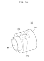
FIG. 3A is a perspective view illustrating a connector according to a first exemplary embodiment of the present invention; -
FIG. 3B is a cross-sectional view illustrating a dual pipe for heat exchange according to a first exemplary embodiment of the present invention; -
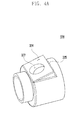
FIG. 4A is a perspective view illustrating a connector according to a second exemplary embodiment of the present invention; -
FIG. 4B is a perspective view illustrating coupling of a dual pipe for heat exchange according to a second exemplary embodiment of the present invention; -
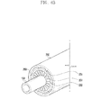
FIG. 5A is a perspective view illustrating a connector according to a third exemplary embodiment of the present invention; -
FIG. 5B is a perspective view illustrating coupling of a dual pipe for heat exchange according to a third exemplary embodiment of the present invention; -
FIG. 5C is a perspective view illustrating coupling of a dual pipe for heat exchange according to a third exemplary embodiment of the present invention; and -
FIGS. 6A and6B are perspective views illustrating coupling of an inner pipe and an outer pipe according to a fourth exemplary embodiment of the present invention. - Hereinafter, exemplary embodiments of the present invention are described in detail with reference to the accompanying drawings. The same reference numbers are used throughout the drawings to refer to the same or like parts. The views in the drawings are schematic views only, and are not intended to be to scale or correctly proportioned. Detailed descriptions of well-known functions and structures incorporated herein may be omitted to avoid obscuring the subject matter of the present invention.
-
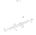
FIG. 1 is a perspective view illustrating a dual pipe for heat exchange according to an exemplary embodiment of the present invention. - Referring to
FIG. 1 , the dual pipe of the present exemplary embodiment includes aninner pipe 100,outer pipe 200, andconnector 300. - It is general that in an outer pipe flow channel formed between the
outer pipe 200 and theinner pipe 100, a refrigerant of a liquid state of a high temperature and a high pressure flows, and in an inner pipe flow channel formed in theinner pipe 100, a refrigerant of a gas state of a low temperature and a low pressure flows. The both fluids flow in an opposite direction and exchange a heat in an opposite type. - All of the
outer pipe 200,inner pipe 100, andconnector 300 have a section shape of a circular shape, but a section shape of theouter pipe 200,inner pipe 100, andconnector 300 is not limit thereto and can be formed in various polygonal shapes. -
FIG. 2 is a perspective view illustrating a coil typeinner pipe 100 according to a first exemplary embodiment of the present invention. - The
inner pipe 100 has acoil portion 112, and thecoil portion 112 is formed in a spring shape having a virtual circle therein. Thecoil portion 112 has a shape continuously including adjacent pipes due to a spring shape. The adjacent pipes may contact, but for appropriate heat exchange, it is preferable that adjacent pipes maintain a constant gap. When a distance between the centers of adjacent pipes is L and a diameter of an outer circumferential surface of theinner pipe 100 is R1, it is preferable that thecoil portion 112 satisfies 0.5 × R1 ≤ L and it is more preferable that thecoil portion 112 satisfies 0.5 × R1 ≤ L ≤ 3 × R1. Further, when an inner circumferential diameter of theouter pipe 200 is R2, it is preferable that thecoil portion 112 satisfies 2×R1 ≤ R2 ≤ 4×R1. - Because the
inner pipe 100 is formed in a coil shape, when bending exists in a piping portion of a heat exchanger, damage of the inner pipe can be prevented. Even if abnormal bending occurs, danger in which theinner pipe 100 is to be damaged reduces. Further, because a heat exchange area increases due to a coil shape and a fluid flowing to the outer pipe flow channel generates vortex, a heat exchange ability between both fluids is more excellent than that of an existing heat exchanger of a dual pipe. - An outermost portion of the
coil portion 112 of theinner pipe 100 generally contacts with an inner circumferential surface of theouter pipe 200. Thecoil portion 112 of theinner pipe 100 and an inner circumferential surface of theouter pipe 200 contact but do not bond. - The
outer pipe 200 is generally a cylindrical straight pipe. Theouter pipe 200 may be made of the same material as that of theinner pipe 100, but it is preferable that theouter pipe 200 is made of a heat insulating material for excellent heat exchange. Aconnector 310 is connected to both end portions of theouter pipe 200. Theinner pipe 100 is housed at the inside of theouter pipe 200, and thecoil portion 112 of theinner pipe 100 is housed at the inside of theouter pipe 200. Astraight pipe portion 111 of theinner pipe 100 is extended to the outside of theouter pipe 200 through both end portions of theouter pipe 200. Thestraight pipe portion 111 of theinner pipe 100 is further extended to be extended to the outside of the dual pipe through a throughhole 312 of theconnector 310. - At the
connector 310, theinner pipe 100 and theouter pipe 200 are coupled. Theconnector 310 includes an outerpipe connection portion 313, throughhole 312,fastening groove 311. - The outer
pipe connection portion 313 is coupled to theouter pipe 200. An outer circumferential surface of an end portion of theouter pipe 200 is inserted into the outerpipe connection portion 313, and an outer circumferential surface of an end portion of theouter pipe 200 and an inner circumferential surface of the outerpipe connection portion 313 contact. In order to prevent separation of theouter pipe 200, astopper 314 is formed at an inner circumferential surface of the outerpipe connection portion 313, and thestopper 314 generally has a ring shape formed along an inner circumferential surface of the outerpipe connection portion 313. However, thestopper 314 may have a pin shape or an intermittently formed plate shape. - The
outer pipe 200 and theconnector 310 are connected by a forced insertion method, but may be connected through welding or another fastening device. - The
inner pipe 100 is extended to the outside through the throughhole 312. Theinner pipe 100 is extended from the inside to the outside of the dual pipe, and an inner circumferential surface of the throughhole 312 surface contacts with an outer circumferential surface of theinner pipe 100. An inner circumferential surface of the throughhole 312 may be formed in a length direction and a vertical direction of the dual pipe, but in a first exemplary embodiment, the inner circumferential surface of the throughhole 312 is formed in an inclined direction instead of a vertical direction. An external pipe connection portion of conventional dual pipes was coupled in a length direction of the dual pipe or a direction perpendicular to a length direction of the dual pipe. There was a problem that the dual pipe occupies wide space due to such vertical coupling. In a dual pipe of a first exemplary embodiment, the throughhole 312 is formed to have an appropriate angle in a length direction of the dual pipe instead of vertical to a length direction of the dual pipe. It is preferable that a forming angle of the throughhole 312 is 30° to 60°. Theinner pipe 100 may be bent, and theinner pipe 100 extended to outside through the throughhole 312 may be bent parallel to a length direction of the dual pipe. A conventional dual pipe had a problem that should be bent by about 90°, however the present exemplary embodiment has a merit that a volume of the dual pipe reduces with only appropriate bending. For example, when an angle in which an inner circumferential surfaces of the throughhole 312 forms with a length direction of the dual pipe is 45°, by bending the inner pipe by 45°, theinner pipe 100 may be parallel to the dual pipe. - The through
hole 312 is generally formed in an outer circumferential surface of the connector, but it is preferable that a portion of an outer circumferential surface of the connector is processed in a horizontal surface in a surface shape to be parallel and is processed to position on thehorizontal surface 316. An end portion of thehorizontal surface 316 is formed toward thefastening groove 311, and the other end portion thereof is formed to contact with the firstvertical portion 315. The firstvertical portion 315 is formed in an outer circumferential surface direction of theconnector 310 from thehorizontal surface 316. - An external pipe is coupled to the
fastening groove 311 of the dual pipe. A diameter of thefastening groove 311 is smaller than that of theconnector 310. In order to constantly make a volume flow quantity of a fluid flowing to the inside of theouter pipe 200, it is preferable that widths that subtract an area of a section of theinner pipe 100 from areas of a section of the external pipe and a section of theouter pipe 200 are similar. Therefore, a diameter of thefastening groove 311 is generally smaller than that of theouter pipe 200. In an end portion of theconnector 310, a second vertical portion 317 formed in a constant length in a circle central direction exists, and a protruded portion 318 extended in a length direction of theconnector 310 from the second vertical portion 317 exists. An external pipe is connected to a protruded portion 318, and a fluid flowing to the outer pipe flow channel passes through the protruded portion 318 and flows to the external pipe. -
FIG. 4A is a perspective view illustrating a connector according to a second exemplary embodiment of the present invention, andFIG. 4B is a perspective view illustrating coupling of a dual pipe for heat exchange according to a second exemplary embodiment of the present invention. - The second exemplary embodiment of the present invention includes a modified configuration of a connector. An
outer pipe 200 and aninner pipe 100 are the same as those of the first exemplary embodiment. The second exemplary embodiment includes aninclined surface 324 instead of a horizontal surface. One end portion of theinclined surface 324 faces a fastening groove, and the other end portion thereof faces an outer pipe connection portion. An end portion of theinclined surface 324 facing the outer pipe connection portion has a shape protruded to the outside of aconnector 320. Because theinclined surface 324 has a shape protruded to the outside of the connector, an inner circumferential surface of a throughhole 322 may be formed to have a width greater than that of the first exemplary embodiment. Therefore, a contact area of theinner pipe 100 and the throughhole 322 is enlarged, and coupling reliability further improves. -
FIG. 5A is a perspective view illustrating a connector according to a third exemplary embodiment of the present invention,FIG. 5B is a perspective view illustrating coupling of a dual pipe for heat exchange according to a third exemplary embodiment of the present invention, andFIG. 5C is a perspective view illustrating coupling of a dual pipe for heat exchange according to a third exemplary embodiment of the present invention. - The third exemplary embodiment of the present invention includes a modified configuration of a connector. An
outer pipe 200 and aninner pipe 100 are the same as those of the first and second exemplary embodiments. - A
connector 330 includes apipe expander 336 enlarged in a direction of afastening groove 331 from an outer pipe connection portion. Thefastening groove 331 is formed on a secondvertical portion 337, as in the first and second exemplary embodiments, but a throughhole 332 is formed on the secondvertical portion 337, unlike the first and second exemplary embodiments. Because the throughhole 332 is formed on the secondvertical portion 337, after theinner pipe 100 is extended to the outside of the throughhole 332, theinner pipe 100 is not bent. Due to such a configuration, there is a merit that theconnector 330 can be easily produced and a volume of the dual pipe reduces. Although not shown inFIG. 5A , a protruded portion may exist. In the throughhole 332, for easy coupling to theinner pipe 100, it may be considered to form a protruded portion extended from the throughhole 332 to the outside. -
FIGS. 6A and6B are perspective views illustrating coupling of an inner pipe and an outer pipe according to a fourth exemplary embodiment of the present invention. - The fourth exemplary embodiment of the present invention includes a modified configuration of an
outer pipe 240 and aninner pipe 140. Theinner pipe 140 has a straight pipe shape instead of a coil shape. - A
partitioning wall 241 formed by protruding from an inner circumferential surface of theouter pipe 240 to an outer circumferential surface direction of theinner pipe 140 exists between theouter pipe 240 and theinner pipe 140. Thepartitioning wall 241 is extended in a length direction of theouter pipe 240 and is disposed at a predetermined gap in a circumference direction. Thepartitioning wall 241 is generally formed in a straight line in a length direction of theouter pipe 240, but for appropriate heat exchange, that it is preferable that thepartitioning wall 241 is extended in a spiral shape in a length direction of theouter pipe 240. - An
outer pipe 250 may have a shape of the dual pipe shown inFIG. 6B . In this case, the heat exchanger becomes a triple pipe heat exchanger. Anintermediate pipe 260 added to the inside of theouter pipe 250 is formed integrally with theouter pipe 250. Apartitioning wall 251 is formed between theouter pipe 250 and theintermediate pipe 260, andadditional partitioning walls intermediate pipe 260. The firstadditional partitioning wall 261 is formed at a position corresponding to thepartitioning wall 251 formed at an inner circumferential surface of theouter pipe 250. Further, the separate secondadditional partitioning wall 262 may be formed between the firstadditional partitioning wall 261. - The
outer pipes inner pipes inner pipes outer pipes partitioning wall 251 exists, a dual pipe can be produced. Theconnectors inner pipes holes - As described above, according to the present invention, by improving thermal conductivity of a refrigerant by a structure of a dual pipe, efficiency and performance of an air-conditioner system for a vehicle can be improved.
- By a structure of the dual pipe, a thickness of an outer pipe and an inner pipe can be minimized.
- By improving heat exchange efficiency by a heat exchanger having a dual pipe, cooling efficiency of a cooling system can be improved.
- Although exemplary embodiments of the present invention have been described in detail hereinabove, it should be clearly understood that many variations and modifications of the basic inventive concepts herein described, which may appear to those skilled in the art, will still fall within the spirit and scope of the exemplary embodiments of the present invention as defined in the appended claims.
Claims (6)
- A dual pipe for heat exchange, comprising:an inner pipe;an outer pipe formed separately from the inner pipe to house the inner pipe therein; anda connector coupled to the inner pipe and the outer pipe,wherein the connector comprises:an outer pipe connection portion for housing an end portion of the outer pipe therein;a fastening groove for fastening a supply pipe of a fluid supplied to a flow path formed between the outer pipe and the inner pipe;a stopper formed at an inner circumferential surface of the outer pipe connection portion; anda through hole having an inner circumferential surface contacting with an outer circumferential surface of the inner pipe,wherein the inner pipe is housed at the inside of the outer pipe, a coil portion is formed in a portion positioned at the inside of the outer pipe, a portion extended from the coil portion is extended from the inside to the outside of the connector through a through hole of the connector, and an outermost portion of the coil portion line contacts with an inner circumferential surface of the outer pipe.
- The dual pipe of claim 1, wherein the coil portion satisfies 0.5 × R1 ≤ L ≤ 3 × R1, when a distance between the centers of adjacent pipes is L, and a diameter of an outer circumferential surface of the inner pipe is R1, and, and
the coil portion satisfies 2 × R1 ≤ R2 ≤ 4 × R1, when an inner circumferential diameter of the outer pipe is R2. - The dual pipe of claim 2, wherein the connector comprises a horizontal surface that processes a portion of an outer circumferential surface of the connector in a surface shape in parallel,
a through hole is formed on the horizontal surface,
one end portion of the connector faces a fastening groove, and the other end portion thereof contacts with a first vertical portion, and
the first vertical portion is formed in an outer circumferential surface direction of the connector from the horizontal surface. - The dual pipe of claim 2, wherein the connector comprises an inclined surface in which one end portion faces a fastening groove and in which the other end portion faces an outer pipe connection portion, and
an end portion in which the inclined surface faces the outer pipe connection portion is protruded to the outside of the connector. - The dual pipe of claim 2, wherein the connector comprises a pipe extender formed in one end portion and has a vertical surface contacting with the pipe extender, and
the fastening groove and the through hole are formed at the vertical surface. - The dual pipe of claim 3, wherein the inner pipe, outer pipe, and connector are made of the same material.
Applications Claiming Priority (1)
| Application Number | Priority Date | Filing Date | Title |
|---|---|---|---|
| KR1020120098149A KR101249721B1 (en) | 2012-09-05 | 2012-09-05 | Dual pipe for heat exchange |
Publications (2)
| Publication Number | Publication Date |
|---|---|
| EP2706321A2 true EP2706321A2 (en) | 2014-03-12 |
| EP2706321A3 EP2706321A3 (en) | 2014-08-27 |
Family
ID=48442148
Family Applications (1)
| Application Number | Title | Priority Date | Filing Date |
|---|---|---|---|
| EP13181460.0A Withdrawn EP2706321A3 (en) | 2012-09-05 | 2013-08-23 | Dual pipe for heat exchange |
Country Status (5)
| Country | Link |
|---|---|
| US (1) | US9513061B2 (en) |
| EP (1) | EP2706321A3 (en) |
| JP (1) | JP5938021B2 (en) |
| KR (1) | KR101249721B1 (en) |
| CN (1) | CN103822411B (en) |
Cited By (2)
| Publication number | Priority date | Publication date | Assignee | Title |
|---|---|---|---|---|
| ITUB20153867A1 (en) * | 2015-09-24 | 2017-03-24 | Dytech Dynamic Fluid Tech S P A | JUNCTION FOR TUBES OF A MOTOR VEHICLE |
| EP3306248A1 (en) * | 2016-10-05 | 2018-04-11 | Hs R & A Co., Ltd. | Double pipe heat exchanger and method for manufacturing the same |
Families Citing this family (10)
| Publication number | Priority date | Publication date | Assignee | Title |
|---|---|---|---|---|
| US8640366B1 (en) | 2013-03-15 | 2014-02-04 | Friend Solberg | Military award attachment method and device |
| KR101607642B1 (en) * | 2015-07-24 | 2016-03-31 | 주식회사 유한엔지니어링 | Complex energy saving freezer and refrigerator |
| KR101584607B1 (en) * | 2015-07-24 | 2016-01-14 | 주식회사 유한엔지니어링 | Energy saving freezer and refrigerator having improved condensing ability |
| CN105115193A (en) * | 2015-10-10 | 2015-12-02 | 常州精励汽车科技有限公司 | Air conditioner heat regenerator for automobile |
| KR102007794B1 (en) * | 2017-12-08 | 2019-08-08 | 주식회사 화승알앤에이 | Noise reduction type double pipe heat exchanger |
| US11231212B2 (en) * | 2019-04-05 | 2022-01-25 | Johnson Controls Technology Company | Refrigerant discharge heat exchange system and method |
| KR102224118B1 (en) * | 2019-06-04 | 2021-03-09 | 주식회사 화승알앤에이 | Double pipe heat-exchanger with one body type connector |
| KR102256344B1 (en) * | 2020-03-10 | 2021-05-25 | 박정순 | refrigerant pipe structure |
| EP4113036A4 (en) * | 2020-03-12 | 2023-08-09 | Zhejiang Dunan Artificial Environment Co., Ltd. | Three-way pipe, heat exchanger, heat exchanger assembly and refrigeration apparatus |
| EP3964372A1 (en) * | 2020-09-03 | 2022-03-09 | TI Automotive Technology Center GmbH | Tube assembly for transporting temperature control media |
Citations (1)
| Publication number | Priority date | Publication date | Assignee | Title |
|---|---|---|---|---|
| JP2007107581A (en) * | 2005-10-12 | 2007-04-26 | Nissan Motor Co Ltd | Double tube branch structure and its manufacturing method |
Family Cites Families (36)
| Publication number | Priority date | Publication date | Assignee | Title |
|---|---|---|---|---|
| DE2236954A1 (en) * | 1971-07-27 | 1973-02-08 | Alfa Romeo Spa | HEAT EXCHANGER |
| JPS5846379B2 (en) | 1978-04-27 | 1983-10-15 | 新東工業株式会社 | Mold sprue production equipment using reduced pressure molding method |
| JPS5923964Y2 (en) * | 1979-10-14 | 1984-07-16 | ジヨ−ジ ハ−ツ | Sample cooler in boiler system |
| DE19903833A1 (en) * | 1999-02-01 | 2000-08-03 | Behr Gmbh & Co | Integrated collector heat exchanger assembly |
| DE19934346B4 (en) * | 1999-07-22 | 2005-10-13 | Rehau Ag + Co. | Device for fastening and sealing a heating element in a windscreen washer pipe |
| JP4257039B2 (en) * | 2001-02-06 | 2009-04-22 | カルソニックカンセイ株式会社 | Double pipe joint, Brazing method of double pipe joint and double pipe |
| US6866090B2 (en) | 2000-02-24 | 2005-03-15 | Calsonic Kansei Corporation | Air conditioning apparatus for vehicle |
| JP2001336833A (en) * | 2000-05-30 | 2001-12-07 | Takagi Ind Co Ltd | Heat exchanging method, heat exchanger and heat exchanging system |
| US6390137B1 (en) * | 2000-06-20 | 2002-05-21 | Ti Group Automotive Systems, Llc | Co-tube assembly for heating and air conditioning system |
| JP2004270916A (en) * | 2003-02-17 | 2004-09-30 | Calsonic Kansei Corp | Double pipe and its manufacturing method |
| US6920919B2 (en) * | 2003-03-24 | 2005-07-26 | Modine Manufacturing Company | Heat exchanger |
| JP3927920B2 (en) * | 2003-05-16 | 2007-06-13 | 日本ピラー工業株式会社 | Heat exchanger |
| JP3984928B2 (en) * | 2003-05-16 | 2007-10-03 | 日本ピラー工業株式会社 | Piping system for semiconductor manufacturing equipment |
| DE602004010950T2 (en) * | 2003-05-16 | 2008-12-24 | Nippon Pillar Packing Co., Ltd. | Tubular device and conduit system with such a device |
| JP4075732B2 (en) * | 2003-08-19 | 2008-04-16 | 松下電器産業株式会社 | Heat exchanger for heat pump water heater |
| JP4414197B2 (en) * | 2003-11-18 | 2010-02-10 | 株式会社ティラド | Double tube heat exchanger |
| US7661460B1 (en) * | 2003-12-18 | 2010-02-16 | Advanced Thermal Sciences Corp. | Heat exchangers for fluid media |
| JP2006003071A (en) * | 2004-05-20 | 2006-01-05 | Showa Denko Kk | Heat exchanger |
| JP2005345034A (en) * | 2004-06-04 | 2005-12-15 | Matsushita Electric Ind Co Ltd | Heat exchanger and heat pump water heater using it |
| JP4029092B2 (en) * | 2004-10-26 | 2008-01-09 | 日本ピラー工業株式会社 | Fluid heater and fluid heating device |
| JP4387974B2 (en) * | 2005-04-25 | 2009-12-24 | パナソニック株式会社 | Refrigeration cycle equipment |
| JP2007032949A (en) * | 2005-07-28 | 2007-02-08 | Showa Denko Kk | Heat exchanger |
| JP4864439B2 (en) * | 2005-12-06 | 2012-02-01 | 株式会社デンソー | Double tube and manufacturing method thereof |
| JP4664203B2 (en) * | 2005-12-27 | 2011-04-06 | カルソニックカンセイ株式会社 | Double pipe joint structure |
| JP4698417B2 (en) * | 2005-12-28 | 2011-06-08 | 株式会社デンソー | Manufacturing method of double pipe |
| JP2008164245A (en) * | 2006-12-28 | 2008-07-17 | Kobelco & Materials Copper Tube Inc | Heat exchanger |
| JP2008209074A (en) * | 2007-02-27 | 2008-09-11 | Soichi Mizui | Multi-tubular heat exchanger |
| DE102007033166A1 (en) * | 2007-07-17 | 2009-01-22 | WTS Kereskedelmi és Szolgáltató Kft. | heat exchangers |
| US9587888B2 (en) * | 2008-07-24 | 2017-03-07 | Mahle International Gmbh | Internal heat exchanger assembly |
| JP5157811B2 (en) * | 2008-10-15 | 2013-03-06 | 株式会社デンソー | Pipe fitting |
| WO2010051333A1 (en) * | 2008-10-29 | 2010-05-06 | Delphi Technologies, Inc. | Internal heat exchanger assembly having an internal bleed valve assembly |
| FR2939878B1 (en) * | 2008-12-17 | 2011-02-04 | Hutchinson | INTERNAL THERMAL EXCHANGER FOR A MOTOR VEHICLE AIR CONDITIONING CIRCUIT, SUCH A CIRCUIT AND METHOD FOR CONNECTING A CONNECTOR TO THE EXCHANGER |
| JP3157975U (en) * | 2009-09-18 | 2010-03-11 | 豊彦 浦川 | Double-pipe heat exchanger for continuous heating of high-concentration natural carbonated spring that minimizes carbon dioxide escape |
| KR20110052889A (en) * | 2009-11-13 | 2011-05-19 | 주식회사 효성 | Dual type heat exchanger |
| KR101166806B1 (en) * | 2010-03-05 | 2012-07-31 | 주식회사 화승알앤에이 | Double pipe and heat exchanger having the same |
| WO2012024606A1 (en) * | 2010-08-20 | 2012-02-23 | Turbotec Products, Inc. | Connector for tube-in-tube heat exchanger and methods of making and using same |
-
2012
- 2012-09-05 KR KR1020120098149A patent/KR101249721B1/en active IP Right Grant
-
2013
- 2013-08-23 EP EP13181460.0A patent/EP2706321A3/en not_active Withdrawn
- 2013-08-27 JP JP2013175821A patent/JP5938021B2/en not_active Expired - Fee Related
- 2013-09-03 CN CN201310394888.7A patent/CN103822411B/en active Active
- 2013-09-05 US US14/019,138 patent/US9513061B2/en active Active
Patent Citations (1)
| Publication number | Priority date | Publication date | Assignee | Title |
|---|---|---|---|---|
| JP2007107581A (en) * | 2005-10-12 | 2007-04-26 | Nissan Motor Co Ltd | Double tube branch structure and its manufacturing method |
Cited By (4)
| Publication number | Priority date | Publication date | Assignee | Title |
|---|---|---|---|---|
| ITUB20153867A1 (en) * | 2015-09-24 | 2017-03-24 | Dytech Dynamic Fluid Tech S P A | JUNCTION FOR TUBES OF A MOTOR VEHICLE |
| WO2017051382A1 (en) * | 2015-09-24 | 2017-03-30 | Dytech - Dynamic Fluid Technologies S.P.A. | Connection for tubes of a motor vehicle |
| EP3306248A1 (en) * | 2016-10-05 | 2018-04-11 | Hs R & A Co., Ltd. | Double pipe heat exchanger and method for manufacturing the same |
| US11067340B2 (en) | 2016-10-05 | 2021-07-20 | HS R & A Co., Ltd | Double pipe heat exchanger and method for manufacturing the same |
Also Published As
| Publication number | Publication date |
|---|---|
| US9513061B2 (en) | 2016-12-06 |
| JP2014052176A (en) | 2014-03-20 |
| KR101249721B1 (en) | 2013-04-02 |
| CN103822411A (en) | 2014-05-28 |
| US20140060786A1 (en) | 2014-03-06 |
| CN103822411B (en) | 2016-06-15 |
| EP2706321A3 (en) | 2014-08-27 |
| JP5938021B2 (en) | 2016-06-22 |
Similar Documents
| Publication | Publication Date | Title |
|---|---|---|
| US9513061B2 (en) | Dual pipe for heat exchange | |
| EP2363675A2 (en) | Double pipe and heat exchanger having the same | |
| CN102959353B (en) | Multichannel tubes with deformable webs | |
| US20060096314A1 (en) | Double-wall pipe and refrigerant cycle device using the same | |
| JP2007032949A (en) | Heat exchanger | |
| US20060213220A1 (en) | Vehicular air-conditioner | |
| KR101797176B1 (en) | Dual pipe structure for internal heat exchanger | |
| KR20100011918A (en) | Internal heat exchanger assembly | |
| KR20080063150A (en) | Heat exchanger | |
| CN103836843A (en) | Internal heat exchanger for an air conditioning system | |
| JP2009041798A (en) | Heat exchanger | |
| JP5898892B2 (en) | Intermediate heat exchanger | |
| GB2508842A (en) | Double wall tube heat exchanger | |
| EP2796822B1 (en) | Air conditioner | |
| KR102224118B1 (en) | Double pipe heat-exchanger with one body type connector | |
| KR20160083440A (en) | Multiple pipe for refrigerator exchanger | |
| KR20140111382A (en) | Air conditioning system for automotive vehicles | |
| KR101314859B1 (en) | A method for manufacturing a heat exchanger | |
| CN217464935U (en) | Cascade refrigerating system and refrigerator | |
| WO2013122451A1 (en) | Outdoor unit of an air-conditioning apparatus | |
| JP7211606B2 (en) | Condensers, cooling systems, and fittings | |
| KR20160119378A (en) | Double pipe heat-exchanger with one body type connector | |
| KR20060076840A (en) | Header tank for heat exchanger for high pressure | |
| KR101096465B1 (en) | Header tank for heat exchanger | |
| US20190145667A1 (en) | Heat exchange device, refrigeration system, and heat exchange method |
Legal Events
| Date | Code | Title | Description |
|---|---|---|---|
| PUAI | Public reference made under article 153(3) epc to a published international application that has entered the european phase |
Free format text: ORIGINAL CODE: 0009012 |
|
| AK | Designated contracting states |
Kind code of ref document: A2 Designated state(s): AL AT BE BG CH CY CZ DE DK EE ES FI FR GB GR HR HU IE IS IT LI LT LU LV MC MK MT NL NO PL PT RO RS SE SI SK SM TR |
|
| AX | Request for extension of the european patent |
Extension state: BA ME |
|
| PUAL | Search report despatched |
Free format text: ORIGINAL CODE: 0009013 |
|
| AK | Designated contracting states |
Kind code of ref document: A3 Designated state(s): AL AT BE BG CH CY CZ DE DK EE ES FI FR GB GR HR HU IE IS IT LI LT LU LV MC MK MT NL NO PL PT RO RS SE SI SK SM TR |
|
| AX | Request for extension of the european patent |
Extension state: BA ME |
|
| RIC1 | Information provided on ipc code assigned before grant |
Ipc: F28D 7/10 20060101ALI20140718BHEP Ipc: F28D 7/02 20060101ALI20140718BHEP Ipc: F28F 9/02 20060101AFI20140718BHEP |
|
| 17P | Request for examination filed |
Effective date: 20150223 |
|
| RBV | Designated contracting states (corrected) |
Designated state(s): AL AT BE BG CH CY CZ DE DK EE ES FI FR GB GR HR HU IE IS IT LI LT LU LV MC MK MT NL NO PL PT RO RS SE SI SK SM TR |
|
| 17Q | First examination report despatched |
Effective date: 20161125 |
|
| STAA | Information on the status of an ep patent application or granted ep patent |
Free format text: STATUS: THE APPLICATION IS DEEMED TO BE WITHDRAWN |
|
| 18D | Application deemed to be withdrawn |
Effective date: 20170915 |