EP2706291A1 - Verstellbare Stütze für Lichtquellen - Google Patents
Verstellbare Stütze für Lichtquellen Download PDFInfo
- Publication number
- EP2706291A1 EP2706291A1 EP13181897.3A EP13181897A EP2706291A1 EP 2706291 A1 EP2706291 A1 EP 2706291A1 EP 13181897 A EP13181897 A EP 13181897A EP 2706291 A1 EP2706291 A1 EP 2706291A1
- Authority
- EP
- European Patent Office
- Prior art keywords
- toothed
- support element
- support
- mounting
- orientation
- Prior art date
- Legal status (The legal status is an assumption and is not a legal conclusion. Google has not performed a legal analysis and makes no representation as to the accuracy of the status listed.)
- Granted
Links
- 230000005855 radiation Effects 0.000 claims abstract description 22
- 238000000605 extraction Methods 0.000 claims description 2
- 230000008878 coupling Effects 0.000 claims 2
- 238000010168 coupling process Methods 0.000 claims 2
- 238000005859 coupling reaction Methods 0.000 claims 2
- 230000015572 biosynthetic process Effects 0.000 description 12
- 238000000034 method Methods 0.000 description 2
- 230000006835 compression Effects 0.000 description 1
- 238000007906 compression Methods 0.000 description 1
- 230000010355 oscillation Effects 0.000 description 1
- 230000002459 sustained effect Effects 0.000 description 1
Images


Classifications
-
- F—MECHANICAL ENGINEERING; LIGHTING; HEATING; WEAPONS; BLASTING
- F21—LIGHTING
- F21S—NON-PORTABLE LIGHTING DEVICES; SYSTEMS THEREOF; VEHICLE LIGHTING DEVICES SPECIALLY ADAPTED FOR VEHICLE EXTERIORS
- F21S8/00—Lighting devices intended for fixed installation
- F21S8/02—Lighting devices intended for fixed installation of recess-mounted type, e.g. downlighters
- F21S8/028—Lighting devices intended for fixed installation of recess-mounted type, e.g. downlighters being retractable, i.e. having two fixed positions, one recessed, e.g. in a wall, floor or ceiling, and one extended when in use
-
- F—MECHANICAL ENGINEERING; LIGHTING; HEATING; WEAPONS; BLASTING
- F21—LIGHTING
- F21V—FUNCTIONAL FEATURES OR DETAILS OF LIGHTING DEVICES OR SYSTEMS THEREOF; STRUCTURAL COMBINATIONS OF LIGHTING DEVICES WITH OTHER ARTICLES, NOT OTHERWISE PROVIDED FOR
- F21V21/00—Supporting, suspending, or attaching arrangements for lighting devices; Hand grips
- F21V21/14—Adjustable mountings
- F21V21/30—Pivoted housings or frames
Definitions
- the present description relates to supports for lighting sources.
- Various embodiments can relate to orientable supports for lighting sources, such as recessed lighting sources.
- Various embodiments can relate to orientable supports for LED lighting sources.
- an embodiment in the context of this description indicates that a particular configuration, structure or feature described in relation to the embodiment is included in at least one embodiment. Therefore, phrases such as "in one embodiment", which may occur at various points in this description, do not necessarily refer to the same embodiment. Moreover, particular forms, structures or features may be combined in any suitable manner in one or more embodiments.
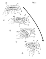
- Figure 1 shows a possible orientation sequence for a lighting source 10, for example an LED lighting source.
- the lighting source 10 can be a recessed lighting source, for example for mounting in a false ceiling S.
- the lighting source 10 can include, as the light radiation source L, an LED source, for example an LED spotlight.
- the light radiation source L can be of a different type. It will be understood moreover that the light radiation source L may in itself not form part of the embodiments which refer primarily to the adjustable support of the light radiation source L.
- a support of this type can include:
- the mounting element 12 and the support element 14 are hinged to one another (like a book).
- a mechanism 16 makes it possible to control and adjust the orientation movement of the support element 14 with respect to the mounting element 12 about an orientation axis X16 (see figure 2 ).
- the mounting element 12 is mounted on the false ceiling S (mounting surface) and the light radiation source L is carried by the support element 14.
- the position adopted by the support element 14 with respect to the mounting element 12 about the axis X16 that is the angle of aperture of the ideal dihedron formed by the support element 14 and by the mounting element 12, hinged to one another like a book
- this can take place by acting, for example with a finger, on a drive element 160, which is accessible from the outside, for example, in that it is left uncovered by the support element 14.
- a drive element 160 which is accessible from the outside, for example, in that it is left uncovered by the support element 14.
- the drive element 160 it is possible to ensure that the support element 14 (and the light radiation source L mounted thereon) can move downward, so as to vary the direction of the light radiation.
- the angle which is adopted by the support element 14 with respect to the mounting element 12 (and therefore the direction of the light radiation emitted by the source L) can be adjusted into the desired position by making the support element 14 move down or back up with respect to the mounting element 12.
- both the mounting element 12 and the support element 14 have an on the whole annular shape, with the support element 14 (on the inside of which the light radiation source L is mounted) having smaller radial dimensions than the mounting element 12, which therefore surrounds the support element 14.
- the support element 14 can have an on the whole tubular structure with a spoon shape (see for example both figure 1 and figure 2 and also figures 9 to 11 ), with a tubular configuration curved according to an arcuate trajectory centered about the axis X16.
- the mechanism 16 can include various elements shown in greater detail in figures 3 to 8 .
- Figure 3 shows an annular body 140 which can form, in various embodiments, a type of ring-shaped rib of the support element 14.
- the rib ring 140 can be formed in one piece with the support element 14, even in the case in which the latter has a tubular spoon-like general configuration, as shown.
- the ring 140 can have, for example, two clamps 140a, which implement the hinging of the support element 14 with respect to the mounting element 12 so as to allow the relative orientation about the axis X16.
- the ring 140 can be situated in a slightly withdrawn or "recessed" position with respect to the plane of the mouth of the support element 14, the mouth rim of which is usually situated along the outline of the mouth opening of the light radiation source L.
- the mechanism 16 can include a double toothed sector 180 with a first toothed sector 180a and a second toothed sector 180b, which are arranged side by side and are intended to extend with their arcuate trajectories (for example with that of the first toothed sector 180a having a greater radius than that of the second toothed sector 180b) centered about the axis X16.
- a toothed actuator 200 which can have a rocker arm general structure and/or a fork shape such that it can be located astride the double toothed sector 180.
- the actuator 200 can have a tooth formation (single or multiple) 202 intended to cooperate (for example by a mechanism which can be grossly assimilated with a ratchet) with the first toothed sector 180a.
- an elastic means such as a spring 220, which is intended to elastically bias the toothed actuator 200 in the state in which the toothed formation 202 is in engagement with the first toothed sector 180a.
- the spring can act in compression between an arm of the actuator 200 which carries the tooth formation 202 and a bracket 140b protruding from the ring 140.
- a damper device 240 including a toothed wheel 242, which is intended to mesh with the second toothed sector 180b and is mounted on a support 244 so as to be able to rotate with respect to said support 244 with a rotational movement which is braked, for example by a general friction mechanism: rotary dampers of this type are known in the art and therefore there is no need to provide a detailed description at this point.
- the damper device 240 too can be mounted on a bracket 140c protruding from the ring 140 (see figure 3 ), in such a way as to make the toothed wheel 242 mesh with the toothed sector 180b, as shown schematically by dashed lines in figures 9 to 11 .
- the various elements which form the mechanism 16 as shown in figures 3 to 8 can be regarded as ideally subdivided into two sets of mutually cooperating elements which are intended to be mounted, respectively, on one or on the other of the mounting element 12 and the support element 14.
- the first set of cooperating elements may include essentially the double toothed sector 180, which, in the exemplary embodiments under consideration here, is assumed to be mounted on the mounting element 12, and therefore in a fixed position with respect to the orientation movement of the support element 14 (and therefore of the light radiation source L) exemplified in the accompanying drawings.
- the second set of cooperating elements can include, carried by the support element 14 in the exemplary embodiments under consideration here:
- the toothed actuator 200 can have two lateral pins 204 received in two recesses 140d of the ring 140. All of this in such a way that the actuator 200 is arranged with the bottom tongs of its fork shape located astride the double toothed sector 180 (mounted on the mounting element 12), having its toothed formation 202 facing the first toothed sector 180a.
- the drive element 160 associated with the actuator 200 can have an approximately arcuate profile, which allows for mounting on the mouth rim of the support element 14 in states in which the latter is accessible from the outside, as shown exactly in figure 1 .
- the drive element 160 too has opposing pins 162 (only one of which can be seen in figure 7 ), which allow for the hinging on the body of the support element 14 in such a way that an action exerted on the drive element 160 in the sense of making it rotate with respect to the support element 14 translates into an urging action exerted by teeth 164 carried by said drive element 160 counter to the actuator 200 (for example counter to the prongs of the fork shape); all of this with the result of making the closure member 200 oscillate about the pins 204 with a resultant departure and disengagement of the toothed formation 202 from the toothed sector 180a.
- Figure 9 can be regarded as ideally corresponding to the state shown in part a) of figure 1 , i.e. with the mouth rim of the support element 14 extending in coplanar states with respect to the mounting element 12.
- the state shown in part a) at the top in figure 9 relates to states in which the elastic action of the spring 220 urges the toothed formation 202 of the closure member into engagement against the toothed sector 180a.
- the orientation movement of the support element 14 (and of the light radiation source carried thereby) with respect to the mounting element 12 (and therefore with respect to the mounting surface, for example the false ceiling S) is prevented or at least opposed.
- the user can act on the drive element 160 - as shown schematically in the sequence of parts a) and b) of figure 1 - in such a way as to determine the oscillation in the direction which makes the pins 164 act on the tongs of the fork shape of the actuator 200. All of this while making the actuator 200 oscillate in the direction (counterclockwise, according to the point of view of figures 9 to 11 ) which makes the toothed formation 202 of the closure member 200 move away from the toothed sector 180a, disengaging it.
- the support element 14 can thus oscillate about the axis X16 and be oriented with respect to the mounting element 12 as shown schematically, for example, in part a) of figure 10 .
- the orientation movement can be blocked in any desired position (see for example figure 10b ) by simply releasing the drive element 160 so as to bring about, under the action of the spring 220, the return of the toothed formation 202 of the actuator 200 into the position of engagement with the toothed sector 180a. All of this while therefore restoring the state in which the orientation movement of the support element 14 with respect to the mounting element 12 is opposed by the engagement of the toothed formation 202 with the toothed sector 180a.
- the modes of operation described above allow the user to precisely adjust the position of orientation.
- the damper element 240 with the braked toothed wheel 242 which meshes with the toothed sector 180b, ensures that the orientation movement described is effected in a gradual and braked manner, avoiding for example undesired and unexpected returns of the support element 14 outside the mounting element 12.
- the profile of the toothing of the first toothed sector 180a can be realized with an asymmetric sawtooth profile, so as to give rise, in connection with the toothed formation 202 of the actuator 200, to a type of ratchet. This is the case in order to realize an action to counter the orientation movement of the support element 14 with respect to the mounting element 12 which is differentiated in both directions, for example countering the extraction movement of the support element 14 with respect to the mounting element 12 to a more pronounced extent than the orientation movement in the opposite direction.
- this differentiated countering action can, for example, make it possible to obtain the return of the support element 14 to the inside of the mounting element 12 (that is in the angular state shown in part a) of figure 1 ) with a simple pressing action exerted on the support element 14, without necessarily having to act on the drive element 160.
Landscapes
- Engineering & Computer Science (AREA)
- General Engineering & Computer Science (AREA)
- Non-Portable Lighting Devices Or Systems Thereof (AREA)
Applications Claiming Priority (1)
| Application Number | Priority Date | Filing Date | Title |
|---|---|---|---|
| ITTO20120766 | 2012-09-05 |
Publications (2)
| Publication Number | Publication Date |
|---|---|
| EP2706291A1 true EP2706291A1 (de) | 2014-03-12 |
| EP2706291B1 EP2706291B1 (de) | 2015-07-15 |
Family
ID=46939880
Family Applications (1)
| Application Number | Title | Priority Date | Filing Date |
|---|---|---|---|
| EP13181897.3A Not-in-force EP2706291B1 (de) | 2012-09-05 | 2013-08-27 | Verstellbare Stütze für Lichtquellen |
Country Status (2)
| Country | Link |
|---|---|
| EP (1) | EP2706291B1 (de) |
| CN (1) | CN103672795A (de) |
Cited By (1)
| Publication number | Priority date | Publication date | Assignee | Title |
|---|---|---|---|---|
| CN115507316A (zh) * | 2022-09-15 | 2022-12-23 | 中山泰腾照明有限公司 | 可上下摆动调节角度的灯具 |
Families Citing this family (1)
| Publication number | Priority date | Publication date | Assignee | Title |
|---|---|---|---|---|
| CN106439557B (zh) * | 2016-10-21 | 2018-05-15 | 苏州瑞腾照明科技股份有限公司 | 一种灯体可转动的照明灯 |
Citations (3)
| Publication number | Priority date | Publication date | Assignee | Title |
|---|---|---|---|---|
| EP0736729A1 (de) * | 1995-04-05 | 1996-10-09 | TARGETTI SANKEY S.p.A. | Orientierungsvorrichtung zum Hand- und Motorverstellen eines Beleuchtungsgeräts |
| DE29916102U1 (de) * | 1999-09-14 | 2000-02-24 | Sidler GmbH & Co, 72072 Tübingen | Leuchtenanordnung |
| US20080055905A1 (en) * | 2006-08-29 | 2008-03-06 | Shin-Yung Chiu | Ship-borne searchlight |
Family Cites Families (4)
| Publication number | Priority date | Publication date | Assignee | Title |
|---|---|---|---|---|
| DE10145499A1 (de) * | 2001-09-14 | 2003-04-03 | Zumtobel Staff Gmbh & Co Kg | Lichtkanalsystem |
| CN2600707Y (zh) * | 2002-12-12 | 2004-01-21 | 吴文彰 | 灯具分离快速自组构造 |
| CN201892063U (zh) * | 2010-10-15 | 2011-07-06 | 张国鸿 | 灯具 |
| CN102278721A (zh) * | 2011-04-22 | 2011-12-14 | 谢传坤 | 一种升降电杆 |
-
2013
- 2013-08-27 EP EP13181897.3A patent/EP2706291B1/de not_active Not-in-force
- 2013-09-04 CN CN201310398164.XA patent/CN103672795A/zh active Pending
Patent Citations (3)
| Publication number | Priority date | Publication date | Assignee | Title |
|---|---|---|---|---|
| EP0736729A1 (de) * | 1995-04-05 | 1996-10-09 | TARGETTI SANKEY S.p.A. | Orientierungsvorrichtung zum Hand- und Motorverstellen eines Beleuchtungsgeräts |
| DE29916102U1 (de) * | 1999-09-14 | 2000-02-24 | Sidler GmbH & Co, 72072 Tübingen | Leuchtenanordnung |
| US20080055905A1 (en) * | 2006-08-29 | 2008-03-06 | Shin-Yung Chiu | Ship-borne searchlight |
Cited By (1)
| Publication number | Priority date | Publication date | Assignee | Title |
|---|---|---|---|---|
| CN115507316A (zh) * | 2022-09-15 | 2022-12-23 | 中山泰腾照明有限公司 | 可上下摆动调节角度的灯具 |
Also Published As
| Publication number | Publication date |
|---|---|
| CN103672795A (zh) | 2014-03-26 |
| EP2706291B1 (de) | 2015-07-15 |
Similar Documents
| Publication | Publication Date | Title |
|---|---|---|
| US8215805B2 (en) | Hot aimable lamp assembly with memory for adjustable recessed light | |
| US7303327B2 (en) | Directionally controllable night light | |
| US8657464B2 (en) | Multiple mode light emitting device | |
| EP3132195B1 (de) | Beleuchtungshalterung | |
| TW201040446A (en) | Light emitting device and luminaire | |
| EP2706291B1 (de) | Verstellbare Stütze für Lichtquellen | |
| US10514154B2 (en) | Multisource beam shaping system | |
| EP2428720A2 (de) | Beleuchtungskörper | |
| USD946197S1 (en) | Pendant for decorative light fixtures | |
| HK1223675A1 (zh) | 角度可调节的灯具 | |
| US20090284975A1 (en) | Lighting Device With Magnetic Attraction System for Orienting the Light Beam | |
| CN210411312U (zh) | 一种调节机构及花洒移动组 | |
| JP7216747B2 (ja) | 長手方向軸線周りの回転用ラック付き電動式埋込型スポットライト | |
| JP5700159B1 (ja) | 照明装置 | |
| KR20120140353A (ko) | 거리조정수단을 갖는 램프장치 | |
| US9885460B2 (en) | Light assembly | |
| EP2706284B1 (de) | Montagesystem für Beleuchtungsvorrichtungen und entsprechende Vorrichtung | |
| US9664345B2 (en) | Task lamp | |
| USD880015S1 (en) | Reflector for a light bulb | |
| JP3229479U (ja) | シーリングランプ | |
| CN103930717A (zh) | 安装组件 | |
| JP3200833U (ja) | 自動開閉機能付き照明器具 | |
| KR20190090165A (ko) | 각도조절 조명 스탠드 | |
| CN109506170A (zh) | 一种升降投影灯 | |
| CN207334281U (zh) | 照明装置 |
Legal Events
| Date | Code | Title | Description |
|---|---|---|---|
| PUAI | Public reference made under article 153(3) epc to a published international application that has entered the european phase |
Free format text: ORIGINAL CODE: 0009012 |
|
| AK | Designated contracting states |
Kind code of ref document: A1 Designated state(s): AL AT BE BG CH CY CZ DE DK EE ES FI FR GB GR HR HU IE IS IT LI LT LU LV MC MK MT NL NO PL PT RO RS SE SI SK SM TR |
|
| AX | Request for extension of the european patent |
Extension state: BA ME |
|
| 17P | Request for examination filed |
Effective date: 20140912 |
|
| RBV | Designated contracting states (corrected) |
Designated state(s): AL AT BE BG CH CY CZ DE DK EE ES FI FR GB GR HR HU IE IS IT LI LT LU LV MC MK MT NL NO PL PT RO RS SE SI SK SM TR |
|
| RIC1 | Information provided on ipc code assigned before grant |
Ipc: F21V 21/30 20060101AFI20150217BHEP Ipc: F21S 8/02 20060101ALI20150217BHEP |
|
| GRAP | Despatch of communication of intention to grant a patent |
Free format text: ORIGINAL CODE: EPIDOSNIGR1 |
|
| INTG | Intention to grant announced |
Effective date: 20150407 |
|
| GRAS | Grant fee paid |
Free format text: ORIGINAL CODE: EPIDOSNIGR3 |
|
| GRAA | (expected) grant |
Free format text: ORIGINAL CODE: 0009210 |
|
| AK | Designated contracting states |
Kind code of ref document: B1 Designated state(s): AL AT BE BG CH CY CZ DE DK EE ES FI FR GB GR HR HU IE IS IT LI LT LU LV MC MK MT NL NO PL PT RO RS SE SI SK SM TR |
|
| REG | Reference to a national code |
Ref country code: CH Ref legal event code: EP Ref country code: GB Ref legal event code: FG4D |
|
| REG | Reference to a national code |
Ref country code: IE Ref legal event code: FG4D |
|
| REG | Reference to a national code |
Ref country code: AT Ref legal event code: REF Ref document number: 736990 Country of ref document: AT Kind code of ref document: T Effective date: 20150815 |
|
| REG | Reference to a national code |
Ref country code: DE Ref legal event code: R096 Ref document number: 602013002287 Country of ref document: DE |
|
| REG | Reference to a national code |
Ref country code: CH Ref legal event code: NV Representative=s name: BOVARD AG, CH |
|
| REG | Reference to a national code |
Ref country code: NL Ref legal event code: MP Effective date: 20150715 |
|
| REG | Reference to a national code |
Ref country code: LT Ref legal event code: MG4D |
|
| PG25 | Lapsed in a contracting state [announced via postgrant information from national office to epo] |
Ref country code: FI Free format text: LAPSE BECAUSE OF FAILURE TO SUBMIT A TRANSLATION OF THE DESCRIPTION OR TO PAY THE FEE WITHIN THE PRESCRIBED TIME-LIMIT Effective date: 20150715 Ref country code: LV Free format text: LAPSE BECAUSE OF FAILURE TO SUBMIT A TRANSLATION OF THE DESCRIPTION OR TO PAY THE FEE WITHIN THE PRESCRIBED TIME-LIMIT Effective date: 20150715 Ref country code: GR Free format text: LAPSE BECAUSE OF FAILURE TO SUBMIT A TRANSLATION OF THE DESCRIPTION OR TO PAY THE FEE WITHIN THE PRESCRIBED TIME-LIMIT Effective date: 20151016 Ref country code: NO Free format text: LAPSE BECAUSE OF FAILURE TO SUBMIT A TRANSLATION OF THE DESCRIPTION OR TO PAY THE FEE WITHIN THE PRESCRIBED TIME-LIMIT Effective date: 20151015 Ref country code: LT Free format text: LAPSE BECAUSE OF FAILURE TO SUBMIT A TRANSLATION OF THE DESCRIPTION OR TO PAY THE FEE WITHIN THE PRESCRIBED TIME-LIMIT Effective date: 20150715 |
|
| PG25 | Lapsed in a contracting state [announced via postgrant information from national office to epo] |
Ref country code: HR Free format text: LAPSE BECAUSE OF FAILURE TO SUBMIT A TRANSLATION OF THE DESCRIPTION OR TO PAY THE FEE WITHIN THE PRESCRIBED TIME-LIMIT Effective date: 20150715 Ref country code: PT Free format text: LAPSE BECAUSE OF FAILURE TO SUBMIT A TRANSLATION OF THE DESCRIPTION OR TO PAY THE FEE WITHIN THE PRESCRIBED TIME-LIMIT Effective date: 20151116 Ref country code: ES Free format text: LAPSE BECAUSE OF FAILURE TO SUBMIT A TRANSLATION OF THE DESCRIPTION OR TO PAY THE FEE WITHIN THE PRESCRIBED TIME-LIMIT Effective date: 20150715 Ref country code: SE Free format text: LAPSE BECAUSE OF FAILURE TO SUBMIT A TRANSLATION OF THE DESCRIPTION OR TO PAY THE FEE WITHIN THE PRESCRIBED TIME-LIMIT Effective date: 20150715 Ref country code: PL Free format text: LAPSE BECAUSE OF FAILURE TO SUBMIT A TRANSLATION OF THE DESCRIPTION OR TO PAY THE FEE WITHIN THE PRESCRIBED TIME-LIMIT Effective date: 20150715 Ref country code: RS Free format text: LAPSE BECAUSE OF FAILURE TO SUBMIT A TRANSLATION OF THE DESCRIPTION OR TO PAY THE FEE WITHIN THE PRESCRIBED TIME-LIMIT Effective date: 20150715 |
|
| REG | Reference to a national code |
Ref country code: DE Ref legal event code: R097 Ref document number: 602013002287 Country of ref document: DE |
|
| PG25 | Lapsed in a contracting state [announced via postgrant information from national office to epo] |
Ref country code: EE Free format text: LAPSE BECAUSE OF FAILURE TO SUBMIT A TRANSLATION OF THE DESCRIPTION OR TO PAY THE FEE WITHIN THE PRESCRIBED TIME-LIMIT Effective date: 20150715 Ref country code: SK Free format text: LAPSE BECAUSE OF FAILURE TO SUBMIT A TRANSLATION OF THE DESCRIPTION OR TO PAY THE FEE WITHIN THE PRESCRIBED TIME-LIMIT Effective date: 20150715 Ref country code: CZ Free format text: LAPSE BECAUSE OF FAILURE TO SUBMIT A TRANSLATION OF THE DESCRIPTION OR TO PAY THE FEE WITHIN THE PRESCRIBED TIME-LIMIT Effective date: 20150715 Ref country code: MC Free format text: LAPSE BECAUSE OF FAILURE TO SUBMIT A TRANSLATION OF THE DESCRIPTION OR TO PAY THE FEE WITHIN THE PRESCRIBED TIME-LIMIT Effective date: 20150715 Ref country code: DK Free format text: LAPSE BECAUSE OF FAILURE TO SUBMIT A TRANSLATION OF THE DESCRIPTION OR TO PAY THE FEE WITHIN THE PRESCRIBED TIME-LIMIT Effective date: 20150715 |
|
| PLBE | No opposition filed within time limit |
Free format text: ORIGINAL CODE: 0009261 |
|
| STAA | Information on the status of an ep patent application or granted ep patent |
Free format text: STATUS: NO OPPOSITION FILED WITHIN TIME LIMIT |
|
| PG25 | Lapsed in a contracting state [announced via postgrant information from national office to epo] |
Ref country code: RO Free format text: LAPSE BECAUSE OF FAILURE TO SUBMIT A TRANSLATION OF THE DESCRIPTION OR TO PAY THE FEE WITHIN THE PRESCRIBED TIME-LIMIT Effective date: 20150715 |
|
| REG | Reference to a national code |
Ref country code: IE Ref legal event code: MM4A |
|
| 26N | No opposition filed |
Effective date: 20160418 |
|
| PG25 | Lapsed in a contracting state [announced via postgrant information from national office to epo] |
Ref country code: IS Free format text: LAPSE BECAUSE OF FAILURE TO SUBMIT A TRANSLATION OF THE DESCRIPTION OR TO PAY THE FEE WITHIN THE PRESCRIBED TIME-LIMIT Effective date: 20150715 |
|
| PG25 | Lapsed in a contracting state [announced via postgrant information from national office to epo] |
Ref country code: IE Free format text: LAPSE BECAUSE OF NON-PAYMENT OF DUE FEES Effective date: 20150827 |
|
| REG | Reference to a national code |
Ref country code: FR Ref legal event code: PLFP Year of fee payment: 4 |
|
| PG25 | Lapsed in a contracting state [announced via postgrant information from national office to epo] |
Ref country code: SI Free format text: LAPSE BECAUSE OF FAILURE TO SUBMIT A TRANSLATION OF THE DESCRIPTION OR TO PAY THE FEE WITHIN THE PRESCRIBED TIME-LIMIT Effective date: 20150715 |
|
| PG25 | Lapsed in a contracting state [announced via postgrant information from national office to epo] |
Ref country code: MT Free format text: LAPSE BECAUSE OF FAILURE TO SUBMIT A TRANSLATION OF THE DESCRIPTION OR TO PAY THE FEE WITHIN THE PRESCRIBED TIME-LIMIT Effective date: 20150715 |
|
| PG25 | Lapsed in a contracting state [announced via postgrant information from national office to epo] |
Ref country code: BG Free format text: LAPSE BECAUSE OF FAILURE TO SUBMIT A TRANSLATION OF THE DESCRIPTION OR TO PAY THE FEE WITHIN THE PRESCRIBED TIME-LIMIT Effective date: 20150715 Ref country code: HU Free format text: LAPSE BECAUSE OF FAILURE TO SUBMIT A TRANSLATION OF THE DESCRIPTION OR TO PAY THE FEE WITHIN THE PRESCRIBED TIME-LIMIT; INVALID AB INITIO Effective date: 20130827 |
|
| PG25 | Lapsed in a contracting state [announced via postgrant information from national office to epo] |
Ref country code: NL Free format text: LAPSE BECAUSE OF FAILURE TO SUBMIT A TRANSLATION OF THE DESCRIPTION OR TO PAY THE FEE WITHIN THE PRESCRIBED TIME-LIMIT Effective date: 20150715 Ref country code: CY Free format text: LAPSE BECAUSE OF FAILURE TO SUBMIT A TRANSLATION OF THE DESCRIPTION OR TO PAY THE FEE WITHIN THE PRESCRIBED TIME-LIMIT Effective date: 20150715 |
|
| PG25 | Lapsed in a contracting state [announced via postgrant information from national office to epo] |
Ref country code: BE Free format text: LAPSE BECAUSE OF NON-PAYMENT OF DUE FEES Effective date: 20150831 |
|
| REG | Reference to a national code |
Ref country code: FR Ref legal event code: PLFP Year of fee payment: 5 |
|
| PGFP | Annual fee paid to national office [announced via postgrant information from national office to epo] |
Ref country code: GB Payment date: 20170822 Year of fee payment: 5 Ref country code: DE Payment date: 20170822 Year of fee payment: 5 Ref country code: CH Payment date: 20170821 Year of fee payment: 5 Ref country code: FR Payment date: 20170822 Year of fee payment: 5 Ref country code: IT Payment date: 20170828 Year of fee payment: 5 |
|
| PG25 | Lapsed in a contracting state [announced via postgrant information from national office to epo] |
Ref country code: LU Free format text: LAPSE BECAUSE OF NON-PAYMENT OF DUE FEES Effective date: 20150827 |
|
| REG | Reference to a national code |
Ref country code: AT Ref legal event code: UEP Ref document number: 736990 Country of ref document: AT Kind code of ref document: T Effective date: 20150715 |
|
| PG25 | Lapsed in a contracting state [announced via postgrant information from national office to epo] |
Ref country code: SM Free format text: LAPSE BECAUSE OF FAILURE TO SUBMIT A TRANSLATION OF THE DESCRIPTION OR TO PAY THE FEE WITHIN THE PRESCRIBED TIME-LIMIT Effective date: 20150715 |
|
| PG25 | Lapsed in a contracting state [announced via postgrant information from national office to epo] |
Ref country code: TR Free format text: LAPSE BECAUSE OF FAILURE TO SUBMIT A TRANSLATION OF THE DESCRIPTION OR TO PAY THE FEE WITHIN THE PRESCRIBED TIME-LIMIT Effective date: 20150715 Ref country code: MK Free format text: LAPSE BECAUSE OF FAILURE TO SUBMIT A TRANSLATION OF THE DESCRIPTION OR TO PAY THE FEE WITHIN THE PRESCRIBED TIME-LIMIT Effective date: 20150715 |
|
| PG25 | Lapsed in a contracting state [announced via postgrant information from national office to epo] |
Ref country code: AL Free format text: LAPSE BECAUSE OF FAILURE TO SUBMIT A TRANSLATION OF THE DESCRIPTION OR TO PAY THE FEE WITHIN THE PRESCRIBED TIME-LIMIT Effective date: 20150715 |
|
| REG | Reference to a national code |
Ref country code: DE Ref legal event code: R119 Ref document number: 602013002287 Country of ref document: DE |
|
| REG | Reference to a national code |
Ref country code: CH Ref legal event code: PL |
|
| GBPC | Gb: european patent ceased through non-payment of renewal fee |
Effective date: 20180827 |
|
| PG25 | Lapsed in a contracting state [announced via postgrant information from national office to epo] |
Ref country code: LI Free format text: LAPSE BECAUSE OF NON-PAYMENT OF DUE FEES Effective date: 20180831 Ref country code: CH Free format text: LAPSE BECAUSE OF NON-PAYMENT OF DUE FEES Effective date: 20180831 |
|
| PG25 | Lapsed in a contracting state [announced via postgrant information from national office to epo] |
Ref country code: IT Free format text: LAPSE BECAUSE OF NON-PAYMENT OF DUE FEES Effective date: 20180827 Ref country code: DE Free format text: LAPSE BECAUSE OF NON-PAYMENT OF DUE FEES Effective date: 20190301 |
|
| PG25 | Lapsed in a contracting state [announced via postgrant information from national office to epo] |
Ref country code: FR Free format text: LAPSE BECAUSE OF NON-PAYMENT OF DUE FEES Effective date: 20180831 |
|
| REG | Reference to a national code |
Ref country code: AT Ref legal event code: MM01 Ref document number: 736990 Country of ref document: AT Kind code of ref document: T Effective date: 20180827 |
|
| PG25 | Lapsed in a contracting state [announced via postgrant information from national office to epo] |
Ref country code: GB Free format text: LAPSE BECAUSE OF NON-PAYMENT OF DUE FEES Effective date: 20180827 |
|
| PG25 | Lapsed in a contracting state [announced via postgrant information from national office to epo] |
Ref country code: AT Free format text: LAPSE BECAUSE OF NON-PAYMENT OF DUE FEES Effective date: 20180827 |