EP2706015B1 - Wiper blade package - Google Patents
Wiper blade package Download PDFInfo
- Publication number
- EP2706015B1 EP2706015B1 EP13182789.1A EP13182789A EP2706015B1 EP 2706015 B1 EP2706015 B1 EP 2706015B1 EP 13182789 A EP13182789 A EP 13182789A EP 2706015 B1 EP2706015 B1 EP 2706015B1
- Authority
- EP
- European Patent Office
- Prior art keywords
- flap
- panel
- engagement
- wiper blade
- package
- Prior art date
- Legal status (The legal status is an assumption and is not a legal conclusion. Google has not performed a legal analysis and makes no representation as to the accuracy of the status listed.)
- Not-in-force
Links
Images


Classifications
-
- B—PERFORMING OPERATIONS; TRANSPORTING
- B65—CONVEYING; PACKING; STORING; HANDLING THIN OR FILAMENTARY MATERIAL
- B65D—CONTAINERS FOR STORAGE OR TRANSPORT OF ARTICLES OR MATERIALS, e.g. BAGS, BARRELS, BOTTLES, BOXES, CANS, CARTONS, CRATES, DRUMS, JARS, TANKS, HOPPERS, FORWARDING CONTAINERS; ACCESSORIES, CLOSURES, OR FITTINGS THEREFOR; PACKAGING ELEMENTS; PACKAGES
- B65D81/00—Containers, packaging elements, or packages, for contents presenting particular transport or storage problems, or adapted to be used for non-packaging purposes after removal of contents
- B65D81/02—Containers, packaging elements, or packages, for contents presenting particular transport or storage problems, or adapted to be used for non-packaging purposes after removal of contents specially adapted to protect contents from mechanical damage
- B65D81/025—Containers made of sheet-like material and having a shape to accommodate contents
-
- B—PERFORMING OPERATIONS; TRANSPORTING
- B65—CONVEYING; PACKING; STORING; HANDLING THIN OR FILAMENTARY MATERIAL
- B65D—CONTAINERS FOR STORAGE OR TRANSPORT OF ARTICLES OR MATERIALS, e.g. BAGS, BARRELS, BOTTLES, BOXES, CANS, CARTONS, CRATES, DRUMS, JARS, TANKS, HOPPERS, FORWARDING CONTAINERS; ACCESSORIES, CLOSURES, OR FITTINGS THEREFOR; PACKAGING ELEMENTS; PACKAGES
- B65D5/00—Rigid or semi-rigid containers of polygonal cross-section, e.g. boxes, cartons or trays, formed by folding or erecting one or more blanks made of paper
- B65D5/02—Rigid or semi-rigid containers of polygonal cross-section, e.g. boxes, cartons or trays, formed by folding or erecting one or more blanks made of paper by folding or erecting a single blank to form a tubular body with or without subsequent folding operations, or the addition of separate elements, to close the ends of the body
- B65D5/029—Rigid or semi-rigid containers of polygonal cross-section, e.g. boxes, cartons or trays, formed by folding or erecting one or more blanks made of paper by folding or erecting a single blank to form a tubular body with or without subsequent folding operations, or the addition of separate elements, to close the ends of the body the tubular body presenting a special shape
-
- B—PERFORMING OPERATIONS; TRANSPORTING
- B60—VEHICLES IN GENERAL
- B60S—SERVICING, CLEANING, REPAIRING, SUPPORTING, LIFTING, OR MANOEUVRING OF VEHICLES, NOT OTHERWISE PROVIDED FOR
- B60S1/00—Cleaning of vehicles
- B60S1/02—Cleaning windscreens, windows or optical devices
- B60S1/04—Wipers or the like, e.g. scrapers
- B60S1/32—Wipers or the like, e.g. scrapers characterised by constructional features of wiper blade arms or blades
- B60S1/38—Wiper blades
-
- B—PERFORMING OPERATIONS; TRANSPORTING
- B65—CONVEYING; PACKING; STORING; HANDLING THIN OR FILAMENTARY MATERIAL
- B65D—CONTAINERS FOR STORAGE OR TRANSPORT OF ARTICLES OR MATERIALS, e.g. BAGS, BARRELS, BOTTLES, BOXES, CANS, CARTONS, CRATES, DRUMS, JARS, TANKS, HOPPERS, FORWARDING CONTAINERS; ACCESSORIES, CLOSURES, OR FITTINGS THEREFOR; PACKAGING ELEMENTS; PACKAGES
- B65D5/00—Rigid or semi-rigid containers of polygonal cross-section, e.g. boxes, cartons or trays, formed by folding or erecting one or more blanks made of paper
- B65D5/02—Rigid or semi-rigid containers of polygonal cross-section, e.g. boxes, cartons or trays, formed by folding or erecting one or more blanks made of paper by folding or erecting a single blank to form a tubular body with or without subsequent folding operations, or the addition of separate elements, to close the ends of the body
- B65D5/10—Rigid or semi-rigid containers of polygonal cross-section, e.g. boxes, cartons or trays, formed by folding or erecting one or more blanks made of paper by folding or erecting a single blank to form a tubular body with or without subsequent folding operations, or the addition of separate elements, to close the ends of the body with end closures formed by inward-folding of self-locking flaps hinged to tubular body
- B65D5/103—Rigid or semi-rigid containers of polygonal cross-section, e.g. boxes, cartons or trays, formed by folding or erecting one or more blanks made of paper by folding or erecting a single blank to form a tubular body with or without subsequent folding operations, or the addition of separate elements, to close the ends of the body with end closures formed by inward-folding of self-locking flaps hinged to tubular body one of the self-locking flaps having a tongue engaging into an opening of an opposite flap
-
- B—PERFORMING OPERATIONS; TRANSPORTING
- B65—CONVEYING; PACKING; STORING; HANDLING THIN OR FILAMENTARY MATERIAL
- B65D—CONTAINERS FOR STORAGE OR TRANSPORT OF ARTICLES OR MATERIALS, e.g. BAGS, BARRELS, BOTTLES, BOXES, CANS, CARTONS, CRATES, DRUMS, JARS, TANKS, HOPPERS, FORWARDING CONTAINERS; ACCESSORIES, CLOSURES, OR FITTINGS THEREFOR; PACKAGING ELEMENTS; PACKAGES
- B65D5/00—Rigid or semi-rigid containers of polygonal cross-section, e.g. boxes, cartons or trays, formed by folding or erecting one or more blanks made of paper
- B65D5/42—Details of containers or of foldable or erectable container blanks
- B65D5/4208—Means facilitating suspending, lifting, handling, or the like of containers
-
- B—PERFORMING OPERATIONS; TRANSPORTING
- B60—VEHICLES IN GENERAL
- B60S—SERVICING, CLEANING, REPAIRING, SUPPORTING, LIFTING, OR MANOEUVRING OF VEHICLES, NOT OTHERWISE PROVIDED FOR
- B60S1/00—Cleaning of vehicles
- B60S1/02—Cleaning windscreens, windows or optical devices
- B60S1/04—Wipers or the like, e.g. scrapers
- B60S1/32—Wipers or the like, e.g. scrapers characterised by constructional features of wiper blade arms or blades
- B60S1/38—Wiper blades
- B60S2001/3898—Wiper blades method for manufacturing wiper blades
-
- B—PERFORMING OPERATIONS; TRANSPORTING
- B65—CONVEYING; PACKING; STORING; HANDLING THIN OR FILAMENTARY MATERIAL
- B65D—CONTAINERS FOR STORAGE OR TRANSPORT OF ARTICLES OR MATERIALS, e.g. BAGS, BARRELS, BOTTLES, BOXES, CANS, CARTONS, CRATES, DRUMS, JARS, TANKS, HOPPERS, FORWARDING CONTAINERS; ACCESSORIES, CLOSURES, OR FITTINGS THEREFOR; PACKAGING ELEMENTS; PACKAGES
- B65D2585/00—Containers, packaging elements or packages specially adapted for particular articles or materials
- B65D2585/68—Containers, packaging elements or packages specially adapted for particular articles or materials for machines, engines, or vehicles in assembled or dismantled form
- B65D2585/6802—Containers, packaging elements or packages specially adapted for particular articles or materials for machines, engines, or vehicles in assembled or dismantled form specific machines, engines or vehicles
- B65D2585/6875—Containers, packaging elements or packages specially adapted for particular articles or materials for machines, engines, or vehicles in assembled or dismantled form specific machines, engines or vehicles engines, motors, machines and vehicle parts
- B65D2585/6882—Containers, packaging elements or packages specially adapted for particular articles or materials for machines, engines, or vehicles in assembled or dismantled form specific machines, engines or vehicles engines, motors, machines and vehicle parts vehicle parts
- B65D2585/6885—Containers, packaging elements or packages specially adapted for particular articles or materials for machines, engines, or vehicles in assembled or dismantled form specific machines, engines or vehicles engines, motors, machines and vehicle parts vehicle parts wiper blades
Definitions
- the present invention relates to a wiper blade package for receiving a wiper blade therein.
- a wiper blade for use in wiping a windshield of a motor vehicle has a wiper strip.
- the wiper strip is worn due to contact with the surface of a windshield.
- the wiper blade is replaced with a new one.
- New wiper blades may be purchased at car accessory shops.
- wiper blades are displayed in the car accessory shops as contained in packages.
- the package for receiving a wiper blade must be designed so as to appropriately receive a long wiper blade. Further, the package must be designed such that the wiper strip of a wiper blade and parts for securing the wiper strip is protected during handling or transportation.
- International Patent Application Publication No. WO 2008/036964 discloses a package for receiving a flat wiper blade.
- the present invention is directed to solving the aforementioned problems.
- the present invention provides a wiper blade package wherein a mouth portion can be opened with simple manipulation. Further, the present invention provides a wiper blade package wherein a mouth portion and a bottom portion are constructed with a strong structure. Further, the present invention provides a wiper blade package that can be closely piled within a box.
- a wiper blade package wherein a mouth portion is openable by being pressed in a lateral direction.
- a wiper blade package includes a receiving portion having a receiving cavity that is surrounded by a first panel, a second panel, a first side panel and a second side panel.
- the first panel is bendable around a first bend line that extends in a longitudinal direction between both lateral edges.
- the first panel has a lid flap at a longitudinal end.
- the lid flap is foldable around the first bend line and is pivotable around a first hinge line which intersects the first bend line at an acute angle in an inward direction.
- the second panel is opposed to the first panel and has a first engagement flap folded toward the first panel at a longitudinal end.
- the first side panel extends along opposing edges of the first panel and the second panel.
- the second side panel extends along edges opposed to the opposing edges of the first panel and the second panel.
- the lid flap engages a free end of the first engagement flap at its free end and thereby closes the receiving portion. Further, by pressing the first and second side panels toward the receiving portion, the lid flap is pivoted from the first engagement flap and thereby opens the receiving portion.
- the lid flap has, at its free end, at least one engagement tab which engages the free end of the first engagement flap. In a closed position where the lid flap closes the receiving portion, the engagement tab intervenes between the first engagement flap and the second panel.
- the first engagement flap has an engagement notch, to which a fixed end of the engagement tab is fitted, at its free end.
- the free end of the lid flap may be situated more outwardly than the free end of the first engagement flap in the closed position where the lid flap closes the receiving portion.
- the lid flap has a pair of halves divided by the first bend line. The pair of the halves are folded around the first bend line in the closed position where the lid flap closes the receiving portion.
- the first panel has a bottom flap at a longitudinally opposite end.
- the bottom flap is foldable around the first bend line and is pivotable around a second hinge line intersecting the first bend line at an acute angle in an inward direction.
- the second panel has a second engagement flap folded toward the first panel at a longitudinally opposite end.
- the bottom flap has at least one engagement tab, which is inserted in between the second engagement flap and the second panel, at a free end thereof.
- the second engagement flap may have an engagement notch, to which a fixed end of the engagement tab of the bottom flap is fitted, at the free end thereof.
- the free end of the bottom flap may be situated more outwardly than the free end of the second engagement flap.
- the bottom flap has a pair of halves divided by the first bend line. When the bottom flap is in engagement with the second engagement flap, the pair of the halves of the bottom flap are folded around the first bend line.
- the second panel is bendable around a second bend line extending in a longitudinal direction between both lateral edges.
- the lid flap has a shape of a pentagon or hexagon.
- the wiper blade package further includes hanging holes perforated through the second panel and the first engagement flap.
- the directional term "upper,” “upward” or the like as used herein is based on a direction in which a lid flap is located relative to a second panel in a wiper blade package shown in the accompanying drawings, while the directional term “Iower,” “downward” or the like refers to a direction opposite to the upper or upward direction.
- the directional term “front,” “frontward” or the like is based on a direction in which a hanging hole is located relative to a bottom flap in the wiper blade package shown in the accompanying drawings, while the directional term “rear,” “rearward” or the like refers to a direction opposite to the front or frontward direction.
- the wiper blade package shown in the accompanying drawings may be otherwise oriented and the aforementioned directional terms may be interpreted accordingly.
- the directional term “inward”, “inner” or the like means a direction directed toward a center of the wiper blade package, while the directional term “outward,” “outer” or the like means a direction opposite to the inward or inner direction.
- fold line means a line that is located between two parts adjacent to one another via such a line when one part of said two parts is foldable toward the other part or said two parts are foldable toward each other.
- shinge line means a line that is located between two parts adjacent to one another via such a line when one part of said two parts is pivotable relative to the other part of said two parts.
- the term "bent,” "bending” or the like means that two sections divided by a line in a panel or flap of the wiper blade package are elastically movable toward or away from each other and the line located between said two sections are referred to as "a bend line.” Further, said fold line may be understood as including said hinge line and said bend line.
- the wiper blade package (hereinafter, simply referred to as "package") according to embodiments is configured to receive a wiper blade therein.
- Exemplary articles to be received by the package are not limited to a wiper blade and may include other elongated articles.
- the package has a receiving portion that extends in a longitudinal direction of the package and receives the wiper blade.
- the receiving portion has a receiving cavity which is surrounded by a plurality of panels forming a body of the package. In the plurality of panels, two adjacent panels may be moved toward or away from each other around their common edge.
- said plurality of panels comprise: a first panel located upwardly in the package; a second panel located downwardly in the package opposite the first panel; and two side panels extending along opposing lateral edges of the first and second panels, respectively.
- the first and second panels have a bend line that extends in a longitudinal direction between the lateral edges.
- the cross-sectional shape of the receiving portion becomes a hexagon.
- the second panel consists of a unitary panel without the bend line.
- the cross-sectional shape of the receiving portion becomes a pentagon.
- a pentagonal or hexagonal lid flap which is pivotable to open or close the receiving portion, is disposed at a mouth portion of the receiving portion.
- the lid flap comprises two halves that are foldable around the bend line.
- the lid flap is integrally formed to a longitudinal end of the first panel via a hinge line. The lid flap is pivotable between a closed position where the receiving portion is closed and an open position where the receiving portion is opened.
- the hinge line of the lid flap intersects the bend line at an acute angle in an inward direction. If a force or pressure is applied to the first panel in a lateral direction, then the lid flap is pivoted toward the inside of the receiving portion due to the angle of the hinge line relative to the bend line. Further, since the lid flap is foldable around the bend line of the first panel, the lid flap is pivoted toward the inside of the receiving portion while the two halves divided by the bend line are folded convexly toward the inside of the receiving portion. Through the aforementioned folding action and pivoting action, the lid flap opens the receiving portion. If the force or pressure is removed, the lid flap reverts to the closed position due to the restoration force of the first panel.
- the package according to embodiments has a first engagement flap for maintaining the lid flap in the closed position.
- the first engagement flap is integrally formed to a longitudinal end of the second panel and is folded toward the first panel, i.e., toward the inside of the receiving portion. Further, the lid flap is maintained in the closed position as engaged with a free end of the first engagement flap at its free end.
- the lid flap has, at its free end, an engagement tab intervening between the second panel and the first engagement flap in the closed position. Further, to ensure the fixation of the lid flap in the closed position, an engagement notch is provided at the free end of the first engagement flap and a fixed end of the engagement tab of the lid flap is fitted to the engagement notch in the closed position.
- the free end of the first engagement flap is more inward than the free end of the lid flap.
- the bottom portion of the receiving portion is constructed using the aforementioned engagement configuration between the lid flap and the first engagement flap.
- the first panel has a bottom flap at its longitudinally opposite end and the second panel has a second engagement flap at its longitudinally opposite end.
- the bottom flap has the same configuration as the lid flap and the second engagement flap has the same configuration as the first engagement flap.
- the bottom flap engages a free end of the section engagement flap at its free end, thereby forming the bottom portion.
- the bottom flap is pivotable between an open position where the bottom portion is opened and a closed position where the bottom portion is closed.
- the free end of the second engagement flap is more inward than the free end of the bottom flap.
- the package according to embodiments is capable of resisting a perpendicular load at the mouth portion and the bottom portion of the receiving portion.
- the lid flap situated in the closed position and the bottom flap forming the bottom portion the two halves divided by the bend line of the first panel are folded around the bend line and the bend line between the two halves are situated perpendicularly to the first panel or the second panel. Accordingly, the bend line and the two folded halves in the lid flap or the bottom flap can resist the perpendicular load.
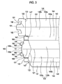
- FIGS. 1 to 3 show a development diagram of a package sheet 100' that is assembled into the package according to embodiments.
- the package sheet 100' may be made of a flexible sheet material by cutting or punching it into the shape of the package sheet 100'.
- Said flexible sheet material may include, but is not limited to, a transparent, translucent or opaque plastic material or other flexible material.
- Diagrams or texts related to a wiper blade may be printed on a surface of the package sheet 100', or a label with the diagrams or texts printed thereon may be adhered to the surface of the package sheet 100'.
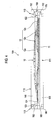
- FIGS. 4 and 5 show the package 100 receiving a wiper blade.
- the package 100 according to an embodiment comprises a receiving portion 110.
- the receiving portion 110 extends in a longitudinal direction of the package 100 and has a receiving cavity 111, into which a wiper blade is put, therein. Further, the receiving portion 110 has a mouth portion 112, which is located at a longitudinal end or a front end, and a bottom portion 113, which is located at a longitudinally opposite end or a rear end.
- the wiper blade may be put into or taken out of the receiving portion 110 through the mouth portion 112.
- the bottom portion 113 may bear the wiper blade received in the receiving portion 110.
- Said wiper blade to be received in the package 100 may include a yoke type wiper blade 10 shown by dashed lines in FIG. 4 or a flat wiper blade 20 shown by dashed lines in FIG. 5 .
- the yoke type wiper blade 10 includes an elongated wiper strip 11 made of a rubber or elastomer material and a frame assembly 12 supporting and holding the wiper strip 11.
- the frame assembly 12 comprises one main yoke 12a and a plurality of sub yokes joined to the main yoke 12a in a bifurcated shape. Clamps 12c provided at distal ends of the sub yokes 12b secure the wiper strip 11.
- the flat wiper blade 20 includes an elongated wiper strip 21 made of a rubber or elastomer material and one elongated flat bar 22 supporting and holding the wiper strip 11.
- the flat bar 22 is curved with a certain curvature.
- the wiper strip 21 is secured to the flat bar 22 as fitted to a longitudinal slot formed in the flat bar 22.
- the package 100 has a plurality of panels that form a body of the package 100.
- said plurality of panels comprise: a first panel 120 located upwardly in the package 100; a second panel 130 located downwardly in the package 100 opposite the first panel 120; and a first side panel 140a and a second side panel 140b located at lateral sides of the package 100 respectively.
- the receiving cavity 111 of the receiving portion 110 is surrounded by the first panel 120, the second panel 130, the first side panel 140a and the second side panel 140b. Since the package 100 is made of a flexible material, adjacent two panels may bend or flex around their common edge 114, 115, 116, 117.
- the first panel 120 has a first bend line 121 that extends in a longitudinal direction between both edges 114, 115 located in a lateral direction.
- the first panel 120 is divided into two sections 120a, 120b relative to the first bend line 121.
- the first panel 120 may bend around the first bend line 121 due to a force acting in the lateral direction. That is, the two sections 120a, 120b of the first panel 120 may be elastically moved toward or away from each other with respect to the first bend line 121.
- the second panel 130 has a second bend line 131 that extends in a longitudinal direction between both edges 116, 117 located in a lateral direction.
- the second panel 130 is divided into two sections 130a, 130b relative to the second bend line 131.
- the second panel 130 may bend around the second bend line 131 due to a force acting in the lateral direction. That is, the two sections 130a, 130b of the second panel 130 may be elastically moved toward or away from each other with respect to the second bend line 131.
- the first side panel 140a is located between the first panel 120 and the second panel 130. Thus, the first side panel 140a extends along the opposing edges 115, 117 of the first panel 120 and the second panel 130. As shown in FIGS. 1 to 3 , a fold line 143 is formed between the first side panel 140a and the first panel 120, and a fold line 144 is formed between the first side panel 140a and the second panel 130.
- the second side panel 140b extends parallel to the first panel 120 along the edge 114 of the first panel 120.
- a fold line 145 is formed between the second side panel 140b and the first panel 120.
- a bonding flap 141 is integrally formed to the opposite edge of the second side panel 140b in a longitudinal direction. As shown in FIGS.
- a fold line 146 is formed between the second side panel 140b and the bonding flap 141.
- the bonding flap 141 may be inwardly folded.
- An outer surface of the bonding flap 141 and an inner surface of the second panel 130 are bonded together by a bonding means, thus forming the body of the package 100 and defining the receiving cavity 111.
- Said bonding means may include a double-sided adhesive tape, a bonding agent, thermal fusion bonding, ultrasonic bonding, etc.
- the first side panel 140a and the second side panel 140b have an extension flap 142 at either longitudinal end.
- the extension flap 142 is integrally formed to the first side panel 140a or the second side panel 140b via a fold line 147 and may be folded toward the inside of the receiving portion 110.
- the extension flap 142 is situated more inward than a lid flap and a bottom flap, which are described below.
- the first panel 120 When assembling the package sheet 100' into the package 100, the first panel 120 is folded such that the first bend line 121 protrudes upward, while the second panel 130 is folded such that the second bend line 131 protrudes downward.
- the receiving portion 110 which has the receiving cavity 111 defined by the two sections 120a, 120b of the first panel 120, the two sections 130a, 130b of the second panel 130, the first side panel 140a and the second side panel 140b, has a hexagonal cross-section. In the cross-sectional shape of the receiving portion 110, the first bend line 121 is located at a top vertex of the hexagon, while the second bend line 131 is located at a bottom vertex of the hexagon.
- the package 100 includes a lid flap 150 that is disposed at the mouth portion 112 of the receiving portion 110 and forms the mouth portion 112.
- the hexagonal lid flap 150 is integrally formed to the longitudinal end or front end of the first panel 120 via a first hinge line 122.
- the lid flap 150 may be pivoted toward the inside or outside of the first panel 120 around the first hinge line 122, i.e., between an open position where the receiving portion 110 is opened and a closed position where the receiving portion 110 is closed.
- the first bend line 121 extends up to a free end 151 of the lid flap 150 across the first hinge line 122.
- the lid flap 150 has two halves 150a, 150b that are divided by the first bend line 121. The two halves 150a, 150b may be moved toward or away from each other with respect to the first bend line 121. That is, the lid flap 150 may be folded around the first bend line 121.
- the first hinge line 122 intersects the first bend line 121 between the edges 114, 115 of the first panel 120 (or between the common edges of the first panel 120 and the first and second side panels 140a, 140b). Further, the first hinge line 122 intersects the first bend line 121 at an acute angle in an inward direction of the first panel 120. That is, the first hinge line 122 is convex toward the inside of the first panel 120 in a V-shape. Since the first hinge line 122 extends at an acute angle in the inward direction, when a lateral force is applied to the first panel 120 and the first panel 120 is bent as protruding upward, the lid flap 150 can be pivoted toward the inside of the first panel 120, i.e., toward the inside of the receiving portion 110.
- the lid flap 150 is foldable around the first bend line 121, the lid flap 150 can be pivoted toward the inside of the receiving portion 110 while its two sections 150a, 150b approach each other. Through the aforementioned pivoting and folding actions, the lid flap 150 opens the mouth portion 112 of the receiving portion 112.
- the first hinge line 122 extends in the shape of a straight line.
- the first hinge line 122 may extend in the shape of a curved line.
- the package 100 includes a first engagement flap 170 for maintaining the lid flap 150 to the position where the receiving portion 110 is closed.
- the first engagement flap 170 is integrally formed to the longitudinal end or front end of the second panel 130 via a fold line 132.
- the fold line 132 of the first engagement panel 170 is located more outwardly than the first hinge line 122 of the lid flap 150.
- the first engagement flap 170 is folded toward the first panel 120, i.e., toward the inside of the receiving portion 110.
- the second bend line 131 of the second panel 130 extends up to a free end 171 of the first engagement flap 170 across the fold line 132.
- the first engagement flap 170 is foldable around the second bend line 131. As shown in FIGS.
- the free end 171 of the first engagement flap 170 is formed in a V shape that is convex toward the outside of the package 100.
- the free end 171 of the first engagement flap 170 has a shape corresponding to the shape of the free end 151 of the lid flap 150.
- a hanging portion 190 for use in hanging the package 100 on a display shelf or a wall surface for displaying the package 100 is provided in the package 100.
- the hanging portion 190 includes a hanging hole 173, which is perforated in the first engagement flap 170, and a hanging hole 134, which is perforated in the second panel 130.
- the hanging hole 173 and the hanging hole 134 are aligned with each other.
- the package 100 may be vertically hung by a peg, which is provided on a display shelf or a wall surface and passes through the hanging holes 134, 173.
- the hanging holes 134, 173 may have various shapes such as a circle, oval, rectangle, diamond, etc.
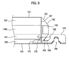
- the lid flap 150 engages the free end 171 of the first engagement flap 170 at its free end 151, thereby closing the mouth portion 112 of the receiving portion 110.
- FIGS. 8 to 10 show the mouth portion 112 of the receiving portion 110 in detail. The engagement between the lid flap 150 and the first engagement flap 170 will be described with reference to FIGS. 1 to 10 .
- the lid flap 150 In the closed position of the receiving portion 110, the free end 151 of the lid flap 150 engages the free end 171 of the first engagement flap 170, allowing the lid flap 150 to be maintained in the closed position.
- the lid flap 150 has a pair of engagement tabs 152, which engage the free end 171 of the first engagement flap 170, at the free end 151.
- the engagement tab 152 extends from the free end 151 of the lid flap 150 and is integrally formed to the free end 151 of the lid flap 150 via a fold line 155.
- the engagement tab 152 has a rectangular shape.
- the engagement tab 152 may have a semi-circular, semi-oval or polygonal shape.
- the engagement tab 152 of the lid flap 150 intervenes between the free end 171 of the first engagement flap 170 and the inner surface of the second panel 130, thereby engaging the free end 171.
- a fixed end 153 of the engagement tab 152 engages the free end 171 of the first engagement flap 170 and a body 154 of the engagement tab 152 intervenes between the first engagement flap 170 and the second panel 130 ( see FIG. 9 ).
- a pair of engagement notches 172 are provided at the free end 171 of the first engagement flap 170.
- the fixed end 153 of the engagement tab 152 is fitted to the engagement notch 172 along the engagement notch 172.
- the fixed end 153 of the engagement tab 152 is fitted to the engagement notch 172 and the body 154 of the engagement tab 152 intervenes between the second panel 130 and the first engagement flap 170.
- the free end 151 of the lid flap 150 is situated more outwardly than the free end 171 of the first engagement flap 170.
- one end of the wiper blade 10, 20, which is received in the receiving portion 110 may contact the lid flap 150 and then apply a force to the lid flap 150 in a direction perpendicular to the lid flap 150. Then, the lid flap 150 may be pivoted toward the outside of the package 100 while pushing the first engagement flap 170 outward. However, a portion of the first engagement flap 170, which is between the free end 151 of the lid flap 150 and the free end 171 of the first engagement flap 170, is situated more inwardly than the free end 151 of the lid flap 150. Thus, the lid flap 150 cannot be pivoted outwardly and is maintained in the closed position.
- FIG. 10 illustrates the opening operation of the lid flap 150.
- the lid flap 150 is pivoted from the first engagement flap 170 to the open position.
- the first panel 120 is bent in an upwardly convex manner, thereby causing the pivoting movement of the lid flap 120.
- the force applied to the first panel in the lateral direction causes the first panel 120 to be bent in an upwardly convex manner.
- the lid flap 150 opens the receiving portion 110 while being folded around the first bend line 121 and being pivoted with respect to the first hinge line 122.
- the aforementioned lateral force is produced by pressing the first and second side panels 140a, 140b in the vicinity of the mouth portion 112 of the receiving portion 110 toward the receiving portion 110.
- the first and second side panels 140a, 140b are pressed toward the inside of the package 100 (i.e., toward the receiving portion 110) in the vicinity of the mouth portion 112. Then, the first panel 120 is bent in an upwardly convex manner around the first bend line 121. In this case, the second panel 130 may also be bent in a downwardly convex manner around the second bend line 131.
- the lid flap 150 is pivoted from the closed position of the receiving portion 110 to the open position, i.e., from the first engagement flap 170 toward the inside of the receiving portion 110, thereby opening the mouth portion 112 of the receiving portion 110.
- the lid flap 150 To pivot the lid flap 150 from the open position of the receiving portion 110 from the closed position, the first and second side panels 140a, 140b are released from the pressure applied thereto. Then, the package 100, which has constricted in the lateral direction, reverts to its original condition. At that point, the first panel 120 is bent in a direction reverse to that at which the first and second side panels are pressed. In addition to the first panel 120 being bent in the reverse direction, the lid flap 150 is pivoted to the closed position of the receiving portion 110 while the engagement tab 152 is inserted in between the first engagement flap 170 and the second panel 130.
- the package 100 includes a bottom flap 160, which is disposed in the bottom portion 113 of the receiving portion and forms the bottom portion 113. Further, the package 100 includes a second engagement flap 180 for fixing the bottom flap 160.
- the bottom flap 160 has the same configuration as the lid flap 150 and the second engagement flap 180 has the same configuration as the first engagement flap 170.
- the bottom flap 160 is integrally formed to the longitudinally opposite end or the rear end of the first panel 120 via a second hinge line 123.
- the first bend line 121 extends up to a free end 161 of the bottom flap 160 across the second hinge line 123.
- the bottom flap 160 is foldable around the first bend line 121 and is pivotable with respect to the second hinge line 123 toward the inside of the receiving portion 110.
- the bottom flap 160 Similar to the lid flap 150, the bottom flap 160 has a hexagonal shape.
- the second hinge line 123 intersects the first bend line 121 between the edges 114, 115 of the first panel 120 (or between the common edges of the first panel 120 and the first and second side panels 140a, 140b). Further, the second hinge line 123 intersects the first bend line 121 at an acute angle in an inward direction of the first panel 120. That is, the second hinge line 123 is convex toward the inside of the first panel 120 in a V-shape.
- the second hinge line 123 extends in the shape of a straight line.
- the second hinge line 123 may extend in the shape of a curved line.
- the second engagement flap 180 is integrally formed to the longitudinally opposite end or rear end of the second panel 130 via a fold line 133.
- the second engagement flap 180 is folded toward the first panel 120, i.e., toward the inside of the receiving portion 110.
- the second bend line 131 of the second panel 130 extends up to a free end 181 of the second engagement flap 180 across the fold line 133.
- the free end 181 of the second engagement flap 180 is formed in a V-shape that is convex toward the outside of the package 100.
- the free end 181 of the second engagement flap 180 has a shape corresponding to the shape of the free end 161 of the bottom flap 160.
- the bottom flap 160 is fixed through engagement between its free end 161 and the free end 181 of the second engagement flap 180.
- the bottom flap 160 has, at its free end 161, a pair of engagement tabs 162 that engages the free end 181of the second engagement flap 180.
- the engagement tab 162 extends from the free end 161 of the bottom flap 160.
- the engagement tab 162 is folded in a direction opposite to the folded direction of the bottom flap 160 around a fold line 165 located at a fixed end 163 of the engagement tab 162.
- a pair of engagement notches 182 are provided at the free end 181 of the second engagement flap 180.
- the fixed end 163 of the engagement tab 162 is fitted to the engagement notch 182 and a body 164 of the engagement tab 162 intervenes between the second engagement flap 180 and the second panel 130.
- the free end 161 of the bottom flap 160 is situated more outwardly than the free end 181 of the second engagement flap 180.
- the bottom flap 160 cannot be pivoted outwardly while pushing the second engagement flap 180 outward, thereby reliably preventing the wiper blade 10, 20 from falling out of the package 100 through the bottom portion 113.
- the first panel 120 may be bent by applying a force to the first and second side panels 140a, 140b at the vicinity of the mouth portion 112. However, the bending of the first panel 120 does not extend down to the bottom portion 113. Further, the lid flap 150 is engaged with the first engagement flap 170 in the closed position of the receiving portion 110 and is therefore maintained in the closed position unless the lateral force is applied to the first panel 120.
- the halves 150a, 150b of the lid flap 150 are folded in an inwardly convex manner around the first bend line 121 and the first bend line 121 within the lid flap 150 is situated approximately perpendicular to the first panel 120 and the second panel 130.
- the first bend line 121 and the halves 150a, 150b folded around the first bend line 121 resist the perpendicular load. This allows the mouth portion 112 of the receiving portion 110 to have high structural rigidity.
- the halves 160a, 160b of the bottom flap 160 are folded in an inwardly convex manner.
- the first bend line 121 within the bottom flap 160 and the halves 160a, 160b of the bottom flap 160 allow the bottom portion 113 of the receiving portion 110 to have high structural rigidity.
- the mouth portion 112 and the bottom portion 113 of the package 100 have a high structural rigidity.
- a large number of the packages 100 may be piled together in a box 30 for packaging or transportation.
- an individual package 100 has a resistance against the perpendicular load.
- the package 100 is not deformed or crushed and the wiper blade 10, 20 therein is prevented from being damaged.
- the package 100 has a hexagonal cross-section, the packages can be closely retained in the box 30 without shaking during transportation.
- the bend lines, the hinge lines and the fold lines described above may comprise indentations, scores, creases, perforations and the like formed in the package sheet 100'.
- the aforementioned lines may be formed by squeezing the package sheet 100' in its thickness direction, for example, by stamping or indenting the package sheet 100'. Further, the aforementioned lines may be formed when manufacturing the package sheet 100' from a raw sheet material, or after cutting or punching the package sheet 100' from a raw sheet material.
- the package sheet 100' shown in FIG. 1 is folded and the receiving portion 110 of the package 100 is formed.
- the second panel 130, the second side panel 140b, the first panel 120 and the first side panel 140a are folded around the common edges 114, 115, 116, 117, and the bonding flap 141 of the second side panel 140b and the lateral edge of the second panel 130 associated with the bonding flap 141 are bonded together by the aforementioned bonding means.
- the receiving portion 110 with the mouth portion 112 opened is formed. While the panels are folded as described above, the first panel 120 and the second panel 130 may be folded such that the first bend line 121 and the second bend line 131 protrude upwardly and downwardly, respectively.
- the first panel 120 and the second panel 130 may be folded such that the first bend line 121 and the second bend line 131 protrude upwardly and downwardly, respectively. If the bonding flap 141 is bonded and the first panel 120 and the second panel 130 are folded, the receiving portion 110 including the receiving cavity 111 having a hexagonal cross-section is formed.
- the first engagement flap 170 is folded toward the first panel 120, i.e., toward the inside of the receiving portion 110. Further, the extension flaps 142 of the first and second side panel 140a, 140b are folded toward the inside of the receiving portion 110.
- the lid flap 150 is pivoted toward the inside of the receiving portion 110 to close the mouth portion 112 of the receiving portion 110. Subsequently, the free end 151 of the lid flap 150 is brought into engagement with the free end 171 of the first engagement flap 170. If the first and second side panels 140a, 140b are pressed toward the receiving portion 110 at the vicinity of the mouth portion 112, then the first panel 120 and the second panel 130 are bent in upwardly convex and downwardly convex manners, respectively, and the lid flap 150 is further pivoted toward the inside of the receiving portion 110 accordingly. As the lid flap 150 is pivoted, the engagement tab 152 of the lid flap 150 faces toward the engagement notch 172 of the first engagement flap 170.
- the lid flap 150 is pivoted toward the outside of the receiving portion 110 and the engagement tab 152 is fitted in between the first engagement flap 170 and the second panel 130. As a result, the lid flap 150 is maintained in the closed position of the receiving portion 110 and the mouth portion 112 is closed.
- the assembly of the bottom portion 113 of the receiving portion 110 may be performed in a manner similar to the above-described exemplary assembly of the mouth portion 112.
- the first and second side panels 140a, 140b may be pressed toward the receiving portion 110 at the vicinity of the bottom portion 113.
- the bottom flap 160 is pivoted from the second engagement flap 180 toward the inside of the receiving portion 110 and the engagement tab 162 of the bottom flap 160 is separated from the second engagement flap 180, thereby opening the bottom portion 113.
- FIG. 16 shows a package according to another embodiment.
- a second panel 230 consists of a unitary panel and does not have a bend line extending in a longitudinal direction.
- the second panel 230 does not have two sections that are movable toward or away from each other around a bend line.
- the receiving portion of the package 200 has an approximately pentagonal cross-section, and the lid flap and the bottom flap have a pentagonal shape accordingly.
- the unitary package sheet 100' is provided with all of the first panel 120, the second panel 130, 230 and the first and second side panels 140a, 140b.
- each of the panels may be made individually and associated panels may be bonded together along their corresponding edges.
- the second panel 130, 230 has the hanging hole 134 and the first engagement flap 170 has the hanging hole 173.
- Another embodiment may include the second engagement flap 180 with the hanging hole and the second panel 130, 230 with the hanging hole corresponding to the hanging hole of the second engagement flap 180.
- the package in this example may be used in such a manner that the bottom flap 160 serves as the mouth portion of the receiving portion, since the bottom flap 160 is openable and closable like the lid flap 150.
- the engagement flaps for fixing the lid flap 150 and the bottom flap 160 are integrated with the longitudinal ends of the second panel 130, 230. In other embodiments, the engagement flaps may be made individually and attached to the longitudinal ends of the second panel 130, 230.
- the package 100, 200 according to the embodiments disclosed herein has the mouth portion 112 that is openable through pressure in the lateral direction.
- the user or consumer can open the mouth portion 112 of the package by pressing the mouth portion 112 in the lateral direction.
- the package 100, 200 according to the embodiments has the bottom portion 113 which is prevented from being pivoted through the engagement configuration.
- the wiper blade 10, 20 received in the package cannot fall out of the package.
- the package 100, 200 according to the embodiments has the mouth portion 112 and the bottom portion 113 which resist a perpendicular load.
- the perpendicular load is applied to the package during the handling or transporting of the package, the package does not easily deform, thereby preventing damage to the wiper blade.
Description
- The present invention relates to a wiper blade package for receiving a wiper blade therein.
- A wiper blade for use in wiping a windshield of a motor vehicle has a wiper strip. The wiper strip is worn due to contact with the surface of a windshield. When the service life of a wiper strip comes to an end, the wiper blade is replaced with a new one. New wiper blades may be purchased at car accessory shops. Typically, wiper blades are displayed in the car accessory shops as contained in packages.
- The package for receiving a wiper blade must be designed so as to appropriately receive a long wiper blade. Further, the package must be designed such that the wiper strip of a wiper blade and parts for securing the wiper strip is protected during handling or transportation. International Patent Application Publication No.
WO 2008/036964 discloses a package for receiving a flat wiper blade. - When a consumer purchases a wiper blade, the consumer takes a wiper blade out of the package and then inspects the wiper blade and its wiper strip. Then, after inspection, the consumer puts the wiper blade into the package again. If the mouth portion of the package cannot be easily opened or closed, it could be troublesome or inconvenient for the consumer when the wiper blade is taken out and put back into the package. Further, the package must be structurally rigid in order to protect the wiper blade received therein and the parts of the wiper blade. When the package falls to the ground, the wiper blade received therein can come out of the package, and when many packages are piled together within a box, the package can become compressed. This may cause damage of the wiper blade received in the package. Another package is known from
US 4 388 993 . - However, conventional wiper blade packages have limits regarding easy opening of the mouth portion of the package through simple manipulation. Further, conventional wiper blade packages are unsatisfactory in terms of structural rigidity.
- The present invention is directed to solving the aforementioned problems. The present invention provides a wiper blade package wherein a mouth portion can be opened with simple manipulation. Further, the present invention provides a wiper blade package wherein a mouth portion and a bottom portion are constructed with a strong structure. Further, the present invention provides a wiper blade package that can be closely piled within a box.
- According to various aspects, there are provided numerous embodiments of a wiper blade package wherein a mouth portion is openable by being pressed in a lateral direction.
- According to the invention a wiper blade package includes a receiving portion having a receiving cavity that is surrounded by a first panel, a second panel, a first side panel and a second side panel. The first panel is bendable around a first bend line that extends in a longitudinal direction between both lateral edges. The first panel has a lid flap at a longitudinal end. The lid flap is foldable around the first bend line and is pivotable around a first hinge line which intersects the first bend line at an acute angle in an inward direction. The second panel is opposed to the first panel and has a first engagement flap folded toward the first panel at a longitudinal end. The first side panel extends along opposing edges of the first panel and the second panel. The second side panel extends along edges opposed to the opposing edges of the first panel and the second panel. The lid flap engages a free end of the first engagement flap at its free end and thereby closes the receiving portion. Further, by pressing the first and second side panels toward the receiving portion, the lid flap is pivoted from the first engagement flap and thereby opens the receiving portion.
- According to the present invention, the lid flap has, at its free end, at least one engagement tab which engages the free end of the first engagement flap. In a closed position where the lid flap closes the receiving portion, the engagement tab intervenes between the first engagement flap and the second panel. In such an embodiment, the first engagement flap has an engagement notch, to which a fixed end of the engagement tab is fitted, at its free end. Further, the free end of the lid flap may be situated more outwardly than the free end of the first engagement flap in the closed position where the lid flap closes the receiving portion. Further, the lid flap has a pair of halves divided by the first bend line. The pair of the halves are folded around the first bend line in the closed position where the lid flap closes the receiving portion.
- In an embodiment of the present invention, the first panel has a bottom flap at a longitudinally opposite end. The bottom flap is foldable around the first bend line and is pivotable around a second hinge line intersecting the first bend line at an acute angle in an inward direction. The second panel has a second engagement flap folded toward the first panel at a longitudinally opposite end. The bottom flap has at least one engagement tab, which is inserted in between the second engagement flap and the second panel, at a free end thereof. In such an embodiment, the second engagement flap may have an engagement notch, to which a fixed end of the engagement tab of the bottom flap is fitted, at the free end thereof. Further, when the bottom flap is in engagement with the second engagement flap, the free end of the bottom flap may be situated more outwardly than the free end of the second engagement flap. Further, the bottom flap has a pair of halves divided by the first bend line. When the bottom flap is in engagement with the second engagement flap, the pair of the halves of the bottom flap are folded around the first bend line.
- In an embodiment of the present invention, the second panel is bendable around a second bend line extending in a longitudinal direction between both lateral edges.
- In an embodiment of the present invention, the lid flap has a shape of a pentagon or hexagon.
- In an embodiment of the present invention, the wiper blade package further includes hanging holes perforated through the second panel and the first engagement flap.
- Arrangements and embodiments may be described in detail with reference to the following drawings in which like reference numerals refer to like elements or components, wherein:
-
FIG. 1 shows a development diagram of a package sheet that is assembled into a wiper blade package according to an embodiment; -
FIG. 2 shows an enlarged diagram of the right side of the development diagram shown inFIG. 1 ; -
FIG. 3 shows an enlarged diagram of the left side of the development diagram shown inFIG. 1 ; -
FIG. 4 is a top view of a wiper blade package according to an embodiment and shows an example of a wiper blade to be received in the package in dashed lines; -
FIG. 5 is a top view of a wiper blade package according to an embodiment and shows another example of a wiper blade to be received in the package in dashed lines; -
FIG. 6 is a side view of a wiper blade package according to an embodiment; -
FIG. 7 shows a cross-section of a wiper blade package according to an embodiment; -
FIG. 8 is a perspective view showing a mouth portion of the wiper blade package shown inFIGS. 4 and5 ; -
FIG. 9 is a sectional view taken along the line IX-IX ofFIG. 8 ; -
FIG. 10 illustrates opening of a mouth portion of a wiper blade package; -
FIG. 11 is a perspective view showing a bottom portion of the wiper blade package shown inFIGS. 4 and5 ; -
FIG. 12 is a schematic diagram illustrating an embodiment where wiper blade packages are piled together; -
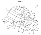
FIG. 13 is a perspective view showing the mouth portion of a wiper blade package according to an embodiment, wherein the mouth portion is not yet assembled; -
FIG. 14 is a perspective view showing the mouth portion of a wiper blade package according to an embodiment, wherein the mouth portion is partially assembled; -
FIG. 15 is a perspective view showing the mouth portion of a wiper blade package according to an embodiment, wherein the mouth portion is assembled; and -
FIG. 16 shows a wiper blade package according to another embodiment. - Detailed descriptions will be made as to embodiments of a wiper blade package with reference to the accompanying drawings.
- The directional term "upper," "upward" or the like as used herein is based on a direction in which a lid flap is located relative to a second panel in a wiper blade package shown in the accompanying drawings, while the directional term "Iower," "downward" or the like refers to a direction opposite to the upper or upward direction. Further, as used herein, the directional term "front," "frontward" or the like is based on a direction in which a hanging hole is located relative to a bottom flap in the wiper blade package shown in the accompanying drawings, while the directional term "rear," "rearward" or the like refers to a direction opposite to the front or frontward direction. The wiper blade package shown in the accompanying drawings may be otherwise oriented and the aforementioned directional terms may be interpreted accordingly. Further, as used herein, the directional term "inward", "inner" or the like means a direction directed toward a center of the wiper blade package, while the directional term "outward," "outer" or the like means a direction opposite to the inward or inner direction.
- The term "fold line" as used herein means a line that is located between two parts adjacent to one another via such a line when one part of said two parts is foldable toward the other part or said two parts are foldable toward each other. Further, as used herein, the term "hinge line" means a line that is located between two parts adjacent to one another via such a line when one part of said two parts is pivotable relative to the other part of said two parts. Further, as used herein, the term "bent," "bending" or the like means that two sections divided by a line in a panel or flap of the wiper blade package are elastically movable toward or away from each other and the line located between said two sections are referred to as "a bend line." Further, said fold line may be understood as including said hinge line and said bend line.
- The wiper blade package (hereinafter, simply referred to as "package") according to embodiments is configured to receive a wiper blade therein. Exemplary articles to be received by the package are not limited to a wiper blade and may include other elongated articles.
- The package according to embodiments has a receiving portion that extends in a longitudinal direction of the package and receives the wiper blade. The receiving portion has a receiving cavity which is surrounded by a plurality of panels forming a body of the package. In the plurality of panels, two adjacent panels may be moved toward or away from each other around their common edge. In one embodiment, said plurality of panels comprise: a first panel located upwardly in the package; a second panel located downwardly in the package opposite the first panel; and two side panels extending along opposing lateral edges of the first and second panels, respectively. The first and second panels have a bend line that extends in a longitudinal direction between the lateral edges. In this embodiment, the cross-sectional shape of the receiving portion becomes a hexagon. In another embodiment, the second panel consists of a unitary panel without the bend line. In this embodiment, the cross-sectional shape of the receiving portion becomes a pentagon.
- In the package according to embodiments, a pentagonal or hexagonal lid flap, which is pivotable to open or close the receiving portion, is disposed at a mouth portion of the receiving portion. In one embodiment, the lid flap comprises two halves that are foldable around the bend line. The lid flap is integrally formed to a longitudinal end of the first panel via a hinge line. The lid flap is pivotable between a closed position where the receiving portion is closed and an open position where the receiving portion is opened.
- In the package according to embodiments, the hinge line of the lid flap intersects the bend line at an acute angle in an inward direction. If a force or pressure is applied to the first panel in a lateral direction, then the lid flap is pivoted toward the inside of the receiving portion due to the angle of the hinge line relative to the bend line. Further, since the lid flap is foldable around the bend line of the first panel, the lid flap is pivoted toward the inside of the receiving portion while the two halves divided by the bend line are folded convexly toward the inside of the receiving portion. Through the aforementioned folding action and pivoting action, the lid flap opens the receiving portion. If the force or pressure is removed, the lid flap reverts to the closed position due to the restoration force of the first panel.
- The package according to embodiments has a first engagement flap for maintaining the lid flap in the closed position. In one embodiment, the first engagement flap is integrally formed to a longitudinal end of the second panel and is folded toward the first panel, i.e., toward the inside of the receiving portion. Further, the lid flap is maintained in the closed position as engaged with a free end of the first engagement flap at its free end. In one embodiment, the lid flap has, at its free end, an engagement tab intervening between the second panel and the first engagement flap in the closed position. Further, to ensure the fixation of the lid flap in the closed position, an engagement notch is provided at the free end of the first engagement flap and a fixed end of the engagement tab of the lid flap is fitted to the engagement notch in the closed position. Further, in the closed position, the free end of the first engagement flap is more inward than the free end of the lid flap. Thus, although a force pushing or pivoting the lid flap out of the closed position is applied to the lid flap, a portion of the first engagement flap, which is more inward than the free end of the lid flap, allows the lid flap to be maintained in the closed position.
- In the package according to embodiments, the bottom portion of the receiving portion is constructed using the aforementioned engagement configuration between the lid flap and the first engagement flap. In one embodiment, the first panel has a bottom flap at its longitudinally opposite end and the second panel has a second engagement flap at its longitudinally opposite end. The bottom flap has the same configuration as the lid flap and the second engagement flap has the same configuration as the first engagement flap. The bottom flap engages a free end of the section engagement flap at its free end, thereby forming the bottom portion. The bottom flap is pivotable between an open position where the bottom portion is opened and a closed position where the bottom portion is closed. The free end of the second engagement flap is more inward than the free end of the bottom flap. Thus, although a force perpendicular to the bottom flap is applied to the bottom flap engaged with the section engagement flap, the bottom flap cannot be pivoted outward due to the engagement with the second engagement flap.
- The package according to embodiments is capable of resisting a perpendicular load at the mouth portion and the bottom portion of the receiving portion. In the lid flap situated in the closed position and the bottom flap forming the bottom portion, the two halves divided by the bend line of the first panel are folded around the bend line and the bend line between the two halves are situated perpendicularly to the first panel or the second panel. Accordingly, the bend line and the two folded halves in the lid flap or the bottom flap can resist the perpendicular load.
-
FIGS. 1 to 3 show a development diagram of a package sheet 100' that is assembled into the package according to embodiments. The package sheet 100' may be made of a flexible sheet material by cutting or punching it into the shape of the package sheet 100'. Said flexible sheet material may include, but is not limited to, a transparent, translucent or opaque plastic material or other flexible material. Diagrams or texts related to a wiper blade may be printed on a surface of the package sheet 100', or a label with the diagrams or texts printed thereon may be adhered to the surface of the package sheet 100'. -
FIGS. 4 and5 show thepackage 100 receiving a wiper blade. Referring toFIGS. 4 and5 , thepackage 100 according to an embodiment comprises a receivingportion 110. The receivingportion 110 extends in a longitudinal direction of thepackage 100 and has a receivingcavity 111, into which a wiper blade is put, therein. Further, the receivingportion 110 has amouth portion 112, which is located at a longitudinal end or a front end, and abottom portion 113, which is located at a longitudinally opposite end or a rear end. The wiper blade may be put into or taken out of the receivingportion 110 through themouth portion 112. Thebottom portion 113 may bear the wiper blade received in the receivingportion 110. - Said wiper blade to be received in the
package 100 may include a yoketype wiper blade 10 shown by dashed lines inFIG. 4 or aflat wiper blade 20 shown by dashed lines inFIG. 5 . - The yoke
type wiper blade 10 includes anelongated wiper strip 11 made of a rubber or elastomer material and aframe assembly 12 supporting and holding thewiper strip 11. Theframe assembly 12 comprises onemain yoke 12a and a plurality of sub yokes joined to themain yoke 12a in a bifurcated shape.Clamps 12c provided at distal ends of the sub yokes 12b secure thewiper strip 11. - The
flat wiper blade 20 includes anelongated wiper strip 21 made of a rubber or elastomer material and one elongatedflat bar 22 supporting and holding thewiper strip 11. Theflat bar 22 is curved with a certain curvature. Thewiper strip 21 is secured to theflat bar 22 as fitted to a longitudinal slot formed in theflat bar 22. - Referring to
FIGS. 1 to 7 , thepackage 100 has a plurality of panels that form a body of thepackage 100. In this embodiment, said plurality of panels comprise: afirst panel 120 located upwardly in thepackage 100; asecond panel 130 located downwardly in thepackage 100 opposite thefirst panel 120; and afirst side panel 140a and asecond side panel 140b located at lateral sides of thepackage 100 respectively. The receivingcavity 111 of the receivingportion 110 is surrounded by thefirst panel 120, thesecond panel 130, thefirst side panel 140a and thesecond side panel 140b. Since thepackage 100 is made of a flexible material, adjacent two panels may bend or flex around theircommon edge - The
first panel 120 has afirst bend line 121 that extends in a longitudinal direction between bothedges first panel 120 is divided into twosections first bend line 121. Thefirst panel 120 may bend around thefirst bend line 121 due to a force acting in the lateral direction. That is, the twosections first panel 120 may be elastically moved toward or away from each other with respect to thefirst bend line 121. Thesecond panel 130 has asecond bend line 131 that extends in a longitudinal direction between bothedges second panel 130 is divided into twosections second bend line 131. Thesecond panel 130 may bend around thesecond bend line 131 due to a force acting in the lateral direction. That is, the twosections second panel 130 may be elastically moved toward or away from each other with respect to thesecond bend line 131. - The
first side panel 140a is located between thefirst panel 120 and thesecond panel 130. Thus, thefirst side panel 140a extends along the opposingedges first panel 120 and thesecond panel 130. As shown inFIGS. 1 to 3 , afold line 143 is formed between thefirst side panel 140a and thefirst panel 120, and afold line 144 is formed between thefirst side panel 140a and thesecond panel 130. Thesecond side panel 140b extends parallel to thefirst panel 120 along theedge 114 of thefirst panel 120. Afold line 145 is formed between thesecond side panel 140b and thefirst panel 120. Abonding flap 141 is integrally formed to the opposite edge of thesecond side panel 140b in a longitudinal direction. As shown inFIGS. 1 to 3 , afold line 146 is formed between thesecond side panel 140b and thebonding flap 141. Thebonding flap 141 may be inwardly folded. An outer surface of thebonding flap 141 and an inner surface of thesecond panel 130 are bonded together by a bonding means, thus forming the body of thepackage 100 and defining the receivingcavity 111. Said bonding means may include a double-sided adhesive tape, a bonding agent, thermal fusion bonding, ultrasonic bonding, etc. When the outer surface of thebonding flap 141 and the inner surface of thesecond panel 130 are bonded together, thefold line 146 of thebonding flap 141 is aligned to theedge 116 of thesecond panel 130. Therefore, in the assembledpackage 100, thesecond side panel 140b extends along theedges edges second panels - The
first side panel 140a and thesecond side panel 140b have anextension flap 142 at either longitudinal end. Theextension flap 142 is integrally formed to thefirst side panel 140a or thesecond side panel 140b via afold line 147 and may be folded toward the inside of the receivingportion 110. In the assembledpackage 100, theextension flap 142 is situated more inward than a lid flap and a bottom flap, which are described below. - When assembling the package sheet 100' into the
package 100, thefirst panel 120 is folded such that thefirst bend line 121 protrudes upward, while thesecond panel 130 is folded such that thesecond bend line 131 protrudes downward. As shown inFIG. 7 , the receivingportion 110, which has the receivingcavity 111 defined by the twosections first panel 120, the twosections second panel 130, thefirst side panel 140a and thesecond side panel 140b, has a hexagonal cross-section. In the cross-sectional shape of the receivingportion 110, thefirst bend line 121 is located at a top vertex of the hexagon, while thesecond bend line 131 is located at a bottom vertex of the hexagon. - The
package 100 includes alid flap 150 that is disposed at themouth portion 112 of the receivingportion 110 and forms themouth portion 112. In this embodiment, thehexagonal lid flap 150 is integrally formed to the longitudinal end or front end of thefirst panel 120 via afirst hinge line 122. Thus, thelid flap 150 may be pivoted toward the inside or outside of thefirst panel 120 around thefirst hinge line 122, i.e., between an open position where the receivingportion 110 is opened and a closed position where the receivingportion 110 is closed. Further, thefirst bend line 121 extends up to afree end 151 of thelid flap 150 across thefirst hinge line 122. Thus, thelid flap 150 has twohalves first bend line 121. The twohalves first bend line 121. That is, thelid flap 150 may be folded around thefirst bend line 121. - The
first hinge line 122 intersects thefirst bend line 121 between theedges first panel 120 and the first andsecond side panels first hinge line 122 intersects thefirst bend line 121 at an acute angle in an inward direction of thefirst panel 120. That is, thefirst hinge line 122 is convex toward the inside of thefirst panel 120 in a V-shape. Since thefirst hinge line 122 extends at an acute angle in the inward direction, when a lateral force is applied to thefirst panel 120 and thefirst panel 120 is bent as protruding upward, thelid flap 150 can be pivoted toward the inside of thefirst panel 120, i.e., toward the inside of the receivingportion 110. Further, since thelid flap 150 is foldable around thefirst bend line 121, thelid flap 150 can be pivoted toward the inside of the receivingportion 110 while its twosections lid flap 150 opens themouth portion 112 of the receivingportion 112. In the illustrated embodiment, thefirst hinge line 122 extends in the shape of a straight line. Alternatively, thefirst hinge line 122 may extend in the shape of a curved line. - The
package 100 includes afirst engagement flap 170 for maintaining thelid flap 150 to the position where the receivingportion 110 is closed. Thefirst engagement flap 170 is integrally formed to the longitudinal end or front end of thesecond panel 130 via afold line 132. Thefold line 132 of thefirst engagement panel 170 is located more outwardly than thefirst hinge line 122 of thelid flap 150. Thefirst engagement flap 170 is folded toward thefirst panel 120, i.e., toward the inside of the receivingportion 110. Thesecond bend line 131 of thesecond panel 130 extends up to afree end 171 of thefirst engagement flap 170 across thefold line 132. Thus, thefirst engagement flap 170 is foldable around thesecond bend line 131. As shown inFIGS. 1 and2 , thefree end 171 of thefirst engagement flap 170 is formed in a V shape that is convex toward the outside of thepackage 100. Thefree end 171 of thefirst engagement flap 170 has a shape corresponding to the shape of thefree end 151 of thelid flap 150. - A hanging
portion 190 for use in hanging thepackage 100 on a display shelf or a wall surface for displaying thepackage 100 is provided in thepackage 100. In this embodiment, the hangingportion 190 includes a hanginghole 173, which is perforated in thefirst engagement flap 170, and a hanginghole 134, which is perforated in thesecond panel 130. When thefirst engagement flap 170 is folded onto thesecond panel 130, the hanginghole 173 and the hanginghole 134 are aligned with each other. Thepackage 100 may be vertically hung by a peg, which is provided on a display shelf or a wall surface and passes through the hangingholes - The
lid flap 150 engages thefree end 171 of thefirst engagement flap 170 at itsfree end 151, thereby closing themouth portion 112 of the receivingportion 110.FIGS. 8 to 10 show themouth portion 112 of the receivingportion 110 in detail. The engagement between thelid flap 150 and thefirst engagement flap 170 will be described with reference toFIGS. 1 to 10 . - In the closed position of the receiving
portion 110, thefree end 151 of thelid flap 150 engages thefree end 171 of thefirst engagement flap 170, allowing thelid flap 150 to be maintained in the closed position. In this embodiment, thelid flap 150 has a pair ofengagement tabs 152, which engage thefree end 171 of thefirst engagement flap 170, at thefree end 151. Theengagement tab 152 extends from thefree end 151 of thelid flap 150 and is integrally formed to thefree end 151 of thelid flap 150 via afold line 155. In the illustrated embodiment, theengagement tab 152 has a rectangular shape. Alternatively, theengagement tab 152 may have a semi-circular, semi-oval or polygonal shape. - In the closed position of the receiving
portion 110, theengagement tab 152 of thelid flap 150 intervenes between thefree end 171 of thefirst engagement flap 170 and the inner surface of thesecond panel 130, thereby engaging thefree end 171. Specifically, afixed end 153 of theengagement tab 152 engages thefree end 171 of thefirst engagement flap 170 and abody 154 of theengagement tab 152 intervenes between thefirst engagement flap 170 and the second panel 130 (seeFIG. 9 ). - Further, to fix the
lid flap 150 in the closed position, a pair ofengagement notches 172 are provided at thefree end 171 of thefirst engagement flap 170. When thelid flap 150 is pivoted from the open position of the receivingportion 110 to the closed position, thefixed end 153 of theengagement tab 152 is fitted to theengagement notch 172 along theengagement notch 172. In the closed position of the receivingportion 110, thefixed end 153 of theengagement tab 152 is fitted to theengagement notch 172 and thebody 154 of theengagement tab 152 intervenes between thesecond panel 130 and thefirst engagement flap 170. Further, thefree end 151 of thelid flap 150 is situated more outwardly than thefree end 171 of thefirst engagement flap 170. When thelid flap 150 is in the closed position, one end of thewiper blade portion 110, may contact thelid flap 150 and then apply a force to thelid flap 150 in a direction perpendicular to thelid flap 150. Then, thelid flap 150 may be pivoted toward the outside of thepackage 100 while pushing thefirst engagement flap 170 outward. However, a portion of thefirst engagement flap 170, which is between thefree end 151 of thelid flap 150 and thefree end 171 of thefirst engagement flap 170, is situated more inwardly than thefree end 151 of thelid flap 150. Thus, thelid flap 150 cannot be pivoted outwardly and is maintained in the closed position. -
FIG. 10 illustrates the opening operation of thelid flap 150. When the receivingportion 110 is opened in order to take thewiper blade package 100, thelid flap 150 is pivoted from thefirst engagement flap 170 to the open position. Thefirst panel 120 is bent in an upwardly convex manner, thereby causing the pivoting movement of thelid flap 120. The force applied to the first panel in the lateral direction causes thefirst panel 120 to be bent in an upwardly convex manner. If thefirst panel 120 is bent, then thelid flap 150 opens the receivingportion 110 while being folded around thefirst bend line 121 and being pivoted with respect to thefirst hinge line 122. The aforementioned lateral force is produced by pressing the first andsecond side panels mouth portion 112 of the receivingportion 110 toward the receivingportion 110. - As shown by arrows F in
FIG. 10 , the first andsecond side panels mouth portion 112. Then, thefirst panel 120 is bent in an upwardly convex manner around thefirst bend line 121. In this case, thesecond panel 130 may also be bent in a downwardly convex manner around thesecond bend line 131. In addition to thefirst panel 120 being bent, thelid flap 150 is pivoted from the closed position of the receivingportion 110 to the open position, i.e., from thefirst engagement flap 170 toward the inside of the receivingportion 110, thereby opening themouth portion 112 of the receivingportion 110. - To pivot the
lid flap 150 from the open position of the receivingportion 110 from the closed position, the first andsecond side panels package 100, which has constricted in the lateral direction, reverts to its original condition. At that point, thefirst panel 120 is bent in a direction reverse to that at which the first and second side panels are pressed. In addition to thefirst panel 120 being bent in the reverse direction, thelid flap 150 is pivoted to the closed position of the receivingportion 110 while theengagement tab 152 is inserted in between thefirst engagement flap 170 and thesecond panel 130. - Referring to
FIGS. 1 to 3 , thepackage 100 includes abottom flap 160, which is disposed in thebottom portion 113 of the receiving portion and forms thebottom portion 113. Further, thepackage 100 includes asecond engagement flap 180 for fixing thebottom flap 160. In this embodiment, thebottom flap 160 has the same configuration as thelid flap 150 and thesecond engagement flap 180 has the same configuration as thefirst engagement flap 170. - The
bottom flap 160 is integrally formed to the longitudinally opposite end or the rear end of thefirst panel 120 via asecond hinge line 123. Thefirst bend line 121 extends up to afree end 161 of thebottom flap 160 across thesecond hinge line 123. Thus, thebottom flap 160 is foldable around thefirst bend line 121 and is pivotable with respect to thesecond hinge line 123 toward the inside of the receivingportion 110. Similar to thelid flap 150, thebottom flap 160 has a hexagonal shape. - The
second hinge line 123 intersects thefirst bend line 121 between theedges first panel 120 and the first andsecond side panels second hinge line 123 intersects thefirst bend line 121 at an acute angle in an inward direction of thefirst panel 120. That is, thesecond hinge line 123 is convex toward the inside of thefirst panel 120 in a V-shape. Thus, when a force in the lateral direction is applied to thefirst panel 120 in the vicinity of thebottom portion 113 of the receivingportion 110 and thefirst panel 120 is bent thereby, thebottom flap 160 may be pivoted toward the inside of the receivingportion 110. In the illustrated embodiment, thesecond hinge line 123 extends in the shape of a straight line. Alternatively, thesecond hinge line 123 may extend in the shape of a curved line. - The
second engagement flap 180 is integrally formed to the longitudinally opposite end or rear end of thesecond panel 130 via afold line 133. Thesecond engagement flap 180 is folded toward thefirst panel 120, i.e., toward the inside of the receivingportion 110. Thesecond bend line 131 of thesecond panel 130 extends up to afree end 181 of thesecond engagement flap 180 across thefold line 133. As shown inFIGS. 1 and3 , thefree end 181 of thesecond engagement flap 180 is formed in a V-shape that is convex toward the outside of thepackage 100. Thefree end 181 of thesecond engagement flap 180 has a shape corresponding to the shape of thefree end 161 of thebottom flap 160. - The
bottom flap 160 is fixed through engagement between itsfree end 161 and thefree end 181 of thesecond engagement flap 180. Thebottom flap 160 has, at itsfree end 161, a pair ofengagement tabs 162 that engages the free end 181of thesecond engagement flap 180. Theengagement tab 162 extends from thefree end 161 of thebottom flap 160. Theengagement tab 162 is folded in a direction opposite to the folded direction of thebottom flap 160 around afold line 165 located at afixed end 163 of theengagement tab 162. - Further, to fix the
bottom flap 160, a pair ofengagement notches 182 are provided at thefree end 181 of thesecond engagement flap 180. Referring toFIG. 11 , when thebottom flap 160 is fixed, thefixed end 163 of theengagement tab 162 is fitted to theengagement notch 182 and abody 164 of theengagement tab 162 intervenes between thesecond engagement flap 180 and thesecond panel 130. Further, thefree end 161 of thebottom flap 160 is situated more outwardly than thefree end 181 of thesecond engagement flap 180. Therefore, even if a force is applied to thebottom flap 160 in a direction perpendicular to thebottom flap 160, thebottom flap 160 cannot be pivoted outwardly while pushing thesecond engagement flap 180 outward, thereby reliably preventing thewiper blade package 100 through thebottom portion 113. - To pivot the
lid flap 150 to the open position, thefirst panel 120 may be bent by applying a force to the first andsecond side panels mouth portion 112. However, the bending of thefirst panel 120 does not extend down to thebottom portion 113. Further, thelid flap 150 is engaged with thefirst engagement flap 170 in the closed position of the receivingportion 110 and is therefore maintained in the closed position unless the lateral force is applied to thefirst panel 120. When thelid flap 150 is in the closed position or at the vicinity of the closed position, thehalves lid flap 150 are folded in an inwardly convex manner around thefirst bend line 121 and thefirst bend line 121 within thelid flap 150 is situated approximately perpendicular to thefirst panel 120 and thesecond panel 130. Thus, when a force is applied from thefirst panel 120 toward thesecond panel 130 or vice versa, i.e., when a load is applied to thepackage 100 in a perpendicular direction, thefirst bend line 121 and thehalves first bend line 121 resist the perpendicular load. This allows themouth portion 112 of the receivingportion 110 to have high structural rigidity. Further, when thebottom flap 160 is engaged with thesecond engagement flap 180, thehalves bottom flap 160 are folded in an inwardly convex manner. Thus, thefirst bend line 121 within thebottom flap 160 and thehalves bottom flap 160 allow thebottom portion 113 of the receivingportion 110 to have high structural rigidity. Accordingly, themouth portion 112 and thebottom portion 113 of thepackage 100 have a high structural rigidity. By way of example, as shown inFIG. 12 , a large number of thepackages 100 may be piled together in abox 30 for packaging or transportation. With the folded structure of thelid flap 150 in themouth portion 112 and the folded structure of thebottom flap 160 in thebottom portion 113, anindividual package 100 has a resistance against the perpendicular load. Thus, even if a large number of thepackages 100 are piled together in thebox 30, thepackage 100 is not deformed or crushed and thewiper blade package 100 has a hexagonal cross-section, the packages can be closely retained in thebox 30 without shaking during transportation. - The bend lines, the hinge lines and the fold lines described above may comprise indentations, scores, creases, perforations and the like formed in the package sheet 100'. By way of another example, the aforementioned lines may be formed by squeezing the package sheet 100' in its thickness direction, for example, by stamping or indenting the package sheet 100'. Further, the aforementioned lines may be formed when manufacturing the package sheet 100' from a raw sheet material, or after cutting or punching the package sheet 100' from a raw sheet material.
- Examples of assembling the
package 100 will be described with reference toFIGS. 13 to 15 . - The package sheet 100' shown in
FIG. 1 is folded and the receivingportion 110 of thepackage 100 is formed. For example, thesecond panel 130, thesecond side panel 140b, thefirst panel 120 and thefirst side panel 140a are folded around thecommon edges bonding flap 141 of thesecond side panel 140b and the lateral edge of thesecond panel 130 associated with thebonding flap 141 are bonded together by the aforementioned bonding means. Then, as shown inFIG. 13 , the receivingportion 110 with themouth portion 112 opened is formed. While the panels are folded as described above, thefirst panel 120 and thesecond panel 130 may be folded such that thefirst bend line 121 and thesecond bend line 131 protrude upwardly and downwardly, respectively. Alternatively, after thepackage 100 is provisionally assembled as shown inFIG. 13 , by pressing the first andsecond side panels portion 110, thefirst panel 120 and thesecond panel 130 may be folded such that thefirst bend line 121 and thesecond bend line 131 protrude upwardly and downwardly, respectively. If thebonding flap 141 is bonded and thefirst panel 120 and thesecond panel 130 are folded, the receivingportion 110 including the receivingcavity 111 having a hexagonal cross-section is formed. - Next, as shown in
FIG. 14 , thefirst engagement flap 170 is folded toward thefirst panel 120, i.e., toward the inside of the receivingportion 110. Further, the extension flaps 142 of the first andsecond side panel portion 110. - Next, as shown in
FIG. 15 , thelid flap 150 is pivoted toward the inside of the receivingportion 110 to close themouth portion 112 of the receivingportion 110. Subsequently, thefree end 151 of thelid flap 150 is brought into engagement with thefree end 171 of thefirst engagement flap 170. If the first andsecond side panels portion 110 at the vicinity of themouth portion 112, then thefirst panel 120 and thesecond panel 130 are bent in upwardly convex and downwardly convex manners, respectively, and thelid flap 150 is further pivoted toward the inside of the receivingportion 110 accordingly. As thelid flap 150 is pivoted, theengagement tab 152 of thelid flap 150 faces toward theengagement notch 172 of thefirst engagement flap 170. If the first andsecond side panels lid flap 150 is pivoted toward the outside of the receivingportion 110 and theengagement tab 152 is fitted in between thefirst engagement flap 170 and thesecond panel 130. As a result, thelid flap 150 is maintained in the closed position of the receivingportion 110 and themouth portion 112 is closed. - The assembly of the
bottom portion 113 of the receivingportion 110 may be performed in a manner similar to the above-described exemplary assembly of themouth portion 112. When opening theclosed bottom portion 113, the first andsecond side panels portion 110 at the vicinity of thebottom portion 113. Then, thebottom flap 160 is pivoted from thesecond engagement flap 180 toward the inside of the receivingportion 110 and theengagement tab 162 of thebottom flap 160 is separated from thesecond engagement flap 180, thereby opening thebottom portion 113. -
FIG. 16 shows a package according to another embodiment. According to thepackage 200 of this embodiment, asecond panel 230 consists of a unitary panel and does not have a bend line extending in a longitudinal direction. Thus, dissimilar from the above-describedsecond panel 130, thesecond panel 230 does not have two sections that are movable toward or away from each other around a bend line. Further, the receiving portion of thepackage 200 has an approximately pentagonal cross-section, and the lid flap and the bottom flap have a pentagonal shape accordingly. - In the foregoing embodiments, the unitary package sheet 100' is provided with all of the
first panel 120, thesecond panel second side panels - In the foregoing embodiments, the
second panel hole 134 and thefirst engagement flap 170 has the hanginghole 173. Another embodiment may include thesecond engagement flap 180 with the hanging hole and thesecond panel second engagement flap 180. The package in this example may be used in such a manner that thebottom flap 160 serves as the mouth portion of the receiving portion, since thebottom flap 160 is openable and closable like thelid flap 150. - In the foregoing embodiments, the engagement flaps for fixing the
lid flap 150 and thebottom flap 160 are integrated with the longitudinal ends of thesecond panel second panel - The
package mouth portion 112 that is openable through pressure in the lateral direction. Thus, the user or consumer can open themouth portion 112 of the package by pressing themouth portion 112 in the lateral direction. Further, thepackage bottom portion 113 which is prevented from being pivoted through the engagement configuration. Thus, even if the package falls down or external impact is applied to the package, thewiper blade package mouth portion 112 and thebottom portion 113 which resist a perpendicular load. Thus, even if the perpendicular load is applied to the package during the handling or transporting of the package, the package does not easily deform, thereby preventing damage to the wiper blade. - Although embodiments have been described with reference to a number of illustrative embodiments thereof, it should be understood that numerous other modifications and embodiments can be devised by those skilled in the art. More particularly, numerous variations and modifications are possible in the component parts and/or arrangements of the subject combination arrangement. In addition to variations and modifications in the component parts and/or arrangements, alternative uses will also be apparent to those skilled in the art.
Claims (10)
- A wiper blade package (100, 200), comprising;a first panel (120) bendable around a first bend line (121) extending in a longitudinal direction between both lateral edges (114, 115), the first panel having a lid flap (150) at a longitudinal end, the lid flap being foldable around the first bend line and pivotable around a first hinge line (122) intersecting the first bend line at an acute angle in an inward direction;a second panel (130, 230) opposed to the first panel and having a first engagement flap (170) folded toward the first panel at a longitudinal end;a first side panel (140a) extending along opposing edges (115, 117) of the first panel and the second panel;a second side panel (140b) extending along edges (114, 116) opposed to the opposing edges of the first panel and the second panel; anda receiving portion (110) having a receiving cavity (111) surrounded by the first panel, the second panel, the first side panel and the second side panel,wherein the lid flap engages a free end (171) of the first engagement flap at a free end (151) thereof, closing the receiving portion,wherein the lid flap can be pivoted from the first engagement flap by pressing the first and second side panels toward the receiving portion, opening the receiving portion,characterised in that the lid flap has, at the free end thereof, at least one engagement tab (152) engaging the free end of the first engagement flap,wherein the engagement tab intervenes between the first engagement flap and the second panel in a closed position where the lid flap closes the receiving portion, andin that the first engagement flap has an engagement notch (172) at the free end thereof, and a fixed end (153) of the engagement tab is fitted to the engagement notch.
- The wiper blade package of Claim 1, wherein the free end of the lid flap is situated more outwardly than the free end of the first engagement flap in the closed position where the lid flap closes the receiving portion.
- The wiper blade package of Claim 1, wherein the lid flap has a pair of halves (150a, 150b) divided by the first bend line, and
wherein the pair of the halves are folded around the first bend line in the closed position where the lid flap closes the receiving portion. - The wiper blade package of Claim 1, wherein the first panel has a bottom flap (160) at a longitudinally opposite end, the bottom flap being foldable around the first bend line and pivotable around a second hinge line (123) intersecting the first bend line at an acute angle in an inward direction,
wherein the second panel has a second engagement flap (180) folded toward the first panel at a longitudinally opposite end, and
wherein the bottom flap has at least one engagement tab (162) at a free end (161) thereof, the engagement tab of the bottom flap being inserted in between the second engagement flap and the second panel. - The wiper blade package of Claim 4, wherein the second engagement flap has an engagement notch (182) at a free end (181) thereof, and a fixed end (163) of the engagement tab of the bottom flap is fitted to the engagement notch (182).
- The wiper blade package of Claim 4, wherein when the bottom flap is engaged with the second engagement flap, the free end (161) of the bottom flap is situated more outwardly than the free end of the second engagement flap.
- The wiper blade package of Claim 4, wherein the bottom flap has a pair of halves (160a, 160b) divided by the first bend line, and
wherein when the bottom flap is engaged with the second engagement flap, the pair of the halves of the bottom flap are folded around the first bend line. - The wiper blade package of Claim 1, wherein the second panel is bendable around a second bend line (131) extending in a longitudinal direction between both lateral edges (116, 117).
- The wiper blade package of Claim 1, wherein the lid flap has a shape of a pentagon or hexagon.
- The wiper blade package of Claim 1, further comprising hanging holes (134, 173) perforated through the second panel and the first engagement flap.
Applications Claiming Priority (2)
| Application Number | Priority Date | Filing Date | Title |
|---|---|---|---|
| KR20120100275 | 2012-09-11 | ||
| KR1020130098267A KR20140034052A (en) | 2012-09-11 | 2013-08-20 | Wiper blade package |
Publications (2)
| Publication Number | Publication Date |
|---|---|
| EP2706015A1 EP2706015A1 (en) | 2014-03-12 |
| EP2706015B1 true EP2706015B1 (en) | 2016-02-03 |
Family
ID=49083584
Family Applications (1)
| Application Number | Title | Priority Date | Filing Date |
|---|---|---|---|
| EP13182789.1A Not-in-force EP2706015B1 (en) | 2012-09-11 | 2013-09-03 | Wiper blade package |
Country Status (5)
| Country | Link |
|---|---|
| US (1) | US20140069847A1 (en) |
| EP (1) | EP2706015B1 (en) |
| JP (1) | JP5624661B2 (en) |
| CN (1) | CN103662255A (en) |
| CA (1) | CA2826403A1 (en) |
Families Citing this family (5)
| Publication number | Priority date | Publication date | Assignee | Title |
|---|---|---|---|---|
| FR3033161B1 (en) * | 2015-02-27 | 2017-03-24 | Valeo Systemes Dessuyage | FLANK FOR MANUFACTURING A PACKING DEVICE OF AT LEAST ONE WIPER BLADE |
| CN106516328A (en) * | 2016-12-28 | 2017-03-22 | 湖州萨曼莎花草茶有限公司 | Packing box |
| DE102020200284A1 (en) * | 2020-01-11 | 2021-07-15 | Robert Bosch Gesellschaft mit beschränkter Haftung | Cut to make a folding box |
| DE102021211333A1 (en) * | 2021-10-07 | 2023-04-13 | Robert Bosch Gesellschaft mit beschränkter Haftung | Packaging apparatus, packaging, product and method of packaging an article |
| WO2023111011A1 (en) * | 2021-12-17 | 2023-06-22 | Valeo Systèmes d'Essuyage | Packaging for a windscreen wiper blade |
Family Cites Families (9)
| Publication number | Priority date | Publication date | Assignee | Title |
|---|---|---|---|---|
| JPS53151823U (en) * | 1977-05-02 | 1978-11-29 | ||
| US4388993A (en) * | 1981-01-26 | 1983-06-21 | Champion International Corporation | Multiple access carton |
| US6206279B1 (en) * | 1998-10-01 | 2001-03-27 | Nabisco Technology Company | Expandable, stay-open snack package |
| DE19914030C2 (en) * | 1999-03-27 | 2002-09-19 | Sig Combibloc Gmbh | Blank for a liquid-tight, closed package, in particular beverage package, package made therefrom and process for its production |
| US7690509B2 (en) | 2006-09-22 | 2010-04-06 | Federal-Mogul World Wide, Inc. | Contour flat blade packaging design |
| JP3140355U (en) * | 2007-08-31 | 2008-03-27 | エース工業株式会社 | Integrated one-touch wiper blade movement prevention packaging container |
| WO2009103311A1 (en) * | 2008-02-19 | 2009-08-27 | Sca Packging Marketing Nv | Self-reclosing container |
| KR101058510B1 (en) * | 2009-04-27 | 2011-08-23 | 주식회사 캐프 | Wiper blade packing case |
| GB201010995D0 (en) * | 2010-06-30 | 2010-08-18 | Meadwestvaco Packaging Systems | Carton and carton blank |
-
2013
- 2013-09-03 EP EP13182789.1A patent/EP2706015B1/en not_active Not-in-force
- 2013-09-05 CA CA2826403A patent/CA2826403A1/en not_active Abandoned
- 2013-09-06 US US14/019,782 patent/US20140069847A1/en active Granted
- 2013-09-09 JP JP2013185879A patent/JP5624661B2/en not_active Expired - Fee Related
- 2013-09-10 CN CN201310409636.7A patent/CN103662255A/en active Pending
Also Published As
| Publication number | Publication date |
|---|---|
| JP2014055031A (en) | 2014-03-27 |
| JP5624661B2 (en) | 2014-11-12 |
| US20140069847A1 (en) | 2014-03-13 |
| CN103662255A (en) | 2014-03-26 |
| EP2706015A1 (en) | 2014-03-12 |
| CA2826403A1 (en) | 2014-03-11 |
Similar Documents
| Publication | Publication Date | Title |
|---|---|---|
| EP2706015B1 (en) | Wiper blade package | |
| KR101058510B1 (en) | Wiper blade packing case | |
| BR112016026676B1 (en) | FINAL LOAD BOX WITH CLOSING SYSTEM AND METHOD OF SELECTIVELY OPENING AND CLOSING AN OPEN TOP PART OF A FINAL LOADING BOX | |
| JP3185841U (en) | Packaging box | |
| KR200445759Y1 (en) | Completion type packaging box | |
| JP5607377B2 (en) | Packaging case | |
| KR101207768B1 (en) | Case for wiper blade | |
| JP2008506597A (en) | Packaging container with leaflet | |
| KR20140034052A (en) | Wiper blade package | |
| JP6344180B2 (en) | Mounting structure and packaging box and display board | |
| JP5335752B2 (en) | Assembly packaging box | |
| JP6656953B2 (en) | Card holder | |
| JP6203694B2 (en) | Packaging container | |
| JP6424017B2 (en) | Junction box and packaging container provided with the same | |
| JP4416169B2 (en) | Hanging label | |
| JP7238451B2 (en) | Portable containers and box-type packaged foods | |
| JP6927249B2 (en) | Blister pack | |
| JP3750115B2 (en) | Eye catch pop for golf bags | |
| JP3156328U (en) | Transport container fitting | |
| JP4272252B1 (en) | Blister package | |
| JP4416561B2 (en) | Packaging box with display function | |
| JP4549567B2 (en) | carton | |
| JP6145180B1 (en) | Packaging container | |
| JP5635349B2 (en) | Box with display board and paperboard for box with display board | |
| JP6691741B2 (en) | Labeled products |
Legal Events
| Date | Code | Title | Description |
|---|---|---|---|
| PUAI | Public reference made under article 153(3) epc to a published international application that has entered the european phase |
Free format text: ORIGINAL CODE: 0009012 |
|
| AK | Designated contracting states |
Kind code of ref document: A1 Designated state(s): AL AT BE BG CH CY CZ DE DK EE ES FI FR GB GR HR HU IE IS IT LI LT LU LV MC MK MT NL NO PL PT RO RS SE SI SK SM TR |
|
| AX | Request for extension of the european patent |
Extension state: BA ME |
|
| RAP1 | Party data changed (applicant data changed or rights of an application transferred) |
Owner name: THE KOREA DEVELOPMENT BANK |
|
| 17P | Request for examination filed |
Effective date: 20140811 |
|
| RBV | Designated contracting states (corrected) |
Designated state(s): AL AT BE BG CH CY CZ DE DK EE ES FI FR GB GR HR HU IE IS IT LI LT LU LV MC MK MT NL NO PL PT RO RS SE SI SK SM TR |
|
| GRAP | Despatch of communication of intention to grant a patent |
Free format text: ORIGINAL CODE: EPIDOSNIGR1 |
|
| RIC1 | Information provided on ipc code assigned before grant |
Ipc: B65D 5/42 20060101ALI20150710BHEP Ipc: B65D 5/02 20060101AFI20150710BHEP Ipc: B65D 5/10 20060101ALI20150710BHEP |
|
| INTG | Intention to grant announced |
Effective date: 20150728 |
|
| GRAS | Grant fee paid |
Free format text: ORIGINAL CODE: EPIDOSNIGR3 |
|
| GRAA | (expected) grant |
Free format text: ORIGINAL CODE: 0009210 |
|
| AK | Designated contracting states |
Kind code of ref document: B1 Designated state(s): AL AT BE BG CH CY CZ DE DK EE ES FI FR GB GR HR HU IE IS IT LI LT LU LV MC MK MT NL NO PL PT RO RS SE SI SK SM TR |
|
| REG | Reference to a national code |
Ref country code: GB Ref legal event code: FG4D |
|
| REG | Reference to a national code |
Ref country code: AT Ref legal event code: REF Ref document number: 773563 Country of ref document: AT Kind code of ref document: T Effective date: 20160215 Ref country code: CH Ref legal event code: EP |
|
| REG | Reference to a national code |
Ref country code: IE Ref legal event code: FG4D |
|
| REG | Reference to a national code |
Ref country code: DE Ref legal event code: R096 Ref document number: 602013004879 Country of ref document: DE |
|
| REG | Reference to a national code |
Ref country code: LT Ref legal event code: MG4D Ref country code: NL Ref legal event code: MP Effective date: 20160203 |
|
| REG | Reference to a national code |
Ref country code: AT Ref legal event code: MK05 Ref document number: 773563 Country of ref document: AT Kind code of ref document: T Effective date: 20160203 |
|
| PG25 | Lapsed in a contracting state [announced via postgrant information from national office to epo] |
Ref country code: FI Free format text: LAPSE BECAUSE OF FAILURE TO SUBMIT A TRANSLATION OF THE DESCRIPTION OR TO PAY THE FEE WITHIN THE PRESCRIBED TIME-LIMIT Effective date: 20160203 Ref country code: ES Free format text: LAPSE BECAUSE OF FAILURE TO SUBMIT A TRANSLATION OF THE DESCRIPTION OR TO PAY THE FEE WITHIN THE PRESCRIBED TIME-LIMIT Effective date: 20160203 Ref country code: HR Free format text: LAPSE BECAUSE OF FAILURE TO SUBMIT A TRANSLATION OF THE DESCRIPTION OR TO PAY THE FEE WITHIN THE PRESCRIBED TIME-LIMIT Effective date: 20160203 Ref country code: IT Free format text: LAPSE BECAUSE OF FAILURE TO SUBMIT A TRANSLATION OF THE DESCRIPTION OR TO PAY THE FEE WITHIN THE PRESCRIBED TIME-LIMIT Effective date: 20160203 Ref country code: GR Free format text: LAPSE BECAUSE OF FAILURE TO SUBMIT A TRANSLATION OF THE DESCRIPTION OR TO PAY THE FEE WITHIN THE PRESCRIBED TIME-LIMIT Effective date: 20160504 Ref country code: NO Free format text: LAPSE BECAUSE OF FAILURE TO SUBMIT A TRANSLATION OF THE DESCRIPTION OR TO PAY THE FEE WITHIN THE PRESCRIBED TIME-LIMIT Effective date: 20160503 |
|
| PG25 | Lapsed in a contracting state [announced via postgrant information from national office to epo] |
Ref country code: RS Free format text: LAPSE BECAUSE OF FAILURE TO SUBMIT A TRANSLATION OF THE DESCRIPTION OR TO PAY THE FEE WITHIN THE PRESCRIBED TIME-LIMIT Effective date: 20160203 Ref country code: NL Free format text: LAPSE BECAUSE OF FAILURE TO SUBMIT A TRANSLATION OF THE DESCRIPTION OR TO PAY THE FEE WITHIN THE PRESCRIBED TIME-LIMIT Effective date: 20160203 Ref country code: AT Free format text: LAPSE BECAUSE OF FAILURE TO SUBMIT A TRANSLATION OF THE DESCRIPTION OR TO PAY THE FEE WITHIN THE PRESCRIBED TIME-LIMIT Effective date: 20160203 Ref country code: LT Free format text: LAPSE BECAUSE OF FAILURE TO SUBMIT A TRANSLATION OF THE DESCRIPTION OR TO PAY THE FEE WITHIN THE PRESCRIBED TIME-LIMIT Effective date: 20160203 Ref country code: PL Free format text: LAPSE BECAUSE OF FAILURE TO SUBMIT A TRANSLATION OF THE DESCRIPTION OR TO PAY THE FEE WITHIN THE PRESCRIBED TIME-LIMIT Effective date: 20160203 Ref country code: SE Free format text: LAPSE BECAUSE OF FAILURE TO SUBMIT A TRANSLATION OF THE DESCRIPTION OR TO PAY THE FEE WITHIN THE PRESCRIBED TIME-LIMIT Effective date: 20160203 Ref country code: IS Free format text: LAPSE BECAUSE OF FAILURE TO SUBMIT A TRANSLATION OF THE DESCRIPTION OR TO PAY THE FEE WITHIN THE PRESCRIBED TIME-LIMIT Effective date: 20160603 Ref country code: LV Free format text: LAPSE BECAUSE OF FAILURE TO SUBMIT A TRANSLATION OF THE DESCRIPTION OR TO PAY THE FEE WITHIN THE PRESCRIBED TIME-LIMIT Effective date: 20160203 Ref country code: PT Free format text: LAPSE BECAUSE OF FAILURE TO SUBMIT A TRANSLATION OF THE DESCRIPTION OR TO PAY THE FEE WITHIN THE PRESCRIBED TIME-LIMIT Effective date: 20160603 |
|
| REG | Reference to a national code |
Ref country code: FR Ref legal event code: PLFP Year of fee payment: 4 |
|
| PG25 | Lapsed in a contracting state [announced via postgrant information from national office to epo] |
Ref country code: EE Free format text: LAPSE BECAUSE OF FAILURE TO SUBMIT A TRANSLATION OF THE DESCRIPTION OR TO PAY THE FEE WITHIN THE PRESCRIBED TIME-LIMIT Effective date: 20160203 Ref country code: DK Free format text: LAPSE BECAUSE OF FAILURE TO SUBMIT A TRANSLATION OF THE DESCRIPTION OR TO PAY THE FEE WITHIN THE PRESCRIBED TIME-LIMIT Effective date: 20160203 |
|
| REG | Reference to a national code |
Ref country code: DE Ref legal event code: R097 Ref document number: 602013004879 Country of ref document: DE |
|
| PG25 | Lapsed in a contracting state [announced via postgrant information from national office to epo] |
Ref country code: SK Free format text: LAPSE BECAUSE OF FAILURE TO SUBMIT A TRANSLATION OF THE DESCRIPTION OR TO PAY THE FEE WITHIN THE PRESCRIBED TIME-LIMIT Effective date: 20160203 Ref country code: CZ Free format text: LAPSE BECAUSE OF FAILURE TO SUBMIT A TRANSLATION OF THE DESCRIPTION OR TO PAY THE FEE WITHIN THE PRESCRIBED TIME-LIMIT Effective date: 20160203 Ref country code: SM Free format text: LAPSE BECAUSE OF FAILURE TO SUBMIT A TRANSLATION OF THE DESCRIPTION OR TO PAY THE FEE WITHIN THE PRESCRIBED TIME-LIMIT Effective date: 20160203 Ref country code: RO Free format text: LAPSE BECAUSE OF FAILURE TO SUBMIT A TRANSLATION OF THE DESCRIPTION OR TO PAY THE FEE WITHIN THE PRESCRIBED TIME-LIMIT Effective date: 20160203 |
|
| PLBE | No opposition filed within time limit |
Free format text: ORIGINAL CODE: 0009261 |
|
| STAA | Information on the status of an ep patent application or granted ep patent |
Free format text: STATUS: NO OPPOSITION FILED WITHIN TIME LIMIT |
|
| PG25 | Lapsed in a contracting state [announced via postgrant information from national office to epo] |
Ref country code: BE Free format text: LAPSE BECAUSE OF FAILURE TO SUBMIT A TRANSLATION OF THE DESCRIPTION OR TO PAY THE FEE WITHIN THE PRESCRIBED TIME-LIMIT Effective date: 20160203 |
|
| 26N | No opposition filed |
Effective date: 20161104 |
|
| PG25 | Lapsed in a contracting state [announced via postgrant information from national office to epo] |
Ref country code: BG Free format text: LAPSE BECAUSE OF FAILURE TO SUBMIT A TRANSLATION OF THE DESCRIPTION OR TO PAY THE FEE WITHIN THE PRESCRIBED TIME-LIMIT Effective date: 20160503 Ref country code: SI Free format text: LAPSE BECAUSE OF FAILURE TO SUBMIT A TRANSLATION OF THE DESCRIPTION OR TO PAY THE FEE WITHIN THE PRESCRIBED TIME-LIMIT Effective date: 20160203 |
|
| PG25 | Lapsed in a contracting state [announced via postgrant information from national office to epo] |
Ref country code: MC Free format text: LAPSE BECAUSE OF FAILURE TO SUBMIT A TRANSLATION OF THE DESCRIPTION OR TO PAY THE FEE WITHIN THE PRESCRIBED TIME-LIMIT Effective date: 20160203 |
|
| REG | Reference to a national code |
Ref country code: CH Ref legal event code: PL |
|
| REG | Reference to a national code |
Ref country code: IE Ref legal event code: MM4A |
|
| PG25 | Lapsed in a contracting state [announced via postgrant information from national office to epo] |
Ref country code: CH Free format text: LAPSE BECAUSE OF NON-PAYMENT OF DUE FEES Effective date: 20160930 Ref country code: LI Free format text: LAPSE BECAUSE OF NON-PAYMENT OF DUE FEES Effective date: 20160930 Ref country code: IE Free format text: LAPSE BECAUSE OF NON-PAYMENT OF DUE FEES Effective date: 20160903 |
|
| PG25 | Lapsed in a contracting state [announced via postgrant information from national office to epo] |
Ref country code: LU Free format text: LAPSE BECAUSE OF NON-PAYMENT OF DUE FEES Effective date: 20160903 |
|
| REG | Reference to a national code |
Ref country code: FR Ref legal event code: PLFP Year of fee payment: 5 |
|
| GBPC | Gb: european patent ceased through non-payment of renewal fee |
Effective date: 20170903 |
|
| PG25 | Lapsed in a contracting state [announced via postgrant information from national office to epo] |
Ref country code: CY Free format text: LAPSE BECAUSE OF FAILURE TO SUBMIT A TRANSLATION OF THE DESCRIPTION OR TO PAY THE FEE WITHIN THE PRESCRIBED TIME-LIMIT Effective date: 20160203 Ref country code: HU Free format text: LAPSE BECAUSE OF FAILURE TO SUBMIT A TRANSLATION OF THE DESCRIPTION OR TO PAY THE FEE WITHIN THE PRESCRIBED TIME-LIMIT; INVALID AB INITIO Effective date: 20130903 |
|
| PG25 | Lapsed in a contracting state [announced via postgrant information from national office to epo] |
Ref country code: MK Free format text: LAPSE BECAUSE OF FAILURE TO SUBMIT A TRANSLATION OF THE DESCRIPTION OR TO PAY THE FEE WITHIN THE PRESCRIBED TIME-LIMIT Effective date: 20160203 Ref country code: MT Free format text: LAPSE BECAUSE OF NON-PAYMENT OF DUE FEES Effective date: 20160930 |
|
| PG25 | Lapsed in a contracting state [announced via postgrant information from national office to epo] |
Ref country code: GB Free format text: LAPSE BECAUSE OF NON-PAYMENT OF DUE FEES Effective date: 20170903 |
|
| REG | Reference to a national code |
Ref country code: FR Ref legal event code: PLFP Year of fee payment: 6 |
|
| PG25 | Lapsed in a contracting state [announced via postgrant information from national office to epo] |
Ref country code: TR Free format text: LAPSE BECAUSE OF FAILURE TO SUBMIT A TRANSLATION OF THE DESCRIPTION OR TO PAY THE FEE WITHIN THE PRESCRIBED TIME-LIMIT Effective date: 20160203 Ref country code: AL Free format text: LAPSE BECAUSE OF FAILURE TO SUBMIT A TRANSLATION OF THE DESCRIPTION OR TO PAY THE FEE WITHIN THE PRESCRIBED TIME-LIMIT Effective date: 20160203 |
|
| PGFP | Annual fee paid to national office [announced via postgrant information from national office to epo] |
Ref country code: DE Payment date: 20190828 Year of fee payment: 7 Ref country code: FR Payment date: 20190924 Year of fee payment: 7 |
|
| REG | Reference to a national code |
Ref country code: DE Ref legal event code: R119 Ref document number: 602013004879 Country of ref document: DE |
|
| PG25 | Lapsed in a contracting state [announced via postgrant information from national office to epo] |
Ref country code: FR Free format text: LAPSE BECAUSE OF NON-PAYMENT OF DUE FEES Effective date: 20200930 Ref country code: DE Free format text: LAPSE BECAUSE OF NON-PAYMENT OF DUE FEES Effective date: 20210401 |