EP2706009A1 - An empennage of a helicopter - Google Patents
An empennage of a helicopter Download PDFInfo
- Publication number
- EP2706009A1 EP2706009A1 EP12400037.3A EP12400037A EP2706009A1 EP 2706009 A1 EP2706009 A1 EP 2706009A1 EP 12400037 A EP12400037 A EP 12400037A EP 2706009 A1 EP2706009 A1 EP 2706009A1
- Authority
- EP
- European Patent Office
- Prior art keywords
- layer
- empennage
- rotor
- elastomeric
- plastic
- Prior art date
- Legal status (The legal status is an assumption and is not a legal conclusion. Google has not performed a legal analysis and makes no representation as to the accuracy of the status listed.)
- Granted
Links
Images


Classifications
-
- B—PERFORMING OPERATIONS; TRANSPORTING
- B64—AIRCRAFT; AVIATION; COSMONAUTICS
- B64C—AEROPLANES; HELICOPTERS
- B64C1/00—Fuselages; Constructional features common to fuselages, wings, stabilising surfaces or the like
- B64C1/40—Sound or heat insulation, e.g. using insulation blankets
-
- B—PERFORMING OPERATIONS; TRANSPORTING
- B64—AIRCRAFT; AVIATION; COSMONAUTICS
- B64C—AEROPLANES; HELICOPTERS
- B64C5/00—Stabilising surfaces
- B64C5/06—Fins
-
- B—PERFORMING OPERATIONS; TRANSPORTING
- B64—AIRCRAFT; AVIATION; COSMONAUTICS
- B64C—AEROPLANES; HELICOPTERS
- B64C27/00—Rotorcraft; Rotors peculiar thereto
- B64C27/82—Rotorcraft; Rotors peculiar thereto characterised by the provision of an auxiliary rotor or fluid-jet device for counter-balancing lifting rotor torque or changing direction of rotorcraft
- B64C2027/8254—Shrouded tail rotors, e.g. "Fenestron" fans
-
- B—PERFORMING OPERATIONS; TRANSPORTING
- B64—AIRCRAFT; AVIATION; COSMONAUTICS
- B64C—AEROPLANES; HELICOPTERS
- B64C27/00—Rotorcraft; Rotors peculiar thereto
- B64C27/82—Rotorcraft; Rotors peculiar thereto characterised by the provision of an auxiliary rotor or fluid-jet device for counter-balancing lifting rotor torque or changing direction of rotorcraft
- B64C2027/8263—Rotorcraft; Rotors peculiar thereto characterised by the provision of an auxiliary rotor or fluid-jet device for counter-balancing lifting rotor torque or changing direction of rotorcraft comprising in addition rudders, tails, fins, or the like
- B64C2027/8272—Rotorcraft; Rotors peculiar thereto characterised by the provision of an auxiliary rotor or fluid-jet device for counter-balancing lifting rotor torque or changing direction of rotorcraft comprising in addition rudders, tails, fins, or the like comprising fins, or movable rudders
-
- B—PERFORMING OPERATIONS; TRANSPORTING
- B64—AIRCRAFT; AVIATION; COSMONAUTICS
- B64C—AEROPLANES; HELICOPTERS
- B64C27/00—Rotorcraft; Rotors peculiar thereto
- B64C27/82—Rotorcraft; Rotors peculiar thereto characterised by the provision of an auxiliary rotor or fluid-jet device for counter-balancing lifting rotor torque or changing direction of rotorcraft
- B64C2027/8263—Rotorcraft; Rotors peculiar thereto characterised by the provision of an auxiliary rotor or fluid-jet device for counter-balancing lifting rotor torque or changing direction of rotorcraft comprising in addition rudders, tails, fins, or the like
- B64C2027/8281—Rotorcraft; Rotors peculiar thereto characterised by the provision of an auxiliary rotor or fluid-jet device for counter-balancing lifting rotor torque or changing direction of rotorcraft comprising in addition rudders, tails, fins, or the like comprising horizontal tail planes
-
- B—PERFORMING OPERATIONS; TRANSPORTING
- B64—AIRCRAFT; AVIATION; COSMONAUTICS
- B64D—EQUIPMENT FOR FITTING IN OR TO AIRCRAFT; FLIGHT SUITS; PARACHUTES; ARRANGEMENTS OR MOUNTING OF POWER PLANTS OR PROPULSION TRANSMISSIONS IN AIRCRAFT
- B64D45/00—Aircraft indicators or protectors not otherwise provided for
- B64D2045/009—Fire detection or protection; Erosion protection, e.g. from airborne particles
Definitions
- the invention is related to an empennage/fairing structure of a helicopter with a ducted counter-torque device with the features of the preamble of claim 1.
- Shrouded anti-torque systems for helicopters consist essentially of an empennage structure including a shroud and a ducted fan with an airflow duct and a fan assembly coaxially mounted within the airflow duct. It is a fact, that all anti-Torque Systems for helicopters produce noise additional to the noise of the main rotor. While conventional rear rotors for helicopters are often complex, fragile, and require large rotor diameters, the faired/shrouded anti-torque rotors are smaller because of better aerodynamic efficiency and they eliminate the risk of accidents due to the protection from impacts provided by the fairing.
- the fan assembly includes a central hub structure, a number of support struts for mounting of the hub structure in the airflow duct.
- the support struts usually are elliptical shaped in order to enhance the aerodynamic performance and they may be configured as stators for flow-straightening and thus recovery of rotational energy from the airflow.
- the acoustic energy which is emitted from these devices is essentially dependent on the flowing out processes, overflow phenomena of bodies and rotating pressure fields.
- shrouded tail-rotors there might be additional sources of noise due to body resonances and cavity effects. While the fan noise is shielded by the nacelle of the helicopter in flight direction, non-optimized shrouded tail-rotors emit still significant amounts of noise to the back and to the sides of the helicopter.
- a major source for acoustic energy emitted from shrouded/ducted tail-rotors can be the turbulences between the blade tips and the shroud.
- This so-called “Clearance Noise” is commonly known as a moderate, but broad-band increase of the noise level.
- the noise of the tail structure of the helicopter is a kind of broad band noise which is able to excite a lot of body and cavity resonances.
- the tail structure of the helicopter especially the empennage has turned into a kind of "musical instrument” like a guitar, which is amplifying a broad spectrum of the remaining audible sound.
- the document WO 2010 118860 discloses composite components and heat-curing resins and elastomers and relates to a plastic composite component which is formed by a thin hard plastic outer layer, at least one elastomer layer adjoining the former on the inside, and at least one metal and/or plastic carrier layer adjoining said elastomer layer on the inside and made of a fibre reinforced plastic (carbon or glass fibre).
- the document EP2071561 discloses an absorbent structure for rotor noise and a rotor duct.
- the structure has a separation unit for arranging a porous wall at fixed distance from a rigid baffle made of glass fiber by defining cavities with a height between the porous wall and the baffle, where the height is determined to obtain maximum absorption of acoustic waves emitted at basic frequency.
- An additional porous wall is arranged in the cavities at intermediate height to obtain maximum absorption for another basic frequency.
- the porous walls have an absorbent layer made of fine-mesh fence and another absorbent layer made of fiber felt.
- Helmholtz-Resonators in order to absorb noise and to reduce the sound level of the shrouded tail rotor is suitable to reduce the amplitudes of specific frequencies, i.e. the frequencies for which the resonators are tuned as well as for their harmonics.
- specific frequencies i.e. the frequencies for which the resonators are tuned as well as for their harmonics.
- an empennage of a helicopter comprises a ducted counter-torque device with a multi-blade rotor with rotor blades and optional vertical tail fins.
- the rotor is actuated by an actuation shaft mounted along a tail boom of the helicopter.
- Flow-straightening stators of stationary vanes are disposed substantially in a star configuration parallel to the rotor plane downstream from the rotor.
- a shroud with the ducted tail rotor inside is sheathed with a composite structure of an outer erosion protecting surface layer made of a hard plastic or a plastic composite material, at least one succeeding layer of an elastomeric damping material and preferably at least one load bearing structural layer following the at least one succeeding elastomeric layer.
- the inventive empennage reduces the parasitic broad-band noise of a shrouded tail-rotor and prevents cavity and body resonances of the empennage and tail boom structure with a minimum increase in weight and without impact on the aerodynamic drag.
- the inventive empennage is applicable without weakening the structural elements of the empennage.
- the invention preferably increases the damping effect of the shroud to reduce the amplifying effect of the empennage and the tail rotor structure as much as possible with the help of a specific composition of composite materials used for the empennage structure and particularly a shroud of the empennage.
- the proposed material compositions are efficiently damping the sound and vibrations of the empennage damping the sound and vibrations of the shroud, and thus reduce significantly the excitation of the body and cavity resonances by damping the elements causing, propagating and amplifying parasitic broad-band noise at the inner circumference of the shroud, the rotor blades themselves and the flow-straightening stators in the duct downstream of the rotor.
- the solution is modular, i.e. different levels of noise reduction might be realized depending on the needs.
- the layer of elastomeric material succeeding the outer erosion protecting surface layer made of the hard plastic or the plastic composite material is succeeded by at least one further layer made of the plastic composite material or metal each of said at least one further layer made of the plastic composite material or metal being intermixed by one layer of elastomeric material.
- the at least one further layer made of the plastic composite material or metal is a load bearing structural layer designed to hold the emerging mechanical and aerodynamic loads.
- the composite material proposed for the damping of the tail rotor noise according to the invention consists essentially of one or several layers of elastomeric material intermixed with either metallic sheets or plastic matrix material reducing the broad-band noise of a shrouded tail rotor.
- the elastomeric material is treated with a cross linking agent, e.g. materials from the group of peroxides, amines or bi-phenoles, the exact material selection depending on the specific elastomer used and bonded by a thermal process to the matrix material by help of a thermosetting resin e.g. epoxy resin, phenol-formaldehyde-resin, polyester-resin or acrylate-resin.
- a cross linking agent e.g. materials from the group of peroxides, amines or bi-phenoles, the exact material selection depending on the specific elastomer used and bonded by a thermal process to the matrix material by help of a thermosetting resin e.g. epoxy resin, phenol-formaldehyde-resin, polyester-resin or acrylate-resin.
- the elastomeric material consists of material like ethylene-propylene-dien-caoutchouc (EPDM), ethylene-acrylate-caoutchouc (EAM), fluor-carbon-caoutchouc (FKM), natural caoutchouc (NR), or elastomeric polyurethane (PU).
- EPDM ethylene-propylene-dien-caoutchouc
- EAM ethylene-acrylate-caoutchouc
- FKM fluor-carbon-caoutchouc
- NR natural caoutchouc
- PU elastomeric polyurethane
- the outermost layer of the shroud as well as the surfaces of the rotor blades and the stators may consist preferably of the hard plastic layers, with a thickness between 0.02 and 0.4 mm and with a notch impact strength of at least 40 kJ/m 2 , preferably more than 60 kJ/m 2 in order to protect the composite structure against erosion.
- This outer layer can consist of e.g. solid polyurethane (PU), or preferably of HMW-polyethylene (HMW-PE), or even more preferably of UHMW-polyethylene (UHMW-PE).
- a tail boom 1 of a helicopter has an empennage 1.1 comprising a ducted counter-torque device with a multi-blade rotor 4 with rotor blades 3 inside a shroud 2.1.
- the empennage 1.1 comprises furthermore shrouded vertical tail fins 1.2 for assisting in yaw control.
- the rotor 4 is actuated by an actuation shaft 6 mounted at the tail boom 1.
- Two horizontal stabilizers 1.3 are situated left and right to the tail boom 1 for pitch control.
- Flow-straightening stators 5 are positioned downstream from the rotor 4 inside the shroud 2.1.
- the flow-straightening stators 5 consist of stationary vanes disposed substantially in a star configuration parallel to the plane of rotor 4.
- the shroud 2.1 containing the ducted tail rotor 4 is sheathed with a composite structure (cf. Fig. 5b ) for damping vibrations and broad-band noise produced from the operating rotor 4.
- Fig. 2 corresponding features are referred to with the references of Fig. 1 .
- the empennage 1.1 with the vertical tail fins 1.2 is sheathed with the composite structure according to Fig. 5a or 5b as a vibration and sound damping structure increasing the damping effect concerning the vibrations and the sound of the operating rotor 4.
- the empennage 1.1 with the shrouded tail rotor 4 and the aerodynamically shaped and shrouded vertical tail fins 1.2 is sheathed with the composite structure.
- the outer wall 2.2 of the empennage 1.1 is provided with top layers 7 containing an outer erosion protecting surface layer 7.1 made of a hard plastic and one elastomeric layer 7.2 and a first structural layer 7.3.
- the inner circumference of the shroud 2.1 is provided with a top layer structure 8 containing the outer erosion protecting surface layer 8.1 made of a hard plastic succeeded by two elastomeric layers 8.2 and 8.4 with an intermixed layer of a plastic composite structure 8.3, all fixed on a first structural layer 8.5 (see Fig. 5b ).
- FIG. 4a corresponding features are referred to with the references of Fig. 1 - 3 .
- a rotor blade 3 with an aerodynamic profile and cross sections changing along its span is sheathed with an elastomeric layer (cf. Fig. 4b ) between a radial outer cross section a-a and a radial inner cross section b-b, in order to optimize the damping effect for sound and vibration.
- a kernel 3.1 is provided made either of metal, e.g. aluminium, or plastic composite.
- the kernel 3.1 as structural load carrying element serves to hold the loads of the rotor blade 3.
- the elastomeric layer 3.2 used for damping the vibrations resulting from aerodynamic and mechanical loads is adapted to the aerodynamic profile of an outer erosion protection layer 3.3 with a smooth surface needed for minimum aerodynamic drag of the rotor blade 3.
- a composite structure 7 forming the outer wall 2.2 of the empennage 1.1 is provided with an outer erosion protecting surface layer 7.1 made of a hard plastic like e.g. polyurethane, or preferably HMW-polyethylene, or even more preferably UHMW-polyethylene. Alternatively it may be a plastic composite material.
- a hard plastic like e.g. polyurethane, or preferably HMW-polyethylene, or even more preferably UHMW-polyethylene.
- it may be a plastic composite material.
- the succeeding layer 7.2 is an elastomeric damping element made of material like ethylene-propylene-dien-caoutchouc (EPDM), ethylene-acrylate-caoutchouc (EAM), fluor-carbon-caoutchouc (FKM), natural caotchouc (NR), or elastomeric polyurethane (PU).
- EPDM ethylene-propylene-dien-caoutchouc
- EAM ethylene-acrylate-caoutchouc
- FKM fluor-carbon-caoutchouc
- NR natural caotchouc
- PU elastomeric polyurethane
- the elastomeric material is treated with a cross linking agent, e.g. materials from the group of peroxides, amines or bi-phenoles.
- a structural layer 7.3 of the composite structure 7 designed to hold any emerging loads.
- the elastomeric material is bonded to layers 7.1 and 7.3 by a thermal process with the help of a thermosetting resin, e.g. epoxy resin, phenol-formaldehyde-resin, polyester-resin or acrylate-resin.
- a thermosetting resin e.g. epoxy resin, phenol-formaldehyde-resin, polyester-resin or acrylate-resin.
- the composite structure 8 for the inner circumference of the shroud 2.1 is built up with an outer erosion protecting surface layer 8.1 made of the hard plastic or the plastic composite material, a succeeding elastomeric layer 8.2 followed by a plastic composite structure 8.3.
- This layer of plastic composite structure 8.3 follows another elastomeric layer 8.4 in order to increase the damping effect of the inner circumference of the shroud 2.1.
- the succeeding layer 8.5 is either made from plastic composite or from metal. This succeeding layer 8.5 is capable to hold the inner circumference of the shroud 2.1 against emerging mechanical and aerodynamic loads.
- thermosetting resin e.g. epoxy resin, phenol-formaldehyde-resin, polyester-resin or acrylate-resin.
- a composite structure for the flow-straightening stator elements 5 is built up with a load carrying structural component 5.4 towards the side 5.1, which is directly attacked by the rotating vortex while the side 5.2 with reduced aerodynamic load consists of a layer 5.3 of elastomeric material for damping the emerging vibrations and the produced sound.
- the structural component 5.4 of the stator element 5 on side 5.1 consists of metal or plastic composite material.
- the composite structure for the flow-straightening stator elements 5 is built up with an additional outer layer 5.5 made of polished hard plastics for erosion protection and for reducing the aerodynamic drag.
- the additional outer layer 5.5 surrounds the structural component 5.4 of metal or plastic composite material and the layer 5.3 of elastomeric material.
Abstract
Description
- The invention is related to an empennage/fairing structure of a helicopter with a ducted counter-torque device with the features of the preamble of
claim 1. - Shrouded anti-torque systems for helicopters consist essentially of an empennage structure including a shroud and a ducted fan with an airflow duct and a fan assembly coaxially mounted within the airflow duct. It is a fact, that all anti-Torque Systems for helicopters produce noise additional to the noise of the main rotor. While conventional rear rotors for helicopters are often complex, fragile, and require large rotor diameters, the faired/shrouded anti-torque rotors are smaller because of better aerodynamic efficiency and they eliminate the risk of accidents due to the protection from impacts provided by the fairing.
- The fan assembly includes a central hub structure, a number of support struts for mounting of the hub structure in the airflow duct. The support struts usually are elliptical shaped in order to enhance the aerodynamic performance and they may be configured as stators for flow-straightening and thus recovery of rotational energy from the airflow.
- The acoustic energy which is emitted from these devices is essentially dependent on the flowing out processes, overflow phenomena of bodies and rotating pressure fields. For shrouded tail-rotors there might be additional sources of noise due to body resonances and cavity effects. While the fan noise is shielded by the nacelle of the helicopter in flight direction, non-optimized shrouded tail-rotors emit still significant amounts of noise to the back and to the sides of the helicopter.
- A major source for acoustic energy emitted from shrouded/ducted tail-rotors can be the turbulences between the blade tips and the shroud. The larger the distance between the blade tips and the shroud, the more acoustic energy is produced by these turbulences. This so-called "Clearance Noise" is commonly known as a moderate, but broad-band increase of the noise level. Frank Kameier in "Experimentelle Untersuchung zur Entstehung und Minderung des Blattspitzen-Wirbellärms axialer Strömungsmaschinen. Diss. TU Berlin, Hermann-Föttinger-Institut für Thermo- und Fluiddynamik. Berlin 1994" has shown that there are significant increases of noise levels for specific narrow frequency ranges, if the clearance is more than 0.003 times the rotor diameter.
- Various methods have been proposed in the past to reduce the level of the annoying and disturbing noise of the anti-torque devices:
- 1. The documents
US 5,588,618 ;EP680873 - 2. The documents
EP 562527 EP680871 - 3. The documents
US 5,634,611 ;US 8,061,962 respectively disclose harmonization of the number and arrangement of rotor blades and stators in order to reduce the interferences between the blades and the stators. - Due to the increase of the number of fundamental frequencies and their harmonics, the noise of the tail structure of the helicopter is a kind of broad band noise which is able to excite a lot of body and cavity resonances. In fact, the tail structure of the helicopter, especially the empennage has turned into a kind of "musical instrument" like a guitar, which is amplifying a broad spectrum of the remaining audible sound.
- The document
WO 2010 118860 discloses composite components and heat-curing resins and elastomers and relates to a plastic composite component which is formed by a thin hard plastic outer layer, at least one elastomer layer adjoining the former on the inside, and at least one metal and/or plastic carrier layer adjoining said elastomer layer on the inside and made of a fibre reinforced plastic (carbon or glass fibre). This should act among other as an impact protection part, as a splinter protection part or as a protective part against vibrations and vibration damages, against resonance, for the purpose of damping oscillations or for the purpose of acoustic damping of amongst others rotor blades and aircrafts parts. - The document
EP2071561 discloses an absorbent structure for rotor noise and a rotor duct. The structure has a separation unit for arranging a porous wall at fixed distance from a rigid baffle made of glass fiber by defining cavities with a height between the porous wall and the baffle, where the height is determined to obtain maximum absorption of acoustic waves emitted at basic frequency. An additional porous wall is arranged in the cavities at intermediate height to obtain maximum absorption for another basic frequency. The porous walls have an absorbent layer made of fine-mesh fence and another absorbent layer made of fiber felt. The application of Helmholtz-Resonators in order to absorb noise and to reduce the sound level of the shrouded tail rotor is suitable to reduce the amplitudes of specific frequencies, i.e. the frequencies for which the resonators are tuned as well as for their harmonics. However it is very difficult -if not impossible - to completely reduce the broad-band noise with stochastic frequencies as it results from the operation of the shrouded tail rotor. - It is an object of the invention to reduce the overall sound level of the empennage of a helicopter.
- The solution is provided with an empennage of a helicopter according to the features of
claim 1. Preferred embodiments of the invention are provided with an empennage of a helicopter according to the subclaims. - According to the invention an empennage of a helicopter comprises a ducted counter-torque device with a multi-blade rotor with rotor blades and optional vertical tail fins. The rotor is actuated by an actuation shaft mounted along a tail boom of the helicopter. Flow-straightening stators of stationary vanes are disposed substantially in a star configuration parallel to the rotor plane downstream from the rotor. A shroud with the ducted tail rotor inside is sheathed with a composite structure of an outer erosion protecting surface layer made of a hard plastic or a plastic composite material, at least one succeeding layer of an elastomeric damping material and preferably at least one load bearing structural layer following the at least one succeeding elastomeric layer. The inventive empennage reduces the parasitic broad-band noise of a shrouded tail-rotor and prevents cavity and body resonances of the empennage and tail boom structure with a minimum increase in weight and without impact on the aerodynamic drag. The inventive empennage is applicable without weakening the structural elements of the empennage. The invention preferably increases the damping effect of the shroud to reduce the amplifying effect of the empennage and the tail rotor structure as much as possible with the help of a specific composition of composite materials used for the empennage structure and particularly a shroud of the empennage. The proposed material compositions are efficiently damping the sound and vibrations of the empennage damping the sound and vibrations of the shroud, and thus reduce significantly the excitation of the body and cavity resonances by damping the elements causing, propagating and amplifying parasitic broad-band noise at the inner circumference of the shroud, the rotor blades themselves and the flow-straightening stators in the duct downstream of the rotor. The solution is modular, i.e. different levels of noise reduction might be realized depending on the needs.
- According to a preferred embodiment of the invention the layer of elastomeric material succeeding the outer erosion protecting surface layer made of the hard plastic or the plastic composite material is succeeded by at least one further layer made of the plastic composite material or metal each of said at least one further layer made of the plastic composite material or metal being intermixed by one layer of elastomeric material. The at least one further layer made of the plastic composite material or metal is a load bearing structural layer designed to hold the emerging mechanical and aerodynamic loads. The composite material proposed for the damping of the tail rotor noise according to the invention consists essentially of one or several layers of elastomeric material intermixed with either metallic sheets or plastic matrix material reducing the broad-band noise of a shrouded tail rotor.
- According to a preferred embodiment of the invention the elastomeric material is treated with a cross linking agent, e.g. materials from the group of peroxides, amines or bi-phenoles, the exact material selection depending on the specific elastomer used and bonded by a thermal process to the matrix material by help of a thermosetting resin e.g. epoxy resin, phenol-formaldehyde-resin, polyester-resin or acrylate-resin. The elastomeric material consists of material like ethylene-propylene-dien-caoutchouc (EPDM), ethylene-acrylate-caoutchouc (EAM), fluor-carbon-caoutchouc (FKM), natural caoutchouc (NR), or elastomeric polyurethane (PU).
- According to a further preferred embodiment of the invention the outermost layer of the shroud as well as the surfaces of the rotor blades and the stators may consist preferably of the hard plastic layers, with a thickness between 0.02 and 0.4 mm and with a notch impact strength of at least 40 kJ/m2, preferably more than 60 kJ/m2 in order to protect the composite structure against erosion. This outer layer can consist of e.g. solid polyurethane (PU), or preferably of HMW-polyethylene (HMW-PE), or even more preferably of UHMW-polyethylene (UHMW-PE).
- Preferred embodiments of the invention are outlined by way of example with the following description with reference to the attached drawings.
-
Fig. 1 shows a lateral view of an empennage of a helicopter according to the invention, -
Fig. 2 shows a lateral view of an alternative empennage of a helicopter according to the invention, -
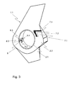
Fig. 3 shows a perspective view with details of a shroud of an empennage of a helicopter according to the invention, -
Fig. 4a shows a perspective view of a rotor blade of an empennage of a helicopter according to the invention, -
Fig. 4b shows a transversal cross sectional view of the rotor blade ofFig. 4a , -
Fig. 5a shows a composite structure applied to the empennage of a helicopter according to the invention, -
Fig. 5b shows an alternative composite structure applied to the empennage of a helicopter according to the invention, -
Fig. 5c shows a cross sectional view of a stator element of an empennage of a helicopter according to the invention, and -
Fig. 5d shows a cross sectional view of an alternative stator element of an empennage/fairing structure of a helicopter according to the invention. - According to
Fig. 1 atail boom 1 of a helicopter has an empennage 1.1 comprising a ducted counter-torque device with amulti-blade rotor 4 withrotor blades 3 inside a shroud 2.1. The empennage 1.1 comprises furthermore shrouded vertical tail fins 1.2 for assisting in yaw control. Therotor 4 is actuated by anactuation shaft 6 mounted at thetail boom 1. Two horizontal stabilizers 1.3 are situated left and right to thetail boom 1 for pitch control. Flow-straighteningstators 5 are positioned downstream from therotor 4 inside the shroud 2.1. The flow-straighteningstators 5 consist of stationary vanes disposed substantially in a star configuration parallel to the plane ofrotor 4. - The shroud 2.1 containing the
ducted tail rotor 4 is sheathed with a composite structure (cf.Fig. 5b ) for damping vibrations and broad-band noise produced from the operatingrotor 4. - According to
Fig. 2 corresponding features are referred to with the references ofFig. 1 . In addition to the composite structure sheathing the shroud 2.1 containing theducted tail rotor 4 the empennage 1.1 with the vertical tail fins 1.2 is sheathed with the composite structure according toFig. 5a or 5b as a vibration and sound damping structure increasing the damping effect concerning the vibrations and the sound of the operatingrotor 4. - According to
Fig. 3 corresponding features are referred to with the references ofFig. 1, 2 . The empennage 1.1 with the shroudedtail rotor 4 and the aerodynamically shaped and shrouded vertical tail fins 1.2 is sheathed with the composite structure. The outer wall 2.2 of the empennage 1.1 is provided withtop layers 7 containing an outer erosion protecting surface layer 7.1 made of a hard plastic and one elastomeric layer 7.2 and a first structural layer 7.3. The inner circumference of the shroud 2.1 is provided with atop layer structure 8 containing the outer erosion protecting surface layer 8.1 made of a hard plastic succeeded by two elastomeric layers 8.2 and 8.4 with an intermixed layer of a plastic composite structure 8.3, all fixed on a first structural layer 8.5 (seeFig. 5b ). - According to
Fig. 4a corresponding features are referred to with the references ofFig. 1 - 3 . Arotor blade 3 with an aerodynamic profile and cross sections changing along its span is sheathed with an elastomeric layer (cf.Fig. 4b ) between a radial outer cross section a-a and a radial inner cross section b-b, in order to optimize the damping effect for sound and vibration. - According to
Fig. 4b corresponding features are referred to with the references ofFig. 1 - 4a . At cross section a-a of the rotor blade 3 a kernel 3.1 is provided made either of metal, e.g. aluminium, or plastic composite. The kernel 3.1 as structural load carrying element serves to hold the loads of therotor blade 3. The elastomeric layer 3.2 used for damping the vibrations resulting from aerodynamic and mechanical loads is adapted to the aerodynamic profile of an outer erosion protection layer 3.3 with a smooth surface needed for minimum aerodynamic drag of therotor blade 3. - According to
Fig. 5a corresponding features are referred to with the references ofFig. 1 - 4b . Acomposite structure 7 forming the outer wall 2.2 of the empennage 1.1 is provided with an outer erosion protecting surface layer 7.1 made of a hard plastic like e.g. polyurethane, or preferably HMW-polyethylene, or even more preferably UHMW-polyethylene. Alternatively it may be a plastic composite material. The succeeding layer 7.2 is an elastomeric damping element made of material like ethylene-propylene-dien-caoutchouc (EPDM), ethylene-acrylate-caoutchouc (EAM), fluor-carbon-caoutchouc (FKM), natural caotchouc (NR), or elastomeric polyurethane (PU). The elastomeric material is treated with a cross linking agent, e.g. materials from the group of peroxides, amines or bi-phenoles. - Following this succeeding layer 7.2 is a structural layer 7.3 of the
composite structure 7 designed to hold any emerging loads. The elastomeric material is bonded to layers 7.1 and 7.3 by a thermal process with the help of a thermosetting resin, e.g. epoxy resin, phenol-formaldehyde-resin, polyester-resin or acrylate-resin. - According to
Fig. 5b corresponding features are referred to with the references ofFig. 1 - 5a . Thecomposite structure 8 for the inner circumference of the shroud 2.1 is built up with an outer erosion protecting surface layer 8.1 made of the hard plastic or the plastic composite material, a succeeding elastomeric layer 8.2 followed by a plastic composite structure 8.3. This layer of plastic composite structure 8.3 follows another elastomeric layer 8.4 in order to increase the damping effect of the inner circumference of the shroud 2.1. The succeeding layer 8.5 is either made from plastic composite or from metal. This succeeding layer 8.5 is capable to hold the inner circumference of the shroud 2.1 against emerging mechanical and aerodynamic loads. The layers 8.1, 8.3, and 8.5 are bonded to the elastomeric layers 8.2 and 8.4 by a thermal process with the help of a thermosetting resin, e.g. epoxy resin, phenol-formaldehyde-resin, polyester-resin or acrylate-resin. - According to
Fig. 5c a composite structure for the flow-straighteningstator elements 5 is built up with a load carrying structural component 5.4 towards the side 5.1, which is directly attacked by the rotating vortex while the side 5.2 with reduced aerodynamic load consists of a layer 5.3 of elastomeric material for damping the emerging vibrations and the produced sound. The structural component 5.4 of thestator element 5 on side 5.1 consists of metal or plastic composite material. - According to
Fig. 5d corresponding features are referred to with the references ofFig. 1 - 5c . The composite structure for the flow-straighteningstator elements 5 is built up with an additional outer layer 5.5 made of polished hard plastics for erosion protection and for reducing the aerodynamic drag. The additional outer layer 5.5 surrounds the structural component 5.4 of metal or plastic composite material and the layer 5.3 of elastomeric material. -
- 1
- tail boom
- 1.1
- empennage
- 1.2
- fins
- 1.3
- horizontal stabilizers
- 2.1
- shroud
- 2.2
- outer wall
- 3
- rotor blade
- 3.1
- kernel
- 3.2
- elastomeric layer
- 3.3
- erosion protection with smooth surface
- 4
- rotor with rotor hub
- 5
- stators
- 5.1
- attacked side
- 5.2
- side with reduced aerodynamic load
- 5.3
- layer of elastomeric material
- 5.4
- load carrying structural stator component
- 5.5
- outer layer of polished hard plastics for erosion protection
- 6
- actuation shaft
- 7, 8
- composite structure
- 7.1, 8.1
- erosion protecting surface layer
- 7.2, 8.2, 8.4
- succeeding elastomeric layer
- 7.3, 8.5
- load bearing structural layer
- 8.3
- plastic composite structure (made of one or more structural layers)
Claims (11)
- An empennage (1.1) of a helicopter comprises- a ducted counter-torque device with a multi-blade rotor (4) of rotor blades (3) and optional vertical tail fins (1.2), the rotor (4) being actuated by an actuation shaft (6) mounted along a tail boom, and- flow-straightening stators (5) of stationary vanes disposed substantially in a star configuration parallel to the rotor plane downstream from the rotor (4) inside a shroud (2.1) of the ducted counter-torque device, characterized in that at least the shroud (2.1) of the ducted counter-torque device is sheathed with a composite structure of an outer erosion protecting surface layer (7.1, 8.1) made of a hard plastic or a plastic composite material and at least one succeeding layer (7.2, 8.2) of an elastomeric damping material.
- The empennage (1.1) according to claim 1, characterized in that at least one load bearing structural layer (7.3, 8.5) is following the at least one succeeding layer (7.2, 8.2).
- The empennage (1.1) according to claim 1, characterized in that the shroud (2.1) of the ducted counter-torque device with the composite structure of the outer erosion protecting surface layer (8.1) made of the hard plastic or the layer of plastic composite material succeeded by one layer (8.2) of the elastomeric damping element is further succeeded by a layer of plastic composite material (8.3) being succeeded by one layer (8.4) of the elastomeric damping material succeeded by another layer (8.5) made of the plastic composite material or metal.
- The empennage (1.1) according to the preamble of claim 1,
characterized in that outer walls (2.2) are at least partly sheathed with the composite structure of- at least one outer erosion protecting surface layer (7.1) made of a hard plastic or a plastic composite material,- at least one succeeding layer (7.2) of an elastomeric damping material, and- load bearing structural layers (7.3) following the at least one succeeding layer (7.2). - The empennage (1.1) according to the preamble of claim 1,
characterized in that the rotor blades (3) of the ducted counter-torque device are sheathed with a composite structure of- at least one outer erosion protecting surface layer (3.3) made of a hard plastic or a plastic composite material, and- at least one succeeding layer (3.2) of an elastomeric damping material. - The empennage (1.1) according to the preamble of claim 1,
characterized in that the stationary vanes of the flow-straightening stators (5) of the ducted counter-torque device are sheathed with a composite structure of- at least one outer erosion protecting surface layer (5.5) made of a hard plastic or a plastic composite material, and- at least one succeeding layer (5.3) of an elastomeric damping material attached to the structural stator component (5.4). - The empennage (1.1) according to any of the preceding claims,
characterized in that the hard plastic is made of polyurethane, or preferably HMW-polyethylene, and/or even more preferably UHMW-polyethylene. - The empennage (1.1) according to any of the preceding claims,
characterized in that the elastomeric damping material is made of ethylene-propylene-dien-caotchouc (EPDM), ethylene-acrylate-caoutchouc (EAM), fluor-carbon-caoutchouc (FKM), natural caotchouc (NR) and/or elastomeric polyurethane (PU). - The empennage (1.1) according to any of the preceding claims,
characterized in that the composite structure (8) comprises essentially one or several layers of elastomeric material (8.2, 8.4) intermixed with either metallic sheets or plastic matrix material (8.3). - The empennage (1.1) according to any of the preceding claims,
characterized in that the elastomeric material is treated with a cross linking agent, e.g. materials from the group of peroxides, amines or bi-phenoles. - The empennage (1.1) according to any of the preceding claims,
characterized in that the layer of elastomeric material is bonded by a thermal process to the matrix material by help of a thermosetting resin, e.g. epoxy resin, phenol-formaldehyde-resin, polyester-resin or acrylate-resin.
Priority Applications (5)
| Application Number | Priority Date | Filing Date | Title |
|---|---|---|---|
| EP12400037.3A EP2706009B1 (en) | 2012-09-07 | 2012-09-07 | An empennage of a helicopter |
| CA2825490A CA2825490C (en) | 2012-09-07 | 2013-08-27 | An empennage of a helicopter |
| KR1020130106839A KR20140032908A (en) | 2012-09-07 | 2013-09-05 | An empennage of a helicopter |
| CN201310404561.3A CN103661917B (en) | 2012-09-07 | 2013-09-06 | The empennage of helicopter |
| US14/021,017 US9266602B2 (en) | 2012-09-07 | 2013-09-09 | Empennage of a helicopter |
Applications Claiming Priority (1)
| Application Number | Priority Date | Filing Date | Title |
|---|---|---|---|
| EP12400037.3A EP2706009B1 (en) | 2012-09-07 | 2012-09-07 | An empennage of a helicopter |
Publications (2)
| Publication Number | Publication Date |
|---|---|
| EP2706009A1 true EP2706009A1 (en) | 2014-03-12 |
| EP2706009B1 EP2706009B1 (en) | 2016-04-27 |
Family
ID=47172572
Family Applications (1)
| Application Number | Title | Priority Date | Filing Date |
|---|---|---|---|
| EP12400037.3A Active EP2706009B1 (en) | 2012-09-07 | 2012-09-07 | An empennage of a helicopter |
Country Status (4)
| Country | Link |
|---|---|
| US (1) | US9266602B2 (en) |
| EP (1) | EP2706009B1 (en) |
| KR (1) | KR20140032908A (en) |
| CA (1) | CA2825490C (en) |
Cited By (4)
| Publication number | Priority date | Publication date | Assignee | Title |
|---|---|---|---|---|
| EP2913271A1 (en) * | 2014-02-28 | 2015-09-02 | AIRBUS HELICOPTERS DEUTSCHLAND GmbH | Rotorcraft with at least one main rotor and at least one counter-torque rotor |
| WO2019022618A1 (en) * | 2017-07-24 | 2019-01-31 | Dotterel Technologies Limited | Shroud |
| US10814966B2 (en) | 2015-05-25 | 2020-10-27 | Dotterel Technologies Limited | Shroud for an aircraft |
| US11721352B2 (en) | 2018-05-16 | 2023-08-08 | Dotterel Technologies Limited | Systems and methods for audio capture |
Families Citing this family (8)
| Publication number | Priority date | Publication date | Assignee | Title |
|---|---|---|---|---|
| EP2878433B1 (en) * | 2013-11-29 | 2016-04-20 | AIRBUS HELICOPTERS DEUTSCHLAND GmbH | Shrouded rotary assembly from segmented composite for aircraft and method for its manufacture |
| EP2913270B1 (en) * | 2014-02-28 | 2016-02-24 | AIRBUS HELICOPTERS DEUTSCHLAND GmbH | Rotorcraft with at least one main rotor and at least one counter-torque rotor |
| DE102014006112A1 (en) * | 2014-04-29 | 2015-10-29 | Autogyro Ag | aircraft |
| US20180105262A1 (en) * | 2017-10-13 | 2018-04-19 | United States Of America As Represented By The Secretary Of The Of The Navy | Aircraft silencing system |
| EP3366584B1 (en) | 2017-02-27 | 2019-04-17 | AIRBUS HELICOPTERS DEUTSCHLAND GmbH | Pitch control device for a ducted tail rotor of a rotorcraft |
| KR20200067901A (en) | 2017-11-03 | 2020-06-12 | 우버 테크놀로지스, 인크. | VTOL M-wing configuration |
| DE102020201417A1 (en) | 2020-02-05 | 2021-08-05 | kopter germany GmbH | Rotor system for an aircraft |
| US11772785B2 (en) * | 2020-12-01 | 2023-10-03 | Textron Innovations Inc. | Tail rotor configurations for rotorcraft yaw control systems |
Citations (12)
| Publication number | Priority date | Publication date | Assignee | Title |
|---|---|---|---|---|
| EP0562527A1 (en) | 1992-03-24 | 1993-09-29 | Kawasaki Jukogyo Kabushiki Kaisha | Tail rotor for rotor craft |
| EP0680873A1 (en) | 1994-05-04 | 1995-11-08 | Eurocopter France | Anti-torque device with shrouded rotor and straightening stator and slanted guide vanes |
| EP0680871A1 (en) | 1994-05-04 | 1995-11-08 | Eurocopter France | Anti-torque device with shrouded rotor and phase modulation of the rotor blades positions for helicopters |
| US5588618A (en) | 1994-05-04 | 1996-12-31 | Eurocopter France | Counter-torque device with rotor and flow-straightening stator, both of which are ducted, and phase modulation of the blades of the rotor, for helicopter |
| US6206136B1 (en) * | 1999-07-23 | 2001-03-27 | General Electric Company | Acoustic liner and method of making an acoustic liner |
| US6851515B2 (en) * | 2000-10-20 | 2005-02-08 | Eurocopter | Soundproofing panel, in particular structural or lining panel for a rotorcraft |
| EP1533521A1 (en) * | 2003-11-21 | 2005-05-25 | General Electric Company | Wind power plant with reduced noise emission |
| WO2006122749A1 (en) * | 2005-05-17 | 2006-11-23 | Gummiwerk Kraiburg Gmbh & Co. Kg | Composite structure from thermosetting resins and elastomers, method for producing the same and use of said composite structure |
| US20090014581A1 (en) * | 2004-07-16 | 2009-01-15 | Bell Helicopter Textron Inc. | Counter-Torque Device for a Helicopter |
| EP2071561A2 (en) | 2007-12-14 | 2009-06-17 | Eurocopter | Absorbent structure for reducing the noise generated in particular by a rotor and fairing comprising such a structure |
| WO2010118860A2 (en) | 2009-04-14 | 2010-10-21 | Gummiwerk Kraiburg Gmbh & Co. Kg | Composite components and heat-curing resins and elastomers |
| US8061962B2 (en) | 2008-01-30 | 2011-11-22 | Eurocopter | Method of optimizing a ducted anti-torque rotor of a rotorcraft, in particular a helicopter, to minimize acoustic annoyance, and a ducted anti-torque rotor obtained thereby |
Family Cites Families (2)
| Publication number | Priority date | Publication date | Assignee | Title |
|---|---|---|---|---|
| FR2719553B1 (en) * | 1994-05-04 | 1996-07-26 | Eurocopter France | Anti-torque device with rear rotor and shrouded stator for helicopter. |
| FR2879496B1 (en) | 2004-12-16 | 2008-12-12 | Eurocopter France | METHOD AND DEVICE FOR MANUFACTURING A HELICOPTER ROTOR CARENE, AND CARENE OBTAINED |
-
2012
- 2012-09-07 EP EP12400037.3A patent/EP2706009B1/en active Active
-
2013
- 2013-08-27 CA CA2825490A patent/CA2825490C/en active Active
- 2013-09-05 KR KR1020130106839A patent/KR20140032908A/en not_active Application Discontinuation
- 2013-09-09 US US14/021,017 patent/US9266602B2/en not_active Expired - Fee Related
Patent Citations (13)
| Publication number | Priority date | Publication date | Assignee | Title |
|---|---|---|---|---|
| EP0562527A1 (en) | 1992-03-24 | 1993-09-29 | Kawasaki Jukogyo Kabushiki Kaisha | Tail rotor for rotor craft |
| EP0680873A1 (en) | 1994-05-04 | 1995-11-08 | Eurocopter France | Anti-torque device with shrouded rotor and straightening stator and slanted guide vanes |
| EP0680871A1 (en) | 1994-05-04 | 1995-11-08 | Eurocopter France | Anti-torque device with shrouded rotor and phase modulation of the rotor blades positions for helicopters |
| US5588618A (en) | 1994-05-04 | 1996-12-31 | Eurocopter France | Counter-torque device with rotor and flow-straightening stator, both of which are ducted, and phase modulation of the blades of the rotor, for helicopter |
| US5634611A (en) | 1994-05-04 | 1997-06-03 | Eurocopter France | Counter-torque device with rotor and flow straightening stator, both of which are ducted, and inclined flow-straightening vanes |
| US6206136B1 (en) * | 1999-07-23 | 2001-03-27 | General Electric Company | Acoustic liner and method of making an acoustic liner |
| US6851515B2 (en) * | 2000-10-20 | 2005-02-08 | Eurocopter | Soundproofing panel, in particular structural or lining panel for a rotorcraft |
| EP1533521A1 (en) * | 2003-11-21 | 2005-05-25 | General Electric Company | Wind power plant with reduced noise emission |
| US20090014581A1 (en) * | 2004-07-16 | 2009-01-15 | Bell Helicopter Textron Inc. | Counter-Torque Device for a Helicopter |
| WO2006122749A1 (en) * | 2005-05-17 | 2006-11-23 | Gummiwerk Kraiburg Gmbh & Co. Kg | Composite structure from thermosetting resins and elastomers, method for producing the same and use of said composite structure |
| EP2071561A2 (en) | 2007-12-14 | 2009-06-17 | Eurocopter | Absorbent structure for reducing the noise generated in particular by a rotor and fairing comprising such a structure |
| US8061962B2 (en) | 2008-01-30 | 2011-11-22 | Eurocopter | Method of optimizing a ducted anti-torque rotor of a rotorcraft, in particular a helicopter, to minimize acoustic annoyance, and a ducted anti-torque rotor obtained thereby |
| WO2010118860A2 (en) | 2009-04-14 | 2010-10-21 | Gummiwerk Kraiburg Gmbh & Co. Kg | Composite components and heat-curing resins and elastomers |
Non-Patent Citations (1)
| Title |
|---|
| FRANK KAMEIER: "Experimentelle Untersuchung zur Entstehung und Minderung des Blattspitzen-Wirbellärms axialer Str6mungsmaschinen", 1994, DISS. TU BERLIN |
Cited By (5)
| Publication number | Priority date | Publication date | Assignee | Title |
|---|---|---|---|---|
| EP2913271A1 (en) * | 2014-02-28 | 2015-09-02 | AIRBUS HELICOPTERS DEUTSCHLAND GmbH | Rotorcraft with at least one main rotor and at least one counter-torque rotor |
| US10814966B2 (en) | 2015-05-25 | 2020-10-27 | Dotterel Technologies Limited | Shroud for an aircraft |
| WO2019022618A1 (en) * | 2017-07-24 | 2019-01-31 | Dotterel Technologies Limited | Shroud |
| US11097828B2 (en) | 2017-07-24 | 2021-08-24 | Dotterel Technologies Limited | Shroud |
| US11721352B2 (en) | 2018-05-16 | 2023-08-08 | Dotterel Technologies Limited | Systems and methods for audio capture |
Also Published As
| Publication number | Publication date |
|---|---|
| CA2825490C (en) | 2015-12-01 |
| CA2825490A1 (en) | 2014-03-07 |
| CN103661917A (en) | 2014-03-26 |
| US20140070051A1 (en) | 2014-03-13 |
| KR20140032908A (en) | 2014-03-17 |
| EP2706009B1 (en) | 2016-04-27 |
| US9266602B2 (en) | 2016-02-23 |
Similar Documents
| Publication | Publication Date | Title |
|---|---|---|
| EP2706009B1 (en) | An empennage of a helicopter | |
| CN107109962B (en) | Blower-casting for aircraft engine | |
| EP2674355B1 (en) | Methods and apparatus for reducing noise in reinforced skin structures | |
| WO2008091299A2 (en) | High performance outboard section for rotor blades | |
| CN101389471A (en) | Protection device | |
| US20110182730A1 (en) | Wind turbine blade with damping element for edgewise vibrations | |
| US8020663B2 (en) | Method for reducing the noise generated by a hole under a high energy gas flow | |
| US20180009201A1 (en) | Foam based non-newtonian materials for use with aircraft engine components | |
| EP2160325B1 (en) | Helicopter rotor comprising a vibration damper | |
| US10442531B2 (en) | Rotor damping | |
| EP2962935B1 (en) | Helicopter with noise and vibration damping transmission mounting | |
| JP2010100283A (en) | Helicopter | |
| US10040545B2 (en) | Rotor dome, a rotor, and a rotorcraft | |
| EP1007406A2 (en) | Vibration isolator for rotorcraft | |
| FR2954273A1 (en) | ROTOR CARRIER STRUCTURE AND FLYING APPARATUS PROVIDED WITH SUCH A CARRIER STRUCTURE | |
| US20170334552A1 (en) | Aircraft load and vibration attenuation | |
| EP2913269B1 (en) | Rotorcraft with at least one main rotor and at least one counter-torque rotor | |
| EP3228536A1 (en) | Composite insulation for reducing broadband aircraft noise | |
| US20150114751A1 (en) | Soundproofing covering having resonators, a panel provided with the covering, and an aircraft | |
| RU2575969C2 (en) | Helicopter tail assembly | |
| US20160176532A1 (en) | Propeller for an aircraft turbomachine, including a blade retaining structure through which the aerodynamic part of each blade passes | |
| CN103661917B (en) | The empennage of helicopter | |
| EP3476728A1 (en) | Rotor for a hover-capable aircraft and method for containment of vibrations transmitted to the mast of a rotor of a hover-capable aircraft | |
| EP4118357B1 (en) | Passive vibration damping device for aircraft | |
| US20060032973A1 (en) | Lightweight structural damping assembly |
Legal Events
| Date | Code | Title | Description |
|---|---|---|---|
| PUAI | Public reference made under article 153(3) epc to a published international application that has entered the european phase |
Free format text: ORIGINAL CODE: 0009012 |
|
| AK | Designated contracting states |
Kind code of ref document: A1 Designated state(s): AL AT BE BG CH CY CZ DE DK EE ES FI FR GB GR HR HU IE IS IT LI LT LU LV MC MK MT NL NO PL PT RO RS SE SI SK SM TR |
|
| AX | Request for extension of the european patent |
Extension state: BA ME |
|
| RAP1 | Party data changed (applicant data changed or rights of an application transferred) |
Owner name: AIRBUS HELICOPTERS DEUTSCHLAND GMBH |
|
| 17P | Request for examination filed |
Effective date: 20140521 |
|
| RBV | Designated contracting states (corrected) |
Designated state(s): AL AT BE BG CH CY CZ DE DK EE ES FI FR GB GR HR HU IE IS IT LI LT LU LV MC MK MT NL NO PL PT RO RS SE SI SK SM TR |
|
| RIC1 | Information provided on ipc code assigned before grant |
Ipc: B64C 27/00 20060101AFI20151215BHEP Ipc: B64D 45/00 20060101ALI20151215BHEP Ipc: B64C 27/82 20060101ALI20151215BHEP |
|
| GRAP | Despatch of communication of intention to grant a patent |
Free format text: ORIGINAL CODE: EPIDOSNIGR1 |
|
| INTG | Intention to grant announced |
Effective date: 20160126 |
|
| GRAS | Grant fee paid |
Free format text: ORIGINAL CODE: EPIDOSNIGR3 |
|
| GRAA | (expected) grant |
Free format text: ORIGINAL CODE: 0009210 |
|
| AK | Designated contracting states |
Kind code of ref document: B1 Designated state(s): AL AT BE BG CH CY CZ DE DK EE ES FI FR GB GR HR HU IE IS IT LI LT LU LV MC MK MT NL NO PL PT RO RS SE SI SK SM TR |
|
| REG | Reference to a national code |
Ref country code: GB Ref legal event code: FG4D |
|
| REG | Reference to a national code |
Ref country code: CH Ref legal event code: EP |
|
| REG | Reference to a national code |
Ref country code: AT Ref legal event code: REF Ref document number: 794463 Country of ref document: AT Kind code of ref document: T Effective date: 20160515 |
|
| REG | Reference to a national code |
Ref country code: IE Ref legal event code: FG4D |
|
| REG | Reference to a national code |
Ref country code: DE Ref legal event code: R096 Ref document number: 602012017626 Country of ref document: DE |
|
| REG | Reference to a national code |
Ref country code: LT Ref legal event code: MG4D |
|
| REG | Reference to a national code |
Ref country code: NL Ref legal event code: MP Effective date: 20160427 |
|
| REG | Reference to a national code |
Ref country code: AT Ref legal event code: MK05 Ref document number: 794463 Country of ref document: AT Kind code of ref document: T Effective date: 20160427 |
|
| REG | Reference to a national code |
Ref country code: FR Ref legal event code: PLFP Year of fee payment: 5 |
|
| PG25 | Lapsed in a contracting state [announced via postgrant information from national office to epo] |
Ref country code: NL Free format text: LAPSE BECAUSE OF FAILURE TO SUBMIT A TRANSLATION OF THE DESCRIPTION OR TO PAY THE FEE WITHIN THE PRESCRIBED TIME-LIMIT Effective date: 20160427 |
|
| PG25 | Lapsed in a contracting state [announced via postgrant information from national office to epo] |
Ref country code: PL Free format text: LAPSE BECAUSE OF FAILURE TO SUBMIT A TRANSLATION OF THE DESCRIPTION OR TO PAY THE FEE WITHIN THE PRESCRIBED TIME-LIMIT Effective date: 20160427 Ref country code: NO Free format text: LAPSE BECAUSE OF FAILURE TO SUBMIT A TRANSLATION OF THE DESCRIPTION OR TO PAY THE FEE WITHIN THE PRESCRIBED TIME-LIMIT Effective date: 20160727 Ref country code: FI Free format text: LAPSE BECAUSE OF FAILURE TO SUBMIT A TRANSLATION OF THE DESCRIPTION OR TO PAY THE FEE WITHIN THE PRESCRIBED TIME-LIMIT Effective date: 20160427 Ref country code: LT Free format text: LAPSE BECAUSE OF FAILURE TO SUBMIT A TRANSLATION OF THE DESCRIPTION OR TO PAY THE FEE WITHIN THE PRESCRIBED TIME-LIMIT Effective date: 20160427 |
|
| PG25 | Lapsed in a contracting state [announced via postgrant information from national office to epo] |
Ref country code: AT Free format text: LAPSE BECAUSE OF FAILURE TO SUBMIT A TRANSLATION OF THE DESCRIPTION OR TO PAY THE FEE WITHIN THE PRESCRIBED TIME-LIMIT Effective date: 20160427 Ref country code: ES Free format text: LAPSE BECAUSE OF FAILURE TO SUBMIT A TRANSLATION OF THE DESCRIPTION OR TO PAY THE FEE WITHIN THE PRESCRIBED TIME-LIMIT Effective date: 20160427 Ref country code: HR Free format text: LAPSE BECAUSE OF FAILURE TO SUBMIT A TRANSLATION OF THE DESCRIPTION OR TO PAY THE FEE WITHIN THE PRESCRIBED TIME-LIMIT Effective date: 20160427 Ref country code: GR Free format text: LAPSE BECAUSE OF FAILURE TO SUBMIT A TRANSLATION OF THE DESCRIPTION OR TO PAY THE FEE WITHIN THE PRESCRIBED TIME-LIMIT Effective date: 20160728 Ref country code: SE Free format text: LAPSE BECAUSE OF FAILURE TO SUBMIT A TRANSLATION OF THE DESCRIPTION OR TO PAY THE FEE WITHIN THE PRESCRIBED TIME-LIMIT Effective date: 20160427 Ref country code: PT Free format text: LAPSE BECAUSE OF FAILURE TO SUBMIT A TRANSLATION OF THE DESCRIPTION OR TO PAY THE FEE WITHIN THE PRESCRIBED TIME-LIMIT Effective date: 20160829 Ref country code: RS Free format text: LAPSE BECAUSE OF FAILURE TO SUBMIT A TRANSLATION OF THE DESCRIPTION OR TO PAY THE FEE WITHIN THE PRESCRIBED TIME-LIMIT Effective date: 20160427 Ref country code: LV Free format text: LAPSE BECAUSE OF FAILURE TO SUBMIT A TRANSLATION OF THE DESCRIPTION OR TO PAY THE FEE WITHIN THE PRESCRIBED TIME-LIMIT Effective date: 20160427 |
|
| PG25 | Lapsed in a contracting state [announced via postgrant information from national office to epo] |
Ref country code: BE Free format text: LAPSE BECAUSE OF FAILURE TO SUBMIT A TRANSLATION OF THE DESCRIPTION OR TO PAY THE FEE WITHIN THE PRESCRIBED TIME-LIMIT Effective date: 20160427 |
|
| REG | Reference to a national code |
Ref country code: DE Ref legal event code: R097 Ref document number: 602012017626 Country of ref document: DE |
|
| PG25 | Lapsed in a contracting state [announced via postgrant information from national office to epo] |
Ref country code: DK Free format text: LAPSE BECAUSE OF FAILURE TO SUBMIT A TRANSLATION OF THE DESCRIPTION OR TO PAY THE FEE WITHIN THE PRESCRIBED TIME-LIMIT Effective date: 20160427 Ref country code: SK Free format text: LAPSE BECAUSE OF FAILURE TO SUBMIT A TRANSLATION OF THE DESCRIPTION OR TO PAY THE FEE WITHIN THE PRESCRIBED TIME-LIMIT Effective date: 20160427 Ref country code: RO Free format text: LAPSE BECAUSE OF FAILURE TO SUBMIT A TRANSLATION OF THE DESCRIPTION OR TO PAY THE FEE WITHIN THE PRESCRIBED TIME-LIMIT Effective date: 20160427 Ref country code: CZ Free format text: LAPSE BECAUSE OF FAILURE TO SUBMIT A TRANSLATION OF THE DESCRIPTION OR TO PAY THE FEE WITHIN THE PRESCRIBED TIME-LIMIT Effective date: 20160427 Ref country code: EE Free format text: LAPSE BECAUSE OF FAILURE TO SUBMIT A TRANSLATION OF THE DESCRIPTION OR TO PAY THE FEE WITHIN THE PRESCRIBED TIME-LIMIT Effective date: 20160427 |
|
| PG25 | Lapsed in a contracting state [announced via postgrant information from national office to epo] |
Ref country code: SM Free format text: LAPSE BECAUSE OF FAILURE TO SUBMIT A TRANSLATION OF THE DESCRIPTION OR TO PAY THE FEE WITHIN THE PRESCRIBED TIME-LIMIT Effective date: 20160427 |
|
| PLBE | No opposition filed within time limit |
Free format text: ORIGINAL CODE: 0009261 |
|
| STAA | Information on the status of an ep patent application or granted ep patent |
Free format text: STATUS: NO OPPOSITION FILED WITHIN TIME LIMIT |
|
| 26N | No opposition filed |
Effective date: 20170130 |
|
| PG25 | Lapsed in a contracting state [announced via postgrant information from national office to epo] |
Ref country code: MC Free format text: LAPSE BECAUSE OF FAILURE TO SUBMIT A TRANSLATION OF THE DESCRIPTION OR TO PAY THE FEE WITHIN THE PRESCRIBED TIME-LIMIT Effective date: 20160427 |
|
| REG | Reference to a national code |
Ref country code: CH Ref legal event code: PL |
|
| PG25 | Lapsed in a contracting state [announced via postgrant information from national office to epo] |
Ref country code: SI Free format text: LAPSE BECAUSE OF FAILURE TO SUBMIT A TRANSLATION OF THE DESCRIPTION OR TO PAY THE FEE WITHIN THE PRESCRIBED TIME-LIMIT Effective date: 20160427 |
|
| REG | Reference to a national code |
Ref country code: IE Ref legal event code: MM4A |
|
| PG25 | Lapsed in a contracting state [announced via postgrant information from national office to epo] |
Ref country code: CH Free format text: LAPSE BECAUSE OF NON-PAYMENT OF DUE FEES Effective date: 20160930 Ref country code: IE Free format text: LAPSE BECAUSE OF NON-PAYMENT OF DUE FEES Effective date: 20160907 Ref country code: LI Free format text: LAPSE BECAUSE OF NON-PAYMENT OF DUE FEES Effective date: 20160930 |
|
| PG25 | Lapsed in a contracting state [announced via postgrant information from national office to epo] |
Ref country code: LU Free format text: LAPSE BECAUSE OF NON-PAYMENT OF DUE FEES Effective date: 20160907 |
|
| REG | Reference to a national code |
Ref country code: FR Ref legal event code: PLFP Year of fee payment: 6 |
|
| PG25 | Lapsed in a contracting state [announced via postgrant information from national office to epo] |
Ref country code: HU Free format text: LAPSE BECAUSE OF FAILURE TO SUBMIT A TRANSLATION OF THE DESCRIPTION OR TO PAY THE FEE WITHIN THE PRESCRIBED TIME-LIMIT; INVALID AB INITIO Effective date: 20120907 Ref country code: CY Free format text: LAPSE BECAUSE OF FAILURE TO SUBMIT A TRANSLATION OF THE DESCRIPTION OR TO PAY THE FEE WITHIN THE PRESCRIBED TIME-LIMIT Effective date: 20160427 |
|
| PG25 | Lapsed in a contracting state [announced via postgrant information from national office to epo] |
Ref country code: MT Free format text: LAPSE BECAUSE OF NON-PAYMENT OF DUE FEES Effective date: 20160930 Ref country code: IS Free format text: LAPSE BECAUSE OF FAILURE TO SUBMIT A TRANSLATION OF THE DESCRIPTION OR TO PAY THE FEE WITHIN THE PRESCRIBED TIME-LIMIT Effective date: 20160427 Ref country code: MK Free format text: LAPSE BECAUSE OF FAILURE TO SUBMIT A TRANSLATION OF THE DESCRIPTION OR TO PAY THE FEE WITHIN THE PRESCRIBED TIME-LIMIT Effective date: 20160427 |
|
| PG25 | Lapsed in a contracting state [announced via postgrant information from national office to epo] |
Ref country code: BG Free format text: LAPSE BECAUSE OF FAILURE TO SUBMIT A TRANSLATION OF THE DESCRIPTION OR TO PAY THE FEE WITHIN THE PRESCRIBED TIME-LIMIT Effective date: 20160427 |
|
| REG | Reference to a national code |
Ref country code: FR Ref legal event code: PLFP Year of fee payment: 7 |
|
| PG25 | Lapsed in a contracting state [announced via postgrant information from national office to epo] |
Ref country code: AL Free format text: LAPSE BECAUSE OF FAILURE TO SUBMIT A TRANSLATION OF THE DESCRIPTION OR TO PAY THE FEE WITHIN THE PRESCRIBED TIME-LIMIT Effective date: 20160427 Ref country code: TR Free format text: LAPSE BECAUSE OF FAILURE TO SUBMIT A TRANSLATION OF THE DESCRIPTION OR TO PAY THE FEE WITHIN THE PRESCRIBED TIME-LIMIT Effective date: 20160427 |
|
| PGFP | Annual fee paid to national office [announced via postgrant information from national office to epo] |
Ref country code: GB Payment date: 20220920 Year of fee payment: 11 Ref country code: DE Payment date: 20220920 Year of fee payment: 11 |
|
| PGFP | Annual fee paid to national office [announced via postgrant information from national office to epo] |
Ref country code: FR Payment date: 20220922 Year of fee payment: 11 |
|
| PGFP | Annual fee paid to national office [announced via postgrant information from national office to epo] |
Ref country code: IT Payment date: 20220926 Year of fee payment: 11 |
|
| P01 | Opt-out of the competence of the unified patent court (upc) registered |
Effective date: 20230530 |