EP0680873A1 - Anti-torque device with shrouded rotor and straightening stator and slanted guide vanes - Google Patents
Anti-torque device with shrouded rotor and straightening stator and slanted guide vanes Download PDFInfo
- Publication number
- EP0680873A1 EP0680873A1 EP95400998A EP95400998A EP0680873A1 EP 0680873 A1 EP0680873 A1 EP 0680873A1 EP 95400998 A EP95400998 A EP 95400998A EP 95400998 A EP95400998 A EP 95400998A EP 0680873 A1 EP0680873 A1 EP 0680873A1
- Authority
- EP
- European Patent Office
- Prior art keywords
- rotor
- blades
- vein
- approximately
- axis
- Prior art date
- Legal status (The legal status is an assumption and is not a legal conclusion. Google has not performed a legal analysis and makes no representation as to the accuracy of the status listed.)
- Granted
Links
Images


Classifications
-
- B—PERFORMING OPERATIONS; TRANSPORTING
- B64—AIRCRAFT; AVIATION; COSMONAUTICS
- B64C—AEROPLANES; HELICOPTERS
- B64C27/00—Rotorcraft; Rotors peculiar thereto
- B64C27/82—Rotorcraft; Rotors peculiar thereto characterised by the provision of an auxiliary rotor or fluid-jet device for counter-balancing lifting rotor torque or changing direction of rotorcraft
- B64C2027/8254—Shrouded tail rotors, e.g. "Fenestron" fans
Definitions
- the invention relates to improvements made to anti-torque devices with a rear rotor and streamlined stator stator for helicopters, in which the stator stator, comprising fixed blades with aerodynamic profile, is fixed downstream of the rotor in the flow stream of air arranged transversely in the hull integrated into the structure of the rear assemblies of a helicopter, such as the tail boom, the tailplane or a fin.
- the improvements made by the invention to anti-torque devices of this type make it possible to improve their acoustic and / or aerodynamic performance, to provide a significant reduction in noise and associated acoustic nuisances, as well as better yaw control, respectively.
- a faired anti-torque rotor prevents any risk of bodily injury on the ground, because it is protected inside the vein in the tail boom, unlike a conventional tail rotor.
- This arrangement of the faired anti-torque rotor also allows it to avoid ingesting any damaging object that may be entrained in the wake of the main rotor.
- the faired anti-torque rotor In flight or when maneuvering near the ground or on the ground, the faired anti-torque rotor is naturally protected by its fairing, which prevents any risk of impact with external obstacles such as power lines, branches, constructions or even the ground, which can cause fatal damage to a conventional tail rotor, and therefore the loss of the helicopter, with all the consequences that ensue for the crew.
- a faired anti-torque rotor eliminates a certain number of problems which appear when equipping a helicopter with a conventional rear rotor.
- the diameter of a conventional rear rotor is generally large.
- a conventional rear rotor is generally mounted at a high point on the fin, which creates a moment of roll on the helicopter, which must be balance, and generates parasitic drag in high speed forward flight. Due to its exposed position, a conventional tail rotor can be highly stressed by loads dynamics limiting its lifespan.
- the aerodynamic blocking effect of a conventional tail rotor due to the mask of the fin, generates a strongly asymmetrical behavior in crosswinds, and harmful impulse periodic aerodynamic loads.
- a faired tail rotor does not have these disadvantages. In general, it can easily be arranged so that its axis substantially intersects the roll axis of the helicopter, or is close to this roll axis, so that it does not create a parasitic roll moment. In addition, due to its fairing, it produces approximately half of its total anti-torque thrust by the sole phenomenon of suction by the collector, at the entrance to the vein that houses it. This makes it possible to discharge all the blades of the rotor, which practically do not undergo dynamic stresses, because of the effective protection provided by the fairing against external variations of the air flow, coming from the main rotor. and the fuselage of the helicopter.
- the faired anti-torque rotor In forward flight at high speed of the latter, the faired anti-torque rotor is unloaded, which correspondingly reduces its contribution to the overall drag of the device.
- the vertical fin possibly fitted with a turning flap, provides the anti-torque function.
- no drift or tail plane hinders the operation of the faired anti-torque rotor, which gives it maximum efficiency in crosswinds and during rapid maneuvers around the yaw axis.
- the diffusion ratio is close to 1, and can be increased by increasing the angle of divergence of a frustoconical part of the diffuser that the vein can have downstream of the plane. of rotation of the rotor blades, as described for example in American patent US Pat. No. 5,131,604, where this angle of divergence is limited to 5 °.
- the contraction of the wake on a conventional rear rotor freezes the diffusion ratio at 1/2, which prevents any improvement in performance by means of this parameter.
- a faired tail rotor still takes advantage of its positioning in a fairing vein: unlike a conventional tail rotor, which radiates noise in all directions, the detectability of a faired tail rotor towards the 'Forward and backward, in the forward direction of the helicopter, is greatly reduced due to the fairing.
- the combination of an angular speed of rotation ⁇ and a higher number of blades b on a faired anti-torque rotor than on a conventional tail rotor produces a "blade passage frequency" bx ⁇ and its frequencies multiple nb ⁇ which are much higher frequencies of concentration of the acoustic energy than for a traditional tail rotor, and typically in the range of frequencies from 400 Hz to 2000 Hz.
- these frequencies are very quickly attenuated in the atmosphere, while the very low frequencies of acoustic energy concentration of a conventional tail rotor propagate far.
- a drawback of faired anti-torque rotors is that raising the level of the acoustic energy concentration frequencies places the latter in a frequency zone of maximum sensitivity of the human ear.
- the very impulsive aspect of a faired anti-torque rotor noise spectrum is translated by a characteristic hiss very painful to the human ear, and which is strongly penalized by the criteria of acoustic certification by means of "corrections of pure sounds or emerging lines".
- the acoustic signature characteristic of a faired anti-torque rotor is also a harmful phenomenon, facilitating the identification of the helicopter.
- the overall level of dissipated acoustic energy is the second main factor in judging the quality of the acoustic level of a helicopter.
- the aerodynamic operation of a faired anti-torque rotor, with a high number of blades and for which the anti-torque thrust is provided for half by suction results in a lower blade load than that experienced by the blades of a conventional tail rotor, and therefore a lower load noise level.
- the presence of fixed obstacles in the fairing of the anti-torque rotor, downstream of the latter, such as for example the support arms of a rear gearbox associated with a collective pitch control mechanism of the blades, and on which the rotor is mounted in rotation, or even as a stator rectifier with fixed profiled blades, for example, can greatly increase the level of radiated acoustic energy.
- US Pat. No. 5,131,604 proposes that the three support arms be of elliptical section, one being radial and aligned with the longitudinal axis of the helicopter and the other two parallel to the vertical axis of the fairing, but offset towards the rear, the spacing, along the axis of the vein, between the plane of rotation of the rotor and the support arms being 2 to 2.5 times the minor axis of the ellipse of the section of the arms.
- These shapes and arrangements make it possible to significantly reduce the lines of acoustic interactions between the rotor and the support arms, for an eight-blade rotor whose peripheral speed is limited to approximately 225 m / s.
- the propeller has an even number of blades and greater than or equal to four, the blades being diametrically opposite two by two, and the pairs of blades being arranged offset with respect to each other with an angular deviation pitch of between approximately 15 ° and 50 °, so that the levels of the rotational noise harmonics are weakened by interference .
- An object of the invention is to propose improvements for the production of an anti-torque device with rotor and stator rectifier streamlined with minimal noise pollution, intended to equip a helicopter propelled by means of a single main rotor, while retaining , or even by improving, the aerodynamic performance of the device fairing anti-torque, compared to known assemblies of this type.
- an object of the invention is to propose a configuration and / or an arrangement of the rectifier according to the geometry of the rotor to minimize the interaction noise. , by reducing the radiated acoustic energy.
- Another object of the invention is to provide a streamlined vein configuration improving the aerodynamic performance of the anti-torque device, whether or not the rotor blades are evenly distributed angularly, to increase the level of thrust at given power, and decrease the noise caused by the flow of air in the vein.
- the invention aims to provide an anti-torque device with a faired rotor and stator rectifier, which is better suited to the various requirements of practice than the known faired anti-torque devices.
- an anti-torque device for a helicopter comprising a multi-blade variable pitch rotor mounted to rotate and substantially coaxial in an air flow stream of substantially axis transverse to the helicopter and passing through a hull integrated in the rear part of the helicopter, so that the pitch change axes of the blades move in a plane of rotation substantially perpendicular to the axis of the faired vein, as well as '' a stator rectifier fixed in the vein downstream of the rotor and comprising fixed blades arranged substantially in a star around the axis of the vein and each having an asymmetrical aerodynamic profile including the camber and the angular setting relative to the axis of the vein are such that the blades straighten the air flow downstream of the rotor substantially parallel to the axis of the vein, and which characterized in that the blades of the straightener are each inclined in the radial direction, preferably from an angle of about 1 ° to about 25
- This orientation is simultaneously favorable to the resumption of the torque, acting, in reaction to the rotation of the rotor, on a central body substantially coaxial with the vein, enclosing the rotor drive members and the collective pitch control members of the blades of the latter, and that the blades of the stator can thus advantageously support in the vein.
- each stator vane makes a non-zero angle relative to the plane of rotation of the rotor blades, while being inclined towards the exit of the vein, makes it possible to increase the distance which separates the plane of rotation of the blades.
- this distance is advantageous, in particularly if the chord c is measured at the start of the profiled running part of the blade, to obtain a good compromise between the level of radiated acoustic energy and the aerodynamic efficiency of the rectifier, and to favor its arrangement in the vein of the device anti-torque, and in particular the anchoring of its blades in the streamlined wall of the vein, as well as to ensure a good positioning of the rotor in the vein, by means of the rear gearbox supported in it by the blades.
- the blades fulfill their good function of supporting the central body simultaneously and their function of straightening the air flow passing through the vein, it is advantageous that they have an aerodynamic profile of the NACA 65 type, with a relative thickness. comprised between approximately 8% and approximately 12%, an angular setting on the axis of the vein comprised between approximately 2 ° and approximately 2.5 °, oriented to prick, and a camber comprised between approximately 20 ° and approximately 28 °.
- the thickness thus chosen is a compromise between the smallest possible relative thickness, in order to reduce both the load noise and the thickness of the rectifier working in the wake of the rotating blades, and a thickness sufficient to maintain the body supporting the rotor and enclosing the rear gearbox and the collective control of the pitch of the blades, which are thus secured to the rear assembly of the helicopter, comprising the end of the tail boom and a tail or a tail fin the helicopter, while being subjected to static and dynamic force fields.
- this arm is advantageously placed in the vein substantially in the place of one of the blades of the rectifier, the profiled blades of which are advantageously in number at least equal to the number of blades of the rotor decreased by one unit.
- a reduction in the noise nuisance and an increase in the aerodynamic performance of an anti-torque device with a faired rotor can also be obtained by a particular geometrical configuration of the vein, when the azimuthal modulation of the blades is irregular or regular. , and that the rotor is or is not associated with a rectifier.
- the vein comprises two parts, one of which is a manifold, corresponding to the part of the vein located upstream of the plane of rotation of the rotor, and the other is a diffuser, corresponding to the part of the vein.
- the manifold located downstream of the plane of rotation of the rotor, the manifold comprising an inlet convergent, delimited by an annular wall convex upstream and rounded with a constant radius Rc, and which extends towards the plane of rotation of the rotor by a cylindrical zone of a first length L1
- the diffuser comprising, from the plane of rotation of the rotor downstream, a cylindrical zone of a second length L2, extending the cylindrical zone of the manifold, then a frustoconical diverging of half angle at the top ⁇ , and a divergent outlet delimited by a convex annular wall downstream, and rounded with radius r.
- the position of the plane of rotation of the rotor in this cylindrical part is defined as a function of the chord c of the blades of the rotor, of their positive pitch range, of the distance a between their leading edge and the axis of change. pitch, and the maximum deformation f of the blade, characterizing its stiffness in flapping, so that the lengths L1 and L2 of the cylindrical zones are such that: L1> a sin ( ⁇ max) + f and L2 ⁇ (c - a) sin ( ⁇ max), where ⁇ max is the maximum positive pitch angle of the blades of the rotor.
- the lengths L1 and L2 of the cylindrical zones of the collector and of the diffuser respectively are between approximately 2% and approximately 8%, and between approximately 1% and approximately 3.5% of the diameter of the measured vein. in its cylindrical part.
- the vein has a cylindrical part, as soon as it has a converging inlet manifold delimited by a convex and rounded annular wall with a constant radius Rc, this radius is approximately 8% of the diameter of the vein measured at its neck, in its tightest section.
- the diffusion angle of the diffuser, or half-angle a of its frustoconical divergent is preferably chosen between about 5 ° and about 20 °.
- r1 is less than about 1.6% of the diameter of the vein, while r2 is between 4.3% of the diameter of the vein and the radius Rc chosen for the convergent of the collector, and the front zone of constant radius r1 extends over an arc of a circle corresponding to an angle at the center of at least 210 °, while the rear zone, of constant radius r2, extends over an arc of circle corresponding to an angle at the center of 90 °, symmetrically above and below the longitudinal axis of the helicopter.
- the vein may be formed in a hull integrated in a rear part of a helicopter comprising the rear end of a tail beam and a tailplane with at least one fin, the empennage being able to be bi-drift and of a type included among the cruciform empennage, in T or in V above the vein, and at least one stabilization of the empennage being able to comprise a deflectable flap.
- the axis of the vein may possibly be inclined to the horizontal direction so that the thrust of the faired rotor produces a lift component on the helicopter.
- the base of the tail unit 2 is arranged in a hull 5, crossed transversely by an air flow stream 6 of a faired anti-torque device also comprising a multi-blade rotor 7 with variable pitch, mounted rotatably and substantially coaxial in the vein 6, as well as a stator rectifier 8, fixed in the vein 6 downstream of the rotor 7, with respect to the direction of flow of the air flow passing through the vein 6, and comprising fixed vanes 9 arranged substantially in a star around of the axis XX of the vein 6.
- This anti-torque device which provides most of the yaw control in hovering or at low speed, is supplemented by the vertical fin 3 and the horizontal fin 4 to help control the helicopter's yaw and pitch, in moving at high speed.
- These same functions can be fulfilled by a V-shaped fin above the hull 5, or by a cruciform empennage, the vertical fin 4 being mounted substantially at mid-height on the vertical vertical fin 3, or alternatively at T-fin, the vertical fin 4 being mounted at the upper end of the fin 3.
- the vein 6 has, around its axis XX, substantially transverse to the longitudinal axis of the helicopter, a shape substantially of revolution, described below with reference to FIG. 6, and comprising a converging inlet 19 extended, towards the air outlet, by a cylindrical part 20 itself even extended to exit by a divergent 21-22.
- the rotor 7 is mounted in the vein 6 on the side of its inlet and so that its blades 10 rotate in the cylindrical part 20 of the vein 6, the pitch change axes of the blades 10 defining a plane P of rotation of the rotor, in which they move and which is substantially perpendicular to the axis XX of the streamlined stream 6.
- the rotor 7 is mounted and rotated on the rear gearbox in the central body 11, of substantially cylindrical external shape and coaxial with the vein 6, and integral with the structure of the tail unit 2 by means of the vanes 9 of the straightener 8, which hold the body 11 in the center of the vein 6 and on the side of its outlet relative to the rotor 7.
- the rear gearbox in the body 11 contains a mechanism for driving the rotor 7 in rotation by a motor shaft 12, itself driven from a transmission shaft passing through an arm 13 and connected to a annex output from the main gearbox of the helicopter, part of the arm 13 being disposed in the vein 6 in place of substantially one of the vanes 9 of the rectifier 8.
- the rear gearbox of the body 11 and the rotor 7 comprise a device for collective control of the pitch of the blades 10, actuated by a control rod, not shown, because it is assumed that the arm 13 of FIG. 1 serves as a fairing for the transmission shaft and the collective pitch control rod.
- each blade 10 comprises a running part 14 with an aerodynamic profile, a blade root 15 arranged in a sleeve, by which the blade 10 is mounted in a swivel fashion around its longitudinal axis of pitch change in at least one bearing arranged for this purpose in at least one annular wall of a rotor hub 17, and a root portion 16 which is twist and preferably also flexible, which passes through the blade root sleeve 15 and is retained by its end opposite to the sleeve 15 on the rotor hub 17, which is rotated by the drive shaft 12 projecting along the axis XX of the vein 6 on the body 11 surrounding the rear gearbox.
- each blade 10 has, projecting from one side of the blade 10, a pitch control lever 23, connected by a link to a control plate rotating freely with the rotor 7 but translatable along the axis of rotation of the rotor 7 by the operation of the pitch control rod to collectively control the change of pitch of the blades 10.
- the vanes 9, fixed in the vein 6 downstream of the blades 10 of the rotor 7, without however leaving the diverging part 21-22 of the vein 6, ensure recovery of the rotational energy of the air flow downstream of the blades 10, by straightening this flow towards the axis XX of the vein 6 and by providing an additional anti-torque thrust, as explained in French patent FR-2,534,222 of the applicant, the description of which is incorporated herein descriptive memory by way of reference, in particular with regard to the description of FIGS. 4 and 5 of this patent, of which FIG. 5 corresponds to FIG. 3 of the present application.
- the speed V2 playing for the fixed blade 9 has the same role as the speed W1 for the moving blade 10, V2 establishes a pressure field around each blade 9, and this field generates an aerodynamic result R2, which, on the one hand , is broken down into a lift force FZ2 and a drag force FX2, and, on the other hand, gives rise to an axial thrust S2, which is an additional thrust added to the thrust S1.
- the air flow is straightened and its speed V3 can be practically axial (parallel to XX) by the appropriate choice of the asymmetrical aerodynamic profile of the blades 9, and in particular of their camber and of the angular setting by relation to the axis XX of the vein 6.
- stator stator 8 with fixed blades 9 profiled downstream of the rotor 7 in the vein 6 makes it possible to produce a compact, balanced and rigid anti-torque device, providing, without modification of the drive power of the rotor 7, a thrust increased anti-torque.
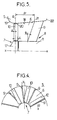
- phase modulation For a rotor with ten blades 10, an example of irregular phase or azimuth modulation is shown in FIG. 2.
- the purpose of this phase modulation is to break the usual angular symmetry or the usual angular equi-distribution of the blades.
- a rotor so as not to reduce the acoustic energy emitted, but to distribute it more favorably on the frequency spectrum, contrary to what is obtained in the absence of modulation (evenly distributed blades), namely a concentration of energy on particular frequencies (b ⁇ , 2b ⁇ , 3b ⁇ ).
- nx 360 ° b represents the angular position of the n th blade, in an evenly distributed configuration
- ⁇ ⁇ sin (mxnx 360 ° b ) corresponds to the azimuthal modulation term compared to the equi-distributed configuration.
- the parameters m and ⁇ ⁇ are chosen as a function of the number b of the blades 10, so as to simultaneously ensure the dynamic balance of the rotor 7, the optimal distribution of energy in the frequency spectrum, and guarantee an angular deviation minimum interpale, imposed by the conditions of deflection of the blades in pitch and of structural resistance of the blades 10 to the hub 17.
- the integer m is the smallest possible and preferably fixed at 2 or 3 in order to obtain the densest spectrum possible, and therefore a better energy distribution by third of octave.
- the parameter m can at most be equal to 4, but the value 1 is to be avoided.
- the minimum interpale angular spacing admissible to allow the movement of the blades 10 in steps without interference between them, as well as a suitable structural behavior of the blades 10 to the hub 17 may require a choice of ⁇ ⁇ less than ⁇ ⁇ min recommended by the acoustic criteria (table 2). For example, for a rotor 7 with ten blades 10, the minimum interpale angular spacing is 24 °.
- phase modulation law based on a degraded sinusoidal law, for which b ⁇ ⁇ can be chosen in the value range extending from 1.5 radians to 1 radians and / or adopt a variation of ⁇ 5 ° around the angular position, initially given by the sinusoidal distribution law for each blade 10 of the rotor 7, to cover the constraint of the minimum interpale angular difference, while retaining good acoustic efficiency due to the phase modulation.
- the anti-torque device comprises the rectifier 8, the vanes 9 of which are regularly distributed around the axis XX of the stream 6, in order to limit the interference between the rotor 7 and the stator rectifier 8, and in particular in order to avoid any pumping phenomenon (dynamic excitation) between the rotor 7 and the stator 8, the phase modulation of the blades 10 of the rotor 7 is such that any angular difference between two blades 10 of the rotor, not necessarily consecutive, is different from any difference angular between two vanes 9 of the stator 8, not necessarily consecutive.
- this condition can be translated as follows: if ⁇ ij represents the angular difference between the blades of order i and j of the rotor 7, counted successively from any angular origin, that is to say the angle defined between the pitch change axes of the blades i and j, and if ⁇ k, 1 represents the angular difference between the vanes of order k and 1 of the rectifier 8, then, whatever the values of i, j, k, l, ⁇ i, j is different from ⁇ k, l.
- This inclination direction not only reduces the noise of interaction between the blades 10 of the rotor 7 and the blades 9 of the stator 8, but also ensures better recovery of the forces undergone by the rear gearbox in the body 11, the vanes 9 working in compression. Indeed, one of the functions of the rectifier 8 being to support the rear gearbox and the body 11, the blades 9 can thus best take up the reaction torque to the torque transmitted to the rotor 7.
- the relative thickness aerodynamic profiles of the blades 9 of the stator 8 is chosen so as to reduce as much as possible the bulk in the vein 6, while ensuring sufficient mechanical strength for the support function of the body 11, and, in practice, the relative thickness profiles of the blades 9 is between approximately 8% and approximately 12%.
- the reduction in the interaction noise between the rotor 7 and the stator 8 becomes significant from a minimum axial spacing, between the leading edge of the vanes 9 of the stator 8 and the plane P of rotation of the rotor 7 , defined by the pitch change axes of the blades 10, at around 40% of their chord c, this minimum spacing being at least equal to 1.3 c.
- the support of the rear gearbox and of the body 11 in the vein 6 is provided by the rectifier 8, in order to ensure a good tolerance on the position of the plane P of rotation of the rotor in the vein 6, it is necessary to fix the rectifier 8, the rear gearbox and the body 11 closest possible from plane P of rotor 7.
- the axial spacing between the plane P of rotation of the rotor 7 and the leading edge of the vanes 9 of the stator 8, at the periphery of the stream 6, is a distance dr of between approximately 1.3 c and approximately 2.5 c, where c is the chord of the blades 10 of the rotor 7, chosen in their main part 14, near the foot of the blade 15, when this chord c is not constant over the span of the running part 14.
- each blade 9 is such that its edge of attack is distant from a distance dr, ranging from approximately 1.3 c to approximately 2.5 c, from the plane P of rotation of the rotor, at the periphery of the vein 6, avoiding that the trailing edge of the blades 9 penetrates into the outlet delimited by a rounded lip of this vein 6, and each blade 9 is inclined in an arrow d'un of an angle ⁇ in a plane perpendicular to the plane P of the rotor, downstream and towards the periphery of the vein 6, to ensure positioning precise of the plane P of the rotor by correct positioning of the body 11 and of the rear gearbox.
- the transmission arm 13 is assimilated to a vane 9 of the stator 8 for determining the angular positions of the vanes 9 and of the blades 10, but it is not profiled, and the number of profiled vanes 9 is chosen to be higher. or equal to the number of blades 10 of the rotor 7 minus one.
- blades 10 advantageously have an aerodynamic profile of the OAF type, with relative thickness and curvature that varies according to the span, the relative thickness decreasing for example from 13.9% to 9.5% between 0.4 R and R, where R is the radius of the rotor 7. Similarly, the twist of the profile decreases as it moves away from the axis of the rotor.
- the annular wall 18 of the vein 6 comprises, from upstream to downstream, an inlet convergent 19, a cylindrical part 20, in which the rotor 7 rotates, as indicated by the plane of rotation P, and a frustoconical diverging part 21 ending in a rounded outlet lip 22.
- the vein 6 is subdivided into two parts, including a manifold, corresponding to the part of vein located upstream of the plane of rotation P of the rotor 7, and of axial dimension dc (along the axis XX of the vein 6), and a diffuser, corresponding to the part of vein 6 located downstream of the plane of the rotor P and of axial dimension dd.
- the collector is itself divided into two zones: the convergent 19, delimited by an annular wall or convex entry lip upstream and rounded with a constant radius Rc, and a cylindrical zone of length L1 which follows it.
- the diffuser is divided into three zones, including a cylindrical zone of length L2, extending the zone cylindrical L1 of the manifold, the frustoconical zone of half-angle at the apex ⁇ of the divergent 21, and the divergent outlet delimited by the outlet lip 22, in the form of an annular wall convex downstream and rounded with radius r.
- the ratio L1 / ⁇ must be between approximately 0.02 and approximately 0.08, to avoid that a too large cylindrical zone L1 strongly degrades the performance of the rotor faired.
- the radius Rc of the inlet lip 19 is determined so that its ratio to the diameter of the vein ⁇ is approximately 0.08.
- L1 must be such that: L1> a sin ( ⁇ max) + f, where ⁇ max is the maximum positive step angle. To avoid any overflow of the blade 10 outside and at the front of the cylindrical part 20, an additional margin of 1.33% of ⁇ is taken into account.
- the length L2 of the cylindrical zone of the diffuser varies between 1% and 3.5% of the vein diameter ⁇ . In practice, it is given by the following formula: L2 ⁇ (c - a) sin ( ⁇ max).
- the angle of diffusion ⁇ (half-angle at the top of the frustoconical divergent 21) is chosen between approximately 5 ° and approximately 20 °.
- the length df of the divergent part of the diffuser depends directly on the angle of diffusion a and is inversely proportional to the diffusion, defined by a diffusion rate corresponding to the ratio of the exit surface of the vein 6 to the surface of the disc of the rotor 7, this remaining broadcast ratio greater than 1.06.
- the radius r of the convex annular lip 22 of the diffuser outlet is not constant over the entire periphery of this lip.
- the evolution zones of the radius r are shown in FIG. 7 schematically showing the outlet of the diffuser in lateral elevation.
- the YY axis is the front (to the left) - rear (to the right) or longitudinal axis of the helicopter passing through the axis XX of the vein 6, and the ZZ axis is the vertical axis also intersecting the axis XX of the vein 6.
- the lip 2 has a small constant radius r1, less than about 1.6% of the diameter ⁇ of the vein 6, in a front zone extending over the arc of circle AA corresponding to an angle at the center of 210 ° and symmetrically with respect to the YY axis.
- the lip 22 has a radius r2> r1 and between approximately 4.3% of the diameter ⁇ of the vein and the radius Rc chosen for the convergent 19, in a rear zone extending over the arc BB corresponding to an angle at the center of 90 °, symmetrically on either side of the axis YY.
- front and rear zones extend two zones with an evolving radius, between r1 and r2, and corresponding to the arcs AB each subtended by an angle at the center of 30 °.
- These zones of changing radius necessary for manufacturing constraints, ensure the transition between the front and rear parts of the output lip 22.
- the front zone of small radius r1 can extend over the arc A'A 'corresponding to an angle at the center of up to 240 °.
- the transition zones corresponding to the arcs A'B are then shorter.
- the anti-torque device is faired in a 750 mm vein 6 of diameter, with a rotor with 8 metal blades having a running tail 14 and a monobloc sleeve 15, and as described in US Pat. No.
- the diameter of the rotor hub being 304 mm
- the pitch range of the blades extending from - 25 ° to + 41 ° to 0.7 R (R is the radius of the rotor)
- the blade profile being an evolving OAF profile, as mentioned above, with a twist law decreasing from 17 ° to 6.9 ° from 0.4 R to R.
- the inclination ⁇ of the vanes 9 on the radial direction passing through the base of each is of the order of 10 ° and their angle of arrow ⁇ towards the periphery and towards the exit of the vein 6 is 4 °.
- the distance dr separating the plane of rotation P of the rotor from the leading edge of the blades 9 is 96.5 mm, or approximately 1.53 times to 1.66 times the chord of the rotor blades.
- the profiled blades 9 of the rectifier have a NACA 65 type profile with a relative thickness of 10%, a camber of the mean line of the profile of 27 ° and a pitch setting of 2.5 ° on the axis XX of the vein. 6.
- the latter has a convergent 19 whose radius Rc is 60 mm, the length L1 of the cylindrical area of the manifold is 24 mm, the length L2 of the cylindrical area of the diffuser is 23 mm, the angle of divergence ⁇ is 7 °, and the outlet lip 22 has a radius r1 of 10 mm on the front zone and a radius r2 of 45 mm on the rear zone, the minimum length of the divergent part of the diffuser df being 187 mm.
- the anti-torque device comprises a rotor with 10 blades of 50 mm of rope, driven at a peripheral speed of 187.66 m / s (3584 rpm) with a hub with a diameter of 380mm, housed in a vein of 1 m in diameter.
- the blade profile is an OAF profile similar to that of the previous example, and the pitch range extends from - 25 ° to + 35 ° (at 0.7 R).
- the rectifier has ten blades profiled with a 97 mm cord, to which is added the transmission arm 13. This leads to the following modulation: not 1 2 3 4 5 ⁇ n 44.9 ° 77.5 ° 102.5 ° 105.1 ° 180 ° not 6 7 8 9 10 ⁇ n 224.9 ° 257.5 ° 282.5 ° 315.1 ° 360 °
- the deflection angle ⁇ of the profiled blades is 4 ° and their inclination ⁇ in the radial direction is 7.8 °.
- the distance dr between the plane P of the rotor and the profiled blades 9 is approximately 98 mm, or approximately 1.96 times the chord c of the blades.
- the vanes 9 of the rectifier have a NACA 65 type profile at 10% relative thickness, with a camber of 21 ° for the middle line of the profile, and a pitch setting of 2.5 °.
- the radius Rc of the inlet converging vein 6 is 80 mm, and the lengths L1 and L2 are respectively 23 mm and 17 mm for the cylindrical areas of the manifold and the diffuser respectively.
- the angle of divergence ⁇ is 7 ° and the minimum length df of the diverging part of the vein is 280 mm.
- the radius r1 of the front zone of the lip 22 is 10 mm while its radius r2 on the rear zone is 60 mm.
- an example of anti-torque device may include a rotor of ten blades with a 94 mm rope, driven with a peripheral speed at the end of blade of 180 m / s (3125 rpm) in a vein of 1100 mm in diameter, the radius of the hub being 225 mm.
- the pitch change axis of the blades is 40% of their chord c, and their profile is an evolving OAF profile, with the same law of variation of the relative thickness, but a twist law which decreases from 7.25 ° to - 1.2 ° between 0.4 R and R.
- the straightener comprises either 13 blades, 12 of which are profiled with an 80 mm cord to which the transmission arm, i.e. 17 blades, 16 of which are profiled with a 66 mm cord and to which the transmission arm is added.
- the profile of the profiled blades is a NACA 65 type profile with 10% relative thickness, a camber of 23 ° and a pitch setting of 2.2 °.
- the angle ⁇ of tilting of the profiled blades is 3 ° and their angle ⁇ of inclination in the radial direction is 11.2 °.
- the distance dr between the plane P of the rotor and the leading edge of the blades is 1.65 c to 1.7 c, and the application of the degraded sinusoidal law mentioned above, to obtain a phase modulation leading that no angle between any two blades is equal to any angle between any two blades, leads to the angular distribution of the 10 blades of the rotor given in table 3 below (see next page), depending on whether the stator rectifier comprises 13 or 17 blades.
- FIG. 2 represents the rotor having the angular distribution indicated in table 3 above for a stator rectifier with 13 blades.
Abstract
Description
L'invention concerne des perfectionnements apportés aux dispositifs anti-couple à rotor arrière et stator redresseur carénés pour hélicoptère, dans lesquels le stator redresseur, comprenant des aubes fixes à profil aérodynamique, est fixé en aval du rotor dans la veine d'écoulement d'air ménagée transversalement dans la carène intégrée dans la structure des ensembles arrière d'un hélicoptère, tels que la poutre de queue, l'empennage ou une dérive. Les perfectionnements apportés par l'invention à des dispositifs anti-couple de ce type permettent d'améliorer leurs performances acoustiques et/ou aérodynamiques, pour procurer une réduction sensible du bruit et des nuisances acoustiques associées, ainsi qu'un meilleur contrôle en lacet, respectivement.The invention relates to improvements made to anti-torque devices with a rear rotor and streamlined stator stator for helicopters, in which the stator stator, comprising fixed blades with aerodynamic profile, is fixed downstream of the rotor in the flow stream of air arranged transversely in the hull integrated into the structure of the rear assemblies of a helicopter, such as the tail boom, the tailplane or a fin. The improvements made by the invention to anti-torque devices of this type make it possible to improve their acoustic and / or aerodynamic performance, to provide a significant reduction in noise and associated acoustic nuisances, as well as better yaw control, respectively.
On sait que l'équilibre en lacet des hélicoptères à un seul rotor principal, obtenu en contrant le couple créé par la rotation du rotor principal, peut être assuré au moyen d'un rotor anti-couple caréné dans une veine transversale dans la partie arrière de l'hélicoptère, plutôt que, de manière classique, au moyen d'un rotor de queue externe, monté latéralement sur l'empennage, à l'extrémité supérieure de ce dernier.We know that the yaw balance of helicopters with a single main rotor, obtained by countering the torque created by the rotation of the main rotor, can be ensured by means of an anti-torque rotor faired in a transverse vein in the rear part. of the helicopter, rather than, conventionally, by means of an external tail rotor, mounted laterally on the tail, at the upper end of the latter.
La structure et la disposition d'un tel rotor anti-couple caréné, de ses moyens d'entraînement en rotation, des moyens de commande collective du pas de ses pales, ainsi que les avantages d'une telle réalisation ont été présentés dans de nombreux brevets, parmi lesquels on peut citer les brevets français FR 1 531 536 et FR 2 534 222 (concernant un dispositif anti-couple à rotor et stator redresseur carénés) et les brevets américains US-3,594,097, US-4,809,931, US-4,626,172 et US-4,626,173, et le brevet américain US-5,131,604, auxquels on se reportera avantageusement pour plus de précisions à ce sujet.The structure and arrangement of such a faired anti-torque rotor, of its rotation drive means, of means for collective control of the pitch of its blades, as well as the advantages of such an embodiment have been presented in numerous Patents, among which we can cite the French patents FR 1,531,536 and FR 2,534,222 (concerning an anti-torque device with faired rotor and stator rectifier) and the American patents US-3,594,097, US-4,809,931, US-4,626,172 and US -4,626,173, and American patent US-5,131,604, to which we will advantageously refer for more details on this subject.
On se contente de rappeler que, sur le plan de la sécurité, un rotor anti-couple caréné prévient tout risque d'accident corporel au sol, du fait qu'il est protégé à l'intérieur de la veine dans la poutre de queue, contrairement à un rotor arrière classique. Cette disposition du rotor anti-couple caréné lui permet également d'éviter d'ingérer tout objet dommageable pouvant être entraîné dans le sillage du rotor principal. En vol ou en manoeuvre à proximité du sol ou sur le sol, le rotor anti-couple caréné est naturellement protégé par son carénage, ce qui prévient tout risque de choc avec des obstacles externes tels que des lignes électriques, des branches, des constructions ou même le sol, qui peuvent entraîner des dommages fatals à un rotor arrière classique, et donc la perte de l'hélicoptère, avec toutes les conséquences qui en découlent pour l'équipage. Enfin, la plus petite surface du disque rotor et le nombre de pales plus élevé d'un rotor anti-couple caréné par rapport à un rotor arrière classique rendent la vulnérabilité du premier aux impacts, tels que des projectiles militaires, beaucoup plus faible et moins critique que sur un rotor arrière classique.We are content to recall that, in terms of safety, a faired anti-torque rotor prevents any risk of bodily injury on the ground, because it is protected inside the vein in the tail boom, unlike a conventional tail rotor. This arrangement of the faired anti-torque rotor also allows it to avoid ingesting any damaging object that may be entrained in the wake of the main rotor. In flight or when maneuvering near the ground or on the ground, the faired anti-torque rotor is naturally protected by its fairing, which prevents any risk of impact with external obstacles such as power lines, branches, constructions or even the ground, which can cause fatal damage to a conventional tail rotor, and therefore the loss of the helicopter, with all the consequences that ensue for the crew. Finally, the smaller surface area of the rotor disc and the higher number of blades of a faired anti-torque rotor compared to a conventional rear rotor make the vulnerability of the former to impacts, such as military projectiles, much lower and less critical than on a conventional tail rotor.
Sur le plan aérodynamique, un rotor anti-couple caréné permet d'éliminer un certain nombre de problèmes qui se manifestent lors de l'équipement d'un hélicoptère avec un rotor arrière classique. Dans ce dernier cas, afin de créer une vitesse induite suffisante pour récupérer un niveau de poussée latérale nécessaire à la fonction anti-couple, le diamètre d'un rotor arrière classique est généralement important. Afin de minimiser les interactions avec le souffle du rotor principal et assurer une garde au sol suffisante, un rotor arrière classique est généralement monté en un point haut sur la dérive, ce qui créé un moment de roulis sur l'hélicoptère, qu'il faut équilibrer, et génère une traînée parasite en vol d'avancement à vitesse élevée. Du fait de sa position exposée, un rotor arrière classique peut être fortement sollicité par des charges dynamiques restreignant sa durée de vie. De plus, l'effet de blocage aérodynamique d'un rotor arrière classique, dû au masque de la dérive, engendre un comportement fortement dissymétrique par vent de travers, et des charges aérodynamiques périodiques impulsionnelles néfastes.On the aerodynamic level, a faired anti-torque rotor eliminates a certain number of problems which appear when equipping a helicopter with a conventional rear rotor. In the latter case, in order to create an induced speed sufficient to recover a level of lateral thrust necessary for the anti-torque function, the diameter of a conventional rear rotor is generally large. In order to minimize the interactions with the breath of the main rotor and ensure sufficient ground clearance, a conventional rear rotor is generally mounted at a high point on the fin, which creates a moment of roll on the helicopter, which must be balance, and generates parasitic drag in high speed forward flight. Due to its exposed position, a conventional tail rotor can be highly stressed by loads dynamics limiting its lifespan. In addition, the aerodynamic blocking effect of a conventional tail rotor, due to the mask of the fin, generates a strongly asymmetrical behavior in crosswinds, and harmful impulse periodic aerodynamic loads.
Un rotor arrière caréné ne présente pas ces désavantages. En général, il peut facilement être disposé de sorte que son axe coupe sensiblement l'axe de roulis de l'hélicoptère, ou soit proche de cet axe de roulis, de sorte qu'il ne créé pas de moment de roulis parasite. De plus, du fait de son carénage, il produit approximativement la moitié de sa poussée totale d'anti-couple par le seul phénomène de succion par le collecteur, à l'entrée de la veine qui le loge. Ceci permet de décharger d'autant les pales du rotor, qui ne subissent pratiquement pas de sollicitations dynamiques, en raison de la protection efficace assurée par le carénage vis-à-vis des variations externes du flux d'air, en provenance du rotor principal et du fuselage de l'hélicoptère. En vol d'avancement à vitesse élevée de ce dernier, le rotor anti-couple caréné est déchargé, ce qui diminue d'autant sa contribution à la traînée globale de l'appareil. Dans cette configuration, la dérive verticale, éventuellement équipée d'un volet braquable, assure la fonction anti-couple. De plus, aucun plan de dérive ou d'empennage ne gène le fonctionnement du rotor anti-couple caréné, ce qui lui confère une efficacité maximale par vent de travers et lors de manoeuvres rapides autour de l'axe de lacet.A faired tail rotor does not have these disadvantages. In general, it can easily be arranged so that its axis substantially intersects the roll axis of the helicopter, or is close to this roll axis, so that it does not create a parasitic roll moment. In addition, due to its fairing, it produces approximately half of its total anti-torque thrust by the sole phenomenon of suction by the collector, at the entrance to the vein that houses it. This makes it possible to discharge all the blades of the rotor, which practically do not undergo dynamic stresses, because of the effective protection provided by the fairing against external variations of the air flow, coming from the main rotor. and the fuselage of the helicopter. In forward flight at high speed of the latter, the faired anti-torque rotor is unloaded, which correspondingly reduces its contribution to the overall drag of the device. In this configuration, the vertical fin, possibly fitted with a turning flap, provides the anti-torque function. In addition, no drift or tail plane hinders the operation of the faired anti-torque rotor, which gives it maximum efficiency in crosswinds and during rapid maneuvers around the yaw axis.
L'adjonction d'un stator redresseur à aubes profilées en aval du rotor et dans la veine de carénage de ce dernier, pour récupérer l'énergie de rotation du flux d'air en aval du rotor sous forme de poussée anti-couple complémentaire et accroître ainsi la performance aérodynamique du dispositif anti-couple, comme décrit dans le brevet français FR 2 534 222, permet de renforcer l'efficacité d'un rotor arrière caréné et d'atteindre une figure de mérite largement supérieure à celle des meilleurs rotors arrière classiques.The addition of a stator stator with profiled blades downstream of the rotor and in the fairing of the latter, to recover the energy of rotation of the air flow downstream of the rotor in the form of complementary anti-torque thrust and thus increasing the aerodynamic performance of the anti-torque device, as described in
Enfin, pour une veine guidée logeant un rotor anti-couple caréné, le rapport de diffusion est voisin de 1, et peut être augmenté en augmentant l'angle de divergence d'une partie tronconique de diffuseur que la veine peut comporter en aval du plan de rotation des pales du rotor, comme décrit par exemple dans le brevet américain US-5,131,604, où cet angle de divergence est limité à 5°. Au contraire, la contraction du sillage sur un rotor arrière classique fige le rapport de diffusion à 1/2, ce qui empêche toute amélioration de performances au moyen de ce paramètre.Finally, for a guided vein housing a faired anti-torque rotor, the diffusion ratio is close to 1, and can be increased by increasing the angle of divergence of a frustoconical part of the diffuser that the vein can have downstream of the plane. of rotation of the rotor blades, as described for example in American patent US Pat. No. 5,131,604, where this angle of divergence is limited to 5 °. On the contrary, the contraction of the wake on a conventional rear rotor freezes the diffusion ratio at 1/2, which prevents any improvement in performance by means of this parameter.
Du point de vue acoustique, un rotor arrière caréné tire encore avantage de son positionnement dans une veine de carénage : au contraire d'un rotor arrière classique, qui rayonne du bruit dans toutes les directions, la détectabilité d'un rotor arrière caréné vers l'avant et vers l'arrière, dans la direction d'avancement de l'hélicoptère, est fortement réduite du fait du carénage. Par ailleurs, la combinaison d'une vitesse de rotation angulaire Ω et d'un nombre de pales b plus élevés sur un rotor anti-couple caréné que sur un rotor arrière classique produit une "fréquence de passage de pales" b x Ω et ses fréquences multiples n b Ω qui sont des fréquences beaucoup plus élevées de concentration de l'énergie acoustique que pour un rotor arrière classique, et typiquement dans le domaine des fréquences de 400 Hz à 2000 Hz. Or ces fréquences sont très vite atténuées dans l'atmosphère, alors que les très basses fréquences de concentration d'énergie acoustique d'un rotor arrière classique se propagent loin.From an acoustic point of view, a faired tail rotor still takes advantage of its positioning in a fairing vein: unlike a conventional tail rotor, which radiates noise in all directions, the detectability of a faired tail rotor towards the 'Forward and backward, in the forward direction of the helicopter, is greatly reduced due to the fairing. Furthermore, the combination of an angular speed of rotation Ω and a higher number of blades b on a faired anti-torque rotor than on a conventional tail rotor produces a "blade passage frequency" bx Ω and its frequencies multiple nb Ω which are much higher frequencies of concentration of the acoustic energy than for a traditional tail rotor, and typically in the range of frequencies from 400 Hz to 2000 Hz. However these frequencies are very quickly attenuated in the atmosphere, while the very low frequencies of acoustic energy concentration of a conventional tail rotor propagate far.
Cependant, un inconvénient des rotors anti-couple carénés est que le fait d'élever le niveau des fréquences de concentration d'énergie acoustique place ces dernières dans une zone de fréquence de maximum de sensibilité de l'oreille humaine. De plus, l'aspect très impulsif d'un spectre de bruit de rotor anti-couple caréné, pour lequel la majeure partie de l'énergie acoustique est concentrée sur les deux ou trois premières raies très étroites du spectre, se traduit par un sifflement caractéristique très pénible à l'oreille humaine, et qui est fortement pénalisé par les critères de certification acoustique au moyen des "corrections de sons purs ou raies émergentes". Au plan militaire, la signature acoustique caractéristique d'un rotor anti-couple caréné est également un phénomène préjudiciable, facilitant l'identification de l'hélicoptère.However, a drawback of faired anti-torque rotors is that raising the level of the acoustic energy concentration frequencies places the latter in a frequency zone of maximum sensitivity of the human ear. In addition, the very impulsive aspect of a faired anti-torque rotor noise spectrum, for which most of the acoustic energy is concentrated on the first two or three very narrow lines of the spectrum, is translated by a characteristic hiss very painful to the human ear, and which is strongly penalized by the criteria of acoustic certification by means of "corrections of pure sounds or emerging lines". In military terms, the acoustic signature characteristic of a faired anti-torque rotor is also a harmful phenomenon, facilitating the identification of the helicopter.
Indépendamment de la répartition de l'énergie acoustique dans le domaine de fréquences, telle que mentionnée ci-dessus, le niveau global d'énergie acoustique dissipée est le second facteur principal pour juger de la qualité du niveau acoustique d'un hélicoptère. Comme évoqué ci-dessus, et mentionné plus particulièrement dans le brevet américain US-5,131,604, le fonctionnement aérodynamique d'un rotor anti-couple caréné, à nombre de pales élevé et pour lequel la poussée anti-couple est assurée pour moitié par la succion, entraîne une charge par pale inférieure à celle subie par les pales d'un rotor arrière classique, et donc un niveau de bruit de charge inférieur.Regardless of the distribution of acoustic energy in the frequency domain, as mentioned above, the overall level of dissipated acoustic energy is the second main factor in judging the quality of the acoustic level of a helicopter. As mentioned above, and mentioned more particularly in US Pat. No. 5,131,604, the aerodynamic operation of a faired anti-torque rotor, with a high number of blades and for which the anti-torque thrust is provided for half by suction , results in a lower blade load than that experienced by the blades of a conventional tail rotor, and therefore a lower load noise level.
Par contre, la présence d'obstacles fixes dans la veine de carénage du rotor anti-couple, en aval de ce dernier, comme par exemple des bras de support d'une boîte de transmission arrière associée à un mécanisme de commande collective du pas des pales, et sur laquelle le rotor est monté en rotation, ou encore comme un stator redresseur à aubes profilées fixes, par exemple, peut fortement augmenter le niveau d'énergie acoustique rayonnée.On the other hand, the presence of fixed obstacles in the fairing of the anti-torque rotor, downstream of the latter, such as for example the support arms of a rear gearbox associated with a collective pitch control mechanism of the blades, and on which the rotor is mounted in rotation, or even as a stator rectifier with fixed profiled blades, for example, can greatly increase the level of radiated acoustic energy.
Pour cette raison, US-5,131,604 propose que les trois bras support soient de section elliptique, l'un étant radial et aligné avec l'axe longitudinal de l'hélicoptère et les deux autres parallèles à l'axe vertical du carénage, mais décalés vers l'arrière, l'écartement, selon l'axe de la veine, entre le plan de rotation du rotor et les bras support étant de 2 à 2,5 fois le petit axe de l'ellipse de la section des bras. Ces formes et dispositions permettent de diminuer sensiblement les raies d'interactions acoustiques entre le rotor et les bras support, pour un rotor à huit pales dont la vitesse périphérique est limitée à environ 225 m/s.For this reason, US Pat. No. 5,131,604 proposes that the three support arms be of elliptical section, one being radial and aligned with the longitudinal axis of the helicopter and the other two parallel to the vertical axis of the fairing, but offset towards the rear, the spacing, along the axis of the vein, between the plane of rotation of the rotor and the support arms being 2 to 2.5 times the minor axis of the ellipse of the section of the arms. These shapes and arrangements make it possible to significantly reduce the lines of acoustic interactions between the rotor and the support arms, for an eight-blade rotor whose peripheral speed is limited to approximately 225 m / s.
Par ailleurs, pour réduire l'émission sonore d'avions à hélice, il a déjà été proposé par le brevet français FR 2 622 170 que l'hélice possède un nombre de pales pair et supérieur ou égal à quatre, les pales étant diamétralement opposées deux à deux, et les paires de pales étant disposées décalées les unes par rapport aux autres avec un pas d'écart angulaire compris entre approximativement 15° et 50°, de telle sorte que les niveaux des harmoniques de bruit de rotation soient affaiblis par interférences.Furthermore, to reduce the noise emission of propeller planes, it has already been proposed by
Pour réduire l'émission sonore d'un rotor arrière caréné d'hélicoptère, il a également été proposé dans la demande de brevet européen EP 562 527 une répartition non équi-angulaire des pales du rotor. Mais, comme cette répartition non équi-angulaire peut conduire à des impossibilités structurelles de liaison des pales au moyeu du rotor, sans que les pales avec leur levier de commande de pas n'interfèrent les unes avec les autres, ce document ne propose de répartition non équi-angulaire qu'en combinaison avec le groupement des pales en deux groupes dans lesquels les leviers de commande de pas présentent des calages angulaires différents, de sorte que sur une partie de la plage de pas, la poussée anti-couple est principalement assurée par un groupe de pales, alors que sur l'autre partie de la plage de pas, elle est principalement assurée par l'autre groupe de pales, alors que les pales du premier groupe parviennent au décrochage.To reduce the noise emission of a faired tail rotor of a helicopter, it has also been proposed in European patent application EP 562 527 a non-equi-angular distribution of the rotor blades. But, as this non-equi-angular distribution can lead to structural impossibilities of connection of the blades to the hub of the rotor, without the blades with their pitch control lever interfering with each other, this document does not propose a distribution non-equi-angular that in combination with the grouping of the blades into two groups in which the pitch control levers have different angular settings, so that over part of the pitch range, the anti-torque thrust is mainly ensured by a group of blades, while on the other part of the pitch range, it is mainly provided by the other group of blades, while the blades of the first group manage to stall.
Un but de l'invention est de proposer des perfectionnements pour la réalisation d'un dispositif anti-couple à rotor et stator redresseur carénés de nuisances acoustiques minimales, destiné à équiper un hélicoptère propulsé au moyen d'un unique rotor principal, tout en conservant, voire même en améliorant, la performance aérodynamique du dispositif anti-couple caréné, par rapport aux ensembles connus de ce type.An object of the invention is to propose improvements for the production of an anti-torque device with rotor and stator rectifier streamlined with minimal noise pollution, intended to equip a helicopter propelled by means of a single main rotor, while retaining , or even by improving, the aerodynamic performance of the device fairing anti-torque, compared to known assemblies of this type.
Toujours dans le cas d'un dispositif anti-couple à rotor et stator redresseur carénés, un but de l'invention est de proposer une configuration et/ou une disposition du redresseur en fonction de la géométrie du rotor pour minimiser le bruit d'interaction, en diminuant l'énergie acoustique rayonnée.Still in the case of an anti-torque device with a faired rotor and stator rectifier, an object of the invention is to propose a configuration and / or an arrangement of the rectifier according to the geometry of the rotor to minimize the interaction noise. , by reducing the radiated acoustic energy.
Un autre but de l'invention est de proposer une configuration de veine carénée améliorant les performances aérodynamiques du dispositif anti-couple, que les pales du rotor soient ou non équi-réparties angulairement, pour augmenter le niveau de poussée à puissance donnée, et diminuer le bruit occasionné par l'écoulement d'air dans la veine.Another object of the invention is to provide a streamlined vein configuration improving the aerodynamic performance of the anti-torque device, whether or not the rotor blades are evenly distributed angularly, to increase the level of thrust at given power, and decrease the noise caused by the flow of air in the vein.
De manière générale, l'invention a pour but de proposer un dispositif anti-couple à rotor et stator redresseur carénés, qui convienne mieux aux divers exigences de la pratique que les dispositifs anti-couple carénés connus.In general, the invention aims to provide an anti-torque device with a faired rotor and stator rectifier, which is better suited to the various requirements of practice than the known faired anti-torque devices.
Les buts précités ainsi que d'autres sont atteints, selon l'invention, par un dispositif anti-couple pour hélicoptère, comprenant un rotor multipale à pas variable monté rotatif et sensiblement coaxial dans une veine d'écoulement d'air d'axe sensiblement transversal à l'hélicoptère et traversant une carène intégrée dans la partie arrière de l'hélicoptère, de sorte que les axes de changement de pas des pales se déplacent dans un plan de rotation sensiblement perpendiculaire à l'axe de la veine carénée, ainsi qu'un stator redresseur fixé dans la veine en aval du rotor et comportant des aubes fixes disposées sensiblement en étoile autour de l'axe de la veine et présentant chacune un profil aérodynamique dissymétrique dont la cambrure et le calage angulaire par rapport à l'axe de la veine sont tels que les aubes redressent le flux d'air en aval du rotor sensiblement parallèlement à l'axe de la veine, et qui se caractérise en ce que les aubes du redresseur sont chacune inclinées sur la direction radiale, de préférence d'un angle d'environ 1° à environ 25°, de l'axe de la veine vers sa périphérie, et dans le sens opposé au sens de rotation du rotor, et/ou inclinées en flèche, du centre de la veine vers sa périphérie et de l'amont vers l'aval, de préférence d'un angle d'environ 1° à environ 6° et en ce que, de plus, l'espacement, selon l'axe de la veine, entre le plan de rotation du rotor et le bord d'attaque des aubes du redresseur, à la périphérie de la veine, est une distance comprise entre 1,3 c et 2,5 c, où c est la corde des pales du rotor.The aforementioned aims as well as others are achieved, according to the invention, by an anti-torque device for a helicopter, comprising a multi-blade variable pitch rotor mounted to rotate and substantially coaxial in an air flow stream of substantially axis transverse to the helicopter and passing through a hull integrated in the rear part of the helicopter, so that the pitch change axes of the blades move in a plane of rotation substantially perpendicular to the axis of the faired vein, as well as '' a stator rectifier fixed in the vein downstream of the rotor and comprising fixed blades arranged substantially in a star around the axis of the vein and each having an asymmetrical aerodynamic profile including the camber and the angular setting relative to the axis of the vein are such that the blades straighten the air flow downstream of the rotor substantially parallel to the axis of the vein, and which characterized in that the blades of the straightener are each inclined in the radial direction, preferably from an angle of about 1 ° to about 25 °, from the axis of the vein towards its periphery, and in the opposite direction to the direction of rotation of the rotor, and / or inclined in an arrow, from the center of the vein towards its periphery and from upstream to downstream, preferably from an angle of about 1 ° to about 6 ° and in that, in addition, the spacing, along the axis of the stream, between the plane of rotation of the rotor and the leading edge of the stator vanes, at the periphery of the stream, is a distance between 1.3 c and 2.5 c, where c is the chord of the rotor blades.
Par la disposition non radiale des aubes, on évite que l'interaction du sillage d'une pale quelconque du rotor sur une aube quelconque du redresseur ne se produise simultanément sur l'ensemble de l'envergure de l'aube.By the non-radial arrangement of the blades, it is avoided that the interaction of the wake of any blade of the rotor on any blade of the stator does not occur simultaneously over the entire span of the blade.
Cette orientation est simultanément favorable à la reprise du couple, s'exerçant, en réaction à la rotation du rotor, sur un corps central sensiblement coaxial à la veine, renfermant les organes d'entraînement du rotor et les organes de commande collectives du pas des pales de ce dernier, et que les aubes du redresseur peuvent ainsi avantageusement supporter dans la veine.This orientation is simultaneously favorable to the resumption of the torque, acting, in reaction to the rotation of the rotor, on a central body substantially coaxial with the vein, enclosing the rotor drive members and the collective pitch control members of the blades of the latter, and that the blades of the stator can thus advantageously support in the vein.
L'inclinaison en flèche des aubes permet de diminuer globalement l'énergie acoustique rayonnée, les aubes étant ou non inclinées sur la direction radiale. Cette configuration, dans laquelle chaque aube de redresseur fait un angle non nul par rapport au plan de rotation des pales du rotor, en étant inclinée vers la sortie de la veine, permet d'augmenter la distance qui sépare le plan de rotation des pales de la position locale du bord d'attaque des aubes du redresseur, à la périphérie de la veine, où les aubes se raccordent à la paroi carénée de cette veine, et où la vitesse induite par le rotor dans le sillage est la plus élevée, et donc engendre une interaction plus forte sur le redresseur que vers le pied des pales. Mais le choix de cette distance (entre 1,3 c et 2,5 c) est avantageux, en particulier si la corde c est mesurée au niveau du début de la partie courante profilée de la pale, pour obtenir un bon compromis entre le niveau d'énergie acoustique rayonnée et l'efficacité aérodynamique du redresseur, et favoriser sa disposition dans la veine du dispositif anti-couple, et en particulier l'ancrage de ses aubes dans la paroi carénée de la veine, ainsi que pour assurer un bon positionnement du rotor dans la veine, par l'intermédiaire de la boîte de transmission arrière supportée dans celle-ci par les aubes.The tilted inclination of the blades makes it possible to globally reduce the radiated acoustic energy, the blades being or not inclined in the radial direction. This configuration, in which each stator vane makes a non-zero angle relative to the plane of rotation of the rotor blades, while being inclined towards the exit of the vein, makes it possible to increase the distance which separates the plane of rotation of the blades. the local position of the leading edge of the stator vanes, at the periphery of the vein, where the vanes are connected to the faired wall of this vein, and where the speed induced by the rotor in the wake is the highest, and therefore generates a stronger interaction on the rectifier than towards the base of the blades. But the choice of this distance (between 1.3 c and 2.5 c) is advantageous, in particularly if the chord c is measured at the start of the profiled running part of the blade, to obtain a good compromise between the level of radiated acoustic energy and the aerodynamic efficiency of the rectifier, and to favor its arrangement in the vein of the device anti-torque, and in particular the anchoring of its blades in the streamlined wall of the vein, as well as to ensure a good positioning of the rotor in the vein, by means of the rear gearbox supported in it by the blades.
Afin que les aubes remplissent dans de bonnes conditions simultanément leur fonction de support du corps central et leur fonction de redressement du flux d'air traversant la veine, il est avantageux qu'elles présentent un profil aérodynamique du type NACA 65, avec une épaisseur relative comprise entre environ 8 % et environ 12 %, un calage angulaire sur l'axe de la veine compris entre environ 2° et environ 2,5°, orienté à piquer, et une cambrure comprise entre environ 20° et environ 28°. L'épaisseur ainsi choisie est un compromis entre une épaisseur relative la plus faible possible, pour diminuer à la fois le bruit de charge et d'épaisseur du redresseur travaillant dans le sillage des pales en rotation, et une épaisseur suffisante pour assurer le maintien du corps supportant le rotor et renfermant la boîte de transmission arrière et la commande collective du pas des pales, qui sont ainsi solidarisés à l'ensemble arrière de l'hélicoptère, comportant l'extrémité de la poutre de queue et un empennage ou une dérive de l'hélicoptère, tout en étant soumis à des champs de forces statique et dynamique.So that the blades fulfill their good function of supporting the central body simultaneously and their function of straightening the air flow passing through the vein, it is advantageous that they have an aerodynamic profile of the NACA 65 type, with a relative thickness. comprised between approximately 8% and approximately 12%, an angular setting on the axis of the vein comprised between approximately 2 ° and approximately 2.5 °, oriented to prick, and a camber comprised between approximately 20 ° and approximately 28 °. The thickness thus chosen is a compromise between the smallest possible relative thickness, in order to reduce both the load noise and the thickness of the rectifier working in the wake of the rotating blades, and a thickness sufficient to maintain the body supporting the rotor and enclosing the rear gearbox and the collective control of the pitch of the blades, which are thus secured to the rear assembly of the helicopter, comprising the end of the tail boom and a tail or a tail fin the helicopter, while being subjected to static and dynamic force fields.
De plus, pour réduire les interférences entre le rotor et un bras de transmission, transmettant une puissance d'entraînement au rotor, et traversant la veine jusqu'à la boîte de transmission arrière, ce bras est avantageusement disposé dans la veine sensiblement à la place de l'une des aubes du redresseur, dont les aubes profilées sont avantageusement en nombre au moins égal au nombre des pales du rotor diminué d'une unité.In addition, to reduce interference between the rotor and a transmission arm, transmitting a driving power to the rotor, and crossing the vein to the rear transmission box, this arm is advantageously placed in the vein substantially in the place of one of the blades of the rectifier, the profiled blades of which are advantageously in number at least equal to the number of blades of the rotor decreased by one unit.
Selon l'invention, une diminution de la nuisance acoustique et une augmentation des performances aérodynamiques d'un dispositif anti-couple à rotor caréné peuvent également être obtenues par une configuration géométrique particulière de la veine, lorsque la modulation azimutale des pales est irrégulière ou régulière, et que le rotor est ou n'est pas associé à un redresseur.According to the invention, a reduction in the noise nuisance and an increase in the aerodynamic performance of an anti-torque device with a faired rotor can also be obtained by a particular geometrical configuration of the vein, when the azimuthal modulation of the blades is irregular or regular. , and that the rotor is or is not associated with a rectifier.
A cet effet, la veine comprend deux parties, dont l'une est un collecteur, correspondant à la partie de la veine située en amont du plan de rotation du rotor, et l'autre est un diffuseur, correspondant à la partie de la veine située en aval du plan de rotation du rotor, le collecteur comprenant un convergent d'entrée, délimité par une paroi annulaire convexe vers l'amont et arrondie avec un rayon Rc constant, et qui se prolonge vers le plan de rotation du rotor par une zone cylindrique d'une première longueur L1, et le diffuseur comprenant, du plan de rotation du rotor vers l'aval, une zone cylindrique d'une seconde longueur L2, prolongeant la zone cylindrique du collecteur, puis un divergent tronconique de demi-angle au sommet α, et une sortie divergente délimitée par une paroi annulaire convexe vers l'aval, et arrondie de rayon r.For this purpose, the vein comprises two parts, one of which is a manifold, corresponding to the part of the vein located upstream of the plane of rotation of the rotor, and the other is a diffuser, corresponding to the part of the vein. located downstream of the plane of rotation of the rotor, the manifold comprising an inlet convergent, delimited by an annular wall convex upstream and rounded with a constant radius Rc, and which extends towards the plane of rotation of the rotor by a cylindrical zone of a first length L1, and the diffuser comprising, from the plane of rotation of the rotor downstream, a cylindrical zone of a second length L2, extending the cylindrical zone of the manifold, then a frustoconical diverging of half angle at the top α, and a divergent outlet delimited by a convex annular wall downstream, and rounded with radius r.
L'existence de la partie cylindrique de veine, formée par les zones cylindriques du collecteur et du diffuseur, permet d'améliorer le fonctionnement aérodynamique de chacun des profils des pales du rotor, lorsque ce dernier est monté dans la veine de sorte que ses pales tournent à l'intérieur de cette partie cylindrique, car l'écoulement dans cette partie cylindrique est axial.The existence of the cylindrical part of the vein, formed by the cylindrical zones of the manifold and of the diffuser, makes it possible to improve the aerodynamic functioning of each of the profiles of the blades of the rotor, when the latter is mounted in the vein so that its blades rotate inside this cylindrical part, because the flow in this cylindrical part is axial.
Avantageusement, la position du plan de rotation du rotor dans cette partie cylindrique est définie en fonction de la corde c des pales du rotor, de leur plage de pas positif, de la distance a entre leur bord d'attaque et l'axe de changement de pas, et de la déformée maximale f de la pale, caractérisant sa rigidité en battement, de sorte que les longueurs L1 et L2 des zones cylindriques sont telles que : L1 > a sin (β max) + f et L2 < (c - a) sin (β max), où β max est l'angle de pas positif maximum des pales du rotor.Advantageously, the position of the plane of rotation of the rotor in this cylindrical part is defined as a function of the chord c of the blades of the rotor, of their positive pitch range, of the distance a between their leading edge and the axis of change. pitch, and the maximum deformation f of the blade, characterizing its stiffness in flapping, so that the lengths L1 and L2 of the cylindrical zones are such that: L1> a sin (β max) + f and L2 <(c - a) sin (β max), where β max is the maximum positive pitch angle of the blades of the rotor.
En pratique, il est avantageux que les longueurs L1 et L2 des zones cylindriques respectivement du collecteur et du diffuseur soient comprises respectivement entre environ 2 % et environ 8 %, et entre environ 1 % et environ 3,5 % du diamètre de la veine mesuré dans sa partie cylindrique.In practice, it is advantageous that the lengths L1 and L2 of the cylindrical zones of the collector and of the diffuser respectively are between approximately 2% and approximately 8%, and between approximately 1% and approximately 3.5% of the diameter of the measured vein. in its cylindrical part.
De même, que la veine comporte ou non une partie cylindrique, dès lors qu'elle comporte un collecteur à convergent d'entrée délimité par une paroi annulaire convexe et arrondie avec un rayon Rc constant, ce rayon est d'environ 8 % du diamètre de la veine mesuré à son col, dans sa section la plus resserrée.Likewise, whether or not the vein has a cylindrical part, as soon as it has a converging inlet manifold delimited by a convex and rounded annular wall with a constant radius Rc, this radius is approximately 8% of the diameter of the vein measured at its neck, in its tightest section.
Pour augmenter la poussée à puissance donnée, ou diminuer le bruit en diminuant la charge sur les pales du rotor, à poussée globale fixée, l'angle de diffusion du diffuseur, ou demi-angle a de son divergent tronconique, est de préférence choisi entre environ 5° et environ 20°.To increase the thrust at a given power, or decrease the noise by reducing the load on the rotor blades, at a fixed overall thrust, the diffusion angle of the diffuser, or half-angle a of its frustoconical divergent, is preferably chosen between about 5 ° and about 20 °.
Afin de réduire la traînée d'un dispositif anti-couple à rotor caréné en vol d'avancement, sans dégrader la poussée fournie par ce dispositif anti-couple, en particulier en vol stationnaire, la demanderesse a réalisé sur ses hélicoptères des modèles AS365 N1, commercialisés depuis 1985, une paroi annulaire de la sortie divergente du diffuseur ayant un premier rayon constant r1 sur un arc de cercle s'étendant vers l'avant de l'hélicoptère, un second rayon constant r2, supérieur à r1, sur un arc de cercle s'étendant vers l'arrière de l'hélicoptère, et deux zones à rayon évolutif entre r1 et r2 raccordant les zones de rayons constants, symétriquement de part et d'autre d'un axe longitudinal de l'hélicoptère. Selon l'invention, de préférence, r1 est inférieur à environ 1,6 % du diamètre de la veine, tandis que r2 est compris entre 4,3 % du diamètre de la veine et le rayon Rc choisi pour le convergent du collecteur, et la zone avant de rayon constant r1 s'étend sur un arc de cercle correspondant à un angle au centre d'au moins 210°, tandis que la zone arrière, de rayon constant r2, s'étend sur un arc de cercle correspondant à un angle au centre de 90°, symétriquement au-dessus et au-dessous de l'axe longitudinal de l'hélicoptère.In order to reduce the drag of a faired rotor anti-torque device in forward flight, without degrading the thrust provided by this anti-torque device, in particular when hovering, the applicant has produced models AS365 N1 on its helicopters , marketed since 1985, an annular wall of the divergent outlet of the diffuser having a first constant radius r1 on an arc extending towards the front of the helicopter, a second constant radius r2, greater than r1, on an arc of circle extending towards the rear of the helicopter, and two zones with an evolving radius between r1 and r2 connecting the zones of constant radii, symmetrically on either side of a longitudinal axis of the helicopter. According to the invention, preferably, r1 is less than about 1.6% of the diameter of the vein, while r2 is between 4.3% of the diameter of the vein and the radius Rc chosen for the convergent of the collector, and the front zone of constant radius r1 extends over an arc of a circle corresponding to an angle at the center of at least 210 °, while the rear zone, of constant radius r2, extends over an arc of circle corresponding to an angle at the center of 90 °, symmetrically above and below the longitudinal axis of the helicopter.
Comme dans les réalisations antérieures de dispositif anti-couple à rotor caréné, la veine peut être ménagée dans une carène intégrée dans une partie arrière d'hélicoptère comprenant l'extrémité arrière d'une poutre de queue et un empennage à au moins une dérive, l'empennage pouvant être bi-dérive et d'un type compris parmi les empennages cruciformes, en T ou en V au-dessus de la veine, et au moins une dérive de l'empennage pouvant comporter un volet de dérive braquable. De plus, l'axe de la veine peut éventuellement être incliné sur la direction horizontale de sorte que la poussée du rotor caréné produise une composante de portance sur l'hélicoptère.As in the previous embodiments of a fairing rotor anti-torque device, the vein may be formed in a hull integrated in a rear part of a helicopter comprising the rear end of a tail beam and a tailplane with at least one fin, the empennage being able to be bi-drift and of a type included among the cruciform empennage, in T or in V above the vein, and at least one stabilization of the empennage being able to comprise a deflectable flap. In addition, the axis of the vein may possibly be inclined to the horizontal direction so that the thrust of the faired rotor produces a lift component on the helicopter.
D'autres avantages et caractéristiques de l'invention découleront de la description donnée ci-dessous, à titre non limitatif, d'exemples de réalisation décrits en référence aux dessins annexés sur lesquels :
- la figure 1 est une vue en perspective de 3/4 arrière d'un dispositif anti-couple caréné, avec rotor et stator redresseur disposés dans une veine traversant une carène à l'extrémité arrière de la poutre de queue et à la base de l'empennage d'un hélicoptère, le rotor étant représenté sorti de la veine avec arrachement partiel, pour plus de clarté,
- la figure 2 est une vue schématique en élévation latérale du rotor de la figure 1 avec une modulation azimutale irrégulière des pales,
- la figure 3 est un diagramme illustrant le fonctionnement du rotor et du stator redresseur de la figure 1,
- la figure 4 est une vue partielle en élévation latérale d'un exemple particulier de réalisation du dispositif de la figure 1,
- la figure 5 correspond sensiblement à une demi-coupe axiale du dispositif anti-couple de la figure 1,
- la figure 6 représente une demi-coupe axiale de la veine des dispositifs des figures 1, 4
et 5, et - la figure 7 représente schématiquement, en élévation latérale, la sortie du diffuseur de la veine et ses parties ayant des rayons différents.
- Figure 1 is a rear 3/4 perspective view of a faired anti-torque device, with rotor and stator rectifier arranged in a vein passing through a hull at the rear end of the tail beam and at the base of the empennage of a helicopter, the rotor being shown out of the vein with partial cutaway, for greater clarity,
- FIG. 2 is a schematic side elevation view of the rotor of FIG. 1 with an irregular azimuthal modulation of the blades,
- FIG. 3 is a diagram illustrating the operation of the rotor and the stator rectifier of FIG. 1,
- Figure 4 is a partial side elevational view of a particular embodiment of the device of figure 1,
- FIG. 5 corresponds substantially to an axial half-section of the anti-torque device of FIG. 1,
- FIG. 6 represents an axial half-section of the vein of the devices of FIGS. 1, 4 and 5, and
- Figure 7 shows schematically, in side elevation, the outlet of the vein diffuser and its parts having different radii.
La poutre de queue 1, montrée sur la figure 1, d'un hélicoptère dont le fuselage et l'unique rotor principal ne sont pas représentés, supporte, à son extrémité arrière, un empennage 2, dont la partie supérieure est aménagée en dérive verticale 3, pour aider au contrôle en lacet, et, à l'avant de l'empennage 2, une dérive horizontale à deux plans 4 s'étendant de part et d'autre de la poutre 1, pour aider au contrôle en tangage de l'hélicoptère.The tail boom 1, shown in FIG. 1, of a helicopter whose fuselage and single main rotor are not shown, supports, at its rear end, a
La base de l'empennage 2 est agencée en carène 5, traversée transversalement par une veine 6 d'écoulement d'air d'un dispositif anti-couple caréné comprenant également un rotor 7 multipale à pas variable, monté rotatif et sensiblement coaxial dans la veine 6, ainsi qu'un stator redresseur 8, fixé dans la veine 6 en aval du rotor 7, par rapport au sens d'écoulement du flux d'air traversant la veine 6, et comportant des aubes fixes 9 disposées sensiblement en étoile autour de l'axe X-X de la veine 6.The base of the
Ce dispositif anti-couple, qui assure l'essentiel du contrôle en lacet en vol stationnaire ou à basse vitesse,est complété par la dérive verticale 3 et la dérive horizontale 4 pour aider au contrôle en lacet et en tangage de l'hélicoptère, en déplacement à grande vitesse. Ces mêmes fonctions peuvent être remplies par une dérive en V au-dessus de la carène 5, ou par un empennage cruciforme, la dérive 4 étant montée sensiblement à mi-hauteur sur la dérive verticale 3, ou encore à empennage en T, la dérive 4 étant montée à l'extrémité supérieure de la dérive 3.This anti-torque device, which provides most of the yaw control in hovering or at low speed, is supplemented by the vertical fin 3 and the horizontal fin 4 to help control the helicopter's yaw and pitch, in moving at high speed. These same functions can be fulfilled by a V-shaped fin above the
La veine 6 présente, autour de son axe X-X, sensiblement transversal à l'axe longitudinal de l'hélicoptère, une forme sensiblement de révolution, décrite ci-après en référence à la figure 6, et comprenant une entrée convergente 19 prolongée, vers la sortie d'air, par une partie cylindrique 20 elle-même prolongée jusqu'à la sortie par un divergent 21-22. Le rotor 7 est monté dans la veine 6 du côté de son entrée et de sorte que ses pales 10 tournent dans la partie cylindrique 20 de la veine 6, les axes de changement de pas des pales 10 définissant un plan P de rotation du rotor, dans lequel ils se déplacent et qui est sensiblement perpendiculaire à l'axe X-X de la veine carénée 6. Le rotor 7 est monté et entraîné en rotation sur la boîte de transmission arrière dans le corps central 11, de forme externe sensiblement cylindrique et coaxiale à la veine 6, et solidaire de la structure de l'empennage 2 par l'intermédiaire des aubes 9 du redresseur 8, qui maintiennent le corps 11 au centre de la veine 6 et du côté de sa sortie par rapport au rotor 7.The
De façon connue, la boîte de transmission arrière dans le corps 11 renferme un mécanisme d'entraînement en rotation du rotor 7 par un arbre moteur 12, lui-même entraîné à partir d'un arbre de transmission traversant un bras 13 et relié à une sortie annexe de la boîte de transmission principale de l'hélicoptère, une partie du bras 13 étant disposée dans la veine 6 à la place sensiblement de l'une des aubes 9 du redresseur 8.In known manner, the rear gearbox in the
Ainsi, la rotation du rotor 7 dans la veine 6 créé un écoulement d'air guidé, qui engendre la poussée transversale anti-couple nécessaire à l'équilibre en lacet de l'hélicoptère.Thus, the rotation of the
De façon également connue, pour faire varier l'amplitude de cette poussée transversale, la boîte de transmission arrière du corps 11 et le rotor 7 comprennent un dispositif de commande collective du pas des pales 10, actionné par une bielle de commande, non représentée, car on suppose que le bras 13 de la figure 1 sert de carénage à l'arbre de transmission et à la bielle de commande collective du pas.In a manner also known, to vary the amplitude of this transverse thrust, the rear gearbox of the
Pour ce qui concerne la structure, la configuration et le fonctionnement de la boîte de transmission arrière, du dispositif de commande collective du pas des pales 10, ainsi que du rotor 7, on se reportera avantageusement aux brevets français FR 1 531 536 et américains US-3,594,097 et US-4,626,173 de la demanderesse, qui sont incorporés dans le présent mémoire descriptif par voie de référence. On se limite à rappeler que chaque pale 10 comporte une partie courante 14 à profil aérodynamique, un pied de pale 15 aménagé en manchon, par lequel la pale 10 est montée tourillonnante autour de son axe longitudinal de changement de pas dans au moins un palier aménagé à cet effet dans au moins une paroi annulaire d'un moyeu de rotor 17, et une partie d'emplanture 16 torsible et de préférence également flexible, qui traverse le manchon de pied de pale 15 et est retenue par son extrémité opposée au manchon 15 sur le moyeu de rotor 17, lequel est entraîné en rotation par l'arbre moteur 12 en saillie selon l'axe X-X de la veine 6 sur le corps 11 entourant la boîte de transmission arrière. Le pied 15 de chaque pale 10 présente, en saillie d'un côté de la pale 10, un levier 23 de commande de pas, relié par une biellette à un plateau de commande tournant librement avec le rotor 7 mais translatable selon l'axe de rotation du rotor 7 par la manoeuvre de la bielle de commande de pas pour commander collectivement le changement du pas des pales 10.With regard to the structure, configuration and operation of the rear gearbox, of the collective pitch control device for the
Les aubes 9, fixées dans la veine 6 en aval des pales 10 du rotor 7, sans toutefois sortir du divergent 21-22 de la veine 6, assurent une récupération de l'énergie de rotation de l'écoulement d'air en aval des pales 10, en redressant cet écoulement vers l'axe X-X de la veine 6 et en procurant un supplément de poussée anti-couple, comme expliqué dans le brevet français FR-2 534 222 de la demanderesse, dont la description est incorporée dans le présent mémoire descriptif par voie de référence, en particulier pour ce qui concerne la description des figures 4 et 5 de ce brevet, dont la figure 5 correspond à la figure 3 de la présente demande. Sur cette figure 3, on a schématiquement représenté deux pales 10 du rotor qui tournent avec une vitesse de rotation u = Ω R, en amont de deux aubes fixes 9. Cette vitesse u se combine avec la vitesse axiale d'entrée Val de l'air pour donner une vitesse relative W1 de l'écoulement de l'air au rotor, cette dernière vitesse établissant un champ de pression autour de chaque pale mobile 10.The
Ce champ engendre alors une résultante aérodynamique R1, qui peut, d'une part, se décomposer en un effort de portance FZ1 et un effort de trainée FX1, et d'autre part, donne lieu à une poussée axiale S1 de direction orthogonale à la direction de la vitesse u de rotation du rotor, et de sens opposé à Val.This field then generates an aerodynamic result R1, which can, on the one hand, decompose into a lift force FZ1 and a drag force FX1, and on the other hand, gives rise to an axial thrust S1 in direction orthogonal to the direction of the speed u of rotation of the rotor, and opposite direction to Val.
Suite au premier obstacle constitué par chaque pale 10 considérée, l'air sort du rotor 7 dans des conditions de vitesse différentes, et le triangle des vitesses de sortie permet de distinguer une nouvelle vitesse relative W2 au rotor, inférieure à W1, et une vitesse absolue V2 qui attaque une aube fixe 9 en correspondance.Following the first obstacle constituted by each
La vitesse V2 jouant pour l'aube fixe 9 le même rôle que la vitesse W1 pour la pale mobile 10, V2 établit un champ de pression autour de chaque aube 9, et ce champ engendre une résultante aérodynamique R2, qui, d'une part, se décompose en un effort de portance FZ2 et un effort de traînée FX2, et, d'autre part, donne lieu à une poussée axiale S2, qui est une poussée additionnelle s'ajoutant à la poussée S1. En sortie des aubes 9, l'écoulement d'air est redressé et sa vitesse V3 peut être pratiquement axiale (parallèle à X-X) par le choix approprié du profil aérodynamique dissymétrique des aubes 9, et en particulier de leur cambrure et du calage angulaire par rapport à l'axe X-X de la veine 6.The speed V2 playing for the fixed
Dans un dispositif anti-couple caréné, la disposition d'un stator redresseur 8 à aubes 9 fixes profilées en aval du rotor 7 dans la veine 6 permet de réaliser un dispositif anti-couple compact, équilibré et rigide, procurant, sans modification de la puissance d'entraînement du rotor 7, une poussée anti-couple accrue.In a faired anti-torque device, the arrangement a
L'efficacité d'un tel dispositif anti-couple est ainsi liée :
- aux caractéristiques du
rotor 7, le niveau de performances requis pour assurer le pilotage en cap de l'hélicoptère dépendant en priorité du choix du diamètre durotor 7, et donc de la veine 6, de la vitesse périphérique des pales, de leur nombre, de leur corde et de leur profil et loi de vrillage, - aux caractéristiques du redresseur 8, lorsqu'il existe, et notamment du nombre des aubes 9, de leur corde, de leur profil (cambrure, calage, ...),
- ainsi qu'aux caractéristiques de la veine 6.
- to the characteristics of the
rotor 7, the level of performance required for piloting the helicopter in heading depends primarily on the choice of the diameter of therotor 7, and therefore of thevein 6, of the peripheral speed of the blades, of their number, of their rope and their profile and twist law, - to the characteristics of the
rectifier 8, when it exists, and in particular the number ofvanes 9, their chord, their profile (camber, wedging, etc.), - as well as the characteristics of the
vein 6.
Parallèlement, l'optimisation acoustique du dispositif anti-couple caréné est assurée en répartissant l'énergie acoustique sur tout le spectre de fréquence, par l'adoption d'une répartition angulaire irrégulière des pales 10 du rotor 7, appelée modulation azimutale ou modulation de phase, et en réduisant le niveau d'énergie acoustique émis par le dispositif anti-couple, par la réduction de la vitesse périphérique des pales 10 du rotor 7, par la réduction des interférences entre le rotor 7, d'une part, et, d'autre part, le stator redresseur 8 et le bras 13 de transmission, grâce à une configuration et une disposition particulières de ces éléments dans la veine 6, avec un écartement approprié du rotor 7.At the same time, the acoustic optimization of the faired anti-torque device is ensured by distributing the acoustic energy over the entire frequency spectrum, by adopting an irregular angular distribution of the
Pour un rotor à dix pales 10, un exemple de modulation de phase ou azimutale irrégulière est représenté sur la figure 2. Le but de cette modulation de phase est de rompre la symétrie angulaire habituelle ou l'équi-répartition angulaire habituelle des pales d'un rotor, afin non pas de réduire l'énergie acoustique émise, mais de la répartir plus favorablement sur le spectre de fréquence, contrairement à ce qui est obtenu en l'absence de modulation (pales équiréparties), à savoir une concentration de l'énergie sur des fréquences particulières (b Ω, 2b Ω, 3b Ω .....).For a rotor with ten
La loi de modulation de phase des pales 10 du rotor 7 est une loi sinusoïdale ou voisine d'une loi sinusoïdale de type :![]()
où Θn est la position angulaire de la n ième des pales du rotor comptées successivement à partir d'une origine angulaire quelconque, b étant le nombre des pales du rotor, et m et Δ Θ sont les paramètres de la loi sinusoïdale correspondant, pour m, à un nombre entier qui n'est pas premier avec le nombre b des pales 10 du rotor 7, tandis que Δ Θ est choisi supérieur ou égal à une valeur minimum Δ Θ min choisie en fonction du nombre de pales b, et qui diminue lorsque b augmente.The phase modulation law of the ![]()
where Θn is the angular position of the n th of the rotor blades counted successively from any angular origin, b being the number of the rotor blades, and m and Δ Θ are the parameters of the corresponding sinusoidal law, for m , to an integer which is not prime with the number b of the
On comprend que n x![]()
![]()
![]()
![]()
Le nombre entier m est choisi de la façon suivante: il est tout d'abord choisi pour respecter l'équilibre dynamique du rotor 7. En écrivant cet équilibre, on obtient les deux équations suivantes qui sont à satisfaire :![]()
![]()
Pour la loi de modulation sinusoïdale Θn donnée ci-dessus, ces deux équations sont satisfaites si m et b ne sont pas des nombres premiers entre eux.For the sinusoidal modulation law Θn given above, these two equations are satisfied if m and b are not prime numbers between them.
Les choix possibles pour m en fonction du nombre b des pales 10 variant de 6 à 12 sont donnés par des croix dans le tableau 1 ci-dessous.
En fonction des possibilités présentées dans le tableau 1, le nombre entier m est le plus petit possible et fixé de préférence à 2 ou 3 afin d'obtenir un spectre le plus dense possible, et donc une meilleure répartition d'énergie par tiers d'octave. Le paramètre m peut à la rigueur être égal à 4, mais la valeur 1 est à éviter.Depending on the possibilities presented in table 1, the integer m is the smallest possible and preferably fixed at 2 or 3 in order to obtain the densest spectrum possible, and therefore a better energy distribution by third of octave. The parameter m can at most be equal to 4, but the value 1 is to be avoided.
Le paramètre Δ Θ doit être choisi de la façon suivante : il est supérieur ou égal à une valeur minimum Δ Θ min donnée par un critère acoustique pour un nombre de pales 10 du rotor 7 donné, comme indiqué dans le tableau 2 ci-après.
Ces valeurs correspondent à un même déphasage angulaire Δ Φ = b Δ Θ, qui intervient comme paramètre des fonctions de Bessel caractérisant les niveaux des raies spectrales d'une modulation sinusoïdale, par rapport à la raie fondamentale, comme expliqué dans l'article intitulé "Noise Reduction by Applying Modulation Principles" de Donald EWALD et al, publié dans "The Journal of the Acoustical Society of America", volume 49, Number 5 (part 1) 1971, pages 1381 à 1385. Le déphasage angulaire Δ Φ = 1,5 radian correspond à la valeur à partir de laquelle la fonction de Bessel Jo (Δ Φ) est inférieure ou égale aux fonctions de Bessel Jn (Δ Φ) où n est différent de O (voir la figure 2 de l'article précité). Ceci permet de minimiser l'émergence du fondamental en b Ω vis-à-vis des raies adjacentes, car Jo (Δ Φ) représente le coefficient de pondération sur la raie fondamentale, alors que J1 (Δ Φ) représente celui des raies adjacentes (b - 1) Ω et (b + 1) Ω, qui existent s'il y a une modulation. Le déphasage angulaire Δ Φ = b Δ Θ = 1,5 radian est le point idéal, car le niveau de bruit sur les trois raies adjacentes b Ω, (b - 1) Ω et (b + 1) Ω est identique, l'énergie concentrée sur la raie b Ω pour un rotor à pales équi-réparties est ainsi répartie sur les trois raies. Le tableau 2 donne ainsi les valeurs de Δ Θ min en fonction de b, de sorte que b Δ Θ min = 1,5 radian.These values correspond to the same angular phase shift Δ Φ = b Δ Θ, which intervenes as a parameter of the Bessel functions characterizing the levels of the spectral lines of a sinusoidal modulation, relative to the fundamental line, as explained in the article entitled "Noise Reduction by Applying Modulation Principles" by Donald EWALD et al, published in "The Journal of the Acoustical Society of America", volume 49, Number 5 (part 1) 1971, pages 1381 to 1385. The angular phase shift Δ Φ = 1 , 5 radian corresponds to the value from which the Bessel function Jo (Δ Φ) is less than or equal to the Bessel functions Jn (Δ Φ) where n is different from O (see Figure 2 of the aforementioned article) . This minimizes the emergence of the fundamental in b Ω vis-à-vis the adjacent lines, because Jo (Δ Φ) represents the weighting coefficient on the fundamental line, while J1 (Δ Φ) represents that of the adjacent lines ( b - 1) Ω and (b + 1) Ω, which exist if there is a modulation. The angular phase shift Δ Φ = b Δ Θ = 1.5 radian is the ideal point, because the noise level on the three adjacent lines b Ω, (b - 1) Ω and (b + 1) Ω is identical, the energy concentrated on the line b Ω for a rotor with equi-distributed blades is thus distributed over the three lines. Table 2 thus gives the values of Δ Θ min as a function of b, so that b Δ Θ min = 1.5 radians.
Ce résultat correspond à un cas idéal, pour lequel la fonction de perturbation de pression est assez uniforme, c'est-à-dire pour un rotor avec un grand nombre de pales (supérieur à 20). Dans le cas d'un rotor anti-couple 7, le nombre relativement plus faible des pales 10 rend la fonction de perturbation de pression plus impulsive. Aussi, la règle ci-dessus peut être légèrement affectée, ce qui nécessite de définir des fourchettes de variation pour adapter la règle de modulation sinusoïdale au cas spécifique d'un rotor anti-couple caréné 7. De plus, l'écartement angulaire interpale minimal admissible pour permettre le débattement des pales 10 en pas sans interférence entre elles, ainsi qu'une tenue structurelle convenable des pales 10 au moyeu 17 peut nécessiter un choix de Δ Θ inférieur à Δ Θ min recommandé par les critères acoustiques (tableau 2). Par exemple, pour un rotor 7 à dix pales 10, l'écartement angulaire interpale minimum est de 24°.This result corresponds to an ideal case, for which the pressure disturbance function is fairly uniform, that is to say for a rotor with a large number of blades (greater than 20). In the case of an
On peut adopter alors une loi de modulation de phase basée sur une loi sinusoïdale dégradée, pour laquelle b Δ Θ peut être choisi dans la plage de valeur s'étendant de 1,5 radian à 1 radian et/ou adopter une variation de ± 5° autour de la position angulaire, donnée initialement par la loi de répartition sinusoïdale pour chaque pale 10 du rotor 7, pour couvrir la contrainte de l'écart angulaire interpale minimal, tout en conservant une bonne efficacité acoustique due à la modulation de phase.We can then adopt a phase modulation law based on a degraded sinusoidal law, for which b Δ Θ can be chosen in the value range extending from 1.5 radians to 1 radians and / or adopt a variation of ± 5 ° around the angular position, initially given by the sinusoidal distribution law for each
On note que pour b Δ Θ = 1 radian, le coefficient de pondération pour la raie fondamentale b Ω est de 0,8 et tombe à 0,45 pour les raies adjacentes (b ± 1) Ω .We note that for b Δ Θ = 1 radian, the weighting coefficient for the fundamental line b Ω is 0.8 and drops to 0.45 for the adjacent lines (b ± 1) Ω.
Lorsque le dispositif anti-couple comprend le redresseur 8, dont les aubes 9 sont régulièrement réparties autour de l'axe X-X de la veine 6, afin de limiter les interférences entre le rotor 7 et le stator redresseur 8, et en particulier afin d'éviter tout phénomène de pompage (excitation dynamique) entre le rotor 7 et le stator 8, la modulation de phase des pales 10 du rotor 7 est telle que tout écart angulaire entre deux pales 10 du rotor, non forcément consécutives, est différent de tout écart angulaire entre deux aubes 9 du stator 8, non forcément consécutives. Mathématiquement, cette condition peut se traduire de la façon suivante : si Θij représente l'écart angulaire entre les pales d'ordre i et j du rotor 7, comptées successivement à partir d'une origine angulaire quelconque, c'est-à-dire l'angle défini entre les axes de changement de pas des pales i et j, et si Θk,1 représente l'écart angulaire entre les aubes d'ordre k et 1 du redresseur 8, alors, quelles que soient les valeurs de i, j, k, l, Θi,j est différent de Θk,l. De manière pratique, cette condition est considérée respectée si les différences entre les écarts angulaires respectifs des différentes pales 10 du rotor 7 et des différentes aubes 9 du redresseur 8 sont supérieures à 1° en valeur absolue, pour au moins la moitié des aubes 9 du redresseur 8, sans tenir compte du bras de transmission 13.When the anti-torque device comprises the
Si cette condition angulaire, qui empêche deux pales 10 de passer simultanément en regard de deux aubes 9, n'est pas vérifiée par le choix de la modulation en phase de type sinusoïdale la plus avantageuse mentionnée ci-dessus, les positions angulaires de certaines pales au moins doivent être modifiées en s'écartant de la loi sinusoïdale, et en adoptant une loi sinusoïdale dégradée comme mentionnée ci-dessus, c'est-à-dire, puisqu'alors Δ Θ ne peut pas être choisi tel que b Δ Θ = 1,5 radian, qu'on diminue b Δ Θ progressivement de 1,5 vers 1 radian jusqu'à obtenir une valeur convenable de Δ Θ pour respecter la condition géométrique précitée Θi j différent de Θk l, sans descendre en dessous de 1 radian, et cumulativement ou alternativement on autorise une variation maximale de ± 5° autour de la position angulaire donnée initialement par la loi de répartition sinusoïdale de chaque pale 10 du rotor 7.If this angular condition, which prevents two
Si la diminution des nuisances sonores est recherchée en évitant les interactions simultanées entre deux pales 10 et deux aubes 9, avec un rotor 7 dont les pales 10 sont équi-réparties, il suffit de choisir un nombre b de pales 10 du rotor 7 qui soit premier avec le nombre des aubes 9 du redresseur 8, pour ne pas trouver un quelconque écart angulaire entre deux pales 10 non forcément consécutives qui soit égal à un quelconque écart angulaire entre deux aubes 9 non forcément consécutives.If the reduction in noise nuisance is sought by avoiding simultaneous interactions between two
Une diminution des nuisances acoustiques dues aux interactions entre le rotor 7 et le stator redresseur 8 est également obtenue par la diminution du niveau d'énergie acoustique émise par ces interactions, indépendamment des fréquences sur lesquelles elle est concentrée ou distribuée. Comme représenté sur la figure 4, pour éviter que l'interaction entre une pale 10 et une aube 9 ne se développe simultanément sur toute l'envergure de l'aube 9 considérée, les aubes 9 sont disposées de façon non radiale, mais inclinée chacune d'un angle ν, compris entre environ 1° et environ 25°, sur la direction radiale, dans le sens opposé au sens de rotation des pales 10 en considérant l'aube 9 du centre de la veine 6 vers sa périphérie. Cette direction de l'inclinaison permet non seulement de réduire le bruit d'interaction entre les pales 10 du rotor 7 et les aubes 9 du stator 8, mais également d'assurer une meilleure reprise des efforts subis par la boîte de transmission arrière dans le corps 11, les aubes 9 travaillant en compression. En effet, l'une des fonctions du redresseur 8 étant de supporter la boîte de transmission arrière et le corps 11, les aubes 9 peuvent ainsi reprendre au mieux le couple de réaction au couple transmis au rotor 7. De plus, l'épaisseur relative des profils aérodynamiques des aubes 9 du redresseur 8 est choisie de façon à réduire au mieux l'encombrement dans la veine 6, tout en assurant une résistance mécanique suffisante pour la fonction de support du corps 11, et, en pratique, l'épaisseur relative des profils des aubes 9 est comprise entre environ 8 % et environ 12 %.A reduction in noise pollution due to interactions between the
Ce choix de l'épaisseur relative est compatible avec l'utilisation, pour les aubes 9, d'un profil aérodynamique du type NACA 65, présentant un calage angulaire à piquer sur l'axe X-X de la veine 6 compris entre environ 2° et environ 2,5°, et une cambrure comprise entre environ 20° et environ 28°, ces caractéristiques de profil procurant une bonne efficacité au redresseur 8.This choice of the relative thickness is compatible with the use, for the
En outre, la réduction du bruit d'interaction entre le rotor 7 et le stator 8 devient significative à partir d'un écartement axial minimal, entre le bord d'attaque des aubes 9 du redresseur 8 et le plan P de rotation du rotor 7, défini par les axes de changement de pas des pales 10, à environ 40 % de leur corde c, cet écartement minimal étant au moins égal à 1,3 c. Mais comme le support de la boîte de transmission arrière et du corps 11 dans la veine 6 est assuré par le redresseur 8, afin d'assurer une bonne tolérance sur la position du plan P de rotation du rotor dans la veine 6, il est nécessaire de fixer le redresseur 8, la boîte de transmission arrière et le corps 11 le plus près possible du plan P du rotor 7.In addition, the reduction in the interaction noise between the
Un bon compromis entre ces deux exigences contradictoires, c'est-à-dire entre une réduction de bruit et une bonne tolérance sur la position du plan P du rotor 7, est obtenu en inclinant les aubes 9 du redresseur 8 d'un angle Ψ, d'environ 1° à environ 6°, comme représenté de manière exagérée sur la figure 5. Cette inclinaison de chaque aube 9 en flèche, du centre de la veine 6 vers sa périphérie et de l'amont vers l'aval, permet d'éloigner au maximum le bord d'attaque de chaque aube 9, par rapport au plan P du rotor, en préservant un positionnement correct de l'axe de la boîte de transmission arrière et du corps 11, et donc du plan P du rotor dans la veine 6. Compte tenu de l'évolution de la charge aérodynamique entre le pied de l'aube 9, lié au corps 11, et son extrémité, plus chargée, liée à la paroi latérale ou carénage 18 de la veine 6, l'influence sur le bruit reste négligeable, malgré un rapprochement du bord d'attaque des aubes 9 en arrière du pied des pales 10. Pour ces raisons, l'espacement axial, entre le plan P de rotation du rotor 7 et le bord d'attaque des aubes 9 du redresseur 8, à la périphérie de la veine 6, est une distance dr comprise entre environ 1,3 c et environ 2,5 c, où c est la corde des pales 10 du rotor 7, choisie dans leur partie courante 14, à proximité du pied de pale 15, lorsque cette corde c n'est pas constante sur l'envergure de la partie courante 14.A good compromise between these two contradictory requirements, that is to say between a noise reduction and a good tolerance on the position of the plane P of the
En résumé, en plus de l'angle ν d'inclinaison sur la direction radiale, dans un plan perpendiculaire à l'axe X-X de la veine 6, et parallèle au plan P du rotor, chaque aube 9 est telle que son bord d'attaque est éloigné d'une distance dr, allant d'environ 1,3 c à environ 2,5 c, du plan P de rotation du rotor, à la périphérie de la veine 6, en évitant que le bord de fuite des aubes 9 pénètre dans la sortie délimitée par une lèvre arrondie de cette veine 6, et chaque aube 9 est inclinée en flèche d'un angle Ψ dans un plan perpendiculaire au plan P du rotor, vers l'aval et vers la périphérie de la veine 6, pour assurer un positionnement précis du plan P du rotor par un positionnement correct du corps 11 et de la boîte de transmission arrière. Lorsque dr est inférieur à 1,3 c, le niveau d'énergie acoustique rayonnée augmente très rapidement lorsque les aubes 9 sont rapprochées du plan de rotation P, tandis que si dr est supérieur à 2,5 c, le redresseur 8 perd de son efficacité aérodynamique.In summary, in addition to the angle ν of inclination in the radial direction, in a plane perpendicular to the axis XX of the
Comme déjà dit, le bras de transmission 13 est assimilé à une aube 9 du redresseur 8 pour la détermination des positions angulaires des aubes 9 et des pales 10, mais il n'est pas profilé, et le nombre des aubes 9 profilées est choisi supérieur ou égal au nombre des pales 10 du rotor 7 moins un.As already said, the transmission arm 13 is assimilated to a
Ces pales 10 ont avantageusement un profil aérodynamique de type OAF, à épaisseur relative et cambrure évolutives selon l'envergure, l'épaisseur relative diminuant par exemple de 13,9 % à 9,5 % entre 0,4 R et R, où R est le rayon du rotor 7. De même, le vrillage du profil diminue en s'éloignant de l'axe du rotor.These
Comme montré sur la figure 6, et comme déjà décrit, la paroi annulaire 18 de la veine 6 comprend, de l'amont vers l'aval, un convergent d'entrée 19, une partie cylindrique 20, dans laquelle tourne le rotor 7, comme indiqué par le plan de rotation P, et un divergent tronconique 21 se terminant par une lèvre de sortie arrondie 22. La veine 6 se subdivise en deux parties, dont un collecteur, correspondant à la partie de veine située en amont du plan de rotation P du rotor 7, et de dimension dc axiale (selon l'axe X-X de la veine 6), et un diffuseur, correspondant à la partie de veine 6 située en aval du plan du rotor P et de dimension axiale dd. Le collecteur se divise lui-même en deux zones : le convergent 19, délimité par une paroi annulaire ou lèvre d'entrée convexe vers l'amont et arrondie avec un rayon Rc constant, et une zone cylindrique de longueur L1 qui lui fait suite. Le diffuseur se divise en trois zones, dont une zone cylindrique de longueur L2, prolongeant la zone cylindrique L1 du collecteur, la zone tronconique de demi-angle au sommet α du divergent 21, et la sortie divergente délimitée par la lèvre de sortie 22, en forme de paroi annulaire convexe vers l'aval et arrondie de rayon r.As shown in FIG. 6, and as already described, the
Si φ indique le diamètre de la veine 6 dans sa partie cylindrique 20, le rapport L1/φ doit être compris entre environ 0,02 et environ 0,08, pour éviter qu'une zone cylindrique L1 trop importante dégrade fortement les performances du rotor caréné. De même, une longueur de collecteur dc trop faible dégrade les performances du rotor caréné, de sorte que la longueur minimale du collecteur dc = Rc + L1 correspond à environ 10 % du diamètre de veine φ. Donc![]()
![]()
En pratique, le rayon Rc de la lèvre d'entrée 19 est déterminé de sorte que son rapport au diamètre de veine φ est environ de 0,08. La position du plan du rotor P dans la partie cylindrique 20 est définie en fonction de la corde c des pales 10, de leur plage de pas positif, de la distance a séparant leur bord d'attaque de leur axe de changement de pas (a = 0,4 c), et de la déformée maximale f de la pale 10, caractérisant sa rigidité en battement. L1 doit être telle que : L1 > a sin (β max) + f, où β max est l'angle de pas positif maximum. Pour éviter tout débordement de la pale 10 à l'extérieur et à l'avant de la partie cylindrique 20, on prend en compte une marge supplémentaire de 1,33 % de φ. La longueur L2 de la zone cylindrique du diffuseur évolue entre 1 % et 3,5 % du diamètre de veine φ. En pratique, elle est donnée par la formule suivante : L2 < (c - a) sin (β max).In practice, the radius Rc of the
L'angle de diffusion α (demi-angle au sommet du divergent tronconique 21) est choisi entre environ 5° et environ 20°. La longueur df de la partie divergente du diffuseur dépend directement de l'angle de diffusion a et est inversement proportionnel à la diffusion, définie par un taux de diffusion correspondant au rapport de la surface de sortie de la veine 6 à la surface du disque du rotor 7, ce rapport de diffusion restant supérieur à 1,06.The angle of diffusion α (half-angle at the top of the frustoconical divergent 21) is chosen between approximately 5 ° and approximately 20 °. The length df of the divergent part of the diffuser depends directly on the angle of diffusion a and is inversely proportional to the diffusion, defined by a diffusion rate corresponding to the ratio of the exit surface of the
Afin de réduire la traînée du dispositif anti-couple caréné en vol d'avancement de l'hélicoptère sans dégrader ses performances en vol stationnaire, le rayon r de la lèvre annulaire convexe 22 de sortie du diffuseur n'est pas constant sur toute la périphérie de cette lèvre. Les zones d'évolution du rayon r sont représentées sur la figure 7 montrant schématiquement la sortie du diffuseur en élévation latérale. Sur cette figure, l'axe Y-Y est l'axe avant (vers la gauche) - arrière (vers la droite) ou longitudinal de l'hélicoptère passant par l'axe X-X de la veine 6, et l'axe Z-Z est l'axe vertical coupant également l'axe X-X de la veine 6. La lèvre 2 a un petit rayon constant r1, inférieur à 1,6 % environ du diamètre φ de la veine 6, dans une zone avant s'étendant sur l'arc de cercle AA correspondant à un angle au centre de 210° et symétriquement par rapport à l'axe Y-Y. Afin de ne pas dégrader la poussée fournie par le dispositif anti-couple caréné, tout en réduisant la trainée en vol d'avancement, la lèvre 22 présente un rayon r2 > r1 et compris entre environ 4,3 % du diamètre φ de la veine et le rayon Rc choisi pour le convergent 19, dans une zone arrière s'étendant sur l'arc BB correspondant à un angle au centre de 90°, symétriquement de part et d'autre de l'axe YY. Entre ces zones avant et arrière s'étendent deux zones à rayon évolutif, entre r1 et r2, et correspondant aux arcs AB sous-tendus chacun par un angle au centre de 30°. Ces zones de rayon évolutif, nécessaires pour des contraintes de fabrication, assurent la transition entre les parties avant et arrière de la lèvre de sortie 22. En variante, la zone avant de petit rayon r1 peut s'étendre sur l'arc A'A' correspondant à un angle au centre pouvant atteindre 240°. Les zones de transition correspondant aux arcs A'B sont alors plus courtes.In order to reduce the drag of the faired anti-torque device in forward flight of the helicopter without degrading its hover performance, the radius r of the convex
Dans un exemple convenant à l'équipement d'un hélicoptère d'une masse de l'ordre de 1,5 tonne, le dispositif anti-couple est caréné dans une veine 6 de 750 mm de diamètre, avec un rotor à 8 pales métalliques ayant une partie courante 14 empennée et un manchon 15 monobloc, et telles que décrites dans US-3,594,097, le diamètre du moyeu rotor étant de 304 mm, la corde des pales de 58 mm ou 63 mm selon que la vitesse en bout de pale est de 186 m/s ou 180 m/s, la plage de pas des pales s'étendant de - 25° à + 41° à 0,7 R (R est le rayon du rotor), et le profil des pales étant un profil OAF évolutif, tel que précité, avec une loi de vrillage diminuant de 17° à 6,9° de 0,4 R à R.In an example suitable for equipping a helicopter with a mass of the order of 1.5 tonnes, the anti-torque device is faired in a 750
Associée à un redresseur à dix aubes 9 profilées de 80 mm de corde auxquelles s'ajoute le bras de transmission 13 [dix écarts angulaires inter-aube de 30,66° et un écart angulaire de 53,4° dans lequel passe le bras 13], le rotor à huit pales 10 présente une modulation de phase des pales selon la loi sinusoïdale optimale (b Δ Θ min = 1,5 radian) dont les paramètres sont m = 2 et Δ Θ = 10,75°, mais pour tenir compte du redresseur 8, la loi optimale est dégradée par des variations angulaires maximales de ± 3,75°, ce qui conduit à la modulation suivante des huit pales 10 du rotor 7.
Par contre, associé à un redresseur à sept aubes 9 profilées plus le bras de transmission 17, le rotor à huit pales 10 présente une modulation de phase selon une loi sinusoïdale dégradée (b Δ Θ = 1,25 radian) dont les paramètres sont m = 2 et Δ Θ = 8,96° avec des variations angulaires maximales de ± 5°, ce qui donne la modulation suivante:
L'inclinaison ν des aubes 9 sur la direction radiale passant par la base de chacune est de l'ordre de 10° et leur angle de flèche Ψ vers la périphérie et vers la sortie de la veine 6 est de 4°. La distance dr séparant le plan de rotation P du rotor du bord d'attaque des aubes 9 est de 96,5 mm, soit environ 1,53 fois à 1,66 fois la corde des pales du rotor. Les aubes profilées 9 du redresseur ont un profil de type NACA 65 avec une épaisseur relative de 10 %, une cambrure de la ligne moyenne du profil de 27° et un calage à piquer de 2,5° sur l'axe X-X de la veine 6. Cette dernière a un convergent 19 dont le rayon Rc est de 60 mm, la longueur L1 de la zone cylindrique du collecteur est de 24 mm, la longueur L2 de la zone cylindrique du diffuseur est de 23 mm, l'angle de divergence α est de 7°, et la lèvre de sortie 22 a un rayon r1 de 10 mm sur la zone avant et un rayon r2 de 45 mm sur la zone arrière, la longueur minimale de la partie divergente du diffuseur df étant de 187 mm.The inclination ν of the
Dans un exemple convenant à l'équipement d'un hélicoptère d'une masse de 2,5 tonnes environ, le dispositif anti-couple comprend un rotor de 10 pales de 50 mm de corde, entraîné à une vitesse périphérique de 187,66 m/s (3584 tr/mn) avec un moyeu d'un diamètre de 380mm, logé dans une veine de 1 m de diamètre. Le profil des pales est un profil OAF analogue à celui de l'exemple précédent, et la plage de pas s'étend de - 25° à + 35° (à 0,7 R). Les pales, qui sont de type métallique comme dans l'exemple précédent, présentent une modulation de phase ou azimutale donnée par la loi sinusoïdale précitée mais dégradée (b Δ Θ = 1 radian) dont les paramètres sont m = 2 et Δ Θ = 5,73° avec des variations angulaires maximales de ± 3,4°. Le redresseur comporte dix aubes profilées d'une corde de 97 mm, auxquelles s'ajoute le bras de transmission 13.
Ceci conduit à la modulation suivante :
This leads to the following modulation:
L'angle de flèche Ψ des aubes profilées est de 4° et leur inclinaison ν sur la direction radiale est de 7,8°. La distance dr entre le plan P du rotor et les aubes profilées 9 est d'environ 98 mm, soit environ 1,96 fois la corde c des pales. Les aubes 9 du redresseur ont un profil de type NACA 65 à 10 % d'épaisseur relative, avec une cambrure de 21° pour la ligne moyenne du profil, et un calage à piquer de 2,5°. Le rayon Rc du convergent d'entrée de la veine 6 est de 80 mm, et les longueurs L1 et L2 sont respectivement de 23 mm et 17 mm pour les zones cylindriques respectivement du collecteur et du diffuseur. L'angle de divergence α est de 7° et la longueur minimale df de la partie divergente de la veine est de 280 mm. Le rayon r1 de la zone avant de la lèvre 22 est de 10 mm tandis que son rayon r2 sur la zone arrière est de 60 mm.The deflection angle Ψ of the profiled blades is 4 ° and their inclination ν in the radial direction is 7.8 °. The distance dr between the plane P of the rotor and the profiled
Pour équiper un hélicoptère d'une masse de l'ordre de 4 à 4,5 tonnes, un exemple de dispositif anti-couple peut comprendre un rotor de dix pales d'une corde de 94 mm, entraîné avec une vitesse périphérique en bout de pale de 180 m/s (3125 tr/mn) dans une veine de 1100 mm de diamètre, le rayon du moyeu étant de 225 mm. Comme dans les exemples précédents, l'axe de changement de pas des pales est à 40 % de leur corde c, et leur profil est un profil OAF évolutif, avec la même loi de variation de l'épaisseur relative, mais une loi de vrillage qui diminue de 7,25° à - 1,2° entre 0,4 R et R. Le redresseur comprend soit 13 aubes, dont 12 profilées avec une corde de 80 mm auxquelles s'ajoute le bras de transmission, soit 17 aubes dont 16 profilées avec une corde de 66 mm et auxquelles s'ajoute le bras de transmission. Le profil des aubes profilées est un profil de type NACA 65 avec 10 % d'épaisseur relative, une cambrure de 23° et un calage à piquer de 2,2°. L'angle Ψ d'inclinaison en flèche des aubes profilées est de 3° et leur angle ν d'inclinaison sur la direction radiale est de 11,2°. La distance dr entre le plan P du rotor et le bord d'attaque des aubes est de 1,65 c à 1,7 c, et l'application de la loi sinusoïdale dégradée mentionnée ci-dessus, pour obtenir une modulation de phase conduisant à ce qu'aucun angle entre deux pales quelconques soit égal à tout angle entre deux aubes quelconques, conduit à la répartition angulaire des 10 pales du rotor donnée dans le tableau 3 ci-après (voir page suivante), selon que le stator redresseur comprend 13 ou 17 aubes.
La figure 2 représente le rotor ayant la répartition angulaire indiquée dans le tableau 3 ci-dessus pour un stator redresseur à 13 aubes.FIG. 2 represents the rotor having the angular distribution indicated in table 3 above for a stator rectifier with 13 blades.
Claims (11)
Applications Claiming Priority (2)
| Application Number | Priority Date | Filing Date | Title |
|---|---|---|---|
| FR9405479 | 1994-05-04 | ||
| FR9405479A FR2719551B1 (en) | 1994-05-04 | 1994-05-04 | Anti-torque device with faired rotor and stator rectifier and inclined rectifier vanes. |
Publications (2)
| Publication Number | Publication Date |
|---|---|
| EP0680873A1 true EP0680873A1 (en) | 1995-11-08 |
| EP0680873B1 EP0680873B1 (en) | 1998-04-01 |
Family
ID=9462872
Family Applications (1)
| Application Number | Title | Priority Date | Filing Date |
|---|---|---|---|
| EP95400998A Expired - Lifetime EP0680873B1 (en) | 1994-05-04 | 1995-05-02 | Anti-torque device with shrouded rotor and straightening stator and slanted guide vanes |
Country Status (6)
| Country | Link |
|---|---|
| US (1) | US5634611A (en) |
| EP (1) | EP0680873B1 (en) |
| JP (1) | JP3043594B2 (en) |
| CN (1) | CN1062226C (en) |
| DE (1) | DE69501911T2 (en) |
| FR (1) | FR2719551B1 (en) |
Cited By (6)
| Publication number | Priority date | Publication date | Assignee | Title |
|---|---|---|---|---|
| EP2671798A1 (en) | 2012-06-08 | 2013-12-11 | EUROCOPTER DEUTSCHLAND GmbH | Helicopter with a transverse duct |
| EP2706009A1 (en) | 2012-09-07 | 2014-03-12 | Eurocopter Deutschland GmbH | An empennage of a helicopter |
| EP2913269A1 (en) | 2014-02-28 | 2015-09-02 | AIRBUS HELICOPTERS DEUTSCHLAND GmbH | Rotorcraft with at least one main rotor and at least one counter-torque rotor |
| EP2913270A1 (en) | 2014-02-28 | 2015-09-02 | AIRBUS HELICOPTERS DEUTSCHLAND GmbH | Rotorcraft with at least one main rotor and at least one counter-torque rotor |
| EP2913271A1 (en) | 2014-02-28 | 2015-09-02 | AIRBUS HELICOPTERS DEUTSCHLAND GmbH | Rotorcraft with at least one main rotor and at least one counter-torque rotor |
| CN106837863A (en) * | 2017-03-29 | 2017-06-13 | 徐工集团工程机械有限公司 | Impeller of air conditioner, engineering truck air-conditioning and engineering truck |
Families Citing this family (26)
| Publication number | Priority date | Publication date | Assignee | Title |
|---|---|---|---|---|
| JP3051357B2 (en) * | 1997-03-26 | 2000-06-12 | 株式会社コミュータヘリコプタ先進技術研究所 | Main rotor torque correction device |
| US7234914B2 (en) * | 2002-11-12 | 2007-06-26 | Continum Dynamics, Inc. | Apparatus and method for enhancing lift produced by an airfoil |
| KR20070072850A (en) | 2004-07-16 | 2007-07-06 | 벨 헬리콥터 텍스트론, 인크. | Counter-torque device for a helicopter |
| FR2925208B1 (en) * | 2007-12-14 | 2016-07-01 | Eurocopter France | ABSORBENT STRUCTURE FOR ATTENUATING NOISE GENERATED IN PARTICULAR BY A ROTOR AND FAIRING COMPRISING SUCH A STRUCTURE |
| FR2926786B1 (en) * | 2008-01-30 | 2010-02-19 | Eurocopter France | METHOD OF OPTIMIZING A MINIMUM ACOUSTIC ACOUSTIC GENE CARENE ANTI-COUPLE ROTOR FOR A GIRAVION, IN PARTICULAR A HELICOPTER, AND CARENE ANTI-TORQUE ROTOR SO OBTAINED |
| DE102008058029B3 (en) * | 2008-11-18 | 2010-01-07 | Deutsches Zentrum für Luft- und Raumfahrt e.V. | helicopter |
| CN102712364B (en) * | 2009-05-22 | 2015-08-19 | 贝尔直升机泰克斯特龙公司 | For the rotor blade spacing of damping vibration |
| GB2482545B (en) * | 2010-08-06 | 2017-05-03 | Ge Aviat Systems Ltd | Aircraft propellers with composite blades mounted to a single propeller hub |
| US20120099983A1 (en) * | 2010-10-21 | 2012-04-26 | Charles Howard Medlock | Torque Balanced, Lift Rotor Module, Providing Increased Lift, With Few or No Moving Parts |
| US20180072408A9 (en) * | 2010-10-21 | 2018-03-15 | Charles Howard Medlock | Torque balanced, lift rotor module providing increased lift with few or no moving parts |
| FR2968272B1 (en) * | 2010-12-06 | 2013-07-12 | Eurocopter France | IMPROVED STRUCTURE ELEMENT OF A GIRAVION TO DECREASE AERODYNAMIC TRAINING. |
| FR2987346B1 (en) * | 2012-02-27 | 2014-08-29 | Eurocopter France | ROTOR BLADE, ROTOR, AIRCRAFT, AND METHOD |
| EP2799334B1 (en) * | 2013-04-29 | 2016-09-07 | AIRBUS HELICOPTERS DEUTSCHLAND GmbH | Blade rotary assembly with aerodynamic outer toroid spoiler for a shrouded propulsion rotary assembly |
| US8882024B1 (en) * | 2013-06-24 | 2014-11-11 | Bell Helicopter Textron Inc. | Rotorcraft anti-torque rotor and rudder system |
| EP2878433B1 (en) * | 2013-11-29 | 2016-04-20 | AIRBUS HELICOPTERS DEUTSCHLAND GmbH | Shrouded rotary assembly from segmented composite for aircraft and method for its manufacture |
| FR3028838B1 (en) * | 2014-11-20 | 2016-11-18 | Airbus Helicopters | AIRCRAFT WITH A ROTATING VESSEL WITH A NON-CARINE REAR ROTOR COMPRISING AT LEAST FIVE PALESTS |
| CN104648668A (en) * | 2015-02-05 | 2015-05-27 | 深圳清华大学研究院 | Tail rotor component for helicopter |
| CN104743102B (en) * | 2015-02-05 | 2017-08-25 | 深圳清华大学研究院 | Duct and duct component for helicopter |
| US9944388B2 (en) * | 2015-08-27 | 2018-04-17 | Sikorsky Aircraft Corporation | Rotorcraft state control |
| US10570926B2 (en) | 2015-12-03 | 2020-02-25 | The Boeing Company | Variable-geometry ducted fan |
| CN106477036A (en) * | 2016-11-29 | 2017-03-08 | 四川特飞科技股份有限公司 | A kind of rectangle combination duct aircraft and its flight control system and method |
| US10889366B2 (en) | 2018-09-21 | 2021-01-12 | Textron Innovations Inc. | Ducted thrusters |
| JP7269722B2 (en) * | 2018-12-13 | 2023-05-09 | 三菱重工業株式会社 | Motor-integrated fluid machine and vertical take-off and landing aircraft |
| US11034440B2 (en) | 2019-03-01 | 2021-06-15 | Textron Innovations Inc. | Tail rotor gearbox support assemblies for helicopters |
| IT201900007935A1 (en) * | 2019-06-04 | 2020-12-04 | R E M Holding S R L | FAN WITH IMPROVED FAN |
| US11566530B2 (en) * | 2019-11-26 | 2023-01-31 | General Electric Company | Turbomachine nozzle with an airfoil having a circular trailing edge |
Citations (4)
| Publication number | Priority date | Publication date | Assignee | Title |
|---|---|---|---|---|
| EP0107543A1 (en) * | 1982-10-06 | 1984-05-02 | AEROSPATIALE Société Nationale Industrielle | Increased thrust tail rotor arrangement for a rotor craft |
| GB2145774A (en) * | 1983-08-31 | 1985-04-03 | Dowty Rotol Ltd | Bladed rotors and ducts associated therewith |
| US5131604A (en) * | 1991-04-11 | 1992-07-21 | United Technologies Corporation | Helicopter antitorque device |
| EP0562527A1 (en) * | 1992-03-24 | 1993-09-29 | Kawasaki Jukogyo Kabushiki Kaisha | Tail rotor for rotor craft |
Family Cites Families (17)
| Publication number | Priority date | Publication date | Assignee | Title |
|---|---|---|---|---|
| US2962260A (en) * | 1954-12-13 | 1960-11-29 | United Aircraft Corp | Sweep back in blading |
| CH399643A (en) * | 1962-03-09 | 1965-09-30 | A De Jong N V | Ventilateur axial |
| US3270953A (en) * | 1963-05-21 | 1966-09-06 | Jerie Jan | Axial flow compressor, blower or ventilator with reduced noise production |
| US3285502A (en) * | 1965-01-25 | 1966-11-15 | Brookside Corp | Balanced fan construction |
| US3346174A (en) * | 1966-07-05 | 1967-10-10 | Trane Co | Compact axial flow fan |
| FR1531536A (en) * | 1967-05-22 | 1968-07-05 | Sud Aviation | Variable pitch propeller or rotor |
| FR1593008A (en) * | 1968-07-11 | 1970-05-25 | ||
| US3883268A (en) * | 1971-11-01 | 1975-05-13 | Gen Electric | Blunted leading edge fan blade for noise reduction |
| US3747343A (en) * | 1972-02-10 | 1973-07-24 | United Aircraft Corp | Low noise prop-fan |
| JPS5524399Y2 (en) * | 1974-09-10 | 1980-06-11 | ||
| SU726358A1 (en) * | 1978-06-29 | 1980-04-05 | Институт Горной Механики И Технической Кибернетики Им. М.М.Федорова | Axial turbomachine deflecting apparatus |
| FR2542695B1 (en) * | 1983-03-18 | 1985-07-26 | Aerospatiale | MULTI-BLADE PROPELLER WITH VARIABLE PITCH WITH BLADES IN COMPOSITE MATERIALS INDIVIDUALLY REMOVABLE, PROCESS FOR MANUFACTURING SUCH BLADES AND BLADES THUS REALIZED |
| FR2600036B1 (en) * | 1986-06-16 | 1988-09-16 | Aerospatiale | DIRECTIONAL DEVICE AND STABILIZER WITH ANTI-TORQUE HULL AND INCLINED ROTOR AND WITH A “V” DIFFERENTIAL TAKING, AND HELICOPTER EQUIPPED WITH SUCH A DEVICE. |
| DE3736141A1 (en) * | 1987-10-26 | 1989-05-11 | Deutsche Forsch Luft Raumfahrt | AIRPLANE PROPELLER |
| US5169288A (en) * | 1991-09-06 | 1992-12-08 | General Electric Company | Low noise fan assembly |
| US6070506A (en) * | 1998-07-20 | 2000-06-06 | Snap-On Tools Company | Ratchet head electronic torque wrench |
| US20040102749A1 (en) * | 2002-11-21 | 2004-05-27 | Kimberly-Clark Worldwide, Inc. | Absorbent article with low coefficient of friction between materials of differential tensions |
-
1994
- 1994-05-04 FR FR9405479A patent/FR2719551B1/en not_active Expired - Fee Related
-
1995
- 1995-04-27 JP JP7104303A patent/JP3043594B2/en not_active Expired - Fee Related
- 1995-05-02 DE DE69501911T patent/DE69501911T2/en not_active Expired - Lifetime
- 1995-05-02 EP EP95400998A patent/EP0680873B1/en not_active Expired - Lifetime
- 1995-05-03 CN CN95105363A patent/CN1062226C/en not_active Expired - Lifetime
-
1996
- 1996-09-30 US US08/720,469 patent/US5634611A/en not_active Expired - Lifetime
Patent Citations (4)
| Publication number | Priority date | Publication date | Assignee | Title |
|---|---|---|---|---|
| EP0107543A1 (en) * | 1982-10-06 | 1984-05-02 | AEROSPATIALE Société Nationale Industrielle | Increased thrust tail rotor arrangement for a rotor craft |
| GB2145774A (en) * | 1983-08-31 | 1985-04-03 | Dowty Rotol Ltd | Bladed rotors and ducts associated therewith |
| US5131604A (en) * | 1991-04-11 | 1992-07-21 | United Technologies Corporation | Helicopter antitorque device |
| EP0562527A1 (en) * | 1992-03-24 | 1993-09-29 | Kawasaki Jukogyo Kabushiki Kaisha | Tail rotor for rotor craft |
Non-Patent Citations (1)
| Title |
|---|
| VIALLE, ARNAUD: "A NEW GENERATION OF FENESTRON FAN-IN-FIN TAIL ROTOR ON EC 135", PROCEEDINGS OF THE NINETEENTH EUROPEAN ROTORCRAFT FORUM, 14 September 1993 (1993-09-14), CERNOBBIO (ITALY), pages D4-1 - D4-13 * |
Cited By (8)
| Publication number | Priority date | Publication date | Assignee | Title |
|---|---|---|---|---|
| EP2671798A1 (en) | 2012-06-08 | 2013-12-11 | EUROCOPTER DEUTSCHLAND GmbH | Helicopter with a transverse duct |
| US8967525B2 (en) | 2012-06-08 | 2015-03-03 | Airbus Helicopters Deutschland GmbH | Helicopter with a transverse duct |
| EP2706009A1 (en) | 2012-09-07 | 2014-03-12 | Eurocopter Deutschland GmbH | An empennage of a helicopter |
| US9266602B2 (en) | 2012-09-07 | 2016-02-23 | Airbus Helicopters Deutschland | Empennage of a helicopter |
| EP2913269A1 (en) | 2014-02-28 | 2015-09-02 | AIRBUS HELICOPTERS DEUTSCHLAND GmbH | Rotorcraft with at least one main rotor and at least one counter-torque rotor |
| EP2913270A1 (en) | 2014-02-28 | 2015-09-02 | AIRBUS HELICOPTERS DEUTSCHLAND GmbH | Rotorcraft with at least one main rotor and at least one counter-torque rotor |
| EP2913271A1 (en) | 2014-02-28 | 2015-09-02 | AIRBUS HELICOPTERS DEUTSCHLAND GmbH | Rotorcraft with at least one main rotor and at least one counter-torque rotor |
| CN106837863A (en) * | 2017-03-29 | 2017-06-13 | 徐工集团工程机械有限公司 | Impeller of air conditioner, engineering truck air-conditioning and engineering truck |
Also Published As
| Publication number | Publication date |
|---|---|
| CN1062226C (en) | 2001-02-21 |
| JPH08133192A (en) | 1996-05-28 |
| DE69501911T2 (en) | 1998-11-26 |
| DE69501911D1 (en) | 1998-05-07 |
| JP3043594B2 (en) | 2000-05-22 |
| CN1126159A (en) | 1996-07-10 |
| US5634611A (en) | 1997-06-03 |
| FR2719551A1 (en) | 1995-11-10 |
| FR2719551B1 (en) | 1996-07-12 |
| EP0680873B1 (en) | 1998-04-01 |
Similar Documents
| Publication | Publication Date | Title |
|---|---|---|
| EP0680872B1 (en) | Anti-torque device with shrouded rotor and straightening stator and phase modulation of the rotor blades positions, for helicopters | |
| EP0680871B1 (en) | Anti-torque device with shrouded rotor and phase modulation of the rotor blades positions for helicopters | |
| EP0680873B1 (en) | Anti-torque device with shrouded rotor and straightening stator and slanted guide vanes | |
| EP3118112B1 (en) | A compound aircraft having an additional anti-torque device | |
| EP0107543B1 (en) | Increased thrust tail rotor arrangement for a rotor craft | |
| EP0842846B1 (en) | Rotorcraft rotor blade with sweepback tip | |
| EP2799333B1 (en) | Shrouded aircraft rotor, and rotorcraft | |
| EP0901961B1 (en) | Rotorcraft rotor blade with reduced acoustic signature | |
| EP2465771B1 (en) | Blade for an anti-torque device of a helicopter | |
| EP0298826B1 (en) | Blade with bent tip for rotor craft | |
| EP2085310B1 (en) | Method of optimising a faired anti-torque rotor with minimum acoustic disturbance for a rotorcraft, in particular a helicopter, and faired anti-torque rotor thus obtained | |
| EP0036825B1 (en) | High-performance blade for helicopter rotor | |
| FR2490586A1 (en) | BLADE PROFILE FOR AN AIRCRAFT TURNING SAIL | |
| EP3184427B1 (en) | An aircraft rotor blade of shape adapted for acoustic improvement during approach flights and for improving performance in hovering flight and in forward flight | |
| EP3527491B1 (en) | Method for improving a blade in order to increase its negative stalling incidence | |
| EP3560830B1 (en) | Rotorcraft provided with a rotary wing and at least two propellers, and method applied by said rotorcraft | |
| FR2600036A1 (en) | DIRECTIONAL DEVICE AND STABILIZER WITH CARENE AND INCLINE ANTI - TORQUE ROTOR AND DISSYMETRIC V - RING, AND HELICOPTER EQUIPPED WITH SUCH A DEVICE. | |
| EP3023328A1 (en) | A rotary wing aircraft having a non-ducted tail rotor with at least five blades | |
| EP0360661A1 (en) | Rotorcraft blade and rotor using same | |
| EP3527487B1 (en) | Method of improving a blade in order to increase its negative stall incidence | |
| EP0265335B1 (en) | Propellers, in particular for aircraft propulsion units | |
| FR2793766A1 (en) | Blade for rotating wing of helicopter is divided in three zones, with width of blade maximal in first zone, decreasing linearly in second one, and decreasing following parabolic function in third one | |
| FR2898581A1 (en) | Helicopter blade for use in hub, has hollow vane end integrated to blade, where vane end is streamlined body for presenting streamlined three-dimensional shape and has lower reinforcement which locks two adjacent lower tapes | |
| FR2552395A1 (en) | IMPROVEMENTS ON LIFT PROPELLERS FOR AIRCRAFT | |
| WO2020207955A1 (en) | Rotary wing in the field of aircraft |
Legal Events
| Date | Code | Title | Description |
|---|---|---|---|
| PUAI | Public reference made under article 153(3) epc to a published international application that has entered the european phase |
Free format text: ORIGINAL CODE: 0009012 |
|
| AK | Designated contracting states |
Kind code of ref document: A1 Designated state(s): DE FR GB IT |
|
| 17P | Request for examination filed |
Effective date: 19960315 |
|
| GRAG | Despatch of communication of intention to grant |
Free format text: ORIGINAL CODE: EPIDOS AGRA |
|
| 17Q | First examination report despatched |
Effective date: 19970729 |
|
| GRAG | Despatch of communication of intention to grant |
Free format text: ORIGINAL CODE: EPIDOS AGRA |
|
| GRAG | Despatch of communication of intention to grant |
Free format text: ORIGINAL CODE: EPIDOS AGRA |
|
| GRAH | Despatch of communication of intention to grant a patent |
Free format text: ORIGINAL CODE: EPIDOS IGRA |
|
| RAP1 | Party data changed (applicant data changed or rights of an application transferred) |
Owner name: EUROCOPTER |
|
| GRAH | Despatch of communication of intention to grant a patent |
Free format text: ORIGINAL CODE: EPIDOS IGRA |
|
| GRAA | (expected) grant |
Free format text: ORIGINAL CODE: 0009210 |
|
| AK | Designated contracting states |
Kind code of ref document: B1 Designated state(s): DE FR GB IT |
|
| GBT | Gb: translation of ep patent filed (gb section 77(6)(a)/1977) |
Effective date: 19980402 |
|
| ITF | It: translation for a ep patent filed |
Owner name: BARZANO' E ZANARDO MILANO S.P.A. |
|
| REF | Corresponds to: |
Ref document number: 69501911 Country of ref document: DE Date of ref document: 19980507 |
|
| PLBE | No opposition filed within time limit |
Free format text: ORIGINAL CODE: 0009261 |
|
| STAA | Information on the status of an ep patent application or granted ep patent |
Free format text: STATUS: NO OPPOSITION FILED WITHIN TIME LIMIT |
|
| 26N | No opposition filed | ||
| REG | Reference to a national code |
Ref country code: GB Ref legal event code: IF02 |
|
| PGFP | Annual fee paid to national office [announced via postgrant information from national office to epo] |
Ref country code: DE Payment date: 20130423 Year of fee payment: 19 Ref country code: GB Payment date: 20130424 Year of fee payment: 19 |
|
| PGFP | Annual fee paid to national office [announced via postgrant information from national office to epo] |
Ref country code: FR Payment date: 20130626 Year of fee payment: 19 |
|
| PGFP | Annual fee paid to national office [announced via postgrant information from national office to epo] |
Ref country code: IT Payment date: 20140428 Year of fee payment: 20 |
|
| REG | Reference to a national code |
Ref country code: DE Ref legal event code: R119 Ref document number: 69501911 Country of ref document: DE |
|
| GBPC | Gb: european patent ceased through non-payment of renewal fee |
Effective date: 20140502 |
|
| REG | Reference to a national code |
Ref country code: DE Ref legal event code: R119 Ref document number: 69501911 Country of ref document: DE Effective date: 20141202 |
|
| REG | Reference to a national code |
Ref country code: FR Ref legal event code: ST Effective date: 20150130 |
|
| PG25 | Lapsed in a contracting state [announced via postgrant information from national office to epo] |
Ref country code: DE Free format text: LAPSE BECAUSE OF NON-PAYMENT OF DUE FEES Effective date: 20141202 |
|
| PG25 | Lapsed in a contracting state [announced via postgrant information from national office to epo] |
Ref country code: FR Free format text: LAPSE BECAUSE OF NON-PAYMENT OF DUE FEES Effective date: 20140602 Ref country code: GB Free format text: LAPSE BECAUSE OF NON-PAYMENT OF DUE FEES Effective date: 20140502 |