EP2704471B1 - Procédé d'exécution de minimisation de test de couverture radio (mdt) dans un système de communication sans fil et dispositif prenant en charge ce dernier - Google Patents
Procédé d'exécution de minimisation de test de couverture radio (mdt) dans un système de communication sans fil et dispositif prenant en charge ce dernier Download PDFInfo
- Publication number
- EP2704471B1 EP2704471B1 EP12776708.5A EP12776708A EP2704471B1 EP 2704471 B1 EP2704471 B1 EP 2704471B1 EP 12776708 A EP12776708 A EP 12776708A EP 2704471 B1 EP2704471 B1 EP 2704471B1
- Authority
- EP
- European Patent Office
- Prior art keywords
- measurement
- logging
- logged
- cell
- report
- Prior art date
- Legal status (The legal status is an assumption and is not a legal conclusion. Google has not performed a legal analysis and makes no representation as to the accuracy of the status listed.)
- Not-in-force
Links
- 238000000034 method Methods 0.000 title claims description 97
- 238000004891 communication Methods 0.000 title claims description 22
- 238000005259 measurement Methods 0.000 claims description 432
- 238000012360 testing method Methods 0.000 claims description 17
- 230000000977 initiatory effect Effects 0.000 claims 2
- 230000008569 process Effects 0.000 description 29
- 230000000875 corresponding effect Effects 0.000 description 21
- 238000010586 diagram Methods 0.000 description 18
- 230000006870 function Effects 0.000 description 18
- 230000005540 biological transmission Effects 0.000 description 10
- 238000007726 management method Methods 0.000 description 9
- 238000011156 evaluation Methods 0.000 description 7
- 230000011664 signaling Effects 0.000 description 7
- 238000012546 transfer Methods 0.000 description 7
- 238000005457 optimization Methods 0.000 description 6
- 230000004044 response Effects 0.000 description 6
- 230000008859 change Effects 0.000 description 5
- 238000010295 mobile communication Methods 0.000 description 4
- 230000001960 triggered effect Effects 0.000 description 3
- 238000005516 engineering process Methods 0.000 description 2
- 230000007774 longterm Effects 0.000 description 2
- 230000007246 mechanism Effects 0.000 description 2
- 230000002093 peripheral effect Effects 0.000 description 2
- 238000011084 recovery Methods 0.000 description 2
- 230000002123 temporal effect Effects 0.000 description 2
- 241000700159 Rattus Species 0.000 description 1
- 238000004458 analytical method Methods 0.000 description 1
- 230000006399 behavior Effects 0.000 description 1
- 230000003915 cell function Effects 0.000 description 1
- 230000006835 compression Effects 0.000 description 1
- 238000007906 compression Methods 0.000 description 1
- 238000012937 correction Methods 0.000 description 1
- 230000002596 correlated effect Effects 0.000 description 1
- 230000003111 delayed effect Effects 0.000 description 1
- 230000006866 deterioration Effects 0.000 description 1
- 230000000694 effects Effects 0.000 description 1
- 238000012854 evaluation process Methods 0.000 description 1
- 238000001914 filtration Methods 0.000 description 1
- 230000006872 improvement Effects 0.000 description 1
- 238000012423 maintenance Methods 0.000 description 1
- 238000013507 mapping Methods 0.000 description 1
- 238000000691 measurement method Methods 0.000 description 1
- 238000012545 processing Methods 0.000 description 1
- 230000001105 regulatory effect Effects 0.000 description 1
- 238000013468 resource allocation Methods 0.000 description 1
- 230000011218 segmentation Effects 0.000 description 1
- 238000010187 selection method Methods 0.000 description 1
- 230000008054 signal transmission Effects 0.000 description 1
- 230000002194 synthesizing effect Effects 0.000 description 1
Images


Classifications
-
- H—ELECTRICITY
- H04—ELECTRIC COMMUNICATION TECHNIQUE
- H04W—WIRELESS COMMUNICATION NETWORKS
- H04W24/00—Supervisory, monitoring or testing arrangements
- H04W24/08—Testing, supervising or monitoring using real traffic
-
- H—ELECTRICITY
- H04—ELECTRIC COMMUNICATION TECHNIQUE
- H04W—WIRELESS COMMUNICATION NETWORKS
- H04W24/00—Supervisory, monitoring or testing arrangements
- H04W24/10—Scheduling measurement reports ; Arrangements for measurement reports
Definitions
- the present invention relates to a wireless communication system and, more particularly, to a method of performing a Minimization Drive Test (MDT) based on time-related measurement configuration information in a wireless communication system.
- MDT Minimization Drive Test
- 3GPP LTE Long Term Evolution
- UMTS Universal Mobile Telecommunications System
- 3GPP LTE uses Orthogonal Frequency Division Multiple Access (OFDMA) in downlink and uses Single Carrier-Frequency Division Multiple Access (SC-FDMA) in uplink.
- 3GPP LTE adopts Multiple Input Multiple Output (MIMO) having a maximum of 4 antennas.
- 3GPP LTE-Advanced (LTE-A) that is, the evolution of 3GPP LTE, is being discussed.
- a Minimization Drive Test is that service providers perform a test using UE instead of a vehicle for coverage optimization. Coverage varies depending on the location of a BS, the deployment of peripheral buildings, and a user use environment. Accordingly, a service provider needs to periodically perform a driving test, and lots of costs and resources are consumed.
- An MDT is that a service provider measures coverage using UE.
- An MDT can be divided into a logged MDT and an immediate MDT.
- UE performs MDT measurement and then transfers logged measurement to a network at a specific point of time.
- UE performs MDT measurement and then transfers measurement to a network when a report condition is satisfied.
- MDT measurement is performed in an RRC idle mode
- MDT measurement is performed in an RRC connected mode.
- the usage of a wireless network can be suddenly increased at a specific time.
- log the radio environments or UE capability criteria can be preferred.
- UE reports a logged measurement result to a network during the time when the usage of a wireless network is suddenly increased a problem in which the congestion of a wireless communication network is further increased can occur.
- Suitability in executing logging and/or a report by UE can vary in each time interval as described above.
- EP 2 437 540 discloses a Minimizing Drive Test (MDT) logging measurement method and device.
- the method includes: generating MDT logging measurement configuration information, and sending the MDT logging measurement configuration information to an active User Equipment (UE) and/or an idle UE according to a predetermined rule.
- UE User Equipment
- a commercial UE in an existing network may be utilized to assist in locating a network problem, thus reducing a Drive Test (DT) overhead.
- DT Drive Test
- 3rd Generation Partnership Project; Technical Specification Group Radio Access Network Universal Terrestrial Radio Access (TTRA) and Evolved Universal Terrestrial Radio Access (E-UTRA); Radionmeasurement collection for Minimization of Drive Tests (MDT); Overall description; Stage 2 (Release 10) 3GPP TS 37.320 V10.0.0 " discloses an overview and description of the minimization of drive tests functionality.
- the document describes functions and procedures to support autonomous collection of UE measurements using Control Plane architecture for both UTRAN and E-UTRAN. Details of the signaling procedures for single-Rat operation are specified in the appropriate radio interface protocol specification.
- MDT configuration for logging in idle mode discusses MDT measurement configurations for logged reporting in idle mode. Reference is also described in 3GPP TS 36.331 V10.10. Accordingly, there is a need for a method in which UE performs an MDT or reports radio link failure information suitably for a wireless communication network situation.
- An object of the present invention is to provide a method of performing a Minimization Drive Test (MDT) based on time-related measurement configuration information in a wireless communication system.
- MDT Minimization Drive Test
- a method of performing, by user equipment (UE), a Minimization Drive Test (MDT) in a wireless communication system includes receiving a logged measurement configuration, performing MDT measurement and logging a measurement result based on the logged measurement configuration, and reporting all or part of the logged measurement result to a network.
- the logged measurement configuration comprises logging end time information indicating that the MDT measurement and the measurement result logging are ended. The steps of performing the MDT measurement and logging the measurement result are performed until the time indicated by the logging end time information.
- the method may further include discarding the logged measurement configuration when the end time indicated by the logging end time information elapses.
- the logged measurement configuration may further include logging start time information indicative of a start time when performing the MDT measurement and logging the measurement result are allowed.
- the steps of performing the MDT measurement and logging the measurement result may be performed when the start time indicated by the logging start time information is reached and until the end time indicated by the logging end time information.
- the logged measurement configuration may include logging interval information, the logging interval information indicates a specific time interval.
- the step of performing the MDT measurement and logging the measurement result may be periodically performed in accordance with the specific time interval.
- the UE may be in a Radio Resource Control (RRC) idle state at a point of time at which the MDT measurement is performed and the measurement result is logged.
- RRC Radio Resource Control
- the logged measurement configuration may further include log report end time information.
- the log report end time information may indicate an end time when the report is ended.
- the method may further include discarding remaining logged measurement result if the end time indicated by the log report end time information elapses and the remaining logged measurement result not reported is present in the logged measurement result.
- the logged measurement configuration may further include log report start time information.
- the log report start time information may indicate a start time when the report is allowed.
- the report may be performed when the start time indicated by the log report start time is reached and until the end time indicated by the log report end time.
- the UE may be in an RRC_connected state.
- a wireless apparatus in another aspect, includes a Radio Frequency (RF) unit transmitting and receiving radio signals, and a processor operably coupled to the RF unit.
- the processor is configured to receive a logged measurement configuration, perform a Minimization Driving Test (MDT) measurement and log a measurement result based on the logged measurement configuration, and report all or a part of the logged measurement result to a network.
- the logged measurement configuration comprises logging end time information indicating that the MDT measurement and the measurement result logging are ended The performing the MDT measurement and the logging the measurement result are performed until the time indicated by the logging end time information.
- the processor may be configured to discard the logged measurement configuration when the end time indicated by the logging end time information elapses.
- the logged measurement configuration may further include logging start time information indicative of a start time when performing the MDT measurement and logging the measurement result are allowed.
- the performing the MDT measurement and the logging the measurement result may be performed when the start time indicated by the logging start time information is reached and until the end time indicated by the logging end time information.
- the wireless apparatus may be in a Radio Resource Control (RRC) idle state at a point of time at which the MDT measurement is performed and the measurement result is logged.
- RRC Radio Resource Control
- the logged measurement configuration may further include log report end time information.
- the log report end time information may indicate an end time when the report is ended.
- the processor may be further configured to discard remaining logged measurement result if the end time indicated by the log report end time information elapses and the remaining logged measurement result not reported is present in the logged measurement result.
- the logged measurement configuration may further include log report start time information.
- the log report start time information may indicate a start time when the report is allowed.
- the report may be performed when the start time indicated by the log report start time is reached and until the end time indicated by the log report end time.
- the UE may be in an RRC_connected state.
- UE can generate logging or radio link failure information for a specific time interval and report logged measurement and the generated radio link failure information to a network for a specific time interval. Accordingly, a network can obtain a logged measurement result more efficiently because UE intensively performs logging at a necessary time. Or, a network can efficiently obtain corresponding information because UE detects a radio link failure and generates and reports radio link failure information at a necessary time. UE reports logged measurement or generated radio link failure information to a network within a specific time interval, so-called within a time zone in which occurrence frequency of traffic is low. Accordingly, a loss of information due to a lapse of time can be prevented from occurring.
- a network can implement the optimization of a wireless communication system more effectively based on information obtained as described above.
- FIG. 1 shows a wireless communication system to which the present invention is applied.
- the wireless communication system may also be called an Evolved-UMTS Terrestrial Radio Access Network (E-UTRAN) or a Long Term Evolution (LTE)/LTE-A system.
- E-UTRAN Evolved-UMTS Terrestrial Radio Access Network
- LTE Long Term Evolution
- LTE-A Long Term Evolution
- the E-UTRAN includes a Base Station (BS) 20 which provides User Equipment (UE) 10 with a control plane and a user plane.
- the UE 10 may be fixed or may have mobility.
- the UE 10 may be called another term, such as a Mobile Station (MS), a User Terminal (UT), a Subscriber Station (SS), a Mobile Terminal (MT), or a wireless device.
- the BS 20 refers to a fixed station communicating with the UE 10 and may be called another term, such as an evolved-NodeB (eNB), a Base Transceiver System (BTS), or an access point.
- eNB evolved-NodeB
- BTS Base Transceiver System
- the BSs 20 may be interconnected through an X2 interface.
- the BS 20 is connected to an Evolved Packet Core (EPC) 30 through an S1 interface, more particularly, to a Mobility Management Entity (MME) through an S1-MME and a Serving Gateway (S-GW) through an S1-U.
- EPC Evolved Packet Core
- MME Mobility Management Entity
- S-GW Serving Gateway
- the EPC 30 includes the MME, the S-GW, and a Packet Data Network-Gateway (P-GW).
- the MME has access information about UE or information about the capabilities of UE. Such information is chiefly used in the mobility management of UE.
- the S-GW is a gateway having an E-UTRAN as an end point
- the P-GW is a gateway having a PDN as an end point.
- the layers of a radio interface protocol between UE and a network may be classified into L1 (first layer), L2 (second layer), and L3 (third layer) based on lower 3 layers of an Open System Interconnection (OSI) reference model which is widely known in communication systems.
- OSI Open System Interconnection
- the PHY layer belonging to the first layer provides information transfer service using physical channels, and a Radio Resource Control (RRC) layer placed in the third layer functions to control radio resources between UE and a network.
- RRC Radio Resource Control
- the RRC layer exchanges RRC messages between UE and a BS.
- FIG. 2 is a block diagram showing a radio protocol architecture for a user plane.
- FIG. 3 is a block diagram showing a radio protocol architecture for a control plane.
- a data plane is a protocol stack for user data transmission
- a control plane is a protocol stack for control signal transmission.
- a physical (PHY) layer provides a higher layer with information transfer service using physical channels.
- the PHY layer is connected to a Medium Access Control (MAC) layer, that is, a higher layer, through a transport channel. Data is moved between the MAC layer and the PHY layer through the transport channel.
- the transport channel is classified depending on how data is transmitted through a radio interface according to what characteristics.
- the physical channel may be modulated according to an Orthogonal Frequency Division Multiplexing (OFDM) scheme, and the physical channel uses the time and frequency as radio resources.
- OFDM Orthogonal Frequency Division Multiplexing
- the functions of the MAC layer include mapping between a logical channel and a transport channel and multiplexing/de-multiplexing to a transport block that is provided to a physical channel on the transport channel of an MAC Service Data Unit (SDU) that belongs to a logical channel.
- SDU MAC Service Data Unit
- the MAC layer provides service to a Radio Link Control (RLC) layer through a logical channel.
- RLC Radio Link Control
- the functions of the RLC layer include the concatenation, segmentation, and reassembly of an RLC SDU.
- QoS Quality of Service
- RB Radio Bearer
- the RLC layer provides three operation modes: a Transparent Mode (TM), an Unacknowledged Mode (UM), and an Acknowledged Mode (AM).
- TM Transparent Mode
- UM Unacknowledged Mode
- AM Acknowledged Mode
- AM RLC provides error correction through an Automatic Repeat Request (ARQ).
- ARQ Automatic Repeat Request
- PDCP Packet Data Convergence Protocol
- the functions of a Packet Data Convergence Protocol (PDCP) layer in the user plane include the transfer, header compression, and ciphering of user data.
- the functions of the PDCP layer in the user plane include the transfer and ciphering/integrity protection of control plane data.
- the Radio Resource Control (RRC) layer is defined only in the control plane.
- the RRC layer is related to the configuration, re-configuration, and release of RBs and responsible for control of logical channels, transport channels, and physical channels.
- An RB means a logical path that is provided by the first layer (PHY layer) and the second layers (the MAC layer, the RLC layer, and the PDCP layer) for the transfer of data between UE and a network.
- What an RB is configured means a process of regulating the characteristics of a radio protocol layer and channel and configuring each detailed parameter and operation method in order to provide specific service.
- An RB may be divided into a Signaling RB (SRB) and a Data RB (DRB).
- SRB Signaling RB
- DRB Data RB
- the SRB is used as a passage along which an RRC message is transported in the control plane
- the DRB is used as a passage along which user data is transported in the user plane.
- the UE If an RRC connection is established between the RRC layer of UE and the RRC layer of an E-UTRAN, the UE is in an RRC connected state. If not, the UE is in the RRC_idle state.
- a downlink transport channel through which data is transmitted from a network to UE includes a broadcast channel (BCH) through which system information is transmitted and a downlink shared channel (SCH) through which user traffic or control messages are transmitted.
- Traffic or a control message for downlink multicast or broadcast service may be transmitted through a downlink SCH or may be transmitted through an additional downlink multicast channel (MCH).
- an uplink transport channel through which data is transmitted from UE to a network includes a random access channel (RACH) through which an initial control message is transmitted and an uplink shared channel (SCH) through which user traffic or a control message is transmitted.
- RACH random access channel
- SCH uplink shared channel
- Logical channels placed over a transport channel and mapped to the transport channel include a broadcast control channel (BCCH), a paging control channel (PCCH), a common control channel (CCCH), a multicast control channel (MCCH), a multicast traffic channel (MTCH), and so on.
- BCCH broadcast control channel
- PCCH paging control channel
- CCCH common control channel
- MCCH multicast control channel
- MTCH multicast traffic channel
- a physical channel includes several OFDM symbols in a time domain and several subcarriers in a frequency domain.
- One subframe consists of a plurality of OFDM symbols in the time domain.
- a resource block is a resource allocation unit, and a resource block consists of a plurality of OFDM symbols and a plurality of subcarriers.
- each subframe may use specific subcarriers of specific OFDM symbols (e.g., the first OFDM symbol) of a corresponding subframe for a physical downlink control channel (PDCCH), that is, an L1/L2 control channel.
- PDCCH physical downlink control channel
- a Transmission Time Interval (TTI) is a unit time for subframe transmission.
- An RRC state means whether or not the RRC layer of UE has been logically connected with the RRC layer of an E-UTRAN. If the RRC layer of UE is logically connection with the RRC layer of an E-UTRAN, it is called the RRC_connected state. If the RRC layer of UE is not logically connection with the RRC layer of an E-UTRAN, it is called the RRC_idle state. Since UE in the RRC connected state has an RRC connection, an E-UTRAN may check the presence of the UE in a cell unit, and thus the UE may be effectively controlled.
- an E-UTRAN cannot check UE in the RRC_idle state, and UE in the RRC_idle state is managed by a Core Network (CN) in a tracking area, that is, an area unit greater than a cell. That is, the presence of UE in the RRC_idle state is checked in a larger area unit, and the UE in the RRC_idle state needs to move to the RRC_connected state in order to receive common mobile communication service, such as voice or data.
- CN Core Network
- the UE When a user first powers on UE, the UE first searches for a suitable cell and remains in the RRC_idle state in a corresponding cell.
- UE in the RRC_idle state establishes an RRC connection with an E-UTRAN through an RRC connection procedure when it needs to establish the RRC connection and shifts to the RRC _connected state.
- a case where the UE in the RRC_idle state needs to establish the RRC connection includes several cases. For example, the UE in the RRC_idle state establishes an RRC connection when it needs to send uplink data for a reason, such as a call attempt by a user, or when it sends a message in response to a paging message received from an E-UTRAN.
- a Non-Access Stratum (NAS) layer placed over the RRC layer performs functions, such as session management and mobility management.
- functions such as session management and mobility management.
- EMM-REGISTERED EPS Mobility Management-REGISTERED
- EMM-DEREGISTERED EMM-DEREGISTERED
- the two states are applied to UE and an MME.
- Initial UE is in the EMM-DEREGISTERED state.
- the UE performs a process of being registered with the network through an initial attach procedure. If the attach procedure is successfully performed, the UE and the MME become the EMM-REGISTERED state.
- an EPS Connection Management (ECM)-IDLE state In order to manage signaling connection between UE and an EPC, two states: an EPS Connection Management (ECM)-IDLE state and an ECM-CONNECTED state are defined.
- the two states are applied to UE and an MME. If UE in the ECM-IDLE state establishes an RRC connection with an E-UTRAN, the UE becomes the ECM-CONNECTED state. If an MME in the ECM-IDLE state establishes an S1 connection with the E-UTRAN, the MME becomes the ECM-CONNECTED state.
- ECM-IDLE state an ECM-CONNECTED state.
- the UE in the ECM-IDLE state performs a mobility-based procedure based UE, such as cell selection or cell reselection, without a need to receive a command from a network.
- a mobility-based procedure based UE such as cell selection or cell reselection
- the mobility of the UE is managed by a command from a network. If the location of UE is different from a location known to a network in the ECM-IDLE state, the UE informs the network of the location of the UE through a tracking area update procedure.
- System information includes essential information that needs to be known by UE in order to access a BS. Accordingly, the UE needs to have received all pieces of system information before accessing the BS and needs to always have recent system information. Furthermore, system information is information that needs to be known by all pieces of UE within one cell, and thus a BS periodically transmits the system information.
- system information is classified into a Master Information Block (MIB), a Scheduling Block (SB), and a System Information Block (SIB).
- MIB Master Information Block
- SB Scheduling Block
- SIB System Information Block
- the MIB enables UE to know the physical configuration of a corresponding cell, for example, a bandwidth.
- the SB informs information about the transmission of SIBs, for example, a transport period.
- the SIB is a collection of pieces of correlated system information. For example, any SIB includes only information about neighboring cells, and any SIB includes only information about an uplink radio channel used by UE.
- service provided from a network to UE may be classified into three types as follows. Furthermore, UE differently recognizes the type of cell depending on what service may be received. A service type is first described, and the type of cell is then described.
- the type of cell can be classified as follows.
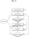
- FIG. 4 is a flowchart illustrating the operation of UE in the RRC_idle state.
- FIG. 4 shows a procedure in which UE that is initially powered on is registered with a network through a cell selection process and the UE performs cell reselection, if necessary.
- the UE selects Radio Access Technology (RAT) for communicating with a Public Land Mobile Network (PLMN), that is, a network from which the UE is provided with service (S410).
- RAT Radio Access Technology
- PLMN Public Land Mobile Network
- S410 a network from which the UE is provided with service
- Information about the PLMN and the RAT may be selected by the user of the UE, and information stored in a Universal Subscriber Identity Module (USIM) may be used.
- USIM Universal Subscriber Identity Module
- the UE selects a cell having the greatest value from cells whose measured BS and signal intensity or quality is greater than a specific value (S420).
- a specific value S420
- powered-on UE performs cell selection, which may be called initial cell selection. Cell selection procedure is described in detail later.
- the UE receives system information that is periodically transmitted by a BS.
- the specific value refers to a value defined in a system in order to guarantee quality for a physical signal in data transmission/reception. Accordingly, the value may be different depending on applied RAT.
- the UE performs a network registration procedure (S430).
- the UE registers its own information (e.g., IMSI) with the network in order to receive service (e.g., paging) from the network.
- the UE does not register its information with an accessing network whenever the UE selects a cell, but registers its information with a network if information (e.g., Tracking Area Identity (TAI)) about the network received from system information is different from information about the network which has been known to the UE.
- TAI Tracking Area Identity
- the UE performs cell reselection based on a service environment provided by a cell, the environment of the UE, etc. (S440). If a value of the intensity or quality of a signal measured from a BS that provides service to the UE is lower than a value measured from a BS of a neighboring cell, the UE selects a cell from other cells that provide better signal characteristics than the cell of the BS that the UE has accessed. This process is called cell reselection differently from the initial cell selection of second process.
- a temporal restriction condition is imposed. The cell reselection procedure is described in detail later.
- FIG. 5 is a flowchart illustrating a process of setting up an RRC connection.
- UE transmits an RRC connection request message, requesting an RRC connection, to a network (S510).
- the network transmits an RRC connection setup message in response to the RRC connection request (S520). After receiving the RRC connection setup message, the UE enters an RRC connected mode.
- the UE transmits an RRC connection setup complete message, used to check the successful completion of the RRC connection setup, to the network (S530).
- FIG. 6 is a flowchart illustrating a process of reconfiguring an RRC connection.
- An RRC connection reconfiguration is used to modify an RRC connection. This is used to set up, modify/release an RB, perform handover, and set up, modify/release measurement.
- a network transmits an RRC connection reconfiguration message for modifying an RRC connection to UE (S610).
- the UE transmits an RRC connection reconfiguration complete message used to check the successful completion of an RRC connection reconfiguration to the network in response to the RRC connection reconfiguration (S620).
- the UE continues to perform measurement in order to maintain the quality of a radio link to a serving cell from which service is received.
- the UE determines whether or not communication is impossible in a current situation due to the deterioration of quality of a radio link to a serving cell. If communication is almost impossible because the quality of a serving cell is too low, the UE determines a current situation to be a radio connection failure.
- the UE If a radio link failure is determined, the UE forgives maintaining communication with a current serving cell, selects a new cell through a cell selection (or cell reselection) procedure, and attempts an RRC connection reestablishment to the new cell.
- FIG. 7 is an exemplary diagram showing a radio link failure. An operation related to a radio link failure may be described in two phases.
- the UE performs a normal operation and checks whether or not there is a problem in a current communication link. If a problem is detected, the UE declares a radio link problem and waits for the recovery of a radio link for a first standby time T1. If the radio link is recovered before the first standby time elapses, the UE performs a normal operation again. If the radio link is not recovered until the first standby time expires, the UE declares a radio link failure and enters the second phase.
- the UE waits for the recovery of the radio link for a second standby time T2. If the radio link is not recovered until the second standby time expires, the UE enters the RRC_idle state. Or, the UE may perform an RRC reestablishment procedure.
- the RRC connection reestablishment procedure is a procedure of reestablishing an RRC connection again in the RRC_connected state. Since the UE remains in the RRC _connected state, that is, since the UE does not enter the RRC_idle state, the UE does not initialize all its radio configurations (e.g., radio bearer configurations). Instead, the UE suspends the use of all radio bearers other than an SRB0 when starting an RRC connection reconfiguration procedure. If an RRC connection reconfiguration is successful, the UE resumes the use of suspended radio bearers.
- radio configurations e.g., radio bearer configurations
- FIG. 8 is a flowchart illustrating the success of a connection reestablishment process.
- the UE selects a cell by performing cell selection.
- the UE receives system information in order to receive basic parameters for cell access in the selected cell. Furthermore, the UE sends an RRC connection reestablishment request message to a BS (S810).
- the BS accepts the RRC connection reestablishment request of the UE and transmits an RRC connection reestablishment message to the UE (S820).
- the UE transmits an RRC connection reestablishment complete message to the BS, so the RRC connection reestablishment procedure can be successful (S830).
- FIG. 9 is a flowchart illustrating the failure of a connection reestablishment process.
- UE transmits an RRC connection reestablishment request message to a BS (S810). If a selected cell is not a prepared cell, the BS transmits an RRC connection reestablishment reject message to the UE in response to the RRC connection reestablishment request (S815).
- the UE When UE is powered on or the UE remains in a cell, the UE performs procedures for receiving service by selecting/reselecting a cell having suitable quality.
- UE in the RRC_idle state always needs to select a cell having suitable quality and to be prepared to receive service through this cell. For example, UE that is just powered on needs to select a cell having suitable quality in order to be registered with a network.
- the UE in the RRC_connected state enters the RRC idle state, the UE needs to select a cell in which the UE will remain in the RRC_idle state.
- a process in which the UE selects a cell that satisfies any condition in order to remain in a service standby state, such as the RRC idle state, as described above is called cell selection.
- the UE needs to select a cell as rapidly as possible because cell selection is performed in the state in which the UE has not determined a cell in which the UE will remain in the RRC_idle state. Accordingly, if a cell provides the quality of a radio signal higher than a certain reference, although the cell is not a cell that provides the best quality of a radio signal to the UE, the cell may be selected in the cell selection process of the UE.
- PLMN Public Land Mobile Network
- MCC Mobile Country Code
- MNC Mobile Network Code
- RPLMN Registered PLMN
- a network may signal a PLMN list to the UE.
- PLMNs included in the PLMN list may be considered to be the same PLMNs as RPLMNs.
- UE registered with a network needs to be always reachable by the network. If UE is in the ECM-CONNECTED state (identically an RRC_connected state), a network recognizes that the UE is provided with service. If the UE is in the ECM-IDLE state (identically the RRC_idle state), the situation of the UE is not valid in an eNB, but is stored in an MME. In this case, only the MME is informed of the location of the UE in the ECM-IDLE state as the granularity of a list of Tracking Areas (TAs).
- a single TA is identified by a Tracking Area Identity (TAI) including a PLMN identity to which the TA belongs and Tracking Area Code (TAC) that uniquely represent a TA within a PLMN.
- TAI Tracking Area Identity
- TAC Tracking Area Code
- the UE selects a cell having signal quality and characteristics from which the UE can be provided with suitable service from cells provided by the selected PLMN.
- a cell selection process is chiefly divided into two types.
- UE does not have preliminary information about a radio channel. Accordingly, in order to find a suitable cell, the UE searches all radio channels. The UE searches each channel for the strongest cell. Next, the UE selects a corresponding cell only if it has only to find a suitable cell that satisfies a cell selection reference.
- the UE may select a cell using stored information or using information broadcasted by a cell. Accordingly, cell selection may be faster than an initial cell selection process.
- the UE selects a corresponding cell if it has only to find a cell that satisfies a cell selection reference. If a suitable cell that satisfies the cell selection reference is not found through this process, the UE performs an initial cell selection process.
- the intensity or quality of a signal between the UE and a BS may be changed due to the mobility of the UE or a change of a radio environment. Accordingly, if the quality of a selected cell is deteriorated, the UE may select another cell that provides better quality. If a cell is selected again as described above, the UE selects a cell that provides better signal quality than a currently selected cell. This process is called cell reselection. In general, the cell reselection process has a basic object to select a cell that provides the best quality to UE from a viewpoint of the quality of a radio signal.
- a network can determine priority by the frequency and inform UE of the determined priority.
- the UE which has received the priority preferentially considers this priority to be higher than a radio signal quality reference in a cell reselection process.
- UE measures the quality of a serving cell and a neighboring cell for cell reselection.
- cell reselection is performed based on a cell reselection reference.
- the cell reselection reference has the following characteristics in relation to the measurement of the serving cell and the neighboring cell.
- Intra-frequency cell reselection is basically based on ranking.
- Ranking is a task for defining a criterion value for cell reselection evaluation and ranking cells using the criterion value in order of a higher criterion value.
- a cell having the best criterion is commonly called the best ranked cell.
- the cell criterion value is a value to which a frequency offset or a cell offset has been applied, if necessary, on the basis of a value measured by UE for a corresponding cell.
- Inter-frequency cell reselection is based on frequency priority provided by a network.
- UE attempts to camp on a frequency having the highest frequency priority.
- a network may provide frequency priority that will be in common applied by pieces of UEs within a cell through broadcast signaling or may provide frequency-dedicated priority according to each piece of UE through UE-dedicated signaling.
- a network may provide UE with a parameter (e.g., a frequency-specific offset) used in cell reselection by the frequency.
- a parameter e.g., a frequency-specific offset
- a network may provide UE with a Neighboring Cell List (NCL) used in cell reselection.
- NCL Neighboring Cell List
- the NCL includes a cell-specific parameter (e.g., a cell-specific offset) used in cell reselection.
- a network may provide UE with a cell reselection black list used in cell reselection. UE does not perform cell reselection on a cell that is included in the black list
- a ranking criterion used to assign priority to a cell is defined as in Equation 1.
- R s Q meas,s + Q hyst
- R n Q meas,s + Q offset
- R s is a ranking criterion for a serving cell
- R n is a ranking criterion for a neighboring cell
- Q meas,s is a quality value measured by UE in relation to a serving cell
- Q meas,n is a quality value measured by UE in relation to a neighboring cell
- Q hyst is a hysteresis value for ranking
- Q offset is an offset between two cells.
- UE may alternately reselect two cells because ranking priority is frequently changed as a result of the shift.
- Q hyst is a parameter that prevents UE from alternately reselecting two cells by giving a hysteresis in cell reselection.
- UE measures R s of a serving cell and R n of a neighboring cell according to the above equation, considers a cell having the greatest ranking criterion value to be the best ranked cell, and reselects the cell.
- the quality of a cell functions as the most important reference in cell reselection. If a reselected cell is not a suitable cell, UE excludes a corresponding frequency or a corresponding cell from the subject of cell reselection.
- the mobility support of UE is essential. Accordingly, UE consistently measures quality for a serving cell which now provides service and quality for a neighboring cell. UE reports a measurement result to a network on a suitable time, and a network provides the UE with the optimal mobility through handover, etc. Measurement for this purpose is called Radio Resource Management (RRM) Measurement.
- RRM Radio Resource Management
- UE may perform measurement for a specific object set by the network and report a measurement result thereof to the network. For example, UE may receive broadcast information about a specific cell that has been determined by a network. UE may report a cell identity of the specific cell (this is also called a global cell identity), location identity information (e.g., tracking area code) to which the specific cell belongs and/or other cell information (e.g., whether or not the specific cell is a member of a Closed Subscriber Group (CSG) cell) to a serving cell.
- CSG Closed Subscriber Group
- the UE may report location information and a measurement result of cells having poor quality to a network.
- the network may attempt to optimize the network based on a report on measurement results from pieces of UE that help the operation of the network.
- a mobile communication system whose frequency reuse factor is 1 mobility is chiefly performed between different cells in the same frequency band. Accordingly, in order to well guarantee the mobility of UE, the UE needs to be able to well measure the quality of neighboring cells having the same center frequency as a serving cell and information about the cells. As described above, measurement for a cell having the same center frequency as a serving cell is called intra-frequency measurement. UE performs intra-frequency measurement and reports a measurement result to a network on a suitable time so that the object of a corresponding measurement result is achieved.
- a mobile communication service provider may manage a network using a plurality of frequency bands. If a communication system provides service through a plurality of frequency bands, in order to guarantee optimal mobility for UE, the UE needs to be able to well measure the quality of neighboring cells having a different center frequency from a serving cell and information about the cells. As described above, measurement for a cell having a different center frequency from a serving cell is called inter-frequency measurement. UE needs to be able to perform inter-frequency measurement and report a measurement result to a network on a suitable time.
- RAT may include a UMTS Terrestrial Radio Access Network (UTRAN) and a GSM EDGE Radio Access Network (GERAN) that comply with the 3GPP standard and may also include a CDMA 2000 system that complies with the 3GPP2 standard.
- UTRAN UMTS Terrestrial Radio Access Network
- GERAN GSM EDGE Radio Access Network
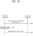
- FIG. 10 is a flowchart illustrating an existing method of performing measurement.
- UE receives measurement configuration information from a BS (S1010).
- a message including the measurement configuration information is called a measurement configuration message.
- the UE performs measurement based on the measurement configuration information (S1020).
- the UE reports a measurement result to the BS if the measurement result satisfies a report condition within the measurement configuration information (S1030).
- a message including the measurement result is called a measurement report message.
- the measurement configuration information may include the following information.
- UE In order to perform a measurement procedure, UE has a measurement object list, a measurement report configuration list, and a measurement identity list.
- a BS may configure only one measurement object for one frequency band regarding UE.
- E-UTRA Evolved Universal Terrestrial Radio Access
- RRC Radio Resource Control
- Protocol specification Release 8
- the UE If the measurement report of UE satisfies a set event, the UE transmits a measurement report message to a BS.
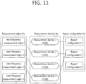
- FIG. 11 shows an example of a measurement configuration configured for UE.
- a measurement identity 1(1101) connects an intra-frequency measurement object and a reporting configuration 1.
- UE performs intra-frequency measurement, and the reporting configuration 1 is used to determine a reference and report type for a measurement result report.
- a measurement identity 2(1102) is connected to the intra-frequency measurement object, but the measurement identity 2(1102) connects the intra-frequency measurement object and a reporting configuration 2.
- UE performs intra-frequency measurement, and the reporting configuration 2 is used to determine a reference and a report type for a measurement result report.
- UE Based on the measurement identity 1(1101) and the measurement identity 2(1102), UE transmits a measurement result of the intra-frequency measurement object if the measurement result satisfies any one of the reporting configuration 1 and the reporting configuration 2.
- a measurement identity 3(1103) connects an inter-frequency measurement object 1 and a reporting configuration 3.
- UE reports a measurement result of the inter-frequency measurement object 1 if the measurement result satisfies a report condition included in the reporting configuration 1.
- a measurement identity 4(1104) connects an inter-frequency measurement object 2 and the reporting configuration 2.
- UE reports a measurement result of the inter-frequency measurement object 2 if the measurement result satisfies a report condition included in the reporting configuration 2.
- a measurement object, a reporting configuration and/or a measurement identity may be added, changed and/or deleted. This may be indicated when a BS transmits a new measurement configuration message to UE or transmits a measurement configuration change message to the UE.
- FIG. 12 shows an example in which a measurement identity is deleted.
- a measurement identity 2(1102) is deleted, measurement for a measurement object associated with the measurement identity 2(1102) is suspended, and a measurement report is not also transmitted.
- a measurement object or a reporting configuration associated with the deleted measurement identity may not be changed.
- FIG. 13 shows an example in which a measurement object is deleted.
- UE When an inter-frequency measurement object 1 is deleted, UE also deletes an associated measurement identity 3(1103). Measurement for the inter-frequency measurement object 1 is suspended, and a measurement report is also not transmitted. However, a reporting configuration associated with the deleted intra-frequency measurement object 1 may not be changed or deleted.
- UE When a reporting configuration is removed, UE also removes an associated measurement identity. UE suspends measurement for a measurement object associated by the associated measurement identity. However, a measurement object associated with the deleted reporting configuration may not be changed or deleted.
- a measurement report may include a measurement identity, the measured quality of a serving cell, and a measurement result of a neighboring cell.
- the measurement identity identifies a measurement object whose measurement report has been triggered.
- the measurement result of the neighboring cell may include a cell identity and measured quality of the neighboring cell.
- the measured quality may include at least one of Reference Signal Received Power (RSRP) and Reference Signal Received Quality (RSRQ).
- MDT Minimization Drive Test
- An MDT enables UE to perform measurement and report a result thereof instead of a drive test in which conventional service providers measure the quality of cells using vehicles for cell coverage optimization. Coverage varies depending on the location of a BS, the deployment of peripheral buildings, and a use environment of a user. Accordingly, a service provider needs to periodically perform a drive test, which consumes lots of costs and resources. In order to overcome the disadvantages, there is proposed an MDT in which a service provider measures coverage using UE.
- a service provider may write a coverage map, indicating whether or not service is possible over the entire area to which service is provided by a service provider and a distribution of QoS, by synthesizing MDT measurement values received from several pieces of UE and use the written coverage map in network operations and optimization. For example, when a report on a coverage problem for a specific area is received from UE, a service provider may enlarge the coverage of a corresponding area cell by increasing the transmission power of a BS that provides service to the corresponding area. The time and cost necessary for network optimization can be minimized through such a method.
- An MDT has been produced based on the framework of a tracking function, that is, one of the tools of an operator for Operation, Administration, and Maintenance (OAM).
- the tracking function provides an operator with the ability to perform tracking and to log the behaviors of UE and thus can enable the operator to determine the major cause of a function failure on the UE side.
- Traced data is collected over a network, which is called a Trace Collection Entity (TCE).
- TCE Trace Collection Entity
- An operator uses data collected in a TCE for analysis and evaluation.
- a tracking function used for an MDT includes signaling based on a tracking function and management based on tracking function. Signaling based on a tracking function is used to activate an MDT task toward specific UE, whereas management based on tracking functions is used to activate an MDT task without being limited to specific UE.
- An MDT may be divided into two types: a logged MDT and an immediate MDT depending on whether UE reports measured and stored log data in a non-real time or in real time.
- the logged MDT is a method of UE performing MDT measurement, logging corresponding data, and sending the logged data to a network.
- the immediate MDT is a method of UE performing MDT measurement and immediately sending corresponding data to a network.
- UE performs MDT measurement in the RRC_idle state.
- the immediate MDT UE performs MDT measurement in the RRC_connected state.
- FIG. 14 is a flowchart illustrating a method of performing a logged MDT.
- the logged measurement configuration may be included in an RRC message and transmitted through a downlink control channel.
- the logged measurement configuration may include at least one of a TCE ID, information about a reference time that is a basis for logging, logging duration, a logging interval, and information about an area configuration.
- the logging interval indicates an interval in which a measurement result is stored.
- the logging duration indicates duration for which UE performs a logged MDT.
- the reference time indicates a reference time for duration for which a logged MDT is performed.
- the area configuration indicates an area that has been requested to be logged by UE.
- the validity timer means the lifetime of the logged measurement configuration, which may be specified by information about logging duration.
- the duration of the validity timer may indicate the validity of measurement results owned by UE as well as the valid lifetime of a logged measurement configuration.
- a procedure in which UE performs a logged measurement configuration and a corresponding overall procedure is performed as described above is called a configuration phase.
- the UE When the UE enters the RRC_idle state (S1421), the UE logs the measurement result while the validity timer is driven (S1422).
- a measurement result value may include RSRP, RSRQ, Received Signal Code Power (RSCP), Ec/No, etc.
- Information on which a measurement result has been logged is called logged measurement.
- a temporal interval in which UE logs a measurement result one or more times is called a logging phase.
- the execution of a logged MDT based on a logged measurement configuration by UE may vary depending on the location of the UE.
- FIG. 15 is a diagram showing an example of a logged MDT according to a logging area.
- a network may configure a logging area that is an area in which UE has to log.
- the logging area may be represented as a cell list or a tracking area/location area list. If a logging area is configured in UE, the UE suspends logging when the UE gets out of the logging area.
- a first area 1510 and a third area 1530 are areas configured as logging areas, and a second area 1520 is an area in which logging is not permitted.
- UE performs logging in the first area 1510, but does not perform logging in the second area 1520.
- UE performs logging again when the UE moves from the second area 1520 to the third area 1530.
- FIG. 16 is a diagram showing an example of a logged MDT according to a change of RAT.
- the UE performs logging only when the UE camps on RAT from which a logged measurement configuration has been received and suspends logging in another RAT.
- the UE may log cell information about other RATs in addition to camp-on RAT.
- a first area 1610 and a third area 1630 are E-UTRAN areas, and a second area 1620 is a UTRAN area.
- a logged measurement configuration is received from the E-UTRAN.
- the UE When UE enters the second area 1620, the UE does not perform MDT measurement.
- the UE enters the RRC_connected state (S1431). If logged measurement to be reported is present, the UE informs an eNB that the logged measurement to be reported is present (S1432). The UE may inform the eNB that the logged measurement is present when an RRC connection is established, an RRC connection is reestablished, or an RRC connection is reconfigured. Furthermore, if the UE performs handover, the UE may inform a handover target cell of a presence of the logged measurement.
- Informing, by the UE, the eNB that the logged measurement is present may include including a logged measurement-available indicator, that is, indication information informing that the logged measurement is present, in an RRC message transmitted from the UE to the eNB and sending the RRC message.
- the RRC message may be an RRC connection configuration complete message, an RRC connection reestablishment complete message, an RRC reconfiguration complete message, or a handover complete message.
- the eNB When the eNB receives a signal informing that the logged measurement is present from the UE, the eNB request the UE to report logged measurement (S1433). Requesting the report on the logged measurement may include including a logged measurement report request parameter regarding information indicative of the request in an RRC message and sending the RRC message.
- the RRC message may be a UE information request message.
- reporting the logged measurement to the eNB may include including the logged measurement report, including pieces of logged measurement, in an RRC message and sending the RRC message to the eNB.
- the RRC message may be a UE information report message.
- the UE may report all or some of pieces of logged measurement owned by the UE on a report time point to the eNB. If the UE reports some of pieces of logged measurement, the reported pieces of logged measurement may be discarded.
- a phase of a process in which the UE informs the eNB that the logged measurement is present, receives a request to report the logged measurement from the eNB, and reports the logged measurement is performed as described above is called a report phase.
- a radio environment is chiefly measured by the UE while a logged MDT is performed.
- MDT measurement may include a cell identity and the signal quality and/or signal intensity of the cell.
- MDT measurement may include a measurement time and a measurement place.
- the following table illustrates contents logged by UE.
- Information logged at different logging time points can be classified and stored according to different log entries.
- FIG. 17 is a diagram showing an example of logged measurement.
- Logged measurement includes one or more log entries.
- the log entry includes a logging location, a logging time, a serving cell identity, a serving cell measurement result, and a neighboring cell measurement result.
- the logging location indicates the location where UE has performed measurement.
- the logging time indicates the time when UE has performed measurement. Pieces of information logged at different logging times are stored in different log entries.
- the serving cell identity may include a cell identity in the layer 3, which is called a Global Cell Identity (GCI).
- GCI Global Cell Identity
- the GCI is a set of a Physical Cell Identity (PCI) and a PLMN identity.
- UE may perform logging by analyzing criteria related to the performance of UE in addition to a radio environment.
- the criteria related to the performance of UE may include a throughput, an erroneous transmission/reception rate, etc.
- the aforementioned logging phase and report phase may be present in plural times for logging duration (S1441, S1442).
- the eNB may record/store the logged measurement on/in a TCE when the logged measurement is reported.
- the UE If the UE has logged measurement that has not been reported after the validity timer expires, that is, after the logging duration elapses, the UE performs a procedure for reporting the logged measurement to the eNB.
- a phase in which the overall procedure for the procedure is called a post-reporting phase.
- the UE discards the logged measurement configuration and initiates a conservation timer. After the logging duration is terminated, the UE suspends MDT measurement. However, the already logged measurement remains intact without being discarded.
- the conservation timer indicates the lifetime of the remaining logged measurement.
- the UE When the UE enters the RRC_connected state (S1451) before the conservation timer expires, the UE may report logged measurement to the eNB. In this case, the aforementioned procedure for a logged measurement report may be performed (S1452, S1453, S1454). When the conservation timer expires, the remaining logged measurement may be discarded. When the logged measurement is reported, the eNB may record/store the logged measurement on/in the TCE.
- the conservation timer may be fixed to a predetermined value in the UE and may be previously set in the UE. For example, a value of the conservation timer may be 48 hours. Or, a value of the conservation timer may be included in the logged measurement configuration and transferred to the UE or may be included in a different RRC message and transferred to the UE.
- the UE may update an existing logged measurement configuration into the newly obtained logged measurement configuration.
- the validity timer can be started again from the time when the logged measurement configuration is newly received.
- logged measurement based on the previous logged measurement configuration may be discarded.
- FIG. 18 is a diagram showing an example of an immediate MDT.
- the immediate MDT is based on a Radio Resource Management (RRM) measurement and report mechanism.
- RRM Radio Resource Management
- information related to the location upon a measurement report is added and reported to an eNB.
- UE receives an RRC connection reconfiguration message (S1810) and transmits an RRC connection reconfiguration complete message (S1820). Thus, the UE enters the RRC_connected state.
- the UE may receive a measurement configuration by receiving the RRC connection reconfiguration message.
- the measurement configuration has been illustrated as being received through the RRC connection reconfiguration message, but the measurement configuration may be included in a different RRC message and transmitted.
- the UE performs measurement and evaluation in the RRC_connected state (S1831) and reports a measurement result to the eNB (S1832).
- the measurement result may provide precise location information, as possible, as in the example of location information provided by a Global Navigation Satellite System (GNSS).
- GNSS Global Navigation Satellite System
- the measurement result may provide measurement information about a neighboring cell, which may be used to determine the location of UE.
- FIG. 19 is a diagram showing an example of a method of performing a logged MDT in accordance with an embodiment of the present invention.
- the logged measurement configuration may include the information included in the logged measurement configuration described with reference to FIG. 14 .
- the logged measurement configuration may further include pieces of the following time-related information.
- the logged measurement configuration may include logging start time information indicative of a point of time at which logging is started.
- the logged measurement configuration may include logging end time information indicative of a start point of time at which logging is terminated.
- the logged measurement configuration may include logging start time information and logging duration information indicative of a time interval in which logging is performed.
- UE may determine a point of time at which a logging execution time interval has elapsed from a logging start time to be a logging end time.
- the logged measurement configuration may include log report start time information indicative of a point of time at which logged measurement is reported.
- the logged measurement configuration may include log report end time information indicative of a point of time at which a logged measurement report is ended.
- the logged measurement configuration may include one or more of the pieces of above-described time-related information.
- the UE which has received logging start time information does not log a measurement result after MDT measurement although the UE enters an RRC idle state.
- the UE performs MDT measurement and logs a measurement result in the RRC idle state and from a logging start time (S1921).
- the measurement result logged by the UE may include the pieces of information included in the measurement result described with reference to FIG. 14 .
- the UE can perform MDT measurement and log a measurement result in each logging interval (S1922).
- the UE which has received logging end time information terminates the MDT measurement and the measurement result logging and discards the existing logged measurement configuration at the logging end time (S1930). However, the UE does not discard the logged measurement.
- the UE may consider that the logging end time has been reached, terminal the logging, and discard the existing logged measurement configuration.
- the UE which has received log report start time information does not report logged measurement to a network if the log report start time is not reached although the UE enters an RRC_connected state.
- the UE which has not received log report start time information may perform a procedure for reporting logged measurement when the UE enters an RRC_connected state after a logging end time is reached.
- the UE When a log report start time is reached, the UE reports the logged measurement (S1940). The UE sends a logged measurement-available indicator, indicating that the logged measurement to be reported is present, to the network (S1941). If the UE has already entered an RRC_connected state upon a report, the UE may include the logged measurement-available indicator in an RRC message and send the RRC message. If the UE has not entered an RRC _connected state when reporting a log, the UE can transmit and receive RRC messages that establish an RRC connection. Here, the UE may include a logged measurement-available indicator in a message that completes the establishment of the RRC connection and transmit the message to the network. The message that completes the establishment of the RRC connection may be an RRC connection setup complete message, an RRC connection reconfiguration complete message, or an RRC connection reestablishment complete message.
- the UE receive a logged measurement report request, transmitted in response to the logged measurement-available indicator, from the network (S1942) and reports the logged measurement to the network in response to the request (S1943).
- the logged measurement report request may be included in a UE information request message transmitted from the network to the UE and be then transmitted.
- the logged measurement configuration may be included in a UE information report message transmitted from the UE to the network and be then transmitted.
- the UE If the UE reports part of the logged measurement to the network through the logged measurement report step (S1940), the UE performs a logged measurement report again in order to report the remaining logged measurement (S1950).
- To report the logged measurement may include performing steps S1951 to S1953 as described above.
- the UE stops the report of the logged measurement. If logged measurement to be reported to the network is present, the UE may discard the remaining logged measurement (S1960).
- the UE may discard the remaining logged measurement.
- the conservation timer expires prior to the log report end time, the UE may discard the remaining logged measurement when the conservation timer expires.
- UE performs MDT measurement and logging only in an RRC idle state, but the UE may be implemented to perform MDT measurement and logging irrespective of a state. For example, UE may perform logging even in an RRC idle state and/or an RRC_connected state. In this case, when logging start time information is received, the UE may perform MDT measurement and logging from the logging start time. If a logging start time is not received, the UE may perform MDT measurement and logging from a point of time at which a logged measurement configuration is received.
- a measurement result may not be logged based on a logging interval, but a measurement result may be logged if quality of a serving cell is a specific threshold or lower.
- MDT measurement/report may be performed based on the above logging start time information and the logging end time information even when performing an immediate MDT.
- the measurement configuration transmitted to UE may further include measurement report start time information and/or measurement report end time information.
- the UE may perform measurement evaluation from the measurement report start time although the UE is in an RRC_connected state and report a measurement result to a network.
- the UE may stop measurement evaluation/report at the measurement report end time although the UE is in an RRC_connected state.
- a measurement result is reported right after MDT measurement. Therefore, information about a report start time and a report end time may not be included in a measurement configuration.
- a method of reporting radio link failure information or handover failure information can be performed based on the above-described time-related information.
- An example of a method of reporting radio link failure information is described below with reference to FIG. 20 .
- FIG. 20 is a flowchart illustrating a method of reporting radio link failure information in accordance with an embodiment of the present invention.
- a network transmits RLF configuration information, including time-related information, to UE (S2010).
- the RLF configuration information may include generation start time information on which the UE detects a radio link failure and starts generating radio link failure information.
- the RLF configuration information may include generation end time information on which the generation of radio link failure information is stopped.
- the RLF configuration information may include generation start time information and generation duration information, that is, a time interval in which radio link failure information is generated from a generation start time. If the generation duration elapses from the generation start time, the UE may determine that it is a generation end time.
- the RLF configuration information may include report start time information indicative of the time when the UE starts reporting generated radio link failure information to the network.
- the RLF configuration information may include report end time information indicative of the time when the report of radio link failure information is stopped.
- the RLF configuration information may include one or more of the above-described pieces of information.
- the UE which has received generation start time information does not generate radio link failure information although it detects a radio link failure prior to the generation start time (S2020).
- the UE which has received generation start time information generates radio link failure information when it detects a radio link failure after the generation start time (S2030).
- the UE may not report the generated radio link failure information to the network before a report start time is reached.
- the UE When the UE detects a radio link failure again prior to a generation end time, the UE generates new radio link failure information (S2040).
- the UE may update existing radio link failure information into the new radio link failure information.
- the UE may store the new radio link failure information independently from the existing radio link failure information.
- the UE may not generate radio link failure information although it detects a radio link failure.
- the UE which has not obtained information about a generation end time may generate radio link failure information until a report start time or a report end time.
- the UE may report radio link failure information (S2050).
- the UE transmits a logged measurement-available indicator, indicating that logged measurement to be reported is present, to the network (S2051). If the UE has already entered the RRC_connected state upon a report, the UE can include a radio link failure information-available indicator in an RRC message and transmit the RRC message. If the UE has not entered the RRC _connected state when reporting a log, the UE transmits and receives RRC messages for establishing an RRC connection.
- the UE can include a message that completes the establishment of the RRC connection in the radio link failure information-available indicator and transmit the message to the network.
- the message that completes the RRC connection can be an RRC connection setup complete message, an RRC connection reconfiguration complete message, or an RRC connection reestablishment complete message.
- the UE may discard radio failure information without reporting the radio failure information to the network although the UE has the radio failure information to be reported.
- UE may perform logging or generate radio link failure information for a specific time interval and report logged measurement and the generated radio link failure information to a network for a specific time interval. Accordingly, the network may obtain a logged measurement result more efficiently because the UE intensively performs logging at a necessary time. Or, since UE detects a radio link failure and generates and reports radio link failure information at a necessary time, a network can obtain corresponding information efficiently. UE reports logged measurement or generated radio link failure information to a network within a specific time interval, so-called within a time zone in which occurrence frequency of traffic is low. Accordingly, a loss of information due to a lapse of time can be prevented from occurring.
- a network can implement the optimization of a wireless communication system more effectively based on information obtained as described above.
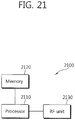
- FIG. 21 is a block diagram showing a radio device in which an embodiment of the present invention can be implemented.
- the device can implement the operation of UE in the embodiments of FIGS. 19 and 20 .
- the radio device 2100 includes a processor 2110, memory 2120, and a Radio Frequency (RF) unit 2130.
- the processor 2110 implements the proposed functions, processes and/or methods.
- the processor 2110 can be configured to perform a logged MDT based on a logged measurement configuration including time-related information.
- the processor 2110 can be configured to log MDT measurement in a specific time interval based on the time-related information and to report the logged measurement to a network in another specific time interval.
- the processor 2110 can be configured to perform a radio link failure information report based on the RLF configuration information.
- the processor 2110 can be configured to generate radio link failure information in a specific time interval and to report radio link failure information to a network in another specific time interval.
- FIGS. 19 and 20 can be implemented by the processor 2110 and the memory 2120.
- the RF unit 2130 is connected to the processor 2110, and it transmits and receives radio signals.
- the processor 2110 may include Application-Specific Integrated Circuits (ASICs), other chipsets, logic circuits, and/or data processor 2110s.
- the memory 2120 may include Read-Only Memory (ROM), Random Access Memory (RAM), flash memory 2120, memory 2120 cards, storage media and/or other storage devices.
- the RF unit 2130 may include a baseband circuit for processing radio signals.
- the above-described embodiment is implemented in software, the above-described scheme may be implemented into a module (process or function) configured to perform the above function.
- the module may be stored in the memory 2120 and executed by the processor 2110.
- the memory 2120 may be placed inside or outside the processor 2110 and connected to the processor 2110 using a variety of well-known means.
Claims (8)
- Procédé de réalisation, par un équipement utilisateur, UE, d'une minimisation de test de couverture radio, MDT, dans un système de communication sans fil, le procédé comprenant :recevoir une configuration de mesure journalisée ;réaliser une mesure MDT et journaliser un résultat de mesure sur la base de la configuration de mesure journalisée,la configuration de mesure journalisée comprenant des informations de temps de début de journalisation indiquant un temps de début lorsque la réalisation de la mesure MDT et la journalisation du résultat de mesure sont autorisées,la configuration de mesure journalisée comprenant des informations de temps de fin de journalisation indiquant que la mesure MDT et la journalisation de résultat de mesure sont terminées, la mesure MDT et la journalisation du résultat de mesure sont réalisées lorsque le temps de début indiqué par les informations de temps de début de journalisation est atteint et jusqu'au temps de fin indiqué par les informations de temps de fin de journalisation,la configuration de mesure journalisée comprenant des informations d'intervalle de journalisation, les informations d'intervalle de journalisation indiquant un intervalle de temps spécifique, et l'étape consistant à réaliser la mesure MDT et à journaliser le résultat de mesure étant réalisée périodiquement selon l'intervalle de temps spécifique,l'intervalle de temps spécifique étant réglé par un réseau ;écarter la configuration de mesure journalisée et initier un temporisateur de conservation lorsque le temps de fin indiqué par les informations de temps de fin de journalisation s'écoule ; etécarter la mesure journalisée lorsque le temporisateur de conservation expire,le temporisateur de conservation expirant au bout de 48 heures après l'écartement de la configuration de mesure journalisée,caractérisé par le fait que la configuration de mesure journalisée comprend des informations de temps de début de rapport de journalisation, les informations de temps de début de rapport de journalisation indiquant un temps de début lorsque le rapport est autorisé, et par le fait que la configuration de mesure journalisée comprend en outre des informations de temps de fin de rapport de journalisation, les informations de temps de fin de rapport de journalisation indiquant un temps de fin lorsque le rapport est terminé, le rapport étant réalisé lorsque le temps de début indiqué par le temps de début de rapport de journalisation est atteint et jusqu'au temps de fin indiqué par le temps de fin de rapport de journalisation,le procédé comprenant en outre l'écartement d'un résultat de mesure journalisé restant si le temps de fin indiqué par les informations de temps de fin de rapport de journalisation s'écoule.
- Procédé selon la revendication 1, dans lequel l'UE est dans un état de repos de commande de ressources radio, RRC, à un point du temps auquel la mesure MDT est réalisée et le résultat de mesure est journalisé.
- Procédé selon la revendication 1, dans lequel le résultat de mesure journalisé restant non rapporté est présent dans le résultat de mesure journalisé.
- Procédé selon la revendication 1, dans lequel, à un point du temps auquel une partie ou la totalité de la mesure journalisée est rapportée, l'UE est dans un état connecté RRC.
- Appareil sans fil (2100) comprenant :une unité radiofréquence, RF, (2130) émettant et recevant des signaux radio ; etun processeur (2110) couplé de manière fonctionnelle à l'unité RF, le processeur étant configuré pour :recevoir une configuration de mesure journalisée ;réaliser une mesure de minimisation de test de couverture radio, MDT, et journaliser un résultat de mesure sur la base de la configuration de mesure journalisée ;la configuration de mesure journalisée comprenant des informations de temps de début de journalisation indiquant un temps de début lorsque la réalisation de la mesure MDT et la journalisation du résultat de mesure sont autorisées,la configuration de mesure journalisée comprenant des informations de temps de fin de journalisation indiquant que la mesure MDT et la journalisation de résultat de mesure sont terminées,la mesure MDT et la journalisation du résultat de mesure étant réalisées lorsque le temps de début indiqué par les informations de temps de début de journalisation est atteint et jusqu'au temps de fin indiqué par les informations de temps de fin de journalisation,la configuration de mesure journalisée comprenant des informations d'intervalle de journalisation, les informations d'intervalle de journalisation indiquant un intervalle de temps spécifique, et l'étape consistant à réaliser la mesure MDT et à journaliser le résultat de mesure étant réalisée périodiquement selon l'intervalle de temps spécifique,l'intervalle de temps spécifique étant réglé par un réseau ;écarter la configuration de mesure journalisée et initier un temporisateur de conservation lorsque le temps de fin indiqué par les informations de temps de fin de journalisation s'écoule ; etécarter la mesure journalisée lorsque le temporisateur de conservation expire,le temporisateur de conservation expirant au bout de 48 heures après l'écartement de la configuration de mesure journalisée,caractérisé par le fait que la configuration de mesure journalisée comprend des informations de temps de début de rapport de journalisation, les informations de temps de début de rapport de journalisation indiquant un temps de début lorsque le rapport est autorisé, et par le fait que la configuration de mesure journalisée comprend en outre des informations de temps de fin de rapport de journalisation, les informations de temps de fin de rapport de journalisation indiquant un temps de fin lorsque le rapport est terminé, le rapport étant réalisé lorsque le temps de début indiqué par le temps de début de rapport de journalisation est atteint et jusqu'au temps de fin indiqué par le temps de fin de rapport de journalisation,le processeur étant en outre configuré pour écarter un résultat de mesure journalisé restant si le temps de fin indiqué par les informations de temps de fin de rapport de journalisation s'écoule.
- Appareil sans fil (2100) selon la revendication 5, dans lequel l'appareil sans fil est dans un état de repos de commande de ressources radio, RRC, à un point du temps auquel la mesure de minimisation de test de couverture radio est réalisée et le résultat de mesure est journalisé.
- Appareil sans fil (2100) selon la revendication 5, dans lequel le résultat de mesure journalisé restant non rapporté est présent dans le résultat de mesure journalisé.
- Appareil sans fil (2100) selon la revendication 5, dans lequel, à un point du temps auquel la totalité ou une partie de la mesure journalisée est rapportée, l'UE est dans un état connecté de commande de ressources radio.
Applications Claiming Priority (2)
| Application Number | Priority Date | Filing Date | Title |
|---|---|---|---|
| US201161479835P | 2011-04-27 | 2011-04-27 | |
| PCT/KR2012/003265 WO2012148205A2 (fr) | 2011-04-27 | 2012-04-26 | Procédé d'exécution de minimisation de test de couverture radio (mdt) dans un système de communication sans fil et dispositif prenant en charge ce dernier |
Publications (3)
| Publication Number | Publication Date |
|---|---|
| EP2704471A2 EP2704471A2 (fr) | 2014-03-05 |
| EP2704471A4 EP2704471A4 (fr) | 2015-04-22 |
| EP2704471B1 true EP2704471B1 (fr) | 2018-10-03 |
Family
ID=47072928
Family Applications (4)
| Application Number | Title | Priority Date | Filing Date |
|---|---|---|---|
| EP12777079.0A Not-in-force EP2704472B1 (fr) | 2011-04-27 | 2012-04-26 | Procédé de notification dans un système de communication sans fil et dispositif prenant en charge ce dernier |
| EP12777527.8A Not-in-force EP2704474B1 (fr) | 2011-04-27 | 2012-04-26 | Procédé d'enregistrement et de notification d'informations de réseau hétérogène dans un système de communication sans fil et dispositif prenant en charge ce dernier |
| EP12777304.2A Not-in-force EP2704473B1 (fr) | 2011-04-27 | 2012-04-26 | Procédé d'enregistrement et de notification d'informations sur des interférences par un terminal idc dans un système de communication sans fil et dispositif prenant en charge ce dernier |
| EP12776708.5A Not-in-force EP2704471B1 (fr) | 2011-04-27 | 2012-04-26 | Procédé d'exécution de minimisation de test de couverture radio (mdt) dans un système de communication sans fil et dispositif prenant en charge ce dernier |
Family Applications Before (3)
| Application Number | Title | Priority Date | Filing Date |
|---|---|---|---|
| EP12777079.0A Not-in-force EP2704472B1 (fr) | 2011-04-27 | 2012-04-26 | Procédé de notification dans un système de communication sans fil et dispositif prenant en charge ce dernier |
| EP12777527.8A Not-in-force EP2704474B1 (fr) | 2011-04-27 | 2012-04-26 | Procédé d'enregistrement et de notification d'informations de réseau hétérogène dans un système de communication sans fil et dispositif prenant en charge ce dernier |
| EP12777304.2A Not-in-force EP2704473B1 (fr) | 2011-04-27 | 2012-04-26 | Procédé d'enregistrement et de notification d'informations sur des interférences par un terminal idc dans un système de communication sans fil et dispositif prenant en charge ce dernier |
Country Status (4)
| Country | Link |
|---|---|
| US (4) | US9237468B2 (fr) |
| EP (4) | EP2704472B1 (fr) |
| KR (4) | KR101547749B1 (fr) |
| WO (4) | WO2012148205A2 (fr) |
Cited By (1)
| Publication number | Priority date | Publication date | Assignee | Title |
|---|---|---|---|---|
| EP3863234B1 (fr) * | 2016-03-25 | 2023-12-13 | Voapps, Inc. | Signalisation adaptative pour mesure de performance de réseau, accès et contrôle |
Families Citing this family (92)
| Publication number | Priority date | Publication date | Assignee | Title |
|---|---|---|---|---|
| KR20120102106A (ko) | 2010-01-07 | 2012-09-17 | 닛본 덴끼 가부시끼가이샤 | 무선 통신 시스템, 무선 단말, 무선 네트워크, 무선 통신 방법 및 프로그램 |
| US9398477B2 (en) * | 2011-04-29 | 2016-07-19 | Telefonaktiebolaget L M Ericsson | Method and arrangement for assisting a network management unit |
| US9609538B2 (en) * | 2011-06-03 | 2017-03-28 | Samsung Electronics Co., Ltd | Method and apparatus for efficiently controlling an MDT in a plurality of PLMNS |
| TWI477183B (zh) * | 2011-08-10 | 2015-03-11 | Mediatek Inc | 管理事件資訊存取的方法和用戶設備 |
| CN102932823A (zh) * | 2011-08-10 | 2013-02-13 | 华为技术有限公司 | 关联报告的方法及装置 |
| KR102092579B1 (ko) | 2011-08-22 | 2020-03-24 | 삼성전자 주식회사 | 이동통신 시스템에서 복수 개의 주파수 밴드 지원 방법 및 장치 |
| US9380480B2 (en) * | 2011-08-25 | 2016-06-28 | Kyocera Corporation | Minimization drive test with reduced wireless device memory usage |
| EP2749064B1 (fr) * | 2011-09-30 | 2019-12-04 | Nokia Solutions and Networks Oy | Filtrage de rapport de panne de liaison hertzienne |
| WO2013100658A1 (fr) * | 2011-12-27 | 2013-07-04 | Pantech Co., Ltd. | Appareil et procédé de commande des interférences de coexistence intra-dispositif dans un système de communication sans fil |
| CN104137600B (zh) * | 2012-01-09 | 2018-10-12 | 三星电子株式会社 | 用于记录的方法和装置 |
| CN103200607A (zh) * | 2012-01-09 | 2013-07-10 | 电信科学技术研究院 | 一种在mdt过程中确定ue定位信息的方法及装置 |
| US9049698B2 (en) * | 2012-01-18 | 2015-06-02 | Mediatek Inc. | Method of enhanced connection recovery and cell selection |
| US10531264B2 (en) | 2012-01-27 | 2020-01-07 | Samsung Electronics Co., Ltd. | Method and apparatus for efficiently controlling access for system load adjustment in mobile communication systems |
| US9414409B2 (en) | 2012-02-06 | 2016-08-09 | Samsung Electronics Co., Ltd. | Method and apparatus for transmitting/receiving data on multiple carriers in mobile communication system |
| US9271169B2 (en) * | 2012-02-23 | 2016-02-23 | Ace Incorporated | Method of reporting link failure |
| TW201340756A (zh) * | 2012-03-19 | 2013-10-01 | Innovative Sonic Corp | 記錄和回報可能會於無線通訊網路中造成存取問題的事件之方法和裝置 |
| WO2013151386A1 (fr) * | 2012-04-06 | 2013-10-10 | 엘지전자 주식회사 | Procédé de transmission de rapports dans un système de communication sans fil et appareil permettant de mettre en œuvre ce procédé |
| US9144003B2 (en) * | 2012-05-02 | 2015-09-22 | Qualcomm Incorporated | Apparatus and method for a connected mode with reduced signaling |
| US9565622B2 (en) * | 2012-07-05 | 2017-02-07 | Qualcomm Incorporated | Detecting services provided by a wireless node before device discovery and connection establishment |
| EP3582552A1 (fr) * | 2012-08-02 | 2019-12-18 | Huawei Technologies Co., Ltd. | Terminal et procédé de traitement après un échec d'accès au terminal |
| JPWO2014021463A1 (ja) * | 2012-08-03 | 2016-07-21 | 京セラ株式会社 | ユーザ端末、プロセッサ、及び方法 |
| US9374715B2 (en) * | 2012-09-26 | 2016-06-21 | Telefonaktiebolaget Lm Ericsson (Publ) | Intercell interference coordination for machine to machine communications |
| EP2901744B1 (fr) * | 2012-09-27 | 2016-11-23 | Telefonaktiebolaget LM Ericsson (publ) | Procédé permettant de gérer le consentement d'un utilisateur pour la collecte de données de mdt |
| US8891396B2 (en) * | 2012-10-24 | 2014-11-18 | Intel Mobile Communications GmbH | Communication device, mobile terminal, method for requesting information and method for providing information |
| US9674723B2 (en) | 2012-11-05 | 2017-06-06 | Telefonaktiebolagent L M Ericsson (Publ) | Systems and methods for maintaining time stamping accuracy to meet a non-linear time drift constraint |
| WO2014073940A1 (fr) * | 2012-11-12 | 2014-05-15 | 엘지전자 주식회사 | Procédé de resélection de cellule dans un système de communication sans fil et appareil le prenant en charge |
| WO2014084499A1 (fr) * | 2012-11-29 | 2014-06-05 | Lg Electronics Inc. | Procédé de mesure de latence et appareil associé |
| WO2014106347A1 (fr) | 2013-01-07 | 2014-07-10 | 华为技术有限公司 | Procédé, appareil et système permettant de collecter des informations sur les points d'accès d'un réseau local sans fil |
| KR101701079B1 (ko) * | 2013-01-13 | 2017-01-31 | 애플 인크. | 측정 빈도 감소를 통한 소비전력 감소 |
| US9198184B2 (en) | 2013-01-30 | 2015-11-24 | Intel Corporation | Dynamic interference avoidance in integrated multi-radio access technologies (RAT) heterogeneous networks |
| US9973902B2 (en) * | 2013-02-14 | 2018-05-15 | Lg Electronics Inc. | Method for reporting MBMS information in wireless communication system and device for supporting same |
| US9351183B2 (en) * | 2013-02-26 | 2016-05-24 | Google Technology Holdings LLC | Apparatus and method for measuring and using congestion in a wireless communication system |
| US9913155B2 (en) | 2013-03-06 | 2018-03-06 | Lg Electronics Inc. | Method and apparatus for handling traffic steering failure in wireless communication system |
| US9854459B2 (en) * | 2013-03-12 | 2017-12-26 | Qualcomm Incorporated | Network-based alarming and network-based reconfiguration |
| US9338700B2 (en) | 2013-03-20 | 2016-05-10 | Qualcomm Incorporated | Inter-RAT transitioning utilizing system information messaging |
| WO2014157074A1 (fr) * | 2013-03-25 | 2014-10-02 | 京セラ株式会社 | Procédé de commande de communication, terminal d'utilisateur, dispositif de réseau, et station de base |
| KR102036061B1 (ko) * | 2013-04-08 | 2019-11-26 | 삼성전자 주식회사 | 무선 통신 시스템에서 단말기가 mbms 관련 측정 정보를 기록하고 보고하는 방법 및 장치 |
| KR102049391B1 (ko) * | 2013-04-12 | 2020-01-08 | 주식회사 팬택 | 이종 네트워크 무선 통신 시스템에서 셀 변경 방법 및 그 장치 |
| US9668162B2 (en) | 2013-04-15 | 2017-05-30 | Telefonaktiebolaget Lm Ericcson (Publ) | Signaling of system information to MTC-devices |
| KR102042581B1 (ko) | 2013-04-30 | 2019-11-08 | 삼성전자 주식회사 | 이동 통신 시스템에서 mdt 측정 정보 송수신 방법 및 장치 |
| US9693334B2 (en) | 2013-05-20 | 2017-06-27 | Kyocera Corporation | Communication control method and user terminal |
| EP3025540A4 (fr) * | 2013-07-26 | 2017-03-15 | Intel IP Corporation | Signalisation d'informations d'interférence pour aider un matériel utilisateur |
| US9125112B2 (en) * | 2013-08-06 | 2015-09-01 | Blackberry Limited | Communicating radio resource configuration information |
| GB2517911B (en) * | 2013-08-29 | 2016-06-22 | Nec Corp | Radio measurement reporting |
| US10341890B2 (en) * | 2013-12-13 | 2019-07-02 | Qualcomm Incorporated | CSI feedback in LTE/LTE-advanced systems with unlicensed spectrum |
| WO2015106439A1 (fr) * | 2014-01-17 | 2015-07-23 | 华为技术有限公司 | Équipement d'utilisateur, dispositif de réseau, et procédé de mesurage de minimisation des essais de conduite consignée |
| CN104093162B (zh) * | 2014-01-27 | 2019-03-05 | 中兴通讯股份有限公司 | 一种mbms最小化路测的方法、系统、基站和ue |
| CN105934969B (zh) * | 2014-01-29 | 2019-04-05 | Lg电子株式会社 | 在无线通信系统中发送报告消息的方法和装置 |
| GB2522671B (en) | 2014-01-31 | 2017-10-11 | Samsung Electronics Co Ltd | Measurement in MBMS |
| CN106031214B (zh) | 2014-03-13 | 2019-09-10 | Lg电子株式会社 | 无线通信系统中执行选择性mbms mdt的方法和装置 |
| WO2015137656A1 (fr) * | 2014-03-14 | 2015-09-17 | Lg Electronics Inc. | Procédé et appareil de reconfiguration mbms-mdt dans un système de communication sans fil |
| US10015641B2 (en) | 2014-03-15 | 2018-07-03 | Lg Electronics Inc. | Method and apparatus for configuring MBMS MDT for multiple MBSFN areas in wireless communication system |
| CN104936149A (zh) * | 2014-03-19 | 2015-09-23 | 中兴通讯股份有限公司 | 一种实现mbms最小化路测配置的方法、系统及设备 |
| WO2015141850A1 (fr) * | 2014-03-20 | 2015-09-24 | 京セラ株式会社 | Station mobile, procédé de commande de mesure, processeur et station de base |
| US9756602B2 (en) | 2014-03-27 | 2017-09-05 | Telefonatkiebolaget LM Ericsson (publ) | Node and method for radio measurement handling |
| KR101821693B1 (ko) * | 2014-03-28 | 2018-01-24 | 후아웨이 디바이스 (둥관) 컴퍼니 리미티드 | 로밍 네트워크 액세스 방법 및 장치 |
| US9955445B2 (en) * | 2014-04-01 | 2018-04-24 | Samsung Electronics Co., Ltd | System and method for enhancing reporting information for radio link failure (RLF) in LTE networks |
| TWI687109B (zh) * | 2014-04-03 | 2020-03-01 | 南韓商三星電子股份有限公司 | 用於在行動通訊網路中處置公眾陸地行動網路選擇的方法、使用者設備以及非暫時性電腦可讀媒體 |
| EP2934039B1 (fr) * | 2014-04-15 | 2019-03-20 | Telefonaktiebolaget LM Ericsson (publ) | Technique permettant de signaler un événement |
| WO2015171165A1 (fr) * | 2014-05-09 | 2015-11-12 | Nokia Technologies Oy | Restriction de plmn pour rapport de mesures de mbsfn |
| KR102179047B1 (ko) * | 2014-05-09 | 2020-11-16 | 삼성전자 주식회사 | 이동 통신 시스템에서 네트워크가 mbms 관련 측정 정보를 기록하고 보고할 단말기를 선정하여 설정하고, 단말기가 기록된 정보를 기지국에 보고하는 방법 및 장치 |
| CN106416352B (zh) * | 2014-05-16 | 2019-11-05 | Lg电子株式会社 | 无线通信系统中指示记录的mbms测量可用性的方法和装置 |
| CN111432491A (zh) * | 2014-05-20 | 2020-07-17 | 索尼公司 | 无线通信系统中的电子设备、方法和计算机可读存储介质 |
| WO2016163824A1 (fr) * | 2015-04-08 | 2016-10-13 | 엘지전자 주식회사 | Procédé de priorisation sélective de fréquence exécuté par un terminal dans un système de communication sans fil, et terminal utilisant ce procédé |
| US10827426B2 (en) * | 2015-06-09 | 2020-11-03 | Telefonaktiebolaget Lm Ericsson (Publ) | Methods and apparatuses for monitoring a radio link |
| US10517132B2 (en) * | 2015-07-17 | 2019-12-24 | Telefonaktiebolaget Lm Ericsson (Publ) | Terminal devices, network nodes and methods of operating the same |
| EP3337225B1 (fr) | 2015-08-12 | 2021-07-14 | LG Electronics Inc. | Procédé et dispositif pour terminal effectuant une mesure de wlan |
| JP2018532289A (ja) * | 2015-09-10 | 2018-11-01 | グァンドン オッポ モバイル テレコミュニケーションズ コーポレーション リミテッド | チャネル測定と測定結果報告の方法 |
| WO2017052332A1 (fr) * | 2015-09-24 | 2017-03-30 | 엘지전자 주식회사 | Procédé d'exécution de journalisation par un terminal dans un système de communications sans fil, et terminal associé |
| EP3488644B1 (fr) * | 2016-07-22 | 2020-10-28 | Telefonaktiebolaget LM Ericsson (PUBL) | Allocation de codes de zone de suivi |
| WO2018044211A1 (fr) * | 2016-08-30 | 2018-03-08 | Telefonaktiebolaget Lm Ericsson (Publ) | Mappage de relations de cellules inter-réseaux |
| US10493248B2 (en) | 2016-11-09 | 2019-12-03 | Medtronic Vascular, Inc. | Chordae tendineae management devices for use with a valve prosthesis delivery system and methods of use thereof |
| CN107567073A (zh) * | 2017-07-05 | 2018-01-09 | 宇龙计算机通信科技(深圳)有限公司 | 搜网的方法、装置、终端及计算机可读存储介质 |
| US10630453B2 (en) * | 2017-08-10 | 2020-04-21 | At&T Intellectual Property I, L.P. | Facilitating restriction of channel state information to improve communication coverage in 5G or other next generation networks |
| EP3749007A4 (fr) * | 2018-02-06 | 2021-03-03 | Beijing Xiaomi Mobile Software Co., Ltd. | Procédé et appareil de configuration de mesure |
| JP7058716B2 (ja) * | 2018-02-15 | 2022-04-22 | 京セラ株式会社 | ユーザ装置 |
| JP6651239B2 (ja) * | 2018-03-22 | 2020-02-19 | ▲ホア▼▲ウェイ▼技術有限公司Huawei Technologies Co.,Ltd. | ワイヤレスローカルエリアネットワークのアクセスポイントに関する情報を収集するための方法、装置、およびシステム |
| US11363483B2 (en) | 2018-04-02 | 2022-06-14 | Lg Electronics Inc. | Method for constructing logged measurement entry and device supporting the same |
| CN110875837B (zh) * | 2018-08-31 | 2021-04-27 | 展讯通信(上海)有限公司 | Mdt测量日志的发送方法、终端及可读存储介质 |
| CN111432419B (zh) * | 2019-01-09 | 2023-02-24 | 中兴通讯股份有限公司 | 路测日志信息上报方法及装置 |
| WO2020198274A1 (fr) * | 2019-03-28 | 2020-10-01 | Kyocera Corporation | Journal mdt d'inactivité avec durée d'inactivité |
| US11095352B2 (en) * | 2019-04-03 | 2021-08-17 | Asustek Computer Inc. | Method and apparatus for handling IDC problems in NR in a wireless communication system |
| KR102501308B1 (ko) * | 2019-04-03 | 2023-02-17 | 한국전자통신연구원 | 데이터 분석 기반 오류 예측 및 네트워크 재구성 방법과 장치 |
| CN111836301B (zh) * | 2019-04-19 | 2022-02-11 | 上海华为技术有限公司 | 一种最小化路测方法、装置、设备及介质 |
| FR3098674B1 (fr) * | 2019-07-10 | 2023-02-10 | Orange | Terminal et procédé de collecte d’informations sur une couverture radio d’au moins un réseau de communication cellulaire |
| CN111800842B (zh) * | 2019-08-15 | 2023-06-16 | 维沃移动通信有限公司 | Rrc空闲或非激活状态下的移动性测量方法及设备 |
| US20230072998A1 (en) * | 2020-01-30 | 2023-03-09 | Telefonaktiebolaget Lm Ericsson (Publ) | Measurement Reporting Configuration |
| CN113498104A (zh) | 2020-04-08 | 2021-10-12 | 大唐移动通信设备有限公司 | 无线链路失败信息上报、获取方法、终端及网络侧设备 |
| WO2022000144A1 (fr) * | 2020-06-28 | 2022-01-06 | 北京小米移动软件有限公司 | Procédé de mesurage, station de base, terminal multimode, dispositif de communication et support de stockage |
| EP4323791A2 (fr) * | 2021-04-13 | 2024-02-21 | Qualcomm Incorporated | Partage de mesure de prs |
| US20230078374A1 (en) * | 2021-09-13 | 2023-03-16 | Qualcomm Incorporated | Data collection for non-public networks |
| CN117528796A (zh) * | 2022-08-03 | 2024-02-06 | 北京三星通信技术研究有限公司 | 节点执行的方法以及节点 |
Family Cites Families (26)
| Publication number | Priority date | Publication date | Assignee | Title |
|---|---|---|---|---|
| GB9702458D0 (en) * | 1997-02-06 | 1997-03-26 | British Telecomm | Adaptive distributed information network |
| US6167449A (en) * | 1997-11-19 | 2000-12-26 | Apple Computer, Inc. | System and method for identifying and locating services on multiple heterogeneous networks using a query by type |
| US6295453B1 (en) * | 1998-10-07 | 2001-09-25 | Telefonaktiebolaget Lm Ericsson (Publ) | Multi-full rate channel assignment for a cellular telephone system |
| US6535908B1 (en) * | 1999-11-16 | 2003-03-18 | William J. Johnson | System and method for call record search and call record verification for network certification |
| JP3543764B2 (ja) * | 2000-12-21 | 2004-07-21 | 日本電気株式会社 | 無線通信システム及び干渉波監視方法 |
| US7099305B1 (en) * | 2002-04-30 | 2006-08-29 | Covad Communications Group, Inc. | Systems and method for automated monitoring of availability in xDSL access networks |
| US7269199B2 (en) * | 2003-08-28 | 2007-09-11 | Lenovo (Singapore) Pte. Ltd. | Apparatus and method employing dynamic hop sequence adjustment in FHSS networks |
| US8094631B2 (en) * | 2005-12-09 | 2012-01-10 | Marvell World Trade Ltd. | Coexistence system and method for wireless network devices |
| HUE033683T2 (en) | 2007-06-18 | 2017-12-28 | Lg Electronics Inc | Procedure for performing user device upload direction connection synchronization in a wireless communication system |
| KR20090016431A (ko) | 2007-08-10 | 2009-02-13 | 엘지전자 주식회사 | 무선 통신 시스템에서 채널품질 보고 수행 방법 |
| US8345607B2 (en) | 2008-03-10 | 2013-01-01 | Marvell World Trade Ltd. | Coexistence and collocation of remote network and local network radios |
| US8958371B2 (en) * | 2008-09-12 | 2015-02-17 | Qualcomm Incorporated | Interference management for different wireless communication technologies |
| KR101479596B1 (ko) * | 2008-11-05 | 2015-01-26 | 삼성전자주식회사 | 무선 통신 네트워크의 측정 보고 방법 및 장치 |
| ES2368385T3 (es) * | 2009-01-29 | 2011-11-16 | Lg Electronics Inc. | Esquema de transmisión de señales para una gestión eficaz del canal dedicado mejorado común. |
| KR101638911B1 (ko) * | 2009-03-06 | 2016-07-12 | 엘지전자 주식회사 | 다중 안테나 무선 통신 시스템에서 듀얼 모드 이동 단말기 및 이를 위한 제어 방법 |
| US9332420B2 (en) | 2009-04-28 | 2016-05-03 | Samsung Electronics Co., Ltd | Method and apparatus for managing user equipment history information in wireless communication network |
| CN101931981B (zh) * | 2009-06-18 | 2013-08-28 | 华为技术有限公司 | 一种最小化路测日志测量方法及装置 |
| KR101707683B1 (ko) | 2009-06-24 | 2017-02-16 | 엘지전자 주식회사 | 무선 통신 시스템상에서 단말의 측정 보고를 네트워크로 전송하는 방법 |
| CN104936242B (zh) | 2009-09-29 | 2019-07-05 | 北京三星通信技术研究有限公司 | 处理无线链路失败报告的方法 |
| US9232462B2 (en) * | 2009-10-15 | 2016-01-05 | Qualcomm Incorporated | Methods and apparatus for cross-cell coordination and signaling |
| US8577360B2 (en) | 2010-04-12 | 2013-11-05 | Telefonaktiebolaget Lm Ericsson (Publ) | UE-based MDT measuring and reporting in a cellular radio access network |
| KR20150070432A (ko) * | 2010-04-29 | 2015-06-24 | 인터디지탈 패튼 홀딩스, 인크 | 네트워크 테스트를 위한 개인 무선 장치의 이용 |
| KR101454563B1 (ko) * | 2010-08-13 | 2014-10-23 | 지티이 코포레이션 | 단말 장치가 통신을 구현하는 방법 및 시스템 |
| SG10201506368RA (en) | 2010-08-13 | 2015-09-29 | Interdigital Patent Holdings | In-device interference mitigation |
| EP2625889B1 (fr) * | 2010-10-04 | 2016-04-20 | Telefonaktiebolaget LM Ericsson (publ) | Control de messages de rapport par le réseau dans un réseau de communications sans fil |
| US8400949B2 (en) * | 2011-01-07 | 2013-03-19 | Renesas Mobile Corporation | Limited system information decoding for automatic neighbor relations in mobile networks |
-
2012
- 2012-04-26 WO PCT/KR2012/003265 patent/WO2012148205A2/fr active Application Filing
- 2012-04-26 EP EP12777079.0A patent/EP2704472B1/fr not_active Not-in-force
- 2012-04-26 EP EP12777527.8A patent/EP2704474B1/fr not_active Not-in-force
- 2012-04-26 WO PCT/KR2012/003264 patent/WO2012148204A2/fr active Application Filing
- 2012-04-26 KR KR1020137029200A patent/KR101547749B1/ko active IP Right Grant
- 2012-04-26 KR KR1020137029199A patent/KR101547748B1/ko active IP Right Grant
- 2012-04-26 US US14/114,503 patent/US9237468B2/en not_active Expired - Fee Related
- 2012-04-26 WO PCT/KR2012/003263 patent/WO2012148203A2/fr active Application Filing
- 2012-04-26 EP EP12777304.2A patent/EP2704473B1/fr not_active Not-in-force
- 2012-04-26 US US14/114,486 patent/US8934846B2/en active Active
- 2012-04-26 EP EP12776708.5A patent/EP2704471B1/fr not_active Not-in-force
- 2012-04-26 WO PCT/KR2012/003262 patent/WO2012148202A2/fr active Application Filing
- 2012-04-26 US US14/114,470 patent/US8958755B2/en active Active
- 2012-04-26 KR KR1020137029201A patent/KR101547750B1/ko active IP Right Grant
- 2012-04-26 KR KR1020137029198A patent/KR101547417B1/ko active IP Right Grant
- 2012-08-26 US US14/114,488 patent/US9253671B2/en active Active
Non-Patent Citations (1)
| Title |
|---|
| "3rd Generation Partnership Project; Technical Specification Group Radio Access Network; Evolved Universal Terrestrial Radio Access (E-UTRA); Radio Resource Control (RRC); Protocol specification (Release 10)", 3GPP STANDARD; 3GPP TS 36.331, 3RD GENERATION PARTNERSHIP PROJECT (3GPP), MOBILE COMPETENCE CENTRE ; 650, ROUTE DES LUCIOLES ; F-06921 SOPHIA-ANTIPOLIS CEDEX ; FRANCE, no. V10.1.0, 30 March 2011 (2011-03-30), pages 1 - 290, XP050476531 * |
Cited By (1)
| Publication number | Priority date | Publication date | Assignee | Title |
|---|---|---|---|---|
| EP3863234B1 (fr) * | 2016-03-25 | 2023-12-13 | Voapps, Inc. | Signalisation adaptative pour mesure de performance de réseau, accès et contrôle |
Also Published As
Similar Documents
| Publication | Publication Date | Title |
|---|---|---|
| EP2704471B1 (fr) | Procédé d'exécution de minimisation de test de couverture radio (mdt) dans un système de communication sans fil et dispositif prenant en charge ce dernier | |
| EP2887740B1 (fr) | Procédé de signalisation dans un système de communication sans fil et appareil pour la mise en uvre de ce procédé | |
| EP2534873B1 (fr) | Appareil et procédé d'envoi de mesures consignées dans un système de communication sans fil | |
| EP2882207B1 (fr) | Procédé pour rapporter des données de mobilité dans un système de communication sans fil, et appareil pour la mise en oeuvre de ce procédé | |
| US9137697B2 (en) | Method and apparatus for performing logged measurement in a wireless communication system | |
| US8929832B2 (en) | Apparatus and method of reporting logged measurement in wireless communication system | |
| EP2922334B1 (fr) | Procédé de rapport de mesure dans un système de communication sans fil et dispositif destiné à fonctionner selon ledit procédé | |
| US9526014B2 (en) | Method and apparatus for reporting a logged measurement in a wireless communication system | |
| WO2013066123A1 (fr) | Procédé de resélection de cellule par application d'une priorité suprême dans un système de communication sans fil et appareil pour sa mise en œuvre | |
| KR102038001B1 (ko) | 무선 통신 시스템에서 보고 방법 및 이를 지원하는 장치 | |
| US9661610B2 (en) | Communication method based on automatic serving cell management in wireless communication system, and device for supporting same |
Legal Events
| Date | Code | Title | Description |
|---|---|---|---|
| PUAI | Public reference made under article 153(3) epc to a published international application that has entered the european phase |
Free format text: ORIGINAL CODE: 0009012 |
|
| 17P | Request for examination filed |
Effective date: 20131114 |
|
| AK | Designated contracting states |
Kind code of ref document: A2 Designated state(s): AL AT BE BG CH CY CZ DE DK EE ES FI FR GB GR HR HU IE IS IT LI LT LU LV MC MK MT NL NO PL PT RO RS SE SI SK SM TR |
|
| DAX | Request for extension of the european patent (deleted) | ||
| A4 | Supplementary search report drawn up and despatched |
Effective date: 20150324 |
|
| RIC1 | Information provided on ipc code assigned before grant |
Ipc: H04W 24/00 20090101AFI20150318BHEP Ipc: H04W 24/08 20090101ALI20150318BHEP Ipc: H04W 88/06 20090101ALI20150318BHEP Ipc: H04W 24/10 20090101ALI20150318BHEP |
|
| 17Q | First examination report despatched |
Effective date: 20160527 |
|
| STAA | Information on the status of an ep patent application or granted ep patent |
Free format text: STATUS: EXAMINATION IS IN PROGRESS |
|
| GRAP | Despatch of communication of intention to grant a patent |
Free format text: ORIGINAL CODE: EPIDOSNIGR1 |
|
| STAA | Information on the status of an ep patent application or granted ep patent |
Free format text: STATUS: GRANT OF PATENT IS INTENDED |
|
| INTG | Intention to grant announced |
Effective date: 20180509 |
|
| GRAS | Grant fee paid |
Free format text: ORIGINAL CODE: EPIDOSNIGR3 |
|
| GRAA | (expected) grant |
Free format text: ORIGINAL CODE: 0009210 |
|
| STAA | Information on the status of an ep patent application or granted ep patent |
Free format text: STATUS: THE PATENT HAS BEEN GRANTED |
|
| AK | Designated contracting states |
Kind code of ref document: B1 Designated state(s): AL AT BE BG CH CY CZ DE DK EE ES FI FR GB GR HR HU IE IS IT LI LT LU LV MC MK MT NL NO PL PT RO RS SE SI SK SM TR |
|
| REG | Reference to a national code |
Ref country code: GB Ref legal event code: FG4D |
|
| REG | Reference to a national code |
Ref country code: CH Ref legal event code: EP Ref country code: AT Ref legal event code: REF Ref document number: 1050002 Country of ref document: AT Kind code of ref document: T Effective date: 20181015 |
|
| REG | Reference to a national code |
Ref country code: IE Ref legal event code: FG4D Ref country code: DE Ref legal event code: R096 Ref document number: 602012051785 Country of ref document: DE |
|
| REG | Reference to a national code |
Ref country code: NL Ref legal event code: MP Effective date: 20181003 |
|
| REG | Reference to a national code |
Ref country code: LT Ref legal event code: MG4D |
|
| REG | Reference to a national code |
Ref country code: AT Ref legal event code: MK05 Ref document number: 1050002 Country of ref document: AT Kind code of ref document: T Effective date: 20181003 |
|
| PG25 | Lapsed in a contracting state [announced via postgrant information from national office to epo] |
Ref country code: NL Free format text: LAPSE BECAUSE OF FAILURE TO SUBMIT A TRANSLATION OF THE DESCRIPTION OR TO PAY THE FEE WITHIN THE PRESCRIBED TIME-LIMIT Effective date: 20181003 |
|
| PG25 | Lapsed in a contracting state [announced via postgrant information from national office to epo] |
Ref country code: IS Free format text: LAPSE BECAUSE OF FAILURE TO SUBMIT A TRANSLATION OF THE DESCRIPTION OR TO PAY THE FEE WITHIN THE PRESCRIBED TIME-LIMIT Effective date: 20190203 Ref country code: CZ Free format text: LAPSE BECAUSE OF FAILURE TO SUBMIT A TRANSLATION OF THE DESCRIPTION OR TO PAY THE FEE WITHIN THE PRESCRIBED TIME-LIMIT Effective date: 20181003 Ref country code: ES Free format text: LAPSE BECAUSE OF FAILURE TO SUBMIT A TRANSLATION OF THE DESCRIPTION OR TO PAY THE FEE WITHIN THE PRESCRIBED TIME-LIMIT Effective date: 20181003 Ref country code: LT Free format text: LAPSE BECAUSE OF FAILURE TO SUBMIT A TRANSLATION OF THE DESCRIPTION OR TO PAY THE FEE WITHIN THE PRESCRIBED TIME-LIMIT Effective date: 20181003 Ref country code: PL Free format text: LAPSE BECAUSE OF FAILURE TO SUBMIT A TRANSLATION OF THE DESCRIPTION OR TO PAY THE FEE WITHIN THE PRESCRIBED TIME-LIMIT Effective date: 20181003 Ref country code: NO Free format text: LAPSE BECAUSE OF FAILURE TO SUBMIT A TRANSLATION OF THE DESCRIPTION OR TO PAY THE FEE WITHIN THE PRESCRIBED TIME-LIMIT Effective date: 20190103 Ref country code: BG Free format text: LAPSE BECAUSE OF FAILURE TO SUBMIT A TRANSLATION OF THE DESCRIPTION OR TO PAY THE FEE WITHIN THE PRESCRIBED TIME-LIMIT Effective date: 20190103 Ref country code: AT Free format text: LAPSE BECAUSE OF FAILURE TO SUBMIT A TRANSLATION OF THE DESCRIPTION OR TO PAY THE FEE WITHIN THE PRESCRIBED TIME-LIMIT Effective date: 20181003 Ref country code: HR Free format text: LAPSE BECAUSE OF FAILURE TO SUBMIT A TRANSLATION OF THE DESCRIPTION OR TO PAY THE FEE WITHIN THE PRESCRIBED TIME-LIMIT Effective date: 20181003 Ref country code: LV Free format text: LAPSE BECAUSE OF FAILURE TO SUBMIT A TRANSLATION OF THE DESCRIPTION OR TO PAY THE FEE WITHIN THE PRESCRIBED TIME-LIMIT Effective date: 20181003 Ref country code: FI Free format text: LAPSE BECAUSE OF FAILURE TO SUBMIT A TRANSLATION OF THE DESCRIPTION OR TO PAY THE FEE WITHIN THE PRESCRIBED TIME-LIMIT Effective date: 20181003 |
|
| PG25 | Lapsed in a contracting state [announced via postgrant information from national office to epo] |
Ref country code: SE Free format text: LAPSE BECAUSE OF FAILURE TO SUBMIT A TRANSLATION OF THE DESCRIPTION OR TO PAY THE FEE WITHIN THE PRESCRIBED TIME-LIMIT Effective date: 20181003 Ref country code: RS Free format text: LAPSE BECAUSE OF FAILURE TO SUBMIT A TRANSLATION OF THE DESCRIPTION OR TO PAY THE FEE WITHIN THE PRESCRIBED TIME-LIMIT Effective date: 20181003 Ref country code: AL Free format text: LAPSE BECAUSE OF FAILURE TO SUBMIT A TRANSLATION OF THE DESCRIPTION OR TO PAY THE FEE WITHIN THE PRESCRIBED TIME-LIMIT Effective date: 20181003 Ref country code: GR Free format text: LAPSE BECAUSE OF FAILURE TO SUBMIT A TRANSLATION OF THE DESCRIPTION OR TO PAY THE FEE WITHIN THE PRESCRIBED TIME-LIMIT Effective date: 20190104 Ref country code: PT Free format text: LAPSE BECAUSE OF FAILURE TO SUBMIT A TRANSLATION OF THE DESCRIPTION OR TO PAY THE FEE WITHIN THE PRESCRIBED TIME-LIMIT Effective date: 20190203 |
|
| REG | Reference to a national code |
Ref country code: DE Ref legal event code: R097 Ref document number: 602012051785 Country of ref document: DE |
|
| PG25 | Lapsed in a contracting state [announced via postgrant information from national office to epo] |
Ref country code: IT Free format text: LAPSE BECAUSE OF FAILURE TO SUBMIT A TRANSLATION OF THE DESCRIPTION OR TO PAY THE FEE WITHIN THE PRESCRIBED TIME-LIMIT Effective date: 20181003 Ref country code: DK Free format text: LAPSE BECAUSE OF FAILURE TO SUBMIT A TRANSLATION OF THE DESCRIPTION OR TO PAY THE FEE WITHIN THE PRESCRIBED TIME-LIMIT Effective date: 20181003 |
|
| PLBE | No opposition filed within time limit |
Free format text: ORIGINAL CODE: 0009261 |
|
| STAA | Information on the status of an ep patent application or granted ep patent |
Free format text: STATUS: NO OPPOSITION FILED WITHIN TIME LIMIT |
|
| PG25 | Lapsed in a contracting state [announced via postgrant information from national office to epo] |
Ref country code: SM Free format text: LAPSE BECAUSE OF FAILURE TO SUBMIT A TRANSLATION OF THE DESCRIPTION OR TO PAY THE FEE WITHIN THE PRESCRIBED TIME-LIMIT Effective date: 20181003 Ref country code: EE Free format text: LAPSE BECAUSE OF FAILURE TO SUBMIT A TRANSLATION OF THE DESCRIPTION OR TO PAY THE FEE WITHIN THE PRESCRIBED TIME-LIMIT Effective date: 20181003 Ref country code: SK Free format text: LAPSE BECAUSE OF FAILURE TO SUBMIT A TRANSLATION OF THE DESCRIPTION OR TO PAY THE FEE WITHIN THE PRESCRIBED TIME-LIMIT Effective date: 20181003 Ref country code: RO Free format text: LAPSE BECAUSE OF FAILURE TO SUBMIT A TRANSLATION OF THE DESCRIPTION OR TO PAY THE FEE WITHIN THE PRESCRIBED TIME-LIMIT Effective date: 20181003 |
|
| 26N | No opposition filed |
Effective date: 20190704 |
|
| PG25 | Lapsed in a contracting state [announced via postgrant information from national office to epo] |
Ref country code: SI Free format text: LAPSE BECAUSE OF FAILURE TO SUBMIT A TRANSLATION OF THE DESCRIPTION OR TO PAY THE FEE WITHIN THE PRESCRIBED TIME-LIMIT Effective date: 20181003 |
|
| REG | Reference to a national code |
Ref country code: CH Ref legal event code: PL |
|
| REG | Reference to a national code |
Ref country code: BE Ref legal event code: MM Effective date: 20190430 |
|
| GBPC | Gb: european patent ceased through non-payment of renewal fee |
Effective date: 20190426 |
|
| PG25 | Lapsed in a contracting state [announced via postgrant information from national office to epo] |
Ref country code: LU Free format text: LAPSE BECAUSE OF NON-PAYMENT OF DUE FEES Effective date: 20190426 Ref country code: MC Free format text: LAPSE BECAUSE OF FAILURE TO SUBMIT A TRANSLATION OF THE DESCRIPTION OR TO PAY THE FEE WITHIN THE PRESCRIBED TIME-LIMIT Effective date: 20181003 |
|
| PG25 | Lapsed in a contracting state [announced via postgrant information from national office to epo] |
Ref country code: GB Free format text: LAPSE BECAUSE OF NON-PAYMENT OF DUE FEES Effective date: 20190426 Ref country code: LI Free format text: LAPSE BECAUSE OF NON-PAYMENT OF DUE FEES Effective date: 20190430 Ref country code: CH Free format text: LAPSE BECAUSE OF NON-PAYMENT OF DUE FEES Effective date: 20190430 |
|
| PG25 | Lapsed in a contracting state [announced via postgrant information from national office to epo] |
Ref country code: FR Free format text: LAPSE BECAUSE OF NON-PAYMENT OF DUE FEES Effective date: 20190430 Ref country code: BE Free format text: LAPSE BECAUSE OF NON-PAYMENT OF DUE FEES Effective date: 20190430 |
|
| PG25 | Lapsed in a contracting state [announced via postgrant information from national office to epo] |
Ref country code: TR Free format text: LAPSE BECAUSE OF FAILURE TO SUBMIT A TRANSLATION OF THE DESCRIPTION OR TO PAY THE FEE WITHIN THE PRESCRIBED TIME-LIMIT Effective date: 20181003 |
|
| PG25 | Lapsed in a contracting state [announced via postgrant information from national office to epo] |
Ref country code: IE Free format text: LAPSE BECAUSE OF NON-PAYMENT OF DUE FEES Effective date: 20190426 |
|
| PG25 | Lapsed in a contracting state [announced via postgrant information from national office to epo] |
Ref country code: CY Free format text: LAPSE BECAUSE OF FAILURE TO SUBMIT A TRANSLATION OF THE DESCRIPTION OR TO PAY THE FEE WITHIN THE PRESCRIBED TIME-LIMIT Effective date: 20181003 |
|
| PG25 | Lapsed in a contracting state [announced via postgrant information from national office to epo] |
Ref country code: HU Free format text: LAPSE BECAUSE OF FAILURE TO SUBMIT A TRANSLATION OF THE DESCRIPTION OR TO PAY THE FEE WITHIN THE PRESCRIBED TIME-LIMIT; INVALID AB INITIO Effective date: 20120426 Ref country code: MT Free format text: LAPSE BECAUSE OF FAILURE TO SUBMIT A TRANSLATION OF THE DESCRIPTION OR TO PAY THE FEE WITHIN THE PRESCRIBED TIME-LIMIT Effective date: 20181003 |
|
| PG25 | Lapsed in a contracting state [announced via postgrant information from national office to epo] |
Ref country code: MK Free format text: LAPSE BECAUSE OF FAILURE TO SUBMIT A TRANSLATION OF THE DESCRIPTION OR TO PAY THE FEE WITHIN THE PRESCRIBED TIME-LIMIT Effective date: 20181003 |
|
| PGFP | Annual fee paid to national office [announced via postgrant information from national office to epo] |
Ref country code: DE Payment date: 20220308 Year of fee payment: 11 |
|
| REG | Reference to a national code |
Ref country code: DE Ref legal event code: R119 Ref document number: 602012051785 Country of ref document: DE |
|
| PG25 | Lapsed in a contracting state [announced via postgrant information from national office to epo] |
Ref country code: DE Free format text: LAPSE BECAUSE OF NON-PAYMENT OF DUE FEES Effective date: 20231103 |