EP2704309A2 - System und Verfahren zur Steuerung eines doppelt gespeisten Induktionsgenerators als Reaktion auf Hochspannungsgitterereignisse - Google Patents
System und Verfahren zur Steuerung eines doppelt gespeisten Induktionsgenerators als Reaktion auf Hochspannungsgitterereignisse Download PDFInfo
- Publication number
- EP2704309A2 EP2704309A2 EP13181279.4A EP13181279A EP2704309A2 EP 2704309 A2 EP2704309 A2 EP 2704309A2 EP 13181279 A EP13181279 A EP 13181279A EP 2704309 A2 EP2704309 A2 EP 2704309A2
- Authority
- EP
- European Patent Office
- Prior art keywords
- rotor
- voltage
- controller
- converter
- grid
- Prior art date
- Legal status (The legal status is an assumption and is not a legal conclusion. Google has not performed a legal analysis and makes no representation as to the accuracy of the status listed.)
- Granted
Links
- 238000000034 method Methods 0.000 title claims abstract description 66
- 230000004044 response Effects 0.000 title claims abstract description 46
- 230000006698 induction Effects 0.000 title claims abstract description 22
- 230000009977 dual effect Effects 0.000 title claims abstract description 19
- 230000009471 action Effects 0.000 claims description 18
- 230000004907 flux Effects 0.000 claims description 13
- 230000000903 blocking effect Effects 0.000 claims description 10
- 230000000670 limiting effect Effects 0.000 claims description 6
- 230000002401 inhibitory effect Effects 0.000 claims description 3
- 230000006870 function Effects 0.000 description 28
- 238000010586 diagram Methods 0.000 description 14
- 238000006243 chemical reaction Methods 0.000 description 13
- 230000008569 process Effects 0.000 description 12
- 238000004891 communication Methods 0.000 description 10
- 238000004364 calculation method Methods 0.000 description 7
- 239000003990 capacitor Substances 0.000 description 7
- 238000004590 computer program Methods 0.000 description 7
- 238000003860 storage Methods 0.000 description 7
- 230000007704 transition Effects 0.000 description 7
- 230000005540 biological transmission Effects 0.000 description 6
- 230000001681 protective effect Effects 0.000 description 6
- 230000001360 synchronised effect Effects 0.000 description 6
- 238000005259 measurement Methods 0.000 description 5
- 238000012545 processing Methods 0.000 description 5
- 230000000116 mitigating effect Effects 0.000 description 4
- 239000004065 semiconductor Substances 0.000 description 4
- 230000002159 abnormal effect Effects 0.000 description 3
- 230000008901 benefit Effects 0.000 description 3
- 238000009826 distribution Methods 0.000 description 3
- 238000012544 monitoring process Methods 0.000 description 3
- 238000012546 transfer Methods 0.000 description 3
- 230000003321 amplification Effects 0.000 description 2
- 230000008859 change Effects 0.000 description 2
- 238000001514 detection method Methods 0.000 description 2
- 230000000694 effects Effects 0.000 description 2
- 230000005284 excitation Effects 0.000 description 2
- 238000012986 modification Methods 0.000 description 2
- 230000004048 modification Effects 0.000 description 2
- 238000003199 nucleic acid amplification method Methods 0.000 description 2
- 230000002093 peripheral effect Effects 0.000 description 2
- 230000002829 reductive effect Effects 0.000 description 2
- 230000035945 sensitivity Effects 0.000 description 2
- 238000011144 upstream manufacturing Methods 0.000 description 2
- 230000003213 activating effect Effects 0.000 description 1
- 239000000654 additive Substances 0.000 description 1
- 238000013459 approach Methods 0.000 description 1
- 230000033228 biological regulation Effects 0.000 description 1
- 230000005465 channeling Effects 0.000 description 1
- 230000007423 decrease Effects 0.000 description 1
- 230000000994 depressogenic effect Effects 0.000 description 1
- 238000013461 design Methods 0.000 description 1
- 238000005516 engineering process Methods 0.000 description 1
- 230000003993 interaction Effects 0.000 description 1
- 230000002452 interceptive effect Effects 0.000 description 1
- 238000012423 maintenance Methods 0.000 description 1
- 238000004519 manufacturing process Methods 0.000 description 1
- 239000000203 mixture Substances 0.000 description 1
- 230000003287 optical effect Effects 0.000 description 1
- 230000008520 organization Effects 0.000 description 1
- 230000009467 reduction Effects 0.000 description 1
- 230000002441 reversible effect Effects 0.000 description 1
- 230000003068 static effect Effects 0.000 description 1
- 238000010189 synthetic method Methods 0.000 description 1
- 238000004804 winding Methods 0.000 description 1
Images


Classifications
-
- H—ELECTRICITY
- H02—GENERATION; CONVERSION OR DISTRIBUTION OF ELECTRIC POWER
- H02P—CONTROL OR REGULATION OF ELECTRIC MOTORS, ELECTRIC GENERATORS OR DYNAMO-ELECTRIC CONVERTERS; CONTROLLING TRANSFORMERS, REACTORS OR CHOKE COILS
- H02P9/00—Arrangements for controlling electric generators for the purpose of obtaining a desired output
- H02P9/007—Control circuits for doubly fed generators
-
- H—ELECTRICITY
- H02—GENERATION; CONVERSION OR DISTRIBUTION OF ELECTRIC POWER
- H02J—CIRCUIT ARRANGEMENTS OR SYSTEMS FOR SUPPLYING OR DISTRIBUTING ELECTRIC POWER; SYSTEMS FOR STORING ELECTRIC ENERGY
- H02J3/00—Circuit arrangements for ac mains or ac distribution networks
- H02J3/38—Arrangements for parallely feeding a single network by two or more generators, converters or transformers
- H02J3/381—Dispersed generators
-
- H—ELECTRICITY
- H02—GENERATION; CONVERSION OR DISTRIBUTION OF ELECTRIC POWER
- H02P—CONTROL OR REGULATION OF ELECTRIC MOTORS, ELECTRIC GENERATORS OR DYNAMO-ELECTRIC CONVERTERS; CONTROLLING TRANSFORMERS, REACTORS OR CHOKE COILS
- H02P9/00—Arrangements for controlling electric generators for the purpose of obtaining a desired output
- H02P9/10—Control effected upon generator excitation circuit to reduce harmful effects of overloads or transients, e.g. sudden application of load, sudden removal of load, sudden change of load
-
- H—ELECTRICITY
- H02—GENERATION; CONVERSION OR DISTRIBUTION OF ELECTRIC POWER
- H02J—CIRCUIT ARRANGEMENTS OR SYSTEMS FOR SUPPLYING OR DISTRIBUTING ELECTRIC POWER; SYSTEMS FOR STORING ELECTRIC ENERGY
- H02J2300/00—Systems for supplying or distributing electric power characterised by decentralized, dispersed, or local generation
- H02J2300/20—The dispersed energy generation being of renewable origin
- H02J2300/28—The renewable source being wind energy
-
- H—ELECTRICITY
- H02—GENERATION; CONVERSION OR DISTRIBUTION OF ELECTRIC POWER
- H02J—CIRCUIT ARRANGEMENTS OR SYSTEMS FOR SUPPLYING OR DISTRIBUTING ELECTRIC POWER; SYSTEMS FOR STORING ELECTRIC ENERGY
- H02J3/00—Circuit arrangements for ac mains or ac distribution networks
- H02J3/38—Arrangements for parallely feeding a single network by two or more generators, converters or transformers
- H02J3/46—Controlling of the sharing of output between the generators, converters, or transformers
- H02J3/48—Controlling the sharing of the in-phase component
-
- H—ELECTRICITY
- H02—GENERATION; CONVERSION OR DISTRIBUTION OF ELECTRIC POWER
- H02J—CIRCUIT ARRANGEMENTS OR SYSTEMS FOR SUPPLYING OR DISTRIBUTING ELECTRIC POWER; SYSTEMS FOR STORING ELECTRIC ENERGY
- H02J3/00—Circuit arrangements for ac mains or ac distribution networks
- H02J3/38—Arrangements for parallely feeding a single network by two or more generators, converters or transformers
- H02J3/46—Controlling of the sharing of output between the generators, converters, or transformers
- H02J3/50—Controlling the sharing of the out-of-phase component
-
- Y—GENERAL TAGGING OF NEW TECHNOLOGICAL DEVELOPMENTS; GENERAL TAGGING OF CROSS-SECTIONAL TECHNOLOGIES SPANNING OVER SEVERAL SECTIONS OF THE IPC; TECHNICAL SUBJECTS COVERED BY FORMER USPC CROSS-REFERENCE ART COLLECTIONS [XRACs] AND DIGESTS
- Y02—TECHNOLOGIES OR APPLICATIONS FOR MITIGATION OR ADAPTATION AGAINST CLIMATE CHANGE
- Y02E—REDUCTION OF GREENHOUSE GAS [GHG] EMISSIONS, RELATED TO ENERGY GENERATION, TRANSMISSION OR DISTRIBUTION
- Y02E10/00—Energy generation through renewable energy sources
- Y02E10/70—Wind energy
- Y02E10/76—Power conversion electric or electronic aspects
Definitions
- the present subject matter relates generally to electrical machines and, more particularly, to a system and method for controlling a dual-fed induction generator (DFIG) in response to high-voltage grid events.
- DFIG dual-fed induction generator
- a wind turbine generator includes a turbine that has a rotor that includes a rotatable hub assembly having multiple blades.
- the blades transform mechanical wind energy into a mechanical rotational torque that drives one or more generators via the rotor.
- the generators are generally, but not always, rotationally coupled to the rotor through a gearbox.
- the gearbox steps up the inherently low rotational speed of the rotor for the generator to efficiently convert the rotational mechanical energy to electrical energy, which is fed into a utility grid via at least one electrical connection.
- Gearless direct drive wind turbine generators also exist.
- the rotor, generator, gearbox and other components are typically mounted within a housing, or nacelle, that is positioned on top of a base that may be a truss or tubular tower. In some instances, one or more wind turbines that are situated relatively close together geographically can form a wind park or wind farm.
- Some wind turbine generator configurations include doubly fed induction generators (DFIGs). Such configurations may also include power converters that are used to transmit generator excitation power to a wound generator rotor from one of the connections to the electric utility grid connection. Moreover, such converters, in conjunction with the DFIG, also transmit electric power between the utility grid and the generator as well as transmit generator excitation power to a wound generator rotor from one of the connections to the electric utility grid connection.
- DFIGs are used in wind turbines to permit variable-speed operation with minimum power-electronic power rating. These machines operate at speeds below synchronous (sub-synchronous) at low power, and at speeds above synchronous (super-synchronous) at high power.
- the power grids can have many types of disturbances, some of which result in high-voltage conditions on the grid and on the wind turbine electrical systems. These disturbances can include: (1) remote events that can cause the voltage on the entire high-voltage grid to increase well above normal with gradual reduction back to normal; (2) local grid faults that can cause voltage at the wind turbines to be depressed, followed by sudden removal of the faulted circuit element.
- the sudden removal my cause an overshoot in voltage in a wind park until the wind turbines react to the new grid condition and regain control to bring the turbine back to normal operation into the portion of the grid that remains after fault clearing; or (3) local grid faults that, upon clearing, leave the wind plant with no remaining connection to the grid, but still with the wind turbines connected to the cables and lines of the wind plant and possibly a portion of the transmission grid.
- This can be considered an "islanded" condition for the wind park that is characterized by potentially significant deviations in voltage and frequency. This condition is not to be confused with other usages of the term "islanding", where the intent is to ensure safety of maintenance personnel.
- a method for controlling a dual-fed induction generator (DFIG) in response to a high-voltage grid event includes setting, by a controller, an output of a closed-loop portion of a rotor current regulator to a fixed value such that a predictive feed-forward path sets an internal voltage for the DFIG; and detecting, by the controller, a condition of high dc voltage on a dc link or a condition predictive of high dc voltage on the dc link, and in response reduce a rotor torque producing current command to approximately zero, wherein the dc link connects a line-side converter connected to a system bus and a rotor-side converter connected to a rotor of the DFIG.
- DFIG dual-fed induction generator
- a system for controlling a dual-fed induction generator (DFIG) in response to a high-voltage grid event includes a controller, wherein the controller is configured to detect a condition of high grid voltage; a line-side converter connected to a system bus; and a rotor-side converter connected to a rotor of the DFIG, wherein the line-side converter and the rotor-side converter are connected by a direct current (dc) link, wherein the line-side converter and the rotor-side converter are communicatively coupled with the controller, the controller further comprising a rotor current regulator, wherein in response to the detected condition of high grid voltage, an output of a closed-loop portion of the rotor current regulator is set to a fixed value such that a predictive feed-forward path sets an internal voltage for the DFIG, in response to the detected condition of high grid voltage, the controller further configured to: detect a condition of high dc voltage on the dc link, or a condition predictive of
- a system for controlling a dual-fed induction generator (DFIG) in response to a high-voltage grid event includes one or more dual-fed induction generators (DFIGs) connected to an alternating current (ac) electric power system, wherein the ac electric power system is configured to transmit at least one phase of electrical power to the one or more DFIGs or to receive at least one phase of electrical power from the one or more DFIGs; and a control system, wherein the control system is electrically coupled to at least a portion of the ac electric power system and at least a portion of the control system is coupled in electronic data communication with at least a portion of the one or more DFIGs, and wherein the control system comprises a controller and the controller is configured to: detect a grid fault on an the ac electric power system, wherein the controller configured to detect the grid fault on the ac electric system comprises the controller configured to detect whether the grid fault comprises a high voltage grid event; in response to the detected high-voltage grid
- a method for controlling wind turbine electrical components when shutting down a system due to certain abnormal conditions having occurred that are associated with a dual-fed induction generator includes issuing, by a controller, a command to open a wind turbine circuit breaker. This command is issued a command to open a wind turbine circuit breaker as soon as the abnormal conditions that require a shutdown occur.
- the method further includes continuing to gate electronic switches that comprise a line converter and a rotor converter during and after issuing the command to open the wind turbine circuit breaker; and stopping the gating of the electronic switches that comprise the line converter and the rotor converter when it is determined that the wind turbine circuit breaker has opened.
- DFIGs DFIGs
- FIG. 1 is a schematic view of an exemplary wind turbine generator 100.
- the wind turbine 100 includes a nacelle 102 housing a generator (not shown in FIG. 1 ).
- Nacelle 102 is mounted on a tower 104 (a portion of tower 104 being shown in FIG.1 ).
- Tower 104 may be any height that facilitates operation of wind turbine 100 as described herein.
- Wind turbine 100 also includes a rotor 106 that includes three rotor blades 108 attached to a rotating hub 110.
- wind turbine 100 includes any number of blades 108 that facilitate operation of wind turbine 100 as described herein.
- wind turbine 100 includes a gearbox (not shown in FIG. 1 ) rotatingly coupled to rotor 106 and a generator (not shown in FIG. 1 ).
- FIG. 2 is a schematic view of an exemplary electrical and control system 200 that may be used with wind turbine generator 100 (shown in FIG. 1 ).
- Rotor 106 includes plurality of rotor blades 108 coupled to rotating hub 110.
- Rotor 106 also includes a low-speed shaft 112 rotatably coupled to hub 110.
- Low-speed shaft is coupled to a step-up gearbox 114.
- Gearbox 114 is configured to step up the rotational speed of low-speed shaft 112 and transfer that speed to a high-speed shaft 116.
- gearbox 114 can have a step-up ratio of approximately 70:1.
- low-speed shaft 112 rotating at approximately 20 revolutions per minute (20) coupled to gearbox 114 with an approximately 70:1 step-up ratio generates a high-speed shaft 116 speed of approximately 1400 rpm.
- gearbox 114 has any step-up ratio that facilitates operation of wind turbine 100 as described herein.
- wind turbine 100 includes a direct-drive generator wherein a generator rotor (not shown in FIG. 1 ) is rotatingly coupled to rotor 106 without any intervening gearbox.
- High-speed shaft 116 is rotatably coupled to generator 118.
- generator 118 is a wound rotor, synchronous, 60 Hz, three-phase, doubly-fed induction generator (DFIG) that includes a generator stator 120 magnetically coupled to a generator rotor 122.
- DFIG doubly-fed induction generator
- generator 118 is any generator of any number of phases that facilitates operation of wind turbine 100 as described herein.
- Controller 202 includes at least one processor and a memory, at least one processor input channel, at least one processor output channel, and may include at least one computer (none shown in FIG. 2 ).
- the term computer is not limited to just those integrated circuits referred to in the art as a computer, but broadly refers to a processor, a microcontroller, a microcomputer, a programmable logic controller (PLC), an application specific integrated circuit, and other programmable circuits (none shown in FIG. 2 ), and these terms are used interchangeably herein.
- memory may include, but is not limited to, a computer-readable medium, such as a random access memory (RAM) (none shown in FIG. 2 ).
- additional input channels may be, but not be limited to, computer peripherals associated with an operator interface such as a mouse and a keyboard (neither shown in FIG. 2 ).
- other computer peripherals may also be used that may include, for example, but not be limited to, a scanner (not shown in FIG. 2 ).
- additional output channels may include, but not be limited to, an operator interface monitor (not shown in FIG. 2 ).
- Processors for controller 202 process information transmitted from a plurality of electrical and electronic devices that may include, but not be limited to, speed and power transducers, current transformers and/or current transducers, breaker position indicators, potential transformers and/or voltage transducers, and the like.
- RAM and storage device store and transfer information and instructions to be executed by the processor. RAM and storage devices can also be used to store and provide temporary variables, static (i.e., non-changing) information and instructions, or other intermediate information to the processors during execution of instructions by the processors. Instructions that are executed include, but are not limited to, resident conversion and/or comparator algorithms. The execution of sequences of instructions is not limited to any specific combination of hardware circuitry and software instructions.
- Electrical and control system 200 also includes generator rotor tachometer 204 that is coupled in electronic data communication with generator 118 and controller 202.
- Generator stator 120 is electrically coupled to a stator synchronizing switch 206 via a stator bus 208.
- generator rotor 122 is electrically coupled to a bi-directional power conversion assembly 210 via a rotor bus 212.
- system 200 is configured as a full power conversion system (not shown) known in the art, wherein a full power conversion assembly (not shown) that is similar in design and operation to assembly 210 is electrically coupled to stator 120 and such full power conversion assembly facilitates channeling electrical power between stator 120 and an electric power transmission and distribution grid (not shown).
- Stator bus 208 transmits three-phase power from stator 120 and rotor bus 212 transmits three-phase power from rotor 122 to assembly 210.
- Stator synchronizing switch 206 is electrically coupled to a main transformer circuit breaker 214 via a system bus 216.
- Assembly 210 includes a rotor filter 218 that is electrically coupled to rotor 122 via rotor bus 212.
- Rotor filter 218 is electrically coupled to a rotor-side, bi-directional power converter 220 via a rotor filter bus 219.
- Converter 220 is electrically coupled to a line-side, bi-directional power converter 222.
- Converters 220 and 222 are substantially identical.
- Power converter 222 is electrically coupled to a line filter 224 and a line contactor 226 via a line-side power converter bus 223 and a line bus 225.
- converters 220 and 222 are configured in a three-phase, pulse width modulation (PWM) configuration including insulated gate bipolar transistor (IGBT) switching devices (not shown in FIG.
- PWM pulse width modulation
- IGBT insulated gate bipolar transistor
- converters 220 and 222 have any configuration using any switching devices that facilitate operation of system 200 as described herein.
- Assembly 210 is coupled in electronic data communication with controller 202 to control the operation of converters 220 and 222.
- Line contactor 226 is electrically coupled to a conversion circuit breaker 228 via a conversion circuit breaker bus 230.
- Circuit breaker 228 is also electrically coupled to system circuit breaker 214 via system bus 216 and connection bus 232.
- System circuit breaker 214 is electrically coupled to an electric power main transformer 234 via a generator-side bus 236.
- Main transformer 234 is electrically coupled to a grid circuit breaker 238 via a breaker-side bus 240.
- Grid breaker 238 is connected to an electric power transmission and distribution grid via a grid bus 242.
- converters 220 and 222 are coupled in electrical communication with each other via a single direct current (DC) link 244.
- DC link 244 includes a positive rail 246, a negative rail 248, and at least one capacitor 250 coupled therebetween.
- capacitor 250 is one or more capacitors configured in series or in parallel between rails 246 and 248.
- System 200 can further include a phase-locked loop (PLL) regulator 400 that is configured to receive a plurality of voltage measurement signals from a plurality of voltage transducers 252.
- PLL phase-locked loop
- each of three voltage transducers 252 are electrically coupled to each one of the three phases of bus 242.
- voltage transducers 252 are electrically coupled to system bus 216.
- voltage transducers 252 are electrically coupled to any portion of system 200 that facilitates operation of system 200 as described herein.
- PLL regulator 400 is coupled in electronic data communication with controller 202 and voltage transducers 252 via a plurality of electrical conduits 254, 256, and 258.
- PLL regulator 400 is configured to receive any number of voltage measurement signals from any number of voltage transducers 252, including, but not limited to, one voltage measurement signal from one voltage transducer 252. Controller 202 can also receive any number of current feedbacks from current transformers or current transducers that are electrically coupled to any portion of system 200 that facilitates operation of system 200 as described herein such as, for example, stator current feedback from stator bus 208, grid current feedback from generator side bus 236, and the like.
- main transformer 234 The associated electrical power is transmitted to main transformer 234 via bus 208, switch 206, bus 216, breaker 214 and bus 236.
- Main transformer 234 steps up the voltage amplitude of the electrical power and the transformed electrical power is further transmitted to a grid via bus 240, circuit breaker 238 and bus 242.
- a second electrical power transmission path is provided. Electrical, three-phase, sinusoidal, AC power is generated within wound rotor 122 and is transmitted to assembly 210 via bus 212. Within assembly 210, the electrical power is transmitted to rotor filter 218 wherein the electrical power is modified for the rate of change of the PWM signals associated with converter 220. Converter 220 acts as a rectifier and rectifies the sinusoidal, three-phase AC power to DC power. The DC power is transmitted into DC link 244. Capacitor 250 facilitates mitigating DC link 244 voltage amplitude variations by facilitating mitigation of a DC ripple associated with AC rectification.
- the DC power is subsequently transmitted from DC link 244 to power converter 222 wherein converter 222 acts as an inverter configured to convert the DC electrical power from DC link 244 to three-phase, sinusoidal AC electrical power with pre-determined voltages, currents, and frequencies. This conversion is monitored and controlled via controller 202.
- the converted AC power is transmitted from converter 222 to bus 216 via buses 227 and 225, line contactor 226, bus 230, circuit breaker 228, and bus 232.
- Line filter 224 compensates or adjusts for harmonic currents in the electric power transmitted from converter 222.
- Stator synchronizing switch 206 is configured to close such that connecting the three-phase power from stator 120 with the three-phase power from assembly 210 is facilitated.
- Circuit breakers 228, 214, and 238 are configured to disconnect corresponding buses, for example, when current flow is excessive and can damage the components of the system 200. Additional protection components are also provided, including line contactor 226, which may be controlled to form a disconnect by opening a switch (not shown in FIG. 2 ) corresponding to each of the lines of the line bus 230.
- Assembly 210 compensates or adjusts the frequency of the three-phase power from rotor 122 for changes, for example, in the wind speed at hub 110 and blades 108. Therefore, in this manner, mechanical and electrical rotor frequencies are decoupled and the electrical stator and rotor frequency matching is facilitated substantially independently of the mechanical rotor speed.
- the bi-directional characteristics of assembly 210 facilitate feeding back at least some of the generated electrical power into generator rotor 122. More specifically, electrical power is transmitted from bus 216 to bus 232 and subsequently through circuit breaker 228 and bus 230 into assembly 210. Within assembly 210, the electrical power is transmitted through line contactor 226 and busses 225 and 227 into power converter 222. Converter 222 acts as a rectifier and rectifies the sinusoidal, three-phase AC power to DC power. The DC power is transmitted into DC link 244. Capacitor 250 facilitates mitigating DC link 244 voltage amplitude variations by facilitating mitigation of a DC ripple sometimes associated with three-phase AC rectification.
- the DC power is subsequently transmitted from DC link 244 to power converter 220 wherein converter 220 acts as an inverter configured to convert the DC electrical power transmitted from DC link 244 to a three-phase, sinusoidal AC electrical power with pre-determined voltages, currents, and frequencies. This conversion is monitored and controlled via controller 202.
- the converted AC power is transmitted from converter 220 to rotor filter 218 via bus 219 is subsequently transmitted to rotor 122 via bus 212. In this manner, generator power control is facilitated.
- Assembly 210 is configured to receive control signals from controller 202.
- the control signals are based on sensed conditions or operating characteristics of wind turbine 100 and system 200 as described herein and used to control the operation of the power conversion assembly 210.
- tachometer 204 feedback in the form of sensed speed of the generator rotor 122 may be used to control the conversion of the output power from rotor bus 212 to maintain a proper and balanced three-phase power condition.
- Other feedback from other sensors also may be used by system 200 to control assembly 210 including, for example, stator and rotor bus voltages and current feedbacks. Using this feedback information, and for example, switching control signals, stator synchronizing switch control signals and system circuit breaker control (trip) signals may be generated in any known manner.
- Power converter assembly 210 and generator 118 may be susceptible to grid voltage fluctuations and other forms of grid faults.
- Generator 118 may store magnetic energy that can be converted to high currents when a generator terminal voltage decreases quickly. Those currents can mitigate life expectancies of components of assembly 210 that may include, but not be limited to, semiconductor devices such as the IGBTs within converters 220 and 222. Similarly, during an islanding event, generator 118 becomes disconnected from the grid.
- Components that comprise the electrical system 200 such as busses 208, 216, 232, 230, 236, 240 can store energy that is released during an islanding event. This can result in an overvoltage on the electrical system 200 that connects the generation unit 118 with the grid.
- An overvoltage can be a short-term or longer duration increase in the measured voltage of the electrical system over its nominal rating.
- the overvoltage may be 1%, 5% 10%, 50%, 150% or greater, and any values therebetween, of the measured voltage over the nominal voltage.
- Another challenge presented to the electrical system 200 during an islanding event is that converter 210 and generator 118 may experience an extremely high impedance grid and will most likely have almost no ability to export real power. If the turbine is operating at a significant power level, that energy must be consumed, and there is a tendency for that energy to find its way into the DC link 244 that couples the two converters 220, 222, as described below. This power flow can occur into the DC link 244 by the power semiconductors (not shown in FIG.
- GTO gate turn-off
- GCT gate-commutated thyristor
- IGBT insulated gate bipolar transistor
- MOSFET MOSFET
- FIG. 3A The normal operating condition of a wind turbine in a wind park is illustrated in FIG. 3A .
- This figure shows power flows within the converter 210 and the wind park electrical system 300 during super-synchronous operation typical of moderate to high wind conditions.
- the power from the generator 118 splits in two paths, one power flow (PStator) 302 flows directly from the stator 120 into the grid connection 242, the other power flow (PRotor) 304 via the rotor 122 which passes though the rotor converter 220, to the dc link 244, to the line converter 222, through a line reactor 312 (not required) and then on to the grid connection point 242.
- the sum (Pgrid) 306 of these two power flows 302, 304 are the net output of the generator 118.
- the split of power between the generator rotor 122 and stator 120 is a function of rotor speed relative to synchronous.
- power from other wind turbines 314 in the wind park flows from the local grid to the grid connection point 242.
- the rotor speed is higher than synchronous and the power splits as shown.
- the rotor speed is less than synchronous and the rotor winding 122 draws power from the rotor converter 220, i.e. the power flow through the converters 222, 220.
- FIG. 3B illustrates the conditions when a remote breaker opens leaving the wind park in an islanded condition and the power flow to the grid 242 is suddenly interrupted for a case where the rotor torque and speed remain the same as pre-islanding condition.
- the power (PLine) 308 on the line converter 222 is suddenly forced to reverse, since the power that was flowing from the stator 120 to the grid 242 now has only the line converter 222 as a path. This causes the voltage on the dc link 244 to rise very rapidly.
- an islanded condition it is desirable to disconnect the wind turbine 118 from the grid 242 in a manner that does not cause damage to components of the electrical system 300. However, damage to components can happen in a few milliseconds, which is typically faster than circuit breakers can operate.
- Control action is needed quickly to prevent damaging voltage levels.
- the remote breaker opening may leave some portion of the local grid connected to the generator 118, e.g. cables that make up the wind park collector system, etc.
- This capacitance 310 can be a source of ac voltage amplification on the remaining network.
- some embodiments of systems for responding to a high-voltage grid event on an electrical system connected with one or more DFIGs can include a control system or controller 202.
- the controller 202 may comprise a computer or other suitable processing unit.
- the controller 202 may include suitable computer-readable instructions that, when implemented, configure the controller 202 to perform various different functions, such as receiving, transmitting and/or executing control signals.
- the controller 202 may generally be configured to control the various operating modes (e.g., conducting or non-conducting states) of the one or more switches and/or components of embodiments of the electrical system 200.
- the controller 200 may be configured to implement methods of responding to a high-voltage grid event on an electrical system connected with one or more DFIGs.
- FIG. 4 illustrates a block diagram of one embodiment of suitable components that may be included within an embodiment of a controller 202, or any other computing device that receives signals indicating grid conditions in accordance with aspects of the present subject matter.
- signals can be received from one or more sensors or transducers 58, 60, or may be received from other computing devices (not shown) such as a supervisory control and data acquisition (SCADA) system, a turbine protection system, PLL regulator 400 ( FIG. 2 ) and the like.
- SCADA supervisory control and data acquisition
- PLL regulator 400 FIG. 2
- Received signals can include, for example, voltage signals such as DC bus 244 voltage and AC grid voltage along with corresponding phase angles for each phase of the AC grid, current signals, power flow (direction) signals, power output from the converter system 210, total power flow into (or out of) the grid, and the like.
- signals received can be used by the controller 202 to calculate other variables such as changes in voltage phase angles over time, and the like.
- the controller 202 may include one or more processor(s) 62 and associated memory device(s) 64 configured to perform a variety of computer-implemented functions (e.g., performing the methods, steps, calculations and the like disclosed herein).
- the term "processor” refers not only to integrated circuits referred to in the art as being included in a computer, but also refers to a controller, a microcontroller, a microcomputer, a programmable logic controller (PLC), an application specific integrated circuit, and other programmable circuits.
- the memory device(s) 64 may generally comprise memory element(s) including, but not limited to, computer readable medium (e.g., random access memory (RAM)), computer readable non-volatile medium (e.g., a flash memory), a floppy disk, a compact disc-read only memory (CD-ROM), a magneto-optical disk (MOD), a digital versatile disc (DVD) and/or other suitable memory elements.
- RAM random access memory
- CD-ROM compact disc-read only memory
- MOD magneto-optical disk
- DVD digital versatile disc
- Such memory device(s) 64 may generally be configured to store suitable computer-readable instructions that, when implemented by the processor(s) 62, configure the controller 202 to perform various functions including, but not limited to, directly or indirectly transmitting suitable control signals to one or more switches that comprise the bi-directional power conversion assembly 210, monitoring operating conditions of the electrical system 200, and various other suitable computer-implemented functions.
- the controller 202 may also include a communications module 66 to facilitate communications between the controller 202 and the various components of the electrical system 200 and/or the one or more sources of electrical generation 118.
- the communications module 66 may serve as an interface to permit the controller 202 to transmit control signals to the bi-directional power conversion assembly 210 and/or other components of the wind turbine and electrical system.
- the communications module 66 may include a sensor interface 68 (e.g., one or more analog-to-digital converters) to permit signals transmitted from the sensors (e.g., 58, 60) to be converted into signals that can be understood and processed by the processors 62.
- the controller 202 may be provided with suitable computer readable instructions that, when implemented by its processor(s) 62, configure the controller 202 to take various actions depending upon the control mode of the wind turbine.
- the rotor converter in normal operation (i.e., rotor control), the rotor converter has dominant control over the flow of real and reactive power from the generator.
- the line converter acts primarily to regulate dc link voltage by adjusting the real power exchange to the grid connection point.
- the line converter can also draw reactive current from the grid in case of high ac voltage.
- FIG. 5A is a control diagram of the main elements of the rotor control showing the functions that create commands for rotor current.
- the controller 202 as shown in FIG. 4 can be used to implement the steps of rotor control. The steps include the following: (1) referring to FIG.
- a control diagram for determining the frequency and magnitude of the positive-sequence voltage phasor of the grid voltage detect grid voltage on at least two phases (e.g., Vg_ab_Fbk 502 and Vg_bc_Fbk 504) and derive via a phase-locked loop (PLL) and vector calculations 506 the frequency (Freq_grid_fbk 508) and magnitude (Vmag_grid_fbk 510) of the positive-sequence voltage phasor.
- PLL phase-locked loop
- This PLL also establishes the reference frame for vector quantities that are in-phase with ac voltage ("x" axis) and orthogonal to ac voltage ("y” axis) - it is to be appreciated that other vector references such as direct and quadrature (“d” and "q") may be used without limiting the scope of embodiments of the present invention; (2) referring back to FIG.
- FIG. 5A calculations can be performed by modules (e.g., Torque Current Calculation 526, AC Voltage Regulator 528) within the controller 202 or other suitable computing devices, or as stand-alone components.
- FIG 5C is a control diagram showing the functions that implement commands for rotor current. This is a predictor-corrector structure with two steps: (1) calculate, using an electric-circuit model of the generator, the rotor-voltage "feed-forward" commands (R_Vx_ffwd, R_Vy_ffwd; note that in FIG.
- R_Vx_ffwd and R_Vy_ffwd are shown only as the signal R_Vffwd 530 on FIG. 5C ) that would produce the desired rotor-currents (R_Ix_Cmd 522, R_Iy_Cmd 524, shown as R_I_cmd 538 in FIG. 5C ) given a perfect electrical model, perfect feedback signals (e.g.
- calculations can be performed by modules (e.g., Rotor Feedforward Calculation 544, Closed-Loop Current Regulator 532) within the controller 202 or other suitable computing devices, or as stand-alone components.
- modules e.g., Rotor Feedforward Calculation 544, Closed-Loop Current Regulator 532
- step 7 With exception of the crowbar action (step 7, above), the above steps are all in a correct direction when there remains some connection by the one or more DFIGs 118 to the grid. Activating the crowbar in this condition may aggravate the voltage and current stresses on the electrical components of the wind turbine converter 210. Should the grid be completely disconnected from the one or more DFIGs 118, as a result of the fault clearing or other action, then the closed-loop portion 532 of the rotor current regulator 542 can act incorrectly. This is because the response of rotor current to rotor voltage commands will be drastically different, and likely of opposite sign, to the response when connected to the grid. An additional aspect relates to crowbar action when the grid is disconnected.
- Another aspect relates to the response of the line converter 222.
- This converter 222 can lose control of its current should the rise in ac voltage exceed the rise in dc voltage by more than a certain amount. Since one objective is to hold the dc link voltage to within its capability, there is a limit of ac voltage rise beyond which the line converter 222 can continue to remove energy from the dc link 244.
- a final aspect relates to the response on protective trip action.
- Blocking the line 222 and rotor converter 220 while still connected to the grid will not remove energy from the system, but rather allow the energy in the grid, or capacitance 310 of the remaining collector and transmission system, to flow uncontrolled into the wind converter 210 with possible voltage increases beyond equipment capability.
- the objectives of changing the control response are to reduce the power injected into the dc link 244 from the generator rotor 122 to approximately zero as a way of preventing excessive dc voltage rise. This action also allows the line 222 and rotor converters 220 to utilize their full capability for holding down ac voltage on the generator stator 120.
- Another objective of changing the control response is to lower the effective internal voltage of the generator 118 as seen from the stator 120 as a way to reduce voltage on the stator 120.
- Yet another objective is to lower the voltage of the line converter 222 to aid the generator 118 in lowering the stator voltage.
- a final objective is to ensure that the converters 210 operate within the voltages and currents that are possible given the circuit conditions, to prevent protective actions (e.g. crowbar or overcurrent blocking) from interfering with meeting the desired control objectives.
- FIG. 6A is a flowchart illustrating an embodiment of a method of controlling a dual-fed induction generator (DFIG) during a high-voltage grid event.
- DFIG dual-fed induction generator
- Embodiments of steps of the method described in FIG. 6 can be performed by one or more computing devices such as controller 202.
- a condition of high grid voltage is detected.
- An overvoltage can be a short-term or longer duration increase in the measured voltage of the electrical system over its nominal rating. For example, the overvoltage may be 1%, 5% 10%, 50%, 150% or greater, and any values therebetween, of the measured voltage over the nominal voltage.
- a threshold can be set for the overvoltage above which a high-voltage grid event is signaled.
- an output of a closed-loop portion of the rotor current regulator is set to a fixed value.
- the fixed value is zero or approximately zero. In this way, the predictive feed-forward path as described above is relied on as a convenient means of setting the generator internal voltage according to control objectives, as described above.
- a condition of high dc voltage, or a condition that will soon lead to high dc voltage condition such as, for example, high ac voltage
- this can be done by overriding the rotor current command after the normal logic flow, or by using the existing control structure and reducing the torque command. A combination may be used to achieve rapid response followed by smooth transition.
- the following steps are performed: (1) detect resumption of grid connection, with a grid voltage within the capability of the wind turbine. This involves at least a measure of grid voltage at the wind turbine. It may also involve measurements of the current flowing out of the wind turbine; (2) precondition upstream regulators as appropriate to provide a bumpless transition to normal control; and (3) switch (back) to normal control mode.
- the following steps are performed: (1) detect that the grid connections have all been lost, leaving the wind plant in an islanded condition.
- There are several ways to do this including, for example, standard wind turbine monitor and protection functions, including grid frequency deviation, grid voltage deviation, measured torque not following commanded torque for a predetermined time, turbine overspeed, tower vibration, etc.
- Another way of detecting that grid connections have been lost includes special monitoring functions enacted by the high-voltage condition, e.g. increasing the sensitivity of existing functions such as frequency and voltage deviations.
- Yet another way of detecting loss of grid connections includes receiving a signal from an external device that knows status of the grid connections.
- the converters are gated following the above strategy until the wind turbine circuit breaker clears the connection to the remaining portion of the grid.
- the above-described mode of operation remains in effect until either the grid conditions are determined to be in a connected mode where ride-through is possible, or a decision is made to stop the wind turbine.
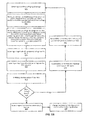
- FIG. 6B is a flowchart illustrating another embodiment of a method of controlling a dual-fed induction generator (DFIG) during a high-voltage grid event.
- DFIG dual-fed induction generator
- Embodiments of steps of the method described in FIG. 6 can be performed by one or more computing devices such as controller 202.
- a condition of high grid voltage is detected.
- An overvoltage can be a short-term or longer duration increase in the measured voltage of the electrical system over its nominal rating.
- the overvoltage may be 1%, 5% 10%, 50%, 150% or greater, and any values therebetween, of the measured voltage over the nominal voltage.
- a threshold can be set for the overvoltage above which a high-voltage grid event is signaled.
- an output of a closed-loop portion of the rotor current regulator is set to a fixed value.
- the fixed value is zero or approximately zero.
- the predictive feed-forward path as described above is relied on as a convenient means of setting the generator internal voltage according to control objectives, as described above.
- a condition of high dc voltage, or a condition that will soon lead to high dc voltage condition such as, for example, high ac voltage, is detected and the rotor torque producing current command is reduced to approximately zero. In one aspect, this can be done by overriding the rotor current command after the normal logic flow, or by using the existing control structure and reducing the torque command. A combination may be used to achieve rapid response followed by smooth transition.
- the magnitude of the internal voltage on the generator is lowered. Generally, this can be accomplished by reducing air-gap flux in the generator. In one aspect, this is performed by moving the rotor flux producing (e.g., y-axis) command to the under excited region. Use of the existing feed-forward path is a means to set this current command in a manner that can prevent overcurrent blocking. The logic in the final rotor gating calculation can limit the voltage request to keep the rotor converter within its linear control range.
- the magnitude of converter voltage on the line converter is lowered. In one aspect, this is performed by moving the line converter flux producing current command, while limiting the command so that overcurrent blocking does not occur.
- crowbar action may be inhibited for electrical conditions for which the electrical system can continue without damage. In one aspect, crowbar action is blocked. In other aspects, crowbar action can be available but de-sensitized as crowbar action may still be prudent if the stress levels become too high, as a means to reduce the extent of possible damage to electrical components.
- step 622 If it is determined that the condition is a high-voltage ride through (HVRT) event, then the process goes to step 622 where the DFIG, converters and electrical system are controlled as described above or in accordance with U.S. Patent Publication U.S. 20120133343 Al (application serial no. 13/323309 ) filed December 12, 2011, which is fully incorporated by reference and made a part hereof.
- step 624 Following the above-described control response to a high-voltage grid event, should the grid return to a condition where there remains a viable electrical connection between the wind turbine and the grid, then the process goes to step 624 and control transitions back to normal mode.
- step 620 detect resumption of grid connection, with a grid voltage within the capability of the wind turbine. This involves at least a measure of grid voltage at the wind turbine. It may also involve measurements of the current flowing out of the wind turbine; (2) precondition upstream regulators as appropriate to provide a bumpless transition to normal control; and (3) switch (back) to normal control mode. The process then returns to step 608 to monitor for a high grid voltage.
- step 620 determine whether the event is a ride-through event or not generally involved determining whether the DFIG remains connected to the grid, or not.
- Another way of detecting that grid connections have been lost includes special monitoring functions enacted by the high-voltage condition, e.g. increasing the sensitivity of existing functions such as frequency and voltage deviations. And yet another way of detecting loss of grid connections includes receiving a signal from an external device that knows status of the grid connections. If it is determined at step 620 that the grid connection has been lost, then the process goes to step 626.
- step 626 once loss of grid connections is determined, then a command is issued to open the wind turbine circuit breaker; the status of wind turbine circuit breaker is determined after issuing the open command; and after it is determined that the wind turbine circuit breaker has opened, gating the converters is stopped as part of an orderly shutdown process.
- the torque producing (e.g., x-axis) current command can be changed to a motoring direction to further remove energy from the electrical system including the DFIG, dc link (including any capacitors), line-side converter, rotor side converter, any remaining grid, and the like.
- the converters are gated following the above strategy until the wind turbine circuit breaker clears the connection to the remaining portion of the grid.
- the above-described mode of operation remains in effect until either the grid conditions are determined to be in a connected mode where ride-through is possible, or a decision is made to stop the wind turbine.
- a protective action is requested in any mode of wind turbine operation, then the process as described in the exemplary flowchart of FIG. 7 is performed for controlling wind turbine electrical components when opening a system breaker associated with a DFIG upon detection of a condition requiring shutdown. Steps of the process shown in FIG. 7 can be performed by a computing device such as controller 202.
- a computing device such as controller 202.
- an abnormal operating condition is detected in the electrical system that requires shutdown of the DFIG and con/or converters.
- a command is issued to open wind turbine circuit breaker 214. This command can be issued based on any operational condition of the wind turbine, converters, and the like.
- gating is continued during and after issuing the command to open the wind turbine circuit breaker 214.
- Gating refers to causing electronic switches such as IGBTs and the like to fire or go to a conducting state for at least as long as they receive the gating signal.
- the status of wind turbine circuit breaker is determined after issuing the open command.
- gating the converters is stopped as part of an orderly shutdown process. If, at step 706, it is determined that the wind turbine circuit breaker has not opened, the process returns to step 704 and gating continues until the breaker opens or the trip command is rescinded.
- One benefit of continuing to gate the converters after the trip signal is issued is to allow the converters and generator to reduce the ac voltage that can be harmful to converter and turbine components.
- embodiments of the present invention may be configured as a system, method, or a computer program product. Accordingly, embodiments of the present invention may be comprised of various means including entirely of hardware, entirely of software, or any combination of software and hardware. Furthermore, embodiments of the present invention may take the form of a computer program product on a computer-readable storage medium having computer-readable program instructions (e.g., computer software) embodied in the storage medium. Any suitable non-transitory computer-readable storage medium may be utilized including hard disks, CD-ROMs, optical storage devices, or magnetic storage devices.
- These computer program instructions may also be stored in a non-transitory computer-readable memory that can direct a computer or other programmable data processing apparatus (e.g., processor(s) 62 of FIG. 3 ) to function in a particular manner, such that the instructions stored in the computer-readable memory produce an article of manufacture including computer-readable instructions for implementing the function specified in the flowchart block or blocks.
- the computer program instructions may also be loaded onto a computer or other programmable data processing apparatus to cause a series of operational steps to be performed on the computer or other programmable apparatus to produce a computer-implemented process such that the instructions that execute on the computer or other programmable apparatus provide steps for implementing the functions specified in the flowchart block or blocks.
- blocks of the block diagrams and flowchart illustrations support combinations of means for performing the specified functions, combinations of steps for performing the specified functions and program instruction means for performing the specified functions. It will also be understood that each block of the block diagrams and flowchart illustrations, and combinations of blocks in the block diagrams and flowchart illustrations, can be implemented by special purpose hardware-based computer systems that perform the specified functions or steps, or combinations of special purpose hardware and computer instructions.
Applications Claiming Priority (1)
| Application Number | Priority Date | Filing Date | Title |
|---|---|---|---|
| US13/600,730 US9450415B2 (en) | 2012-08-31 | 2012-08-31 | System and method for controlling a dual-fed induction generator in response to high-voltage grid events |
Publications (3)
| Publication Number | Publication Date |
|---|---|
| EP2704309A2 true EP2704309A2 (de) | 2014-03-05 |
| EP2704309A3 EP2704309A3 (de) | 2017-08-23 |
| EP2704309B1 EP2704309B1 (de) | 2022-06-22 |
Family
ID=49000862
Family Applications (1)
| Application Number | Title | Priority Date | Filing Date |
|---|---|---|---|
| EP13181279.4A Active EP2704309B1 (de) | 2012-08-31 | 2013-08-22 | System und Verfahren zur Steuerung eines doppelt gespeisten Induktionsgenerators als Reaktion auf Hochspannungsgitterereignisse |
Country Status (7)
| Country | Link |
|---|---|
| US (1) | US9450415B2 (de) |
| EP (1) | EP2704309B1 (de) |
| CN (1) | CN103683318B (de) |
| BR (1) | BR102013021844B1 (de) |
| CA (1) | CA2824204C (de) |
| DK (1) | DK2704309T3 (de) |
| ES (1) | ES2926708T3 (de) |
Cited By (5)
| Publication number | Priority date | Publication date | Assignee | Title |
|---|---|---|---|---|
| WO2017207863A1 (en) * | 2016-06-01 | 2017-12-07 | Wärtsilä Finland Oy | An electric power plant and a method and a system for controlling the same |
| CN111106630A (zh) * | 2019-12-31 | 2020-05-05 | 国网江西省电力有限公司电力科学研究院 | 一种调相机参与提升双馈风机高电压穿越能力的控制方法 |
| EP3654521A1 (de) * | 2018-11-16 | 2020-05-20 | General Electric Company | System und verfahren zur verringerung der überspannung auf eines gleichspannungszwischenkreises eines stromrichters |
| EP3736937A1 (de) * | 2019-05-10 | 2020-11-11 | MARICI Holdings The Netherlands B.V. | Verfahren und system zur steuerung des stromexports |
| EP3278447B1 (de) | 2015-04-01 | 2022-02-23 | Vestas Wind Systems A/S | Verfahren zur handhabung eines überspannungsdurchfahrtereignisses und doppeltgespeister induktionsgenerator |
Families Citing this family (20)
| Publication number | Priority date | Publication date | Assignee | Title |
|---|---|---|---|---|
| US20150094973A1 (en) * | 2013-10-02 | 2015-04-02 | Vanguard Instruments Company, Inc. | System for measuring excitation characteristics of magnetic assemblies using direct current |
| KR20150130154A (ko) * | 2014-05-13 | 2015-11-23 | 엘에스산전 주식회사 | 고전압 직류 송전 시스템 제어 장치 |
| US9973123B2 (en) * | 2016-03-16 | 2018-05-15 | General Electric Company | System and method for controlling a generator |
| US10523088B2 (en) | 2017-04-24 | 2019-12-31 | General Electric Company | Energy storage system for doubly fed induction generator |
| US10519933B2 (en) * | 2017-04-24 | 2019-12-31 | General Electric Company | Method of operating a wind turbine system including an energy storage system |
| US10587121B2 (en) * | 2017-05-23 | 2020-03-10 | General Electric Company | Electrical power systems and subsystems |
| US10570882B2 (en) * | 2017-11-13 | 2020-02-25 | General Electric Company | Dynamic active and reactive power capability for wind farms |
| EP3514910A1 (de) * | 2018-01-19 | 2019-07-24 | Nordex Energy GmbH | Verfahren zum betrieb einer windenergieanlage |
| SG10201903086XA (en) * | 2018-04-05 | 2019-11-28 | Univ Nanyang Tech | Dual Voltage And Current Loop Linearization Control and Voltage Balancing Control For Solid State Transformer |
| US10615727B2 (en) * | 2018-08-27 | 2020-04-07 | General Electric Company | Dynamic brake circuit assembly for a wind turbine |
| US10865773B1 (en) * | 2019-05-22 | 2020-12-15 | General Electric Company | System and method for mitigating flicker in a power grid from a wind turbine power system |
| US10868482B1 (en) | 2019-05-28 | 2020-12-15 | General Electric Company | Dual-frequency filter for distinguishing between different types of grid events |
| CN111211579B (zh) * | 2020-01-20 | 2021-09-21 | 四川大学 | 一种基于转子串限流电阻实现高电压穿越的方法和装置 |
| CN111371366B (zh) * | 2020-03-16 | 2021-10-12 | 湖南中聚福能源科技有限公司 | 一种变频水力发电系统模型预测电流控制方法、系统及介质 |
| US11486360B2 (en) | 2020-04-10 | 2022-11-01 | General Electric Company | System and method for controlling wind turbine converters during high voltage ride through events |
| US11530685B2 (en) | 2020-08-20 | 2022-12-20 | General Electric Company | System and method for managing output flicker generated by a wind farm |
| US11506173B2 (en) * | 2020-12-07 | 2022-11-22 | General Electric Company | System and method for providing grid-forming control for a double-fed wind turbine generator using virtual impedance |
| US11486355B2 (en) * | 2020-12-31 | 2022-11-01 | General Electric Company | Method for operating doubly-fed wind turbine generator as a virtual synchronous machine to provide grid-forming control thereof |
| US20230049606A1 (en) * | 2021-08-10 | 2023-02-16 | General Electric Company | System and method for controlling an electrical power system using a dynamic regulator maximum limit |
| CN114243763B (zh) * | 2021-11-29 | 2024-03-15 | 国网北京市电力公司 | 智能电网的孤岛事件检测方法、装置、存储介质及设备 |
Citations (3)
| Publication number | Priority date | Publication date | Assignee | Title |
|---|---|---|---|---|
| US6921985B2 (en) | 2003-01-24 | 2005-07-26 | General Electric Company | Low voltage ride through for wind turbine generators |
| US7321221B2 (en) | 2002-07-17 | 2008-01-22 | General Electric Company | Method for operating a wind power plant and method for operating it |
| US20120133343A1 (en) | 2011-12-12 | 2012-05-31 | General Electric Company | Wind turbine having a high-voltage ride through (hvrt) mode |
Family Cites Families (6)
| Publication number | Priority date | Publication date | Assignee | Title |
|---|---|---|---|---|
| US7411309B2 (en) * | 2003-05-02 | 2008-08-12 | Xantrex Technology Inc. | Control system for doubly fed induction generator |
| EP1499009B1 (de) * | 2003-07-15 | 2007-10-31 | Gamesa Innovation & Technology, S.L. Unipersonal | Steuer- und Schutzgerät für ein doppelgespeistes Induktionsgeneratorsystem |
| US7408268B1 (en) | 2005-08-04 | 2008-08-05 | Magnetek, S.P.A. | Anti-islanding method and system for distributed power generation systems |
| US7884492B2 (en) * | 2007-11-13 | 2011-02-08 | General Electric Company | Methods and systems for wind turbine generators |
| US8310074B2 (en) * | 2009-10-30 | 2012-11-13 | General Electric Company | Method and apparatus for generating power in a wind turbine |
| US8907510B2 (en) * | 2012-03-09 | 2014-12-09 | General Electric Company | Method and systems for operating a wind turbine |
-
2012
- 2012-08-31 US US13/600,730 patent/US9450415B2/en active Active
-
2013
- 2013-08-22 DK DK13181279.4T patent/DK2704309T3/da active
- 2013-08-22 EP EP13181279.4A patent/EP2704309B1/de active Active
- 2013-08-22 ES ES13181279T patent/ES2926708T3/es active Active
- 2013-08-22 CA CA2824204A patent/CA2824204C/en active Active
- 2013-08-27 BR BR102013021844-8A patent/BR102013021844B1/pt active IP Right Grant
- 2013-08-30 CN CN201310386981.3A patent/CN103683318B/zh active Active
Patent Citations (3)
| Publication number | Priority date | Publication date | Assignee | Title |
|---|---|---|---|---|
| US7321221B2 (en) | 2002-07-17 | 2008-01-22 | General Electric Company | Method for operating a wind power plant and method for operating it |
| US6921985B2 (en) | 2003-01-24 | 2005-07-26 | General Electric Company | Low voltage ride through for wind turbine generators |
| US20120133343A1 (en) | 2011-12-12 | 2012-05-31 | General Electric Company | Wind turbine having a high-voltage ride through (hvrt) mode |
Cited By (8)
| Publication number | Priority date | Publication date | Assignee | Title |
|---|---|---|---|---|
| EP3278447B1 (de) | 2015-04-01 | 2022-02-23 | Vestas Wind Systems A/S | Verfahren zur handhabung eines überspannungsdurchfahrtereignisses und doppeltgespeister induktionsgenerator |
| WO2017207863A1 (en) * | 2016-06-01 | 2017-12-07 | Wärtsilä Finland Oy | An electric power plant and a method and a system for controlling the same |
| KR20190006572A (ko) * | 2016-06-01 | 2019-01-18 | 바르실라 핀랜드 오이 | 전력 플랜트 및 그것을 제어하기 위한 방법 및 시스템 |
| EP3654521A1 (de) * | 2018-11-16 | 2020-05-20 | General Electric Company | System und verfahren zur verringerung der überspannung auf eines gleichspannungszwischenkreises eines stromrichters |
| US11114839B2 (en) | 2018-11-16 | 2021-09-07 | General Electric Company | System and method for mitigating overvoltage on a DC link of a power converter |
| EP3736937A1 (de) * | 2019-05-10 | 2020-11-11 | MARICI Holdings The Netherlands B.V. | Verfahren und system zur steuerung des stromexports |
| CN111106630A (zh) * | 2019-12-31 | 2020-05-05 | 国网江西省电力有限公司电力科学研究院 | 一种调相机参与提升双馈风机高电压穿越能力的控制方法 |
| CN111106630B (zh) * | 2019-12-31 | 2023-03-10 | 国网江西省电力有限公司电力科学研究院 | 一种调相机参与提升双馈风机高电压穿越能力的控制方法 |
Also Published As
| Publication number | Publication date |
|---|---|
| CA2824204A1 (en) | 2014-02-28 |
| US20140062424A1 (en) | 2014-03-06 |
| EP2704309A3 (de) | 2017-08-23 |
| CN103683318B (zh) | 2017-04-19 |
| BR102013021844B1 (pt) | 2020-12-15 |
| BR102013021844A2 (pt) | 2016-09-27 |
| DK2704309T3 (da) | 2022-09-12 |
| US9450415B2 (en) | 2016-09-20 |
| CA2824204C (en) | 2018-07-03 |
| CN103683318A (zh) | 2014-03-26 |
| EP2704309B1 (de) | 2022-06-22 |
| ES2926708T3 (es) | 2022-10-27 |
Similar Documents
| Publication | Publication Date | Title |
|---|---|---|
| EP2704309B1 (de) | System und Verfahren zur Steuerung eines doppelt gespeisten Induktionsgenerators als Reaktion auf Hochspannungsgitterereignisse | |
| US8664788B1 (en) | Method and systems for operating a wind turbine using dynamic braking in response to a grid event | |
| US20150311696A1 (en) | System and method for protecting electrical machines | |
| EP1914877B2 (de) | Vorrichtung zum Betreiben elektrischer Geräte | |
| EP2866323B1 (de) | Zusätzliches Stromversorgungssystem und Verfahren zur Regulierung von Spannungen davon | |
| EP2779351A2 (de) | Verfahren und Vorrichtung für die Erkennung von Inselbildung für Einspeiseumrichter | |
| US8854845B2 (en) | System and method of over-voltage protection | |
| WO2016018982A1 (en) | System and method for controlling a power output of a wind turbine generator | |
| US20150263508A1 (en) | System and method for detecting islanding of electrical machines and protecting same | |
| EP3745588B1 (de) | Doppelfrequenzfilter zur unterscheidung zwischen verschiedenen arten von netzereignissen | |
| US11549493B2 (en) | System and method for frequency filtering of a renewable energy power system | |
| WO2023041959A1 (en) | System and method for controlling a harmonic filter bank of a renewable energy power system | |
| WO2024091249A1 (en) | System and method for extending the operating speed threshold of a grid-forming inverter-based resource | |
| AU2011203021A1 (en) | Dynamic Electric Brake For A Variable Speed Wind Turbine Having An Exciter Machine and a Power Converter Not Connected To The Grid |
Legal Events
| Date | Code | Title | Description |
|---|---|---|---|
| AK | Designated contracting states |
Kind code of ref document: A2 Designated state(s): AL AT BE BG CH CY CZ DE DK EE ES FI FR GB GR HR HU IE IS IT LI LT LU LV MC MK MT NL NO PL PT RO RS SE SI SK SM TR |
|
| AX | Request for extension of the european patent |
Extension state: BA ME |
|
| PUAI | Public reference made under article 153(3) epc to a published international application that has entered the european phase |
Free format text: ORIGINAL CODE: 0009012 |
|
| PUAL | Search report despatched |
Free format text: ORIGINAL CODE: 0009013 |
|
| AK | Designated contracting states |
Kind code of ref document: A3 Designated state(s): AL AT BE BG CH CY CZ DE DK EE ES FI FR GB GR HR HU IE IS IT LI LT LU LV MC MK MT NL NO PL PT RO RS SE SI SK SM TR |
|
| AX | Request for extension of the european patent |
Extension state: BA ME |
|
| RIC1 | Information provided on ipc code assigned before grant |
Ipc: H02J 3/38 20060101ALI20170720BHEP Ipc: H02P 9/10 20060101ALI20170720BHEP Ipc: H02P 9/00 20060101AFI20170720BHEP |
|
| STAA | Information on the status of an ep patent application or granted ep patent |
Free format text: STATUS: REQUEST FOR EXAMINATION WAS MADE |
|
| 17P | Request for examination filed |
Effective date: 20180223 |
|
| RBV | Designated contracting states (corrected) |
Designated state(s): AL AT BE BG CH CY CZ DE DK EE ES FI FR GB GR HR HU IE IS IT LI LT LU LV MC MK MT NL NO PL PT RO RS SE SI SK SM TR |
|
| STAA | Information on the status of an ep patent application or granted ep patent |
Free format text: STATUS: EXAMINATION IS IN PROGRESS |
|
| 17Q | First examination report despatched |
Effective date: 20200504 |
|
| STAA | Information on the status of an ep patent application or granted ep patent |
Free format text: STATUS: EXAMINATION IS IN PROGRESS |
|
| GRAP | Despatch of communication of intention to grant a patent |
Free format text: ORIGINAL CODE: EPIDOSNIGR1 |
|
| STAA | Information on the status of an ep patent application or granted ep patent |
Free format text: STATUS: GRANT OF PATENT IS INTENDED |
|
| INTG | Intention to grant announced |
Effective date: 20220207 |
|
| GRAS | Grant fee paid |
Free format text: ORIGINAL CODE: EPIDOSNIGR3 |
|
| GRAA | (expected) grant |
Free format text: ORIGINAL CODE: 0009210 |
|
| STAA | Information on the status of an ep patent application or granted ep patent |
Free format text: STATUS: THE PATENT HAS BEEN GRANTED |
|
| AK | Designated contracting states |
Kind code of ref document: B1 Designated state(s): AL AT BE BG CH CY CZ DE DK EE ES FI FR GB GR HR HU IE IS IT LI LT LU LV MC MK MT NL NO PL PT RO RS SE SI SK SM TR |
|
| REG | Reference to a national code |
Ref country code: GB Ref legal event code: FG4D |
|
| REG | Reference to a national code |
Ref country code: CH Ref legal event code: EP |
|
| REG | Reference to a national code |
Ref country code: DE Ref legal event code: R096 Ref document number: 602013081895 Country of ref document: DE |
|
| REG | Reference to a national code |
Ref country code: AT Ref legal event code: REF Ref document number: 1500440 Country of ref document: AT Kind code of ref document: T Effective date: 20220715 |
|
| REG | Reference to a national code |
Ref country code: IE Ref legal event code: FG4D |
|
| REG | Reference to a national code |
Ref country code: DK Ref legal event code: T3 Effective date: 20220908 |
|
| REG | Reference to a national code |
Ref country code: LT Ref legal event code: MG9D |
|
| REG | Reference to a national code |
Ref country code: NL Ref legal event code: MP Effective date: 20220622 |
|
| REG | Reference to a national code |
Ref country code: ES Ref legal event code: FG2A Ref document number: 2926708 Country of ref document: ES Kind code of ref document: T3 Effective date: 20221027 |
|
| PG25 | Lapsed in a contracting state [announced via postgrant information from national office to epo] |
Ref country code: SE Free format text: LAPSE BECAUSE OF FAILURE TO SUBMIT A TRANSLATION OF THE DESCRIPTION OR TO PAY THE FEE WITHIN THE PRESCRIBED TIME-LIMIT Effective date: 20220622 Ref country code: NO Free format text: LAPSE BECAUSE OF FAILURE TO SUBMIT A TRANSLATION OF THE DESCRIPTION OR TO PAY THE FEE WITHIN THE PRESCRIBED TIME-LIMIT Effective date: 20220922 Ref country code: LT Free format text: LAPSE BECAUSE OF FAILURE TO SUBMIT A TRANSLATION OF THE DESCRIPTION OR TO PAY THE FEE WITHIN THE PRESCRIBED TIME-LIMIT Effective date: 20220622 Ref country code: HR Free format text: LAPSE BECAUSE OF FAILURE TO SUBMIT A TRANSLATION OF THE DESCRIPTION OR TO PAY THE FEE WITHIN THE PRESCRIBED TIME-LIMIT Effective date: 20220622 Ref country code: GR Free format text: LAPSE BECAUSE OF FAILURE TO SUBMIT A TRANSLATION OF THE DESCRIPTION OR TO PAY THE FEE WITHIN THE PRESCRIBED TIME-LIMIT Effective date: 20220923 Ref country code: FI Free format text: LAPSE BECAUSE OF FAILURE TO SUBMIT A TRANSLATION OF THE DESCRIPTION OR TO PAY THE FEE WITHIN THE PRESCRIBED TIME-LIMIT Effective date: 20220622 Ref country code: BG Free format text: LAPSE BECAUSE OF FAILURE TO SUBMIT A TRANSLATION OF THE DESCRIPTION OR TO PAY THE FEE WITHIN THE PRESCRIBED TIME-LIMIT Effective date: 20220922 |
|
| REG | Reference to a national code |
Ref country code: AT Ref legal event code: MK05 Ref document number: 1500440 Country of ref document: AT Kind code of ref document: T Effective date: 20220622 |
|
| PG25 | Lapsed in a contracting state [announced via postgrant information from national office to epo] |
Ref country code: RS Free format text: LAPSE BECAUSE OF FAILURE TO SUBMIT A TRANSLATION OF THE DESCRIPTION OR TO PAY THE FEE WITHIN THE PRESCRIBED TIME-LIMIT Effective date: 20220622 Ref country code: LV Free format text: LAPSE BECAUSE OF FAILURE TO SUBMIT A TRANSLATION OF THE DESCRIPTION OR TO PAY THE FEE WITHIN THE PRESCRIBED TIME-LIMIT Effective date: 20220622 |
|
| PG25 | Lapsed in a contracting state [announced via postgrant information from national office to epo] |
Ref country code: NL Free format text: LAPSE BECAUSE OF FAILURE TO SUBMIT A TRANSLATION OF THE DESCRIPTION OR TO PAY THE FEE WITHIN THE PRESCRIBED TIME-LIMIT Effective date: 20220622 |
|
| PG25 | Lapsed in a contracting state [announced via postgrant information from national office to epo] |
Ref country code: SM Free format text: LAPSE BECAUSE OF FAILURE TO SUBMIT A TRANSLATION OF THE DESCRIPTION OR TO PAY THE FEE WITHIN THE PRESCRIBED TIME-LIMIT Effective date: 20220622 Ref country code: SK Free format text: LAPSE BECAUSE OF FAILURE TO SUBMIT A TRANSLATION OF THE DESCRIPTION OR TO PAY THE FEE WITHIN THE PRESCRIBED TIME-LIMIT Effective date: 20220622 Ref country code: RO Free format text: LAPSE BECAUSE OF FAILURE TO SUBMIT A TRANSLATION OF THE DESCRIPTION OR TO PAY THE FEE WITHIN THE PRESCRIBED TIME-LIMIT Effective date: 20220622 Ref country code: PT Free format text: LAPSE BECAUSE OF FAILURE TO SUBMIT A TRANSLATION OF THE DESCRIPTION OR TO PAY THE FEE WITHIN THE PRESCRIBED TIME-LIMIT Effective date: 20221024 Ref country code: EE Free format text: LAPSE BECAUSE OF FAILURE TO SUBMIT A TRANSLATION OF THE DESCRIPTION OR TO PAY THE FEE WITHIN THE PRESCRIBED TIME-LIMIT Effective date: 20220622 Ref country code: CZ Free format text: LAPSE BECAUSE OF FAILURE TO SUBMIT A TRANSLATION OF THE DESCRIPTION OR TO PAY THE FEE WITHIN THE PRESCRIBED TIME-LIMIT Effective date: 20220622 Ref country code: AT Free format text: LAPSE BECAUSE OF FAILURE TO SUBMIT A TRANSLATION OF THE DESCRIPTION OR TO PAY THE FEE WITHIN THE PRESCRIBED TIME-LIMIT Effective date: 20220622 |
|
| PG25 | Lapsed in a contracting state [announced via postgrant information from national office to epo] |
Ref country code: PL Free format text: LAPSE BECAUSE OF FAILURE TO SUBMIT A TRANSLATION OF THE DESCRIPTION OR TO PAY THE FEE WITHIN THE PRESCRIBED TIME-LIMIT Effective date: 20220622 Ref country code: IS Free format text: LAPSE BECAUSE OF FAILURE TO SUBMIT A TRANSLATION OF THE DESCRIPTION OR TO PAY THE FEE WITHIN THE PRESCRIBED TIME-LIMIT Effective date: 20221022 |
|
| REG | Reference to a national code |
Ref country code: DE Ref legal event code: R097 Ref document number: 602013081895 Country of ref document: DE |
|
| PG25 | Lapsed in a contracting state [announced via postgrant information from national office to epo] |
Ref country code: MC Free format text: LAPSE BECAUSE OF FAILURE TO SUBMIT A TRANSLATION OF THE DESCRIPTION OR TO PAY THE FEE WITHIN THE PRESCRIBED TIME-LIMIT Effective date: 20220622 Ref country code: AL Free format text: LAPSE BECAUSE OF FAILURE TO SUBMIT A TRANSLATION OF THE DESCRIPTION OR TO PAY THE FEE WITHIN THE PRESCRIBED TIME-LIMIT Effective date: 20220622 |
|
| REG | Reference to a national code |
Ref country code: CH Ref legal event code: PL |
|
| PG25 | Lapsed in a contracting state [announced via postgrant information from national office to epo] |
Ref country code: LU Free format text: LAPSE BECAUSE OF NON-PAYMENT OF DUE FEES Effective date: 20220822 Ref country code: LI Free format text: LAPSE BECAUSE OF NON-PAYMENT OF DUE FEES Effective date: 20220831 Ref country code: CH Free format text: LAPSE BECAUSE OF NON-PAYMENT OF DUE FEES Effective date: 20220831 |
|
| PLBE | No opposition filed within time limit |
Free format text: ORIGINAL CODE: 0009261 |
|
| STAA | Information on the status of an ep patent application or granted ep patent |
Free format text: STATUS: NO OPPOSITION FILED WITHIN TIME LIMIT |
|
| REG | Reference to a national code |
Ref country code: BE Ref legal event code: MM Effective date: 20220831 |
|
| GBPC | Gb: european patent ceased through non-payment of renewal fee |
Effective date: 20220922 |
|
| 26N | No opposition filed |
Effective date: 20230323 |
|
| P01 | Opt-out of the competence of the unified patent court (upc) registered |
Effective date: 20230530 |
|
| PG25 | Lapsed in a contracting state [announced via postgrant information from national office to epo] |
Ref country code: IE Free format text: LAPSE BECAUSE OF NON-PAYMENT OF DUE FEES Effective date: 20220822 Ref country code: FR Free format text: LAPSE BECAUSE OF NON-PAYMENT OF DUE FEES Effective date: 20220822 |
|
| PG25 | Lapsed in a contracting state [announced via postgrant information from national office to epo] |
Ref country code: SI Free format text: LAPSE BECAUSE OF FAILURE TO SUBMIT A TRANSLATION OF THE DESCRIPTION OR TO PAY THE FEE WITHIN THE PRESCRIBED TIME-LIMIT Effective date: 20220622 |
|
| PG25 | Lapsed in a contracting state [announced via postgrant information from national office to epo] |
Ref country code: BE Free format text: LAPSE BECAUSE OF NON-PAYMENT OF DUE FEES Effective date: 20220831 |
|
| PG25 | Lapsed in a contracting state [announced via postgrant information from national office to epo] |
Ref country code: GB Free format text: LAPSE BECAUSE OF NON-PAYMENT OF DUE FEES Effective date: 20220922 |
|
| PGFP | Annual fee paid to national office [announced via postgrant information from national office to epo] |
Ref country code: ES Payment date: 20230901 Year of fee payment: 11 |
|
| PGFP | Annual fee paid to national office [announced via postgrant information from national office to epo] |
Ref country code: DK Payment date: 20230721 Year of fee payment: 11 Ref country code: DE Payment date: 20230720 Year of fee payment: 11 |
|
| REG | Reference to a national code |
Ref country code: DE Ref legal event code: R082 Ref document number: 602013081895 Country of ref document: DE Representative=s name: ZIMMERMANN & PARTNER PATENTANWAELTE MBB, DE Ref country code: DE Ref legal event code: R082 Ref document number: 602013081895 Country of ref document: DE Ref country code: DE Ref legal event code: R081 Ref document number: 602013081895 Country of ref document: DE Owner name: GENERAL ELECTRIC RENOVABLES ESPANA, S.L., ES Free format text: FORMER OWNER: GENERAL ELECTRIC COMPANY, SCHENECTADY, NY, US |
|
| PG25 | Lapsed in a contracting state [announced via postgrant information from national office to epo] |
Ref country code: IT Free format text: LAPSE BECAUSE OF FAILURE TO SUBMIT A TRANSLATION OF THE DESCRIPTION OR TO PAY THE FEE WITHIN THE PRESCRIBED TIME-LIMIT Effective date: 20220622 |
|
| REG | Reference to a national code |
Ref country code: DE Ref legal event code: R082 Ref document number: 602013081895 Country of ref document: DE Representative=s name: ZIMMERMANN & PARTNER PATENTANWAELTE MBB, DE |
|
| PG25 | Lapsed in a contracting state [announced via postgrant information from national office to epo] |
Ref country code: HU Free format text: LAPSE BECAUSE OF FAILURE TO SUBMIT A TRANSLATION OF THE DESCRIPTION OR TO PAY THE FEE WITHIN THE PRESCRIBED TIME-LIMIT; INVALID AB INITIO Effective date: 20130822 |
|
| PG25 | Lapsed in a contracting state [announced via postgrant information from national office to epo] |
Ref country code: CY Free format text: LAPSE BECAUSE OF FAILURE TO SUBMIT A TRANSLATION OF THE DESCRIPTION OR TO PAY THE FEE WITHIN THE PRESCRIBED TIME-LIMIT Effective date: 20220622 |