EP2704258A1 - Antenna and wireless terminal device - Google Patents
Antenna and wireless terminal device Download PDFInfo
- Publication number
- EP2704258A1 EP2704258A1 EP12871289.0A EP12871289A EP2704258A1 EP 2704258 A1 EP2704258 A1 EP 2704258A1 EP 12871289 A EP12871289 A EP 12871289A EP 2704258 A1 EP2704258 A1 EP 2704258A1
- Authority
- EP
- European Patent Office
- Prior art keywords
- antenna
- conductor
- terminal device
- wireless terminal
- antenna body
- Prior art date
- Legal status (The legal status is an assumption and is not a legal conclusion. Google has not performed a legal analysis and makes no representation as to the accuracy of the status listed.)
- Ceased
Links
Images


Classifications
-
- H—ELECTRICITY
- H01—ELECTRIC ELEMENTS
- H01Q—ANTENNAS, i.e. RADIO AERIALS
- H01Q9/00—Electrically-short antennas having dimensions not more than twice the operating wavelength and consisting of conductive active radiating elements
- H01Q9/04—Resonant antennas
- H01Q9/0407—Substantially flat resonant element parallel to ground plane, e.g. patch antenna
-
- H—ELECTRICITY
- H01—ELECTRIC ELEMENTS
- H01Q—ANTENNAS, i.e. RADIO AERIALS
- H01Q1/00—Details of, or arrangements associated with, antennas
- H01Q1/12—Supports; Mounting means
- H01Q1/22—Supports; Mounting means by structural association with other equipment or articles
- H01Q1/24—Supports; Mounting means by structural association with other equipment or articles with receiving set
- H01Q1/241—Supports; Mounting means by structural association with other equipment or articles with receiving set used in mobile communications, e.g. GSM
- H01Q1/242—Supports; Mounting means by structural association with other equipment or articles with receiving set used in mobile communications, e.g. GSM specially adapted for hand-held use
- H01Q1/243—Supports; Mounting means by structural association with other equipment or articles with receiving set used in mobile communications, e.g. GSM specially adapted for hand-held use with built-in antennas
-
- H—ELECTRICITY
- H01—ELECTRIC ELEMENTS
- H01Q—ANTENNAS, i.e. RADIO AERIALS
- H01Q1/00—Details of, or arrangements associated with, antennas
- H01Q1/12—Supports; Mounting means
- H01Q1/22—Supports; Mounting means by structural association with other equipment or articles
- H01Q1/24—Supports; Mounting means by structural association with other equipment or articles with receiving set
- H01Q1/241—Supports; Mounting means by structural association with other equipment or articles with receiving set used in mobile communications, e.g. GSM
- H01Q1/242—Supports; Mounting means by structural association with other equipment or articles with receiving set used in mobile communications, e.g. GSM specially adapted for hand-held use
- H01Q1/245—Supports; Mounting means by structural association with other equipment or articles with receiving set used in mobile communications, e.g. GSM specially adapted for hand-held use with means for shaping the antenna pattern, e.g. in order to protect user against rf exposure
-
- H—ELECTRICITY
- H01—ELECTRIC ELEMENTS
- H01Q—ANTENNAS, i.e. RADIO AERIALS
- H01Q7/00—Loop antennas with a substantially uniform current distribution around the loop and having a directional radiation pattern in a plane perpendicular to the plane of the loop
-
- H—ELECTRICITY
- H01—ELECTRIC ELEMENTS
- H01Q—ANTENNAS, i.e. RADIO AERIALS
- H01Q9/00—Electrically-short antennas having dimensions not more than twice the operating wavelength and consisting of conductive active radiating elements
- H01Q9/04—Resonant antennas
- H01Q9/16—Resonant antennas with feed intermediate between the extremities of the antenna, e.g. centre-fed dipole
- H01Q9/26—Resonant antennas with feed intermediate between the extremities of the antenna, e.g. centre-fed dipole with folded element or elements, the folded parts being spaced apart a small fraction of operating wavelength
- H01Q9/265—Open ring dipoles; Circular dipoles
Definitions
- Embodiments of the present invention relate to communications technologies, and in particular, to an antenna and a wireless terminal device.
- wireless terminal devices such as a tablet (Tablet) and a data card. While a user enjoys various conveniences brought by a wireless terminal device, the user also pays more and more attention to influence on human health caused by electromagnetic radiation generated by the wireless terminal device.
- a specific absorption rate (Specific Absorption Rate, SAR for short) has become one piece of content which is marked on product packages or specifications by wireless terminal device manufacturers from many countries and regions.
- a proximity sensor may be added near an antenna, so that when a wireless terminal device gets close to a human body, transmission power is reduced actively, so as to ensure the SAR performance of the wireless terminal device.
- the antenna ensures the SAR performance of the wireless terminal device
- the transmission power is reduced, so the wireless performance of the wireless terminal device is greatly reduced.
- Embodiments of the present invention provide an antenna and a wireless terminal device, so that while the SAR performance of a wireless terminal device is ensured, the wireless performance of the wireless terminal device is not affected.
- an antenna which includes a ring-shaped antenna body, where the inner side of the antenna body is connected to a first conductor through a conductor connecting part, so that current on the antenna body is dispersed to the first conductor, and the first conductor is encircled by the antenna body.
- the antenna further includes a gap, which passes through the conductor connecting part, the antenna body connected to the conductor connecting part and the first conductor connected to the conductor connecting part.
- the shape of the gap includes linear type, L shape or T shape.
- the antenna body and the first conductor are disposed in a folding way along a specified direction.
- the upper side of the antenna body is disposed with a second conductor, and a plane where the second conductor is located is parallel to a plane where the antenna body is located.
- a wireless terminal device which includes a printed circuit board (Printed Circuit Board, PCB for short) and the above antenna, where the PCB is connected to the antenna body.
- PCB printed Circuit Board
- the wireless terminal device in embodiments of the present invention may include but not limited to a tablet (Tablet) or a data card.
- An embodiment of the present invention provides an antenna, which may include a ring-shaped antenna body, where the inner side of the antenna body is connected to a first conductor through a conductor connecting part, and the first conductor is encircled by the antenna body.
- the antenna ensures the SAR performance of the wireless terminal device
- the wireless performance of the wireless terminal device is greatly reduced.
- the antenna may further include a gap, which passes through the conductor connecting part, the antenna body connected to the conductor connecting part and the first conductor connected to the conductor connecting part.
- the shape of the gap may include but not limited to linear type, L shape or T shape.
- the antenna body and the first conductor may be disposed in a folding way along a specified direction.
- the upper side of the antenna body may be further disposed with a second conductor.
- FIG. 1 is a schematic structural diagram of an antenna provided by an embodiment of the present invention.
- the antenna of this embodiment includes a ring-shaped antenna body 11, the inner side of the antenna body 11 is connected to a first conductor 12 through a conductor connecting part 13, and the first conductor 12 is encircled by the antenna body 11.
- the conductor connecting part 13 and the first conductor 12 may include but not limited to metal conductors such as copper or iron, or may further include nonmetal conductors such as carbon.
- the first conductor 12 can change the surface current distribution (namely, peak distribution) situation on the antenna body 11 through the conductor connecting part 13, and the distribution situation of the surface current on the antenna body 11 changes after the surface current passes through the first conductor 12, namely, the current on the antenna body 11 can be dispersed to the first conductor 12 through the conductor connecting part 13, so as to reduce the strength of the current on the antenna body 11, and especially reduce the strength of the current near the conductor connecting part 13 obviously.
- the SAR performance of the wireless terminal device is related to the distribution situation of the surface current on the antenna, for example, if the strength of the surface current is reduced, the SAR is reduced. Through the first conductor 12 which is connected to the inner side of the antenna body 11 through the conductor connecting part 13, the SAR performance of the wireless terminal device may be improved.
- the area of the first conductor 12 may be 50% to 90% of the area encircled by the antenna body 11.
- the current on the antenna body is enabled to be dispersed to the first conductor, which can avoid the problem that in the prior art, while the antenna ensures the SAR performance of the wireless terminal device, the wireless performance of the wireless terminal device is greatly reduced.
- FIG. 2 to FIG. 4 are schematic structural diagrams of an antenna provided by another embodiment of the present invention.
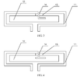
- the antenna provide by this embodiment may further include a gap 14, which passes through the conductor connecting part 13, the antenna body 11 connected to the conductor connecting part 13 and the first conductor 12 connected to the conductor connecting part.
- the shape of the gap may include but not limited to linear type (shown in FIG. 2 ), L shape (shown in FIG. 3 ) or T shape (shown in FIG. 4 ).
- the adjustment of an input impedance matching characteristic (namely, a matching degree of the input impedance and a system circuit of the antenna) of the antenna may be implemented by adjusting parameters such as length and width of the gap, thereby further improving the wireless performance of the antenna, for example: wireless sensitivity of the antenna.
- the antenna provided by the present invention may have a plurality of resonance frequency points, so the resonance frequency points of the antenna may be lowered by lengthening the gap, thereby improving the wireless sensitivity of the antenna.
- the antenna body 11 involved in this embodiment may also be the shape of other irregular rings, which is not limited in the embodiment of the present invention.
- the first conductor 12 involved in this embodiment is not necessarily the shape of rectangle, and may also be other shapes, for example: regular shapes such as trapezoid or parallelogram, or may also be irregular shapes, which is not limited in the embodiment of the present invention.
- the antenna body 11 and the first conductor 12 may further be disposed in a folding way along a specified direction (for example: a narrow side direction of the antenna), which can further reduce the volume of the antenna, as shown in FIG. 5 .
- the specified direction may be preset by manufacturers of the antenna, manufacturers of the wireless terminal where the antenna is located or users of the antenna according to the environment to which the antenna is applied (namely, the specification of the wireless terminal device where the antenna is located), and may be any directions.
- FIG. 6 is a schematic structural diagram of an antenna provided by another embodiment of the present invention.
- a second conductor 15 may be further disposed on a plane parallel to a plane where the antenna body 11 is located, so as to block a part of radiation of electromagnetic wave, and further improve the SAR performance of the wireless terminal device.
- the distance between the plane where the antenna body 11 is located and the plane where the second conductor 15 is located may range from 2 millimeters to one tenth of the wavelength of the electromagnetic wave corresponding to a resonance frequency of the antenna body.
- the second conductor 15 may be fixed on many places, for example: may be fixed on a housing of the wireless terminal device where the antenna is located, or may also be fixed on a printed circuit board (Printed Circuit Board, PCB for short) connected to the antenna, which is not limited in this embodiment.
- a printed circuit board Printed Circuit Board, PCB for short
- the second conductor 15 may include but not limited to metal conductors such as copper or iron, or may further include nonmetal conductors such as carbon.
- Another embodiment of the present invention further provides a wireless terminal device, which may include a printed circuit board (Printed Circuit Board, PCB for short) and the antenna provided by the above embodiments corresponding to FIG. 1 to FIG. 6 , where the PCB is connected to the antenna body.
- a wireless terminal device which may include a printed circuit board (Printed Circuit Board, PCB for short) and the antenna provided by the above embodiments corresponding to FIG. 1 to FIG. 6 , where the PCB is connected to the antenna body.
- PCB printed Circuit Board
Landscapes
- Engineering & Computer Science (AREA)
- Computer Networks & Wireless Communication (AREA)
- Support Of Aerials (AREA)
- Details Of Aerials (AREA)
- Aerials With Secondary Devices (AREA)
- Telephone Set Structure (AREA)
Abstract
Description
- This application claims priority to Chinese Patent Application No.
201210070698.5 - Embodiments of the present invention relate to communications technologies, and in particular, to an antenna and a wireless terminal device.
- With the development of wireless communication technologies, more and more wireless terminal devices appear, such as a tablet (Tablet) and a data card. While a user enjoys various conveniences brought by a wireless terminal device, the user also pays more and more attention to influence on human health caused by electromagnetic radiation generated by the wireless terminal device. As an indicator for measuring the electromagnetic radiation intensity of the wireless terminal device when the wireless terminal device is close to a human body, a specific absorption rate (Specific Absorption Rate, SAR for short) has become one piece of content which is marked on product packages or specifications by wireless terminal device manufacturers from many countries and regions. In the prior art, a proximity sensor may be added near an antenna, so that when a wireless terminal device gets close to a human body, transmission power is reduced actively, so as to ensure the SAR performance of the wireless terminal device.
- However, while the antenna ensures the SAR performance of the wireless terminal device, the transmission power is reduced, so the wireless performance of the wireless terminal device is greatly reduced.
- Embodiments of the present invention provide an antenna and a wireless terminal device, so that while the SAR performance of a wireless terminal device is ensured, the wireless performance of the wireless terminal device is not affected.
- In one aspect, an antenna is provided, which includes a ring-shaped antenna body, where the inner side of the antenna body is connected to a first conductor through a conductor connecting part, so that current on the antenna body is dispersed to the first conductor, and the first conductor is encircled by the antenna body.
- According to the above antenna, the antenna further includes a gap, which passes through the conductor connecting part, the antenna body connected to the conductor connecting part and the first conductor connected to the conductor connecting part.
- According to the above antenna, the shape of the gap includes linear type, L shape or T shape.
- According to the above antenna, the antenna body and the first conductor are disposed in a folding way along a specified direction.
- According to the above antenna, the upper side of the antenna body is disposed with a second conductor, and a plane where the second conductor is located is parallel to a plane where the antenna body is located.
- In another aspect, a wireless terminal device is provided, which includes a printed circuit board (Printed Circuit Board, PCB for short) and the above antenna, where the PCB is connected to the antenna body.
- It may be known from the above technical solutions that, in the embodiments of the present invention, through the first conductor connected to the inner side of the antenna body, the current on the antenna body is enabled to be dispersed to the first conductor, which can avoid the problem that in the prior art, while the antenna ensures the SAR performance of the wireless terminal device, the wireless performance of the wireless terminal device is greatly reduced. By adopting the technical solutions of the present invention, while the SAR performance of the wireless terminal device is ensured, the wireless performance of the wireless terminal device cannot be affected.
- To describe the technical solutions in the embodiments of the present invention or in the prior art more clearly, the following briefly introduces the accompanying drawings needed for describing the embodiments or the prior art. Apparently, the accompanying drawings in the following description show some embodiments of the present invention, and persons of ordinary skill in the art may still derive other drawings from these accompanying drawings without creative efforts.
-
FIG. 1 is a schematic structural diagram of an antenna according to an embodiment of the present invention; -
FIG. 2 is a schematic structural diagram of an antenna according to another embodiment of the present invention; -
FIG. 3 is a schematic structural diagram of an antenna according to another embodiment of the present invention; -
FIG. 4 is a schematic structural diagram of an antenna according to another embodiment of the present invention; -
FIG. 5 is a schematic structural diagram of an antenna according to another embodiment of the present invention; and -
FIG. 6 is a schematic structural diagram of an antenna according to another embodiment of the present invention. - To make the objectives, technical solutions, and advantages of the embodiments of the present invention more comprehensible, the following clearly and completely describes the technical solutions in the embodiments of the present invention with reference to the accompanying drawings in the embodiments of the present invention. Apparently, the described embodiments are merely a part rather than all of the embodiments of the present invention. All other embodiments obtained by persons of ordinary skill in the art based on the embodiments of the present invention without creative efforts shall fall within the protection scope of the present invention.
- The wireless terminal device in embodiments of the present invention may include but not limited to a tablet (Tablet) or a data card.
- An embodiment of the present invention provides an antenna, which may include a ring-shaped antenna body, where the inner side of the antenna body is connected to a first conductor through a conductor connecting part, and the first conductor is encircled by the antenna body. Through the first conductor connected to the inner side of the antenna body, the problem can be avoided that in the prior art, while the antenna ensures the SAR performance of the wireless terminal device, the wireless performance of the wireless terminal device is greatly reduced. By adopting the technical solutions of the present invention, while the SAR performance of the wireless terminal device is ensured, the wireless performance of the wireless terminal device cannot be affected.
- Optionally, the antenna may further include a gap, which passes through the conductor connecting part, the antenna body connected to the conductor connecting part and the first conductor connected to the conductor connecting part.
- Optionally, the shape of the gap may include but not limited to linear type, L shape or T shape.
- Optionally, the antenna body and the first conductor may be disposed in a folding way along a specified direction.
- Optionally, the upper side of the antenna body may be further disposed with a second conductor.
-
FIG. 1 is a schematic structural diagram of an antenna provided by an embodiment of the present invention. As shown inFIG. 1 , the antenna of this embodiment includes a ring-shaped antenna body 11, the inner side of theantenna body 11 is connected to afirst conductor 12 through aconductor connecting part 13, and thefirst conductor 12 is encircled by theantenna body 11. - In an optional implementation manner of this embodiment, the
conductor connecting part 13 and thefirst conductor 12 may include but not limited to metal conductors such as copper or iron, or may further include nonmetal conductors such as carbon. - The
first conductor 12 can change the surface current distribution (namely, peak distribution) situation on theantenna body 11 through theconductor connecting part 13, and the distribution situation of the surface current on theantenna body 11 changes after the surface current passes through thefirst conductor 12, namely, the current on theantenna body 11 can be dispersed to thefirst conductor 12 through theconductor connecting part 13, so as to reduce the strength of the current on theantenna body 11, and especially reduce the strength of the current near theconductor connecting part 13 obviously. The SAR performance of the wireless terminal device is related to the distribution situation of the surface current on the antenna, for example, if the strength of the surface current is reduced, the SAR is reduced. Through thefirst conductor 12 which is connected to the inner side of theantenna body 11 through theconductor connecting part 13, the SAR performance of the wireless terminal device may be improved. The area of thefirst conductor 12 may be 50% to 90% of the area encircled by theantenna body 11. - In this embodiment, through the first conductor connected to the inner side of the antenna body, the current on the antenna body is enabled to be dispersed to the first conductor, which can avoid the problem that in the prior art, while the antenna ensures the SAR performance of the wireless terminal device, the wireless performance of the wireless terminal device is greatly reduced. By adopting the technical solutions of the present invention, while the SAR performance of the wireless terminal device is ensured, the wireless performance of the wireless terminal device cannot be affected.
-
FIG. 2 to FIG. 4 are schematic structural diagrams of an antenna provided by another embodiment of the present invention. As shown inFIG. 2 to FIG. 4 , compared with the antenna provided by the embodiment corresponding toFIG. 1 , the antenna provide by this embodiment may further include agap 14, which passes through theconductor connecting part 13, theantenna body 11 connected to theconductor connecting part 13 and thefirst conductor 12 connected to the conductor connecting part. - Optionally, the shape of the gap may include but not limited to linear type (shown in
FIG. 2 ), L shape (shown inFIG. 3 ) or T shape (shown inFIG. 4 ). - In this embodiment, through the gap opened on the antenna, the adjustment of an input impedance matching characteristic (namely, a matching degree of the input impedance and a system circuit of the antenna) of the antenna may be implemented by adjusting parameters such as length and width of the gap, thereby further improving the wireless performance of the antenna, for example: wireless sensitivity of the antenna. In an optional implementation manner of this embodiment, the antenna provided by the present invention may have a plurality of resonance frequency points, so the resonance frequency points of the antenna may be lowered by lengthening the gap, thereby improving the wireless sensitivity of the antenna.
- It should be noted that: the
antenna body 11 involved in this embodiment may also be the shape of other irregular rings, which is not limited in the embodiment of the present invention. Thefirst conductor 12 involved in this embodiment is not necessarily the shape of rectangle, and may also be other shapes, for example: regular shapes such as trapezoid or parallelogram, or may also be irregular shapes, which is not limited in the embodiment of the present invention. - In an optional implementation manner of this embodiment, the
antenna body 11 and thefirst conductor 12 may further be disposed in a folding way along a specified direction (for example: a narrow side direction of the antenna), which can further reduce the volume of the antenna, as shown inFIG. 5 . The specified direction may be preset by manufacturers of the antenna, manufacturers of the wireless terminal where the antenna is located or users of the antenna according to the environment to which the antenna is applied (namely, the specification of the wireless terminal device where the antenna is located), and may be any directions. -
FIG. 6 is a schematic structural diagram of an antenna provided by another embodiment of the present invention. As shown inFIG. 6 , compared with the antenna provided by the embodiment corresponding toFIG. 1 , in the antenna provided by this embodiment, asecond conductor 15 may be further disposed on a plane parallel to a plane where theantenna body 11 is located, so as to block a part of radiation of electromagnetic wave, and further improve the SAR performance of the wireless terminal device. The distance between the plane where theantenna body 11 is located and the plane where thesecond conductor 15 is located may range from 2 millimeters to one tenth of the wavelength of the electromagnetic wave corresponding to a resonance frequency of the antenna body. It should be understood that: thesecond conductor 15 may be fixed on many places, for example: may be fixed on a housing of the wireless terminal device where the antenna is located, or may also be fixed on a printed circuit board (Printed Circuit Board, PCB for short) connected to the antenna, which is not limited in this embodiment. - In an optional implementation manner of this embodiment, the
second conductor 15 may include but not limited to metal conductors such as copper or iron, or may further include nonmetal conductors such as carbon. - Another embodiment of the present invention further provides a wireless terminal device, which may include a printed circuit board (Printed Circuit Board, PCB for short) and the antenna provided by the above embodiments corresponding to
FIG. 1 to FIG. 6 , where the PCB is connected to the antenna body. - In the foregoing embodiments, the description of each of the embodiments has respective focuses. For a part that is not described in detail in a certain embodiment, reference may be made to related descriptions in other embodiments.
- Finally, it should be noted that the foregoing embodiments are merely intended for describing the technical solutions of the present invention other than limiting the present invention. Although the present invention is described in detail with reference to the foregoing embodiments, persons of ordinary skill in the art should understand that they may still make modifications to the technical solution described in the foregoing embodiments or make equivalent replacements to some technical features thereof; without departing from the spirit and scope of the technical solution of the embodiments of the present invention.
Claims (8)
- An antenna, comprising a ring-shaped antenna body, wherein the inner side of the antenna body is connected to a first conductor through a conductor connecting part, so that current on the antenna body is dispersed to the first conductor, and the first conductor is encircled by the antenna body.
- The antenna according to claim 1, wherein the area of the first conductor is 50% to 90% of the area encircled by the antenna body.
- The antenna according to claim 1 or 2, wherein the antenna further comprises a gap, and the gap passes through the conductor connecting part and the antenna body connected to the conductor connecting part, and enters the first conductor connected to the conductor connecting part.
- The antenna according to claim 3, wherein the shape of the gap comprises a linear type, L shape or T shape.
- The antenna according to any one of claims 1 to 4, wherein the antenna body and the first conductor are disposed in a folding way along a specified direction.
- The antenna according to any one of claims 1 to 5, wherein a second conductor is disposed on a plane parallel to a plane where the antenna body is located.
- The antenna according to claim 6, wherein the distance between the plane where the antenna body is located and the plane where the second conductor is located ranges from 2 millimeters to one tenth of the wavelength of electromagnetic wave corresponding to a resonance frequency of the antenna body.
- A wireless terminal device, comprising a printed circuit board PCB and the antenna according to any one of claims 1 to 7, wherein the PCB is connected to the antenna body.
Applications Claiming Priority (2)
| Application Number | Priority Date | Filing Date | Title |
|---|---|---|---|
| CN201210070698.5A CN103311650B (en) | 2012-03-16 | 2012-03-16 | Antenna and wireless terminal device |
| PCT/CN2012/081222 WO2013135035A1 (en) | 2012-03-16 | 2012-09-11 | Antenna and wireless terminal device |
Publications (2)
| Publication Number | Publication Date |
|---|---|
| EP2704258A1 true EP2704258A1 (en) | 2014-03-05 |
| EP2704258A4 EP2704258A4 (en) | 2014-08-20 |
Family
ID=49136616
Family Applications (1)
| Application Number | Title | Priority Date | Filing Date |
|---|---|---|---|
| EP12871289.0A Ceased EP2704258A4 (en) | 2012-03-16 | 2012-09-11 | ANTENNA AND WIRELESS TERMINAL DEVICE |
Country Status (5)
| Country | Link |
|---|---|
| US (1) | US9287626B2 (en) |
| EP (1) | EP2704258A4 (en) |
| JP (1) | JP2014517646A (en) |
| CN (1) | CN103311650B (en) |
| WO (1) | WO2013135035A1 (en) |
Families Citing this family (4)
| Publication number | Priority date | Publication date | Assignee | Title |
|---|---|---|---|---|
| CN104466356A (en) * | 2013-09-23 | 2015-03-25 | 中兴通讯股份有限公司 | Antenna and terminal |
| US10171133B1 (en) | 2018-02-20 | 2019-01-01 | Automated Assembly Corporation | Transponder arrangement |
| US10476143B1 (en) * | 2018-09-26 | 2019-11-12 | Lear Corporation | Antenna for base station of wireless remote-control system |
| CN115548652B (en) * | 2022-09-30 | 2025-08-15 | 联想(北京)有限公司 | Antenna and electronic equipment |
Family Cites Families (20)
| Publication number | Priority date | Publication date | Assignee | Title |
|---|---|---|---|---|
| JP3511402B2 (en) * | 1994-08-05 | 2004-03-29 | アイシン精機株式会社 | Circularly polarized loop antenna |
| FR2783115B1 (en) * | 1998-09-09 | 2000-12-01 | Centre Nat Rech Scient | IMPROVED ANTENNA |
| JP2001156544A (en) * | 1999-12-01 | 2001-06-08 | Matsushita Electric Ind Co Ltd | Antenna device |
| US7017822B2 (en) * | 2001-02-15 | 2006-03-28 | Integral Technologies, Inc. | Low cost RFID antenna manufactured from conductive loaded resin-based materials |
| CN1379618A (en) * | 2001-04-07 | 2002-11-13 | 付国营 | Refractive antenna technique for mobile telephone, talkback set, etc |
| TW506163B (en) * | 2001-12-19 | 2002-10-11 | Ind Tech Res Inst | Planar inverted-F antenna |
| US6741214B1 (en) * | 2002-11-06 | 2004-05-25 | Centurion Wireless Technologies, Inc. | Planar Inverted-F-Antenna (PIFA) having a slotted radiating element providing global cellular and GPS-bluetooth frequency response |
| JP2004320571A (en) * | 2003-04-18 | 2004-11-11 | Mitsubishi Materials Corp | Portable equipment with RFID function |
| KR100594135B1 (en) | 2003-06-13 | 2006-06-28 | 삼성전자주식회사 | Loop antenna for portable terminal to reduce electromagnetic wave absorption |
| DE10347719B4 (en) * | 2003-06-25 | 2009-12-10 | Samsung Electro-Mechanics Co., Ltd., Suwon | Inner antenna for a mobile communication device |
| WO2005022684A2 (en) * | 2003-09-02 | 2005-03-10 | Integral Technologies, Inc. | Low cost rfid antenna manufactured from conductive loaded resin-based materials |
| US6879299B1 (en) | 2003-10-15 | 2005-04-12 | Uc-Logic Technology Corp. | Induction antenna loop for low-level digital tablets |
| TWM258432U (en) * | 2004-03-09 | 2005-03-01 | Hon Hai Prec Ind Co Ltd | Multi-band antenna |
| KR100597581B1 (en) * | 2004-11-05 | 2006-07-06 | 한국전자통신연구원 | Symmetrical Multiband Internal Antenna with Stubs |
| US7639194B2 (en) * | 2006-11-30 | 2009-12-29 | Auden Techno Corp. | Dual-band loop antenna |
| EP2385578B1 (en) * | 2007-03-19 | 2014-05-21 | BlackBerry Limited | Dual-band F-slot patch antenna |
| JP5114357B2 (en) | 2008-10-09 | 2013-01-09 | 株式会社日立製作所 | Wireless IC tag |
| JP2011030190A (en) * | 2009-06-24 | 2011-02-10 | Panasonic Corp | Antenna device and portable radio equipment provided with the same |
| US8477069B2 (en) * | 2009-08-21 | 2013-07-02 | Mediatek Inc,. | Portable electronic device and antenna thereof |
| CN102280700B (en) * | 2011-05-05 | 2014-06-18 | 电子科技大学 | Printing boardband terminal antenna |
-
2012
- 2012-03-16 CN CN201210070698.5A patent/CN103311650B/en active Active
- 2012-09-11 EP EP12871289.0A patent/EP2704258A4/en not_active Ceased
- 2012-09-11 WO PCT/CN2012/081222 patent/WO2013135035A1/en not_active Ceased
- 2012-09-11 JP JP2014516183A patent/JP2014517646A/en active Pending
-
2013
- 2013-12-12 US US14/104,590 patent/US9287626B2/en active Active
Also Published As
| Publication number | Publication date |
|---|---|
| WO2013135035A1 (en) | 2013-09-19 |
| JP2014517646A (en) | 2014-07-17 |
| EP2704258A4 (en) | 2014-08-20 |
| US20140104123A1 (en) | 2014-04-17 |
| US9287626B2 (en) | 2016-03-15 |
| CN103311650B (en) | 2016-08-24 |
| CN103311650A (en) | 2013-09-18 |
Similar Documents
| Publication | Publication Date | Title |
|---|---|---|
| CN102646861B (en) | Antenna with integrated proximity sensor for proximity-based radio-frequency power control | |
| US10126780B2 (en) | Slot antenna for a wearable device | |
| EP2835862B1 (en) | Antenna | |
| EP2851997A1 (en) | Printed circuit board antenna and printed circuit board | |
| CN103516839B (en) | Mobile communication device | |
| EP2991363A1 (en) | Wireless communications device | |
| CN109216885A (en) | mobile device | |
| EP2746997B1 (en) | Multi-antenna mobile phone data card and method for reducing specific absorption rate | |
| US9287626B2 (en) | Antenna and wireless terminal device | |
| JP2015106919A (en) | Multi-frequency antenna module | |
| Zhao et al. | Design of a dual band dual mode antenna for on/off body communications | |
| US9184509B2 (en) | Antenna device and wireless communication apparatus | |
| US9847580B2 (en) | Printed antenna and terminal device | |
| CN104115332B (en) | Sleeve antenna and radio communication device | |
| CN104466356A (en) | Antenna and terminal | |
| CN210609127U (en) | Microwave Doppler module | |
| TW201340858A (en) | Apparatus for controlling electric field distribution | |
| JP2013247645A (en) | Portable information communication terminal | |
| KR102143849B1 (en) | Terminal | |
| CN103050766B (en) | Antenna modules and the radio communication device with the antenna modules | |
| Utsav et al. | A compact on/off-body dual band antenna with modified ground for healthcare applications | |
| CN103227360B (en) | Antenna assembly and mobile terminal | |
| Kadhim et al. | Modeling and simulation of electromagnetic interference from 2G–6G mobile phones on implanted cardiac pacemakers | |
| Wong et al. | Internal cellular handset antenna with a curved metal pattern for decreased near‐field radiation | |
| Kang et al. | Low‐Profile Repeater Antenna with Parasitic Elements for On‐On‐Off WBAN Applications |
Legal Events
| Date | Code | Title | Description |
|---|---|---|---|
| PUAI | Public reference made under article 153(3) epc to a published international application that has entered the european phase |
Free format text: ORIGINAL CODE: 0009012 |
|
| 17P | Request for examination filed |
Effective date: 20131126 |
|
| AK | Designated contracting states |
Kind code of ref document: A1 Designated state(s): AL AT BE BG CH CY CZ DE DK EE ES FI FR GB GR HR HU IE IS IT LI LT LU LV MC MK MT NL NO PL PT RO RS SE SI SK SM TR |
|
| A4 | Supplementary search report drawn up and despatched |
Effective date: 20140723 |
|
| RIC1 | Information provided on ipc code assigned before grant |
Ipc: H01Q 7/00 20060101ALI20140717BHEP Ipc: H01Q 9/26 20060101ALI20140717BHEP Ipc: H01Q 1/24 20060101AFI20140717BHEP |
|
| DAX | Request for extension of the european patent (deleted) | ||
| STAA | Information on the status of an ep patent application or granted ep patent |
Free format text: STATUS: EXAMINATION IS IN PROGRESS |
|
| 17Q | First examination report despatched |
Effective date: 20170310 |
|
| RAP1 | Party data changed (applicant data changed or rights of an application transferred) |
Owner name: HUAWEI DEVICE (DONGGUAN) CO., LTD. |
|
| RAP1 | Party data changed (applicant data changed or rights of an application transferred) |
Owner name: HUAWEI DEVICE CO., LTD. |
|
| RAP1 | Party data changed (applicant data changed or rights of an application transferred) |
Owner name: DRNC HOLDINGS, INC. |
|
| REG | Reference to a national code |
Ref country code: DE Ref legal event code: R003 |
|
| STAA | Information on the status of an ep patent application or granted ep patent |
Free format text: STATUS: THE APPLICATION HAS BEEN REFUSED |
|
| 18R | Application refused |
Effective date: 20210402 |