JP2015106919A - Multifrequency antenna module - Google Patents
Multifrequency antenna module Download PDFInfo
- Publication number
- JP2015106919A JP2015106919A JP2014226856A JP2014226856A JP2015106919A JP 2015106919 A JP2015106919 A JP 2015106919A JP 2014226856 A JP2014226856 A JP 2014226856A JP 2014226856 A JP2014226856 A JP 2014226856A JP 2015106919 A JP2015106919 A JP 2015106919A
- Authority
- JP
- Japan
- Prior art keywords
- piece
- antenna module
- radiation
- frequency
- radiating
- Prior art date
- Legal status (The legal status is an assumption and is not a legal conclusion. Google has not performed a legal analysis and makes no representation as to the accuracy of the status listed.)
- Pending
Links
Images


Classifications
-
- H—ELECTRICITY
- H01—ELECTRIC ELEMENTS
- H01Q—ANTENNAS, i.e. RADIO AERIALS
- H01Q5/00—Arrangements for simultaneous operation of antennas on two or more different wavebands, e.g. dual-band or multi-band arrangements
- H01Q5/30—Arrangements for providing operation on different wavebands
- H01Q5/307—Individual or coupled radiating elements, each element being fed in an unspecified way
- H01Q5/342—Individual or coupled radiating elements, each element being fed in an unspecified way for different propagation modes
- H01Q5/357—Individual or coupled radiating elements, each element being fed in an unspecified way for different propagation modes using a single feed point
- H01Q5/364—Creating multiple current paths
- H01Q5/371—Branching current paths
-
- H—ELECTRICITY
- H01—ELECTRIC ELEMENTS
- H01Q—ANTENNAS, i.e. RADIO AERIALS
- H01Q1/00—Details of, or arrangements associated with, antennas
- H01Q1/12—Supports; Mounting means
- H01Q1/22—Supports; Mounting means by structural association with other equipment or articles
- H01Q1/24—Supports; Mounting means by structural association with other equipment or articles with receiving set
- H01Q1/241—Supports; Mounting means by structural association with other equipment or articles with receiving set used in mobile communications, e.g. GSM
- H01Q1/242—Supports; Mounting means by structural association with other equipment or articles with receiving set used in mobile communications, e.g. GSM specially adapted for hand-held use
- H01Q1/243—Supports; Mounting means by structural association with other equipment or articles with receiving set used in mobile communications, e.g. GSM specially adapted for hand-held use with built-in antennas
-
- H—ELECTRICITY
- H01—ELECTRIC ELEMENTS
- H01Q—ANTENNAS, i.e. RADIO AERIALS
- H01Q5/00—Arrangements for simultaneous operation of antennas on two or more different wavebands, e.g. dual-band or multi-band arrangements
- H01Q5/30—Arrangements for providing operation on different wavebands
- H01Q5/378—Combination of fed elements with parasitic elements
-
- H—ELECTRICITY
- H01—ELECTRIC ELEMENTS
- H01Q—ANTENNAS, i.e. RADIO AERIALS
- H01Q9/00—Electrically-short antennas having dimensions not more than twice the operating wavelength and consisting of conductive active radiating elements
- H01Q9/04—Resonant antennas
- H01Q9/30—Resonant antennas with feed to end of elongated active element, e.g. unipole
- H01Q9/42—Resonant antennas with feed to end of elongated active element, e.g. unipole with folded element, the folded parts being spaced apart a small fraction of the operating wavelength
Abstract
Description
本発明は、多くの周波数バンドにおいて動作できる多周波アンテナモジュールに関するものである。 The present invention relates to a multi-frequency antenna module that can operate in many frequency bands.
現在、無線通信装置の機能は益々多様化している。これに伴い、無線通信装置のアンテナモジュールも多くの周波数バンドにおいて機能できるブロードバンド式に発展している。即ち、無線通信装置が、異なる周波数帯域を使用した無線通信システムにおいて、信号の伝送を正常に行なうことを確保するために、アンテナモジュールは多種の異なる周波数の無線信号を送受信しなければならない。 Currently, the functions of wireless communication devices are increasingly diversified. In connection with this, the antenna module of the wireless communication apparatus has also developed into a broadband type that can function in many frequency bands. In other words, in order to ensure that the wireless communication apparatus normally performs signal transmission in a wireless communication system using different frequency bands, the antenna module must transmit and receive wireless signals of various different frequencies.
一方、無線通信装置の小型化、軽量化及び薄型化の発展傾向に従って、アンテナモジュールのブロードバンド特性を確保しながら、アンテナモジュールのサイズ又は体積を小さくしなければならない。つまり、占有空間がより小さく且つマルチ周波数帯域の無線信号を送受信することができるアンテナモジュールを設計するのが、本業界の技術者の課題である。 On the other hand, the size or volume of the antenna module must be reduced while ensuring the broadband characteristics of the antenna module in accordance with the development trend of miniaturization, weight reduction, and thinning of the wireless communication device. In other words, it is a challenge for engineers in the industry to design an antenna module that can occupy a smaller frequency and can transmit and receive radio signals in a multi-frequency band.
本発明は、上記の問題点を考慮してなされたものであり、体積が小さい多周波アンテナモジュールを提供することを目的とする。 The present invention has been made in consideration of the above problems, and an object thereof is to provide a multi-frequency antenna module having a small volume.
上記の課題を解決するために、本発明に係る多周波アンテナモジュールは、1つの基板に設けられ、且つ高周波部、第一低周波部、第二低周波部、フィードイン端子、第一接地端子及び第二接地端子を備える。高周波部は、金属片、第一放射片及び第二放射片を含み、第一放射片及び第二放射片は、それぞれ金属片の互いに反対側に位置する両辺に連接され、金属片は、フィードイン端子に連接され、第一低周波部は、第一放射片を取り囲むように設けられ、第二低周波部は、第二放射片を取り囲むように設けられ、第二接地端子は、第一接地端子に電気的に接続され、第一低周波部及び第二低周波部は、高周波部の第一放射片及び第二放射片とそれぞれカップリングする。 In order to solve the above-described problems, a multi-frequency antenna module according to the present invention is provided on one substrate, and a high-frequency part, a first low-frequency part, a second low-frequency part, a feed-in terminal, and a first ground terminal And a second ground terminal. The high-frequency unit includes a metal piece, a first radiating piece, and a second radiating piece. The first radiating piece and the second radiating piece are connected to opposite sides of the metal piece, respectively, and the metal piece is fed The first low-frequency part is connected to the in-terminal, the first low-frequency part is provided so as to surround the first radiating piece, the second low-frequency part is provided so as to surround the second radiating piece, and the second ground terminal is Electrically connected to the ground terminal, the first low frequency part and the second low frequency part are coupled to the first radiation piece and the second radiation piece of the high frequency part, respectively.
従来の技術と異なり、本発明の多周波アンテナモジュールは、2つの放射片を有する高周波部と、第一低周波部及び第二低周波部と、を備える。第一低周波部及び第二低周波部は、それぞれ高周波部とカップリングして、互いに電流信号をフィードインする。つまり、アンテナモジュールの全体のサイズを縮小すると同時に、アンテナモジュールに広い帯域幅を持たせることができる。従って、本発明のアンテナモジュールは、各種の軽薄で且つスマート化された無線通信装置に適用することができる。 Unlike the prior art, the multi-frequency antenna module of the present invention includes a high-frequency part having two radiation pieces, a first low-frequency part, and a second low-frequency part. The first low-frequency part and the second low-frequency part are coupled to the high-frequency part and feed in current signals to each other. That is, the overall size of the antenna module can be reduced, and at the same time, the antenna module can have a wide bandwidth. Therefore, the antenna module of the present invention can be applied to various types of light and smart wireless communication devices.
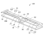
図1に示すように、本発明の実施形態に係る多周波アンテナモジュール100は、携帯電話機及びタブレットパソコン等の無線通信装置に使用される。多周波アンテナモジュール100は、基板200に設けられ、且つ高周波部10、第一低周波部21、第二低周波部31、フィードイン端子13、第一接地端子22及び第二接地端子32を備える。高周波部10は、第一放射片11、第二放射片12及び金属片14を含む。第一低周波部21は、第一放射片11を取り囲むように設けられている。第二低周波部31は、第二放射片12を取り囲むように設けられている。
As shown in FIG. 1, a
基板200は、無線通信装置の電気回路基板の一部である。より詳細には、基板200は、前記電気回路基板のキープアウトゾーンとして機能する。
The
本実施形態において、金属片14は、基板200に対して平行になるように基板200の上方に設けられている。フィードイン端子13は、金属片14と基板200との間に位置し、且つその両端は、金属片14及び基板200にそれぞれ垂直に連接されている。フィードイン端子13は、基板200から電流を取得する。第一放射片11は、細長いシート状を呈しており、金属片14の側辺に連接され、且つ金属片14と同一平面内に位置する。第二放射片12は、金属片14の第一放射片11が連接されている側辺の反対側の側辺に連接され、且つ金属片14と同一平面内に位置する。本実施形態において、第二放射片12の金属片14に近い一端の幅は、第二放射片12の金属片14から遠く離れた一端の幅より狭い。
In the present embodiment, the
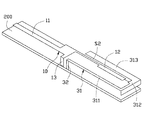
図2に示すように、第一低周波部21は、第一放射帯体211、第二放射帯体212及び第三放射帯体213を含む。第一接地端子22は、基板200の上面における基板200の短手方向に沿って設けられ、且つ該基板200を介して接地される。第一放射帯体211は、基板200の1つの長辺に沿って且つ基板200及び第一接地端子22の一端に対して垂直に連接される。即ち、第一放射帯体211が所在する平面は、基板200の上面及び第一接地端子22が所在する平面に対して垂直である。第二放射帯体212は、互いに垂直に連接されている第一連接片2122及び第二連接片2124を含む。第一連接片2122及び第二連接片2124は、矩形のシート状を呈する。第一連接片2122は、第一放射帯体211の上端から基板200に対して垂直な方向に延伸している。第二連接片2124は、第一連接片2122の上端から基板200の短手方向に対して平行に延在している。第三放射帯体213は、細長いシート状を呈しており、且つ第二連接片2124の第一連接片2122に連接されている一端から離れた一端から第一放射片11に対して平行に延在している。本実施形態において、第三放射帯体213と第一放射片11との間には、第一間隙S1が形成されている。第一間隙S1の幅を調節することで、第一放射片11を流れる電流は、第三放射帯体213にカップリングされて、第三放射帯体213にフィードインされる。
As shown in FIG. 2, the first
図3に示すように、第二低周波部31は、第一延伸片311、第二延伸片312及び第三延伸片313を備える。第二接地端子32は、細長いシート状を呈しており、第一接地端子22の第一放射帯体211から離れた一端に電気的に接続され、且つ基板200に対して垂直である。第一延伸片311は、第二接地端子32の基板200から離れた一端に、該第二接地端子32に対して垂直に連接され、且つ第二放射片12に対して平行に延在している。第二延伸片312は逆「L」字状を呈し、その両端はそれぞれ第一延伸片311及び第三延伸片313に垂直に連接されている。第三延伸片313は、第二放射片12に対して平行に延在している。本実施形態において、第三延伸片313と第二放射片12との間には、第二間隙S2が形成されている。第二間隙S2の幅を調節することで、第二放射片12を流れる電流は第三延伸片313にカップリングされて、第三延伸片313にフィードインされる。
As shown in FIG. 3, the second
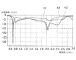
図4に示すように、本発明に係る多周波アンテナモジュール100の反射係数は、曲線43により示され、多周波アンテナモジュール100の第一低周波部21の反射係数は、曲線41により示され、多周波アンテナモジュール100の第二低周波部31の反射係数は、曲線42により示されている。
As shown in FIG. 4, the reflection coefficient of the
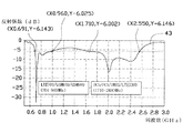
図5から分かるように、本発明の多周波アンテナモジュール100の反射係数における−6dBより小さい共振モードの周波数は、0.691GHz〜0.960GHz及び1.710GHz〜2.550GHzであり、LTE700/GSM(登録商標)850/GSM(登録商標)900(704〜960MHz)、DCS/PCS/UMTS/LTE2300(1710〜2400MHz)の7つの周波数バンドを含む。
As can be seen from FIG. 5, the frequencies of the resonance modes smaller than −6 dB in the reflection coefficient of the
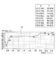
本発明の多周波アンテナモジュール100の放射効率は、図6の曲線61により示されている。本発明の多周波アンテナモジュール100の総放射効率は、図7の曲線71により示されている。図6及び図7から分かるように、多周波アンテナモジュール100は、その動作周波数帯域の範囲内において、好ましい放射効果を備える。
The radiation efficiency of the
以下、本発明の多周波アンテナモジュール100の動作原理について詳細に説明する。電流は、基板200からフィードイン端子13を介して多周波アンテナモジュール100にフィードインされた後、高周波部10の第一放射片11及び第一間隙S1を介して、第一低周波部21の第三放射帯体213と電気容量結合の方式によって、第一低周波部21にフィードインされ、且つ第一接地端子22を介して接地される。これにより、電流回路が形成され、且つ低周波数の第一共振モードが生成される。これと同時に、電流は、高周波部10の第二放射片12及び第二間隙S2を介して、第二低周波部31の第三延伸片313と電気容量結合の方式によって第二低周波部31にフィードインされ、且つ第二接地端子32を介して接地される。これにより、電流回路が形成され、且つ低周波数の第二共振モードが生成される。
Hereinafter, the operation principle of the
高周波の第一共振モードは、高周波部10の第一放射片11、第二放射片12及び金属片14によって生成され、且つ第一低周波部21及び第二低周波部31と共振して電流回路を形成する。高周波の第二共振モードは、主に高周波部10の第一放射片11により生成され、且つ第一低周波部21と共振して電流回路を形成する。
The high-frequency first resonance mode is generated by the
以上の記載から分かるように、本発明の多周波アンテナモジュール100は、高周波部10が第一低周波部21及び第二低周波部31とそれぞれ容量結合して互いにフィードインすることによって、共振長(resonance length)を効果的に短縮し、アンテナモジュールの体積を小さくする。また、本発明の多周波アンテナモジュール100のサイズは、約60mm×13mm×4mmであるため、各種の軽薄で且つスマート化された無線通信装置に適用することができる。
As can be seen from the above description, the
10 高周波部
100 多周波アンテナモジュール
11 第一放射片
12 第二放射片
13 フィードイン端子
14 金属片
200 基板
21 第一低周波部
211 第一放射帯体
212 第二放射帯体
2122 第一連接片
2124 第二連接片
213 第三放射帯体
22 第一接地端子
31 第二低周波部
311 第一延伸片
312 第二延伸片
313 第三延伸片
32 第二接地端子
41 第一低周波部の反射係数の曲線
42 第二低周波部の反射係数の曲線
43 多周波アンテナモジュールの反射係数の曲線
61 多周波アンテナモジュールの放射効率の曲線
71 多周波アンテナモジュールの総放射効率の曲線
S1 第一間隙
S2 第二間隙
DESCRIPTION OF
Claims (9)
前記多周波アンテナモジュールは、高周波部、第一低周波部、第二低周波部、フィードイン端子、第一接地端子及び第二接地端子を備え、前記高周波部は、金属片、第一放射片及び第二放射片を含み、前記第一放射片及び前記第二放射片は、それぞれ前記金属片の互いに反対側に位置する両辺に連接され、前記金属片は、前記フィードイン端子に連接され、前記第一低周波部は、前記第一放射片を取り囲むように設けられ、前記第二低周波部は、前記第二放射片を取り囲むように設けられ、前記第二接地端子は、前記第一接地端子に電気的に接続され、前記第一低周波部及び前記第二低周波部は、前記高周波部の前記第一放射片及び前記第二放射片とそれぞれカップリングすることを特徴とする多周波アンテナモジュール。 A multi-frequency antenna module provided on a substrate,
The multi-frequency antenna module includes a high-frequency part, a first low-frequency part, a second low-frequency part, a feed-in terminal, a first ground terminal, and a second ground terminal, and the high-frequency part includes a metal piece and a first radiation piece And the second radiating piece, the first radiating piece and the second radiating piece are respectively connected to opposite sides of the metal piece, the metal piece is connected to the feed-in terminal, The first low frequency part is provided so as to surround the first radiation piece, the second low frequency part is provided so as to surround the second radiation piece, and the second ground terminal is provided in the first radiation piece. The first low-frequency part and the second low-frequency part are electrically connected to a ground terminal, and are coupled to the first radiating piece and the second radiating piece of the high-frequency part, respectively. Frequency antenna module.
Applications Claiming Priority (2)
| Application Number | Priority Date | Filing Date | Title |
|---|---|---|---|
| CN201310622289.6 | 2013-11-30 | ||
| CN201310622289.6A CN104681928A (en) | 2013-11-30 | 2013-11-30 | Multi-frequency antenna structure |
Publications (1)
| Publication Number | Publication Date |
|---|---|
| JP2015106919A true JP2015106919A (en) | 2015-06-08 |
Family
ID=53266093
Family Applications (1)
| Application Number | Title | Priority Date | Filing Date |
|---|---|---|---|
| JP2014226856A Pending JP2015106919A (en) | 2013-11-30 | 2014-11-07 | Multifrequency antenna module |
Country Status (4)
| Country | Link |
|---|---|
| US (1) | US9570805B2 (en) |
| JP (1) | JP2015106919A (en) |
| CN (1) | CN104681928A (en) |
| TW (1) | TWI628851B (en) |
Families Citing this family (12)
| Publication number | Priority date | Publication date | Assignee | Title |
|---|---|---|---|---|
| CN106299679B (en) * | 2015-06-04 | 2019-06-11 | 启碁科技股份有限公司 | Antenna and radiofrequency signal R-T unit |
| CN105048072B (en) * | 2015-07-31 | 2018-04-17 | 深圳市信维通信股份有限公司 | A kind of antenna assembly for small-sized wireless communication equipment |
| CN107871931B (en) * | 2016-09-26 | 2021-06-15 | 深圳富泰宏精密工业有限公司 | Antenna structure and wireless communication device with same |
| CN107681263A (en) * | 2017-10-20 | 2018-02-09 | 环鸿电子(昆山)有限公司 | Electronic installation and its certainly coupling antenna structure |
| CN109818141B (en) * | 2017-11-22 | 2020-12-08 | 深圳富泰宏精密工业有限公司 | Antenna structure and wireless communication device with same |
| US11515732B2 (en) * | 2018-06-25 | 2022-11-29 | Energous Corporation | Power wave transmission techniques to focus wirelessly delivered power at a receiving device |
| TWI709280B (en) * | 2019-10-01 | 2020-11-01 | 和碩聯合科技股份有限公司 | Antenna structure and communication device |
| TWI713259B (en) * | 2019-12-05 | 2020-12-11 | 和碩聯合科技股份有限公司 | Antenna structure |
| TWI719837B (en) * | 2020-02-18 | 2021-02-21 | 啓碁科技股份有限公司 | Tunable antenna module |
| CN113764865B (en) * | 2020-06-02 | 2024-04-05 | 英业达科技有限公司 | Antenna module |
| TWI743928B (en) * | 2020-08-07 | 2021-10-21 | 緯創資通股份有限公司 | Antenna module |
| WO2024041357A1 (en) * | 2022-08-23 | 2024-02-29 | 华为技术有限公司 | Antenna system and electronic device |
Citations (5)
| Publication number | Priority date | Publication date | Assignee | Title |
|---|---|---|---|---|
| JP2008278219A (en) * | 2007-04-27 | 2008-11-13 | Toshiba Corp | Antenna device |
| WO2012019787A1 (en) * | 2010-08-09 | 2012-02-16 | Sony Ericsson Mobile Communications Ab | Antenna arrangement, dielectric substrate, pcb & device. |
| JP2012165223A (en) * | 2011-02-08 | 2012-08-30 | Lenovo Singapore Pte Ltd | Duan band antenna |
| JP2012178810A (en) * | 2011-02-25 | 2012-09-13 | Acer Inc | Mobile communication device and antenna structure thereof |
| CN103403962A (en) * | 2012-10-17 | 2013-11-20 | 华为终端有限公司 | Multimode broadband antenna module and wireless terminal |
Family Cites Families (5)
| Publication number | Priority date | Publication date | Assignee | Title |
|---|---|---|---|---|
| US6836249B2 (en) * | 2002-10-22 | 2004-12-28 | Motorola, Inc. | Reconfigurable antenna for multiband operation |
| FI20055420A0 (en) * | 2005-07-25 | 2005-07-25 | Lk Products Oy | Adjustable multi-band antenna |
| FI118782B (en) * | 2005-10-14 | 2008-03-14 | Pulse Finland Oy | Adjustable antenna |
| JP4864733B2 (en) * | 2007-01-16 | 2012-02-01 | 株式会社東芝 | Antenna device |
| TWI441388B (en) * | 2010-10-04 | 2014-06-11 | Quanta Comp Inc | Multi - frequency antenna |
-
2013
- 2013-11-30 CN CN201310622289.6A patent/CN104681928A/en active Pending
- 2013-12-20 TW TW102147419A patent/TWI628851B/en active
-
2014
- 2014-11-07 JP JP2014226856A patent/JP2015106919A/en active Pending
- 2014-11-17 US US14/543,266 patent/US9570805B2/en active Active
Patent Citations (5)
| Publication number | Priority date | Publication date | Assignee | Title |
|---|---|---|---|---|
| JP2008278219A (en) * | 2007-04-27 | 2008-11-13 | Toshiba Corp | Antenna device |
| WO2012019787A1 (en) * | 2010-08-09 | 2012-02-16 | Sony Ericsson Mobile Communications Ab | Antenna arrangement, dielectric substrate, pcb & device. |
| JP2012165223A (en) * | 2011-02-08 | 2012-08-30 | Lenovo Singapore Pte Ltd | Duan band antenna |
| JP2012178810A (en) * | 2011-02-25 | 2012-09-13 | Acer Inc | Mobile communication device and antenna structure thereof |
| CN103403962A (en) * | 2012-10-17 | 2013-11-20 | 华为终端有限公司 | Multimode broadband antenna module and wireless terminal |
Also Published As
| Publication number | Publication date |
|---|---|
| US20150155632A1 (en) | 2015-06-04 |
| TWI628851B (en) | 2018-07-01 |
| TW201524001A (en) | 2015-06-16 |
| US9570805B2 (en) | 2017-02-14 |
| CN104681928A (en) | 2015-06-03 |
Similar Documents
| Publication | Publication Date | Title |
|---|---|---|
| JP2015106919A (en) | Multifrequency antenna module | |
| TWI630759B (en) | Antenna structure and wireless communication device using the same | |
| TWI628846B (en) | Antenna structure and wireless communication device having the same | |
| US9774071B2 (en) | Antenna structure | |
| TWI624999B (en) | Atnenna structure and wireless communiation device employing same | |
| TWI622230B (en) | Antenna structure and wireless communication device using the same | |
| TWI662741B (en) | Antenna structure and wireless communication device having the same | |
| TWI628866B (en) | Antenna structure and wireless communication device using the same | |
| TWI619303B (en) | Antenna structure and wileless conmmunication device using the same | |
| TWI619314B (en) | Multiple frequency antenna | |
| CN104752824A (en) | Antenna structure and wireless communication device applying antenna structure | |
| JP2016072951A (en) | Radio communication device | |
| TW201519518A (en) | Antenna assembly and wireless communication device using same | |
| TWI566474B (en) | Multi-band antenna | |
| JP5520753B2 (en) | Bipolar antenna | |
| JP2014239438A (en) | Antenna assembly | |
| US9385417B2 (en) | Broadband antenna and wireless communication device employing same | |
| TW201417399A (en) | Broadband antenna and portable electronic device having same | |
| TW201445811A (en) | Broadband antenna and wireless communication device using same | |
| TWI581499B (en) | Antenna assembly | |
| TW201517380A (en) | Wireless communication device | |
| TWI617087B (en) | Antenna structure and wireless communication device using the same | |
| TWI578613B (en) | Antenna structure | |
| CN104218315B (en) | The wireless communication device of antenna structure and the application antenna structure | |
| CN104103912B (en) | Antenna module |
Legal Events
| Date | Code | Title | Description |
|---|---|---|---|
| A621 | Written request for application examination |
Free format text: JAPANESE INTERMEDIATE CODE: A621 Effective date: 20171106 |
|
| A977 | Report on retrieval |
Free format text: JAPANESE INTERMEDIATE CODE: A971007 Effective date: 20180920 |
|
| A131 | Notification of reasons for refusal |
Free format text: JAPANESE INTERMEDIATE CODE: A131 Effective date: 20181001 |
|
| A02 | Decision of refusal |
Free format text: JAPANESE INTERMEDIATE CODE: A02 Effective date: 20190507 |