EP2704243A2 - Connecting material for a pipe-shaped solid oxide fuel cell, and pipe-shaped solid oxide fuel cell stack including same - Google Patents
Connecting material for a pipe-shaped solid oxide fuel cell, and pipe-shaped solid oxide fuel cell stack including same Download PDFInfo
- Publication number
- EP2704243A2 EP2704243A2 EP12776006.4A EP12776006A EP2704243A2 EP 2704243 A2 EP2704243 A2 EP 2704243A2 EP 12776006 A EP12776006 A EP 12776006A EP 2704243 A2 EP2704243 A2 EP 2704243A2
- Authority
- EP
- European Patent Office
- Prior art keywords
- electrode
- solid oxide
- oxide fuel
- fuel cell
- electrode contact
- Prior art date
- Legal status (The legal status is an assumption and is not a legal conclusion. Google has not performed a legal analysis and makes no representation as to the accuracy of the status listed.)
- Granted
Links
Images


Classifications
-
- H—ELECTRICITY
- H01—ELECTRIC ELEMENTS
- H01M—PROCESSES OR MEANS, e.g. BATTERIES, FOR THE DIRECT CONVERSION OF CHEMICAL ENERGY INTO ELECTRICAL ENERGY
- H01M8/00—Fuel cells; Manufacture thereof
- H01M8/02—Details
- H01M8/0271—Sealing or supporting means around electrodes, matrices or membranes
-
- H—ELECTRICITY
- H01—ELECTRIC ELEMENTS
- H01M—PROCESSES OR MEANS, e.g. BATTERIES, FOR THE DIRECT CONVERSION OF CHEMICAL ENERGY INTO ELECTRICAL ENERGY
- H01M8/00—Fuel cells; Manufacture thereof
- H01M8/02—Details
- H01M8/0202—Collectors; Separators, e.g. bipolar separators; Interconnectors
- H01M8/0258—Collectors; Separators, e.g. bipolar separators; Interconnectors characterised by the configuration of channels, e.g. by the flow field of the reactant or coolant
- H01M8/026—Collectors; Separators, e.g. bipolar separators; Interconnectors characterised by the configuration of channels, e.g. by the flow field of the reactant or coolant characterised by grooves, e.g. their pitch or depth
-
- H—ELECTRICITY
- H01—ELECTRIC ELEMENTS
- H01M—PROCESSES OR MEANS, e.g. BATTERIES, FOR THE DIRECT CONVERSION OF CHEMICAL ENERGY INTO ELECTRICAL ENERGY
- H01M8/00—Fuel cells; Manufacture thereof
- H01M8/02—Details
- H01M8/0297—Arrangements for joining electrodes, reservoir layers, heat exchange units or bipolar separators to each other
-
- H—ELECTRICITY
- H01—ELECTRIC ELEMENTS
- H01M—PROCESSES OR MEANS, e.g. BATTERIES, FOR THE DIRECT CONVERSION OF CHEMICAL ENERGY INTO ELECTRICAL ENERGY
- H01M8/00—Fuel cells; Manufacture thereof
- H01M8/10—Fuel cells with solid electrolytes
- H01M8/12—Fuel cells with solid electrolytes operating at high temperature, e.g. with stabilised ZrO2 electrolyte
-
- H—ELECTRICITY
- H01—ELECTRIC ELEMENTS
- H01M—PROCESSES OR MEANS, e.g. BATTERIES, FOR THE DIRECT CONVERSION OF CHEMICAL ENERGY INTO ELECTRICAL ENERGY
- H01M8/00—Fuel cells; Manufacture thereof
- H01M8/24—Grouping of fuel cells, e.g. stacking of fuel cells
- H01M8/241—Grouping of fuel cells, e.g. stacking of fuel cells with solid or matrix-supported electrolytes
- H01M8/2425—High-temperature cells with solid electrolytes
- H01M8/243—Grouping of unit cells of tubular or cylindrical configuration
-
- H—ELECTRICITY
- H01—ELECTRIC ELEMENTS
- H01M—PROCESSES OR MEANS, e.g. BATTERIES, FOR THE DIRECT CONVERSION OF CHEMICAL ENERGY INTO ELECTRICAL ENERGY
- H01M8/00—Fuel cells; Manufacture thereof
- H01M8/24—Grouping of fuel cells, e.g. stacking of fuel cells
- H01M8/2457—Grouping of fuel cells, e.g. stacking of fuel cells with both reactants being gaseous or vaporised
-
- H—ELECTRICITY
- H01—ELECTRIC ELEMENTS
- H01M—PROCESSES OR MEANS, e.g. BATTERIES, FOR THE DIRECT CONVERSION OF CHEMICAL ENERGY INTO ELECTRICAL ENERGY
- H01M8/00—Fuel cells; Manufacture thereof
- H01M8/24—Grouping of fuel cells, e.g. stacking of fuel cells
- H01M8/2465—Details of groupings of fuel cells
- H01M8/2483—Details of groupings of fuel cells characterised by internal manifolds
-
- H—ELECTRICITY
- H01—ELECTRIC ELEMENTS
- H01M—PROCESSES OR MEANS, e.g. BATTERIES, FOR THE DIRECT CONVERSION OF CHEMICAL ENERGY INTO ELECTRICAL ENERGY
- H01M8/00—Fuel cells; Manufacture thereof
- H01M8/10—Fuel cells with solid electrolytes
- H01M8/12—Fuel cells with solid electrolytes operating at high temperature, e.g. with stabilised ZrO2 electrolyte
- H01M2008/1293—Fuel cells with solid oxide electrolytes
-
- Y—GENERAL TAGGING OF NEW TECHNOLOGICAL DEVELOPMENTS; GENERAL TAGGING OF CROSS-SECTIONAL TECHNOLOGIES SPANNING OVER SEVERAL SECTIONS OF THE IPC; TECHNICAL SUBJECTS COVERED BY FORMER USPC CROSS-REFERENCE ART COLLECTIONS [XRACs] AND DIGESTS
- Y02—TECHNOLOGIES OR APPLICATIONS FOR MITIGATION OR ADAPTATION AGAINST CLIMATE CHANGE
- Y02E—REDUCTION OF GREENHOUSE GAS [GHG] EMISSIONS, RELATED TO ENERGY GENERATION, TRANSMISSION OR DISTRIBUTION
- Y02E60/00—Enabling technologies; Technologies with a potential or indirect contribution to GHG emissions mitigation
- Y02E60/30—Hydrogen technology
- Y02E60/50—Fuel cells
Definitions
- the present invention relates a connector for a tubular solid oxide fuel cell and a tubular solid oxide fuel cell stack including the same. More particularly, the present invention relates to a connector for a tubular solid oxide fuel cell that electrically connects a plurality of tubular solid oxide fuel cells to each other and a tubular solid oxide fuel cell stack including the same.
- solid oxide fuel cells so-called, the third generation fuel cells, were studied later than phosphoric acid fuel cells (PAFCs) and molten carbonate fuel cells (MCFCs), the solid oxide fuel cells are expected to be in practical use in the near future, subsequent to the PAFCs and the MCFCs, by virtue of the recent rapid development of material technologies.
- PAFCs phosphoric acid fuel cells
- MCFCs molten carbonate fuel cells
- Such a solid oxide fuel cell is operated at a high temperature ranging from about 600°C to about 1,000°C., and has advantages in that it is the most highly efficient of existing fuel cells, there are few pollutants discharged, a fuel reformer is not necessary, and a combined power generation is feasible.
- the solid oxide fuel cell may be largely classified into a tubular solid oxide fuel cell and a planar solid oxide fuel cell.
- a planar solid oxide fuel cell stack has a power density greater than that of a tubular solid oxide fuel cell stack.
- the tubular solid oxide fuel cell may be classified into an air electrode-supported type and a fuel electrode-supported type.
- the air electrode-supported type suffers from a disadvantage of a relatively high manufacturing cost because air electrode materials, such as lanthanum(La), manganese(Mn), etc., are very expensive, and LaSrMnO 3 (LSM) that is a raw material for the air electrode is difficult in manufacturing.
- the unit cell has a low mechanical strength and does not withstand impact because the air electrode serving as the support is made of ceramic.
- the tubular fuel electrode support used in the fuel electrode-supported solid oxide fuel cell satisfies demands required as both the electrode and the support, and is advantageous in that co-sintering is feasible because reactivity between the support and an electrolyte layer is low, and a stable fuel cell stack is fabricated due to a high mechanical strength of the support.
- a stack of the tubular solid oxide fuel cell has to be provided. Also, to manufacture the stack of the tubular solid oxide fuel cell, it is necessary to develop a connector for electrically connecting unit cells to each other.
- An object of the present invention provides a connector for a tubular solid oxide fuel cell, which electrically connects tubular solid oxide fuel cells to each other.
- Another object of the present invention provides a stack of a tubular solid oxide fuel cell including the connector.
- a connector for a solid oxide fuel cell including a conductive body part for electrically connecting solid oxide fuel cells to each other, each including a first electrode having an inner passage and an electrolyte and second electrode successively stacked on the first electrode to expose both ends of the first electrode,.
- the conductive body part includes a first electrode contact groove and a second electrode contact groove.
- the first electrode contact groove accommodates at least one portions of the exposed portion of the first electrode and a second electrode of the first solid oxide fuel cell in a top surface thereof and is electrically connected to the first electrode of the first solid oxide fuel cell.
- the second electrode contact groove accommodates at least one portions of the exposed portion of the first electrode and the second electrode in a bottom surface thereof and is electrically connected to the second electrode of the second solid oxide fuel cell.
- the first electrode contact grooves may include an electrode contact part and an electrode accommodation part.
- the electrode contact part may have a semicircular cross-section with a first diameter to accommodate the exposed first electrode of the first solid oxide fuel cell.
- the electrode accommodation part may have a semicircular cross-section with a second diameter greater than the first diameter to accommodate the second electrode of the first solid oxide fuel cell.
- An insulating layer may be disposed on the electrode accommodation part.
- the second electrode contact groove may have the semicircular cross-section with a third diameter equal to the second diameter or less than the second diameter.
- the body part may further include a first through hole and a second through hole.
- the first through hole may penetrate through the body part and be connected to a first end of the first electrode contact groove and a first end of the second electrode contact groove which are adjacent to each other.
- the first through hole may penetrate through the body part and be connected to a second end of the first electrode contact groove and a second end of the second electrode contact groove which are adjacent to each other.
- the body part may further include a third through hole penetrating through the body part in a portion at which at least one portion of the second electrodes of the first and second solid oxide fuel cells is disposed.
- the body part may further include an electrode contact bar connecting both facing ends of the third through hole to each other and electrically connected to the second electrode of the second tubular solid oxide fuel cell.
- a solid oxide fuel cell stack includes first and second solid oxide fuel cells and an intermediate connector.
- Each of the first and second solid oxide fuel cells includes a first electrode having an inner passage and an electrolyte and second electrode successively stacked on the first electrode to expose both ends of the first electrode.
- the intermediate connector includes a first body part having a first electrode contact groove for accommodating the first solid oxide fuel cell in a top surface thereof and a second electrode contact groove for accommodating the second solid oxide fuel cell in a bottom surface thereof.
- the first electrode contact groove accommodates at least one portions of the exposed portion of the first electrode and a second electrode of the first solid oxide fuel cell and is electrically connected to the exposed portion of the first electrode of the first solid oxide fuel cell.
- the second electrode contact groove accommodates at least one portions of the exposed portion of the first electrode and the second electrode of the second solid oxide fuel cell and is electrically connected to the second electrode of the second solid oxide fuel cell.
- the solid oxide fuel cell stack may further include an upper connector and a lower connector.
- the upper connector may include a second body part having a third electrode contact groove accommodating the first solid oxide fuel cell together with the first electrode contact groove and electrically connected to the second electrode of the first solid oxide fuel cell.
- the lower connector may include a third body part having a fourth electrode contact groove accommodating the second solid oxide fuel cell together with the second electrode contact groove and electrically connected to the first electrode of the second solid oxide fuel cell.
- the first body part may include a first through hole connected to an inner passage of each of the first and second solid oxide fuel cells
- the second body part may include a first gas groove connected to the first through hole
- the third body part may include a second gas groove connected to the first through hole and a first gas injection hole for injecting a first gas into the second gas groove.
- the first body part may include a second through hole formed in a position at which the second electrode of each of the first and second solid oxide fuel cells is disposed
- the second body part may include a third gas groove connected to the second through hole
- the third body part may include a fourth gas groove connected to the second through hole and a second gas injection hole for injecting a second gas into the fourth gas groove.
- the solid oxide fuel cell stack may further include: a first insulating member disposed between the intermediate connector and the upper connector to insulate the intermediate from the upper connector; and a second insulating member disposed between the intermediate connector and the lower connector to insulate the intermediate from the lower connector.
- the tubular solid oxide fuel cell may be accommodated in the electrode contact groove formed in the connector to form the stable solid oxide fuel cell stack. Also, since the passages through which hydrogen H2 and air flow are formed in the connector, the solid oxide fuel cell stack that is easily sealed may be manufactured. Also, when the solid oxide fuel cell stack is manufactured by using the connectors according to the embodiments of the present invention, an additional constitution for collecting electricity may be unnecessary, and the stack assembling process may be simplified.
- first and second are used herein to describe various elements, these elements should not be limited by these terms. Terms are only used to distinguish one component from other components. For example, a component referred to as a first component in one embodiment can be referred to as a second component in another embodiment.
- FIG. 1 is a perspective view of a solid oxide fuel cell stack according to a first embodiment of the present invention
- FIG. 2 is a cross-sectional view of a tubular solid oxide fuel cell of FIG. 1
- FIGS. 3 and 4 are perspective views of an intermediate connector of FIG. 1
- FIG. 5 is a perspective view of an upper connector of FIG. 1
- FIG. 6 is a perspective view of a lower connector of FIG. 1 .
- a solid oxide fuel cell stack 1000 includes an upper connector 20, a lower connector 30, at least one intermediate connector 100 disposed between the upper connector 20 and the lower connector 30, at least one first tubular solid oxide fuel cell 10a disposed between the upper connector 20 and the intermediate connector 100, and at least one second tubular solid oxide fuel cell 10b disposed between the lower connector 30 and the intermediate connector 100.
- the tubular solid oxide fuel cell 10 may include various types of solid oxide fuel cells, each of which has a closed loop cross-section.
- the "tubular solid oxide fuel cell” may include a tubular solid oxide fuel cell having a circular cross-section, a solid oxide fuel cell having an oval cross-section, a flat-tubular solid oxide fuel cell, and polygonal solid oxide fuel cell having a rectangular cross-section.
- the tubular solid oxide fuel cell 10 applied to the first embodiment of the present invention may include a tubular first electrode 11 having a passage therein, an electrolyte 13 stacked on the first electrode 11, and a second electrode 15 stacked on the electrolyte 13.
- the electrolyte 13 may be formed of an oxygen ion-conductive material.
- the electrolyte 13 may be formed of a ceramic material such as yttria-stabilized zirconia (YSZ), (La,Sr)(Ga, Mg)O 3 , Ba(Zr,Y)O 3 , Gd-doped CeO 2 (GDC), or Y 2 O 3 doped CeO 2 (YDC) which has high ion conductivity, superior stability in oxidation reduction atmosphere, and superior mechanical properties.
- YSZ yttria-stabilized zirconia
- La,Sr)(Ga, Mg)O 3 Ba(Zr,Y)O 3
- GDC Gd-doped CeO 2
- YDC Y 2 O 3 doped CeO 2
- the tubular first electrode 11 having the passage therein may be a fuel electrode
- the second electrode 15 stacked on the electrolyte may be an air electrode
- the tubular solid oxide fuel cell 10 may be a fuel electrode-supported solid oxide fuel cell.
- a fuel gas may be supplied into the fuel electrode through the inner passage
- air containing oxygen may be supplied through a surface of the air electrode that is an outer layer.
- Hydrogen (H 2 ) may be uses as the fuel gas supplied into the inner passage of the fuel electrode.
- the hydrogen (H 2 ) supplied through the inner passage of the fuel electrode may flow up to a portion adjacent to the electrolyte 13 through the inside of the fuel electrode.
- the air supplied into the air electrode may generate oxygen ions through the reduction reaction of the oxygen.
- the oxygen ions generated in the air electrode may move toward the fuel electrode through the electrolyte 13.
- the oxygen ions moved into the fuel electrode and the hydrogen supplied into the fuel electrode may react with each other to generate electrical energy.
- the fuel electrode may have a porous structure by using a mixture of YSZ and nickel so that the hydrogen (H 2 ) flows through the inside of the fuel electrode as described above.
- the air electrode may have a porous structure by using Lanthanum strontium manganite (LSM), Lanthanum strontium cobalt ferrite (LSCF), or the like so that the oxygen flows through the air electrode as described above.
- LSM Lanthanum strontium manganite
- LSCF Lanthanum strontium cobalt ferrite
- the LSM may be a compound of lanthanum (La), strontium (Sr), and manganese (Mn), and the LSCF may be a compound of lanthanum (La), strontium (Sr), cobalt (Co), and iron (Fe).
- the tubular first electrode 11 having the inner passage may be an air electrode
- the second electrode 15 stacked on the electrolyte 13 may be a fuel electrode
- the tubular solid oxide fuel cell 10 may be an air electrode-supported solid oxide fuel cell.
- the present invention may be equally or similarly applied to an embodiment in which the tubular first electrode 11 having the inner passage is provided as the air electrode, and the second electrode 15 stacked on the electrolyte 13 is provided as the fuel electrode.
- the electrolyte 13 may be disposed on the first electrode so that both edges of the first electrode 11 are exposed by a predetermined width thereof.
- the second electrode 15 may be disposed on the electrolyte 13 so that both edges of the electrolyte 13 are exposed by a predetermined width thereof.
- the tubular solid oxide fuel cell 10 may further include a sealing part 17 surrounding the exposed portions of the electrolyte 13.
- the sealing part 17 may be formed of a flexible glass sealing material.
- a glass sealing material may be formed in a sheet shape and then be rolled on the tubular solid oxide fuel cell 10 to form the sealing part 17.
- the sealing part 17 may prevent hydrogen and/or oxygen from flowing through spaces between first and second contact grooves 110 and 120 (that will be described later) and the tubular solid oxide fuel cell 10 that is accommodated into the first and second contact grooves 110 and 120. Detailed descriptions with respect to the function of the sealing part 17 will be described below.
- the exposed portions of the first electrode 11 may be coated with silver paste. Also, to improve electrical connection performance between the second electrode 15 and the connector of the tubular solid oxide fuel cell 10, the exposed portions of the second electrode 15 may be surrounded by a conductive wire or mesh.
- the electrical connect between a specific portion and the second electrode 15 of the tubular solid oxide material may include a case of direct contact between “the specific portion” and “the second electrode 15 of the tubular solid oxide fuel cell 10" as well as a case of contact between "the specific portion” and “the conductive wire or mesh that is wound around the second electrode 15 of the tubular solid oxide fuel cell 10".
- the tubular solid oxide fuel cell 10 applied to the present invention may further include various functional layers (not shown) between the first electrode 11 and the electrolyte 13, between the second electrode 15 and the electrolyte 13, and on the second electrode 15 or in the first electrode 11.
- the functional layers may be provided to improve cell efficiency as necessary.
- the intermediate connector 100 electrically connects the first electrode 11 of the first tubular solid oxide fuel cell 10a disposed between the upper connector 20 and the intermediate connector 100 to the second electrode 15 of the second tubular solid oxide fuel cell 10b disposed between the lower connector 30 and the intermediate connector 100.
- the intermediate connector 100 electrically connect the first electrodes 11 of the plurality of first tubular solid oxide fuel cells 10a to each other as well as electrically connects the plurality of second electrodes 15 of the second tubular solid oxide fuel cells 10b to each other.
- the plurality of first tubular solid oxide fuel cells 10a that are connected to each other in parallel and the plurality of second tubular solid oxide fuel cells 10b that are connected to each other in parallel are connected to each other in series.
- a plurality of intermediate connectors 100 may be disposed between the upper connector 20 and the lower connector 30. Also, the number of intermediate connector 100 may be adequately adjusted as necessary.
- the intermediate connector 100 includes a first body part 100a.
- the first body part 100a may be formed on only a conductive material.
- a conductive material may be applied to a surface of an insulating base to form the first body part 100a.
- the first body part 100a may have top and bottom surfaces facing each other and side surfaces.
- the first body part 100a may have a rectangular shape.
- the first body part 100a includes at least one first electrode contact groove 110, at least one second electrode contact groove 120, two first through holes 130, and a second through hole 140.
- the at least one first electrode contact grove 110 is formed in a top surface of the first body part 100a facing the upper connector 20.
- the first electrode contact grooves 110 may extend in a first direction in parallel to each other. In this case, the first electrode contact grooves 110 are arranged in a second direction perpendicular to the first direction.
- the first electrode contact grooves 110 may also have the same size and structure.
- each of the first electrode contact grooves 110 may be changed in size and structure according to the size and structure of each of the first tubular solid oxide fuel cells 10a accommodated in the first electrode contact grooves 110.
- the first electrode contact groove 110 may have a semicircular cross-section.
- Each of the first electrode contact grooves 110 may include a first end connected to a left first through hole 130a of two first through holes 130 that are spaced apart from each other and a second end connected to the right first through hole 130b.
- each of the first electrode contact grooves 110 may include a left-side electrode contact part 111a having a predetermined width from the first end, a right-side electrode contact part 111b having a predetermined width from the second end, and an electrode accommodation part 113 disposed between the left-side electrode contact part 111a and the right-side electrode contact part 111b.
- a left end of the first tubular solid oxide fuel cell 10a i.e., a portion of the left first electrode 11 of the exposed first electrodes 11 of the first tubular solid oxide fuel cell 10a may be accommodated into the left electrode contact part 111a of the first electrode contact groove 110.
- the accommodated portion of the first electrode 11 is electrically connected to the left electrode contact part 111a of the first electrode contact groove 110.
- a right end of the first tubular solid oxide fuel cell 10a i.e., a portion of the right first electrode 11 of the exposed first electrodes 11 of the first tubular solid oxide fuel cell 10a may be accommodated into the right electrode contact part 111b of the first electrode contact groove 110.
- a conductive oxidation protection layer (not shown) may be disposed on the electrode contact part 111 of the first electrode contact groove 110 to prevent the electrode contact part 111 of the first electrode contact groove 110 form being oxidized and to improve electrical connection performance between the electrode contact part 111 of the first electrode contact groove 110 and the first electrode 11 of the first tubular solid oxide fuel cell 10a.
- the conductive oxidation protection layer may be a metal-based thin film or conductive ceramic thin film which is not well oxidized.
- the metal-based thin film may be formed by depositing, plating, or coating a precious metal such as Ag or Pt, Ni, Ni-Co alloy, a Mn-Co alloy or by applying paste containing the metal component.
- a precious metal such as Ag or Pt, Ni, Ni-Co alloy, a Mn-Co alloy or by applying paste containing the metal component.
- the conductive ceramic thin film may be formed by coating LSM or spinel-based (Mn,Cr)304 or (Mn,Co)304 or by applying paste containing the ceramic component.
- At least one portions of the portion of the first tubular solid oxide fuel cell 10a on which the sealing part 17 is disposed and the portion of the first tubular solid oxide fuel cell 10a on which the second electrode 15 is disposed are accommodated into the electrode accommodation part 113 of the first electrode contact groove 110.
- the first electrode contact groove 110 may have a semicircular cross-section corresponding to the circular cross-section.
- the portion of the first tubular solid oxide fuel cell 10a on which the sealing part 17 and the second electrode 15 are disposed may have an outer diameter greater than that of the portion of the first tubular solid oxide fuel cell 10a to which the first electrode 11 is exposed.
- the left/right-side electrode contact parts 111a and 111b of the first electrode contact groove 110 in which the exposed portion of the first electrode 11 of the first tubular solid oxide fuel cell 10a is accommodated may have a diameter less than that of each of the portion of the first tubular solid oxide fuel cell 10a on which the sealing part 17 is disposed and the electrode accommodation part 113 accommodating the portion of the first tubular solid oxide fuel cell 10a on which the second electrode 15 is disposed.
- the electrode accommodation part 113 may have a sectional diameter greater than that of the portion of the first tubular solid oxide fuel cell 10a on which the second electrode 15 is disposed.
- the electrode accommodation part 113 may be determined in sectional diameter so that the electrode accommodation part 113 of the first electrode contact groove 110 and the portion of the second electrode 15 of the first tubular solid oxide fuel cell 10a, which is accommodated in the electrode accommodation part 113 are spaced apart from each other.
- the second electrode 15 and the first body part 100a of the first tubular solid oxide fuel cell 10a may be insulated from each other.
- an insulating layer may be disposed on the electrode accommodation part 113 of the first electrode contact groove 110.
- At least one second electrode contact groove 120 is formed in a bottom surface of the first body part 110a facing the lower connector 30.
- three second electrode contact grooves 120 are exemplified as shown in the drawings.
- the second electrode contact grooves 120 extend in the first direction in parallel to each other.
- the second electrode contact grooves 120 are arrange din the second direction perpendicular to the first direction.
- the second electrode contact grooves 120 may be formed directly below positions in which the first electrode contact grooves 110, respectively.
- the second electrode contact grooves 120 may be alternately disposed with respect to the first electrode contact grooves 110.
- the second electrode contact grooves 120 may also have the same size and structure. That is, each of the second electrode contact grooves 120 may be changed in size and structure according to the size and structure of each of the second tubular solid oxide fuel cells 10b accommodated in the second electrode contact grooves 120. For example, when the second tubular solid oxide fuel cell 10b has a circular cross-section, the second electrode contact groove 120 may have a semicircular cross-section.
- Each of the second electrode contact grooves 120 may include a first end connected to the left first through hole 130a of the two first through holes 130 that are spaced apart from each other and a second end connected to the right first through hole 130b. That is, the first ends of the first and second electrode contact grooves 110 and 120 may be connected to the left first through hole 130a, and the second ends may be connected to the right first through hole 130b. Unlike the first electrode contact grooves 110, each of the second electrode contact grooves 120 may have a semicircular shape with a predetermined diameter.
- the portion of the second tubular solid oxide fuel cell 10b on which the sealing part 17 and the second electrode 15 are disposed may have an outer diameter greater than that of the portion of the first tubular solid oxide fuel cell 10a to which the first electrode 11 is exposed.
- the portion on which the second electrode is disposed may be in contact with a bottom surface of the second electrode contact groove 120, but the exposed first electrode 11 may be spaced apart from the bottom surface of the second electrode contact groove 120.
- each of the second electrode contact groove 120 may have a sectional diameter greater than or equal to that of the portion of the second tubular solid oxide fuel cell 10b on which the second electrode 15 is disposed and less than or equal to that of the electrode accommodation part 113 of each of the first electrode contact grooves 110.
- a conductive oxidation protection layer (not shown) may be disposed on the portion of the second electrode contact groove 120, which is in contact with the second electrode 15 of the second tubular solid oxide fuel cell 10b to prevent the portion of the second contact groove 120, which is in contact with the second electrode 15 of the second tubular solid oxide fuel cell 10b from being oxidized and to improve electrical connection performance between the second electrode contact groove 120 and the second electrode 15 of the second tubular solid oxide fuel cell 10b.
- the conductive oxidation protection layer may be a metal-based thin film or conductive ceramic thin film which is not well oxidized.
- the metal-based thin film may be formed by depositing, plating, or coating a noble metal such as Ag or Pt, Ni, Ni-Co alloy, or Mn-Co alloy or by applying paste containing the metal components.
- the conductive ceramic thin film may be formed by coating LSM or spinel-based (Mn,Cr)304 or (Mn,Co)304 or by applying paste containing the ceramic component.
- an insulating layer (not shown) may be disposed on the portion of the second electrode contact groove 120 on which the exposed first electrode 11 of the second tubular solid oxide fuel cell 10b is disposed.
- the left first through hole 130a of the two first through holes 130 may be disposed adjacent to the first ends of the first and second electrode contact grooves 110 and 120 and thus be spatially connected to all of the first ends.
- the right first through holes 130b of the two first through holes 130 may be disposed adjacent to the second ends of the first and second electrode contact grooves 110 and 120 and thus be spatially connected to all of the second ends. That is, when the first tubular solid oxide fuel cells 10a are accommodated in the first electrode contact grooves 110, and the second tubular solid oxide fuel cell 10b is accommodated in the second electrode contact grooves 120, a first gas may flow through the two first through holes 130 and the inner passages of the first and second tubular solid oxide fuel cells 10a and 10b.
- the two first through holes 130 are connected to each other through only the inner passages of the first and second tubular solid oxide fuel cells 10a and 10b in the tubular solid oxide fuel cell stack 1000.
- the first gas may be hydrogen (H 2 ) that is a fuel for the solid oxide fuel cell.
- the first gas may be air containing oxygen.
- the second through hole 140 may be disposed in the portion of each of the first and second tubular solid oxide fuel cells 100a and 10b on which the second electrode 15 is disposed to pass through the first body part 100a.
- the second through hole 140 may provide a passage for supplying a second gas in the second electrode 15 of the first and second tubular solid oxide fuel cells 10a and 10b.
- the second gas may be air containing oxygen.
- the second gas may be hydrogen (H2) that is a fuel for the tubular solid oxide fuel cell 10.
- H2 hydrogen
- the second through hole 140 in a direction in which each of the first and second electrode contact grooves 110 and 120 extends may be adequately adjusted in width in consideration of supplying efficiency of the second gas with respect to the second electrode 15 and an electrical contact area between the second electrode 15 of the second tubular solid oxide fuel cell 10b and the second electrode contact groove 120.
- each of the first and second contact grooves 110 and 120 may be divided into two parts that are spaced apart from each other by the second through hole 140.
- the first body part 100a may further include at least two first coupling holes 150.
- the first coupling holes 150 may pass through the first body part 100a.
- four first coupling holes 150 may be formed in four edges of the first body part 100a, respectively.
- the first coupling holes 150 may be formed between a left edge of the first body part 100a and the left first through hole 130a and between a right edge of the first body part 100a and the right first through hole 130b.
- a coupling bar (not shown) that will be described later may be inserted into each of the first coupling holes 150.
- the connectors accommodating the solid oxide fuel cell may be easily aligned.
- the stack may be easily assembled.
- the coupling bar may be fixed by using a bolt to form the stable solid oxide fuel cell.
- the upper connector 20 is electrically connected to the second electrodes 15 of the first tubular solid oxide fuel cells 10a to function as an electrode terminal for connecting the second electrodes 15 of the first tubular solid oxide fuel cells 10a to an external device.
- the upper connector may include a conductive second body part 20'.
- the second body part 20' may be formed of only a conductive material.
- a conductive material may be applied to the surface of the insulating base to form the second body part 20'.
- the second body part 20' may have a rectangular shape constituted by a bottom surface facing the intermediate connector 100, a top surface facing the bottom surface, and side surfaces connecting the top and bottom surfaces to each other.
- the second body part 20' may include at least one third electrode contact groove 21 and two first gas grooves 22, and a second gas groove 23.
- the second body part 20' may further include at least one of a first gas injection hole 24 and a second gas injection hole 25.
- the second body part 20' may further include a second coupling hole 26.
- the third electrode contact grooves 21 are formed in the bottom surface of the second body part 20' facing the intermediate material 100. Also, the third electrode contact grooves 21 together with the first electrode contact grooves 110 of the intermediate connector 100 may accommodate the first tubular solid oxide fuel cells 10a.
- the third electrode contact grooves 21 may face the first electrode contact grooves 110 formed in the intermediate connector 100, respectively. That is, the third electrode contact grooves 21 may extend in the first direction in parallel to each other. In this case, the third electrode contact grooves 21 are arrange din the second direction perpendicular to the first direction.
- the third electrode contact grooves 21 may also have the same size and structure.
- Each of the third electrode contact grooves 21 may have a semicircular cross-section.
- Each of the third electrode contact grooves 21 may include a first end connected to a first gas groove 22a formed in a left side of two first gas grooves 22 and a second end connected to the first gas groove 22b formed in a right side.
- Each of the third electrode contact grooves 21 may be a semicircular groove with a predetermined diameter.
- each of the third electrode contact grooves 21 may be a semicircular groove with the same diameter as the second electrode contact groove formed in the intermediate connector 100.
- the portion of the first tubular solid oxide fuel cell 10a on which the sealing part 17 and the second electrode 15 are disposed may have an outer diameter greater than that of the portion of the first tubular solid oxide fuel cell 10a to which the first electrode 11 is exposed.
- the portion on which the third electrode is disposed may be in contact with a bottom surface of the third electrode contact groove 21, and the exposed first electrode 11 may be spaced apart from the bottom surface of the third electrode contact groove 21.
- a conductive oxidation protection layer (not shown) may be disposed on the portion of the third electrode contact hole 21, which is in contact with the second electrode 15 of the first tubular solid oxide fuel cell 10a to prevent the portion of the third contact groove 21, which is in contact with the second electrode 15 of the first tubular solid oxide fuel cell 10a from being oxidized and to improve electrical connection performance between the third electrode contact groove 21 and the second electrode 15 of the first tubular solid oxide fuel cell 10a.
- the conductive oxidation protection layer may be a metal-based thin film or conductive ceramic thin film which is not well oxidized.
- the metal-based thin film may be formed by depositing, plating, or coating a noble metal such as Ag or Pt, Ni, Ni-Co alloy, or Mn-Co alloy or by applying paste containing the metal components.
- the conductive ceramic thin film may be formed by coating LSM or spinel-based (Mn,Cr)304 or (Mn,Co)304 or by applying paste containing the ceramic component.
- an insulating layer (not shown) may be disposed on the portion of the third electrode contact groove 21 on which the exposed first electrode 11 of the first tubular solid oxide fuel cell 10a is disposed.
- the two first gas grooves 22 of the second body part 20' are formed to respectively correspond to the two first through holes 130 formed in the intermediate connector 100 to provide passages through which the first gas flows together with the first through holes 130.
- the left first gas groove 22a of the two first gas grooves 22 of the second body part 20' may be disposed adjacent to the first ends of the third electrode contact grooves 21 and then be connected to the first ends.
- the right first gas groove 22b may be disposed adjacent to the second ends of the third electrode contact grooves 21 and then be connected to the second ends.
- the two first gas grooves 22 of the second body part 20' and the two first through holes 130 formed in the intermediate connector 100 may have the same plane area. However, unlike the first through holes 130 of the intermediate connector 100, the two first gas grooves 22 of the second body part 20' may not pass through the second body part 20'.
- the second gas groove 23 of the second body part 20' is disposed to correspond to the second through hole 140 formed in the intermediate connector 100 to provide a passage through which the second gas flows together with the second through hole 140. That is, the second gas groove 23 of the second body part 20' may be disposed in the portion of the second body part 20' on which the second electrode 15 of the first tubular solid oxide fuel cell 10a is disposed.
- the second gas groove 23 of the second body part 20' may have the same plane area as the second through hole 140 formed in the intermediate connector 100. However, unlike the second through holes 140 of the intermediate connector 100, the second gas grooves 23 of the second body part 20' may not pass through the second body part 20'.
- the second gas groove 23 in a direction in which each of the third electrode contact grooves 21 extends may be adequately adjusted in width in consideration of supplying efficiency of the second gas and an electrical contact area between the second electrode 15 of the first tubular solid oxide fuel cell 10a and the third electrode contact grooves 21.
- each of the third electrode contact grooves 21 may be divided into two parts that are spaced apart from each other by the second gas groove 23.
- bar-shaped first contact protrusions 27 extending in the first direction to respectively electrically contact the second electrodes 15 of the first tubular solid oxide fuel cell 10a may be disposed on the bottom surface of the second gas groove 23.
- bar-shaped second contact protrusions (not shown) extending in the second direction to electrically contact all of the second electrodes 15 of the first tubular solid oxide fuel cell 10a may be disposed on the bottom surface of the second gas groove 23.
- the first gas injection hole 24 may be formed in a side surface of the side surfaces of the second body part 20' facing the ends of the third electrode contact grooves 21.
- the first gas injection hole 24 is connected to the first gas groove 22 to provide a passage for injecting the first gas supplied into the inner passage of the tubular solid oxide fuel cell 10.
- the second gas injection hole 25 may be formed in a side surface of the side surfaces of the second body part 20' disposed adjacent to the second gas groove 23.
- the second gas injection hole 25 is connected to the second gas groove 23 to provide a passage for injecting the second gas supplied into the second electrode 15 of the tubular solid oxide fuel cell 10.
- All of the first and second gas injection holes 24 and 25 may be formed in the second body part 20'.
- only one of the first and second gas injection holes 24 and 25 may be formed in the second body part 20', and the other one may be formed in the lower connector 30 that will be described later in detail.
- the second body part 20' may include second coupling holes 26 respectively connected to the first coupling holes 150 formed in the first body part 100a.
- the second coupling holes 26 may pass through the second body part 20' at positions corresponding to the first coupling holes 150, respectively.
- a coupling bar that will be described later may be inserted into each of the first and second coupling holes 150 and 26.
- the lower connector 30 is electrically connected to the first electrodes 11 of the second tubular solid oxide fuel cells 10b to function as electrode terminals for connecting the first electrodes 11 of the second tubular solid oxide fuel cells 10b to an external device.
- the lower connector may include a conductive third body part 30'.
- the third body part 30' may be formed of only a conductive material.
- a conductive material may be applied to the surface of the insulating base to form the third body part 30'.
- the third body part 30' may have a rectangular shape constituted by a top surface facing the intermediate connector 100, a bottom surface facing the bottom surface, and side surfaces connecting the top and bottom surfaces to each other.
- the third body part 30' may include at least one fourth electrode contact groove 31, two third gas grooves, and a fourth gas groove 33. Also, the third body part 30' may further include a third coupling hole 36. Also, when the first and second gas injection holes 24 and 25 are not formed in the second body part 20', the third body part 30' may further include third and fourth gas injection holes 34 and 35.
- the fourth electrode contact grooves 31 are formed in the top surface of the third body part 30' facing the intermediate material 100. Also, the fourth electrode contact grooves 31 together with the second electrode contact grooves 120 of the intermediate connectors 100 may accommodate the second tubular solid oxide fuel cells 10b.
- the fourth electrode contact grooves 31 may face the second electrode contact grooves 120 formed in the intermediate connector 100, respectively. That is, the fourth electrode contact grooves 31 may extend in the first direction in parallel to each other. In this case, the fourth electrode contact grooves 31 are arrange din the second direction perpendicular to the first direction.
- the fourth electrode contact grooves 31 may also have the same size and structure.
- Each of the fourth electrode contact grooves 31 may have a semicircular cross-section.
- Each of the fourth electrode contact grooves 31 may include a first end connected to a third gas groove 32a formed in a left side of two third gas grooves 32 and a second end connected to the third gas groove 32b formed in a right side.
- each of the fourth electrode contact grooves 31 may include a left-side electrode contact part 31a having a predetermined width from the first end, a right-side electrode contact part 31c having a predetermined width from the second end, and an electrode accommodation part 31b disposed between the left-side electrode contact part 31a and the right-side electrode contact part 31c.
- a left end of the first tubular solid oxide fuel cell 10a i.e., a portion of the left first electrode 11 of the exposed first electrodes 11 of the second tubular solid oxide fuel cell 10b may be accommodated into the left electrode contact part 31a of the fourth electrode contact grooves 31.
- the accommodated portion of the first electrode 11 is electrically connected to the left electrode contact part 31a of the fourth electrode contact groove 31.
- a right end of the second tubular solid oxide fuel cell 10b i.e., a portion of the right first electrode 11 of the exposed first electrodes 11 of the second tubular solid oxide fuel cell 10b may be accommodated into the right electrode contact part 31c of the fourth electrode contact groove 31.
- a conductive oxidation protection layer (not shown) may be disposed on the electrode contact parts 31a and 31c of the fourth electrode contact groove 31 to prevent the electrode contact part 111 of the fourth electrode contact groove 31 form being oxidized and to improve electrical connection performance between the electrode contact parts 31a and 31c of the fourth electrode contact groove 31 and the first electrode 11 of the second tubular solid oxide fuel cell 10b.
- the conductive oxidation protection layer may be a metal-based thin film or conductive ceramic thin film which is not well oxidized.
- the metal-based thin film may be formed by depositing, plating, or coating a noble metal such as Ag or Pt, Ni, Ni-Co alloy, or Mn-Co alloy or by applying paste containing the metal components.
- the conductive ceramic thin film may be formed by coating LSM or spinel-based (Mn,Cr)304 or (Mn,Co)304 or by applying paste containing the ceramic component. At least one portions of the portion of the second tubular solid oxide fuel cell 10b on which the sealing part 17 is disposed and the portion of the second tubular solid oxide fuel cell 10b on which the second electrode 15 is disposed are accommodated into the electrode accommodation part 31 of the fourth electrode contact groove 31.
- the fourth electrode contact groove 31 may have a semicircular cross-section corresponding to the circular cross-section. Since the electrolyte 13 is stacked on the first electrode 11, and the sealing part 17 and the second electrode 15 are stacked on the electrolyte 13, the portion of the second tubular solid oxide fuel cell 10b on which the sealing part 17 and the second electrode 15 are disposed may have an outer diameter greater than that of the portion of the second tubular solid oxide fuel cell 10b to which the second electrode 11 is exposed.
- the left/right-side electrode contact parts 31a and 31c of the fourth electrode contact groove 31 in which the exposed portion of the first electrode 11 of the second tubular solid oxide fuel cell 10b is accommodated may have a diameter less than that of each of the portion of the second tubular solid oxide fuel cell 10b on which the sealing part 17 is disposed and the electrode accommodation part 31b accommodating the portion of the second tubular solid oxide fuel cell 10b on which the second electrode 15 is disposed.
- the electrode accommodation part 31b may have a sectional diameter greater than that of the portion of the second tubular solid oxide fuel cell 10b on which the second electrode 15 is disposed.
- the electrode accommodation part 31b may be determined in sectional diameter so that the electrode accommodation part 31b of the fourth electrode contact groove 31 and the portion of the second electrode 15 of the second tubular solid oxide fuel cell 10b, which is accommodated in the electrode accommodation part 31b are spaced apart from each other.
- the second electrode 15 and the third body part 30' of the second tubular solid oxide fuel cell 10b may be insulated from each other. Also, to insulate the second electrode 15 of the second tubular solid oxide fuel cell 10b and the third body part 30' from each other, an insulating layer (not shown) may be disposed on the electrode accommodate part of the fourth electrode contact groove 31.
- the two third gas grooves 32 are formed to respectively correspond to the two first through holes 130 formed in the intermediate connector 100 to provide passages through which the first gas flows together with the first through holes 130 of the intermediate material 100 and the first gas groove 22 of the upper connector 20. That is, the left third gas groove 32a of the two third gas grooves 32 of the third body part 30' may be disposed adjacent to the first ends of the fourth electrode contact grooves 31 and then be connected to the first ends. Also, the right first gas groove 32b may be disposed adjacent to the second ends of the fourth electrode contact grooves 31 and then be connected to the second ends.
- the two third gas grooves 32 and the two first through holes 130 may have the same plane area. However, unlike the first through holes 130 of the intermediate connector 100, the third gas grooves 23 may not pass through the third body part 30'.
- the fourth gas groove 33 is formed to correspond to the second through hole 140 to provide a passage through which the second gas flows together with the second through hole 140 and the second gas groove 23. That is, the fourth gas groove 33 may be disposed in the portion of the third body part 30' on which the second electrode 15 of the second tubular solid oxide fuel cell 10b is disposed.
- the fourth through holes 33 may have the same plane area as the second through hole 140. However, unlike the second through holes 140 of the intermediate connector 100, the fourth gas grooves 33 may not pass through the third body part 30'.
- each of the fourth electrode contact grooves 31 may be divided into two parts that are spaced apart from each other by the fourth gas groove 33.
- the third gas injection hole 34 may be formed in a side surface of the side surfaces of the third body part 30' facing the ends of the fourth electrode contact grooves 31.
- the third gas injection hole 34 is connected to the third gas groove 32 to provide a passage for injecting the first gas supplied into the inner passage of the tubular solid oxide fuel cell 10.
- the fourth gas injection hole 35 may be formed in a side surface of the side surfaces of the third body part 30' disposed adjacent to the fourth gas groove 33.
- the fourth gas injection hole 35 is connected to the fourth gas groove 33 to provide a passage for injecting the second gas supplied into the second electrode 15 of the tubular solid oxide fuel cell 10.
- All of the third and fourth gas injection holes 32 and 35 may be formed in the second body part 30'.
- only one of the third and fourth gas injection holes 32 and 35 may be formed in the fourth body part 30'.
- the fourth gas injection hole 35 may be formed in the third body part 30'.
- the third body part 30' may include third coupling holes 36 respectively connected to the first coupling holes 150 formed in the first body part 100a. That is, the third coupling holes 36 may pass through the third body part 30' at positions corresponding to the first coupling holes 150, respectively.
- the solid oxide fuel cell 1000 may further include an insulating sealing member 160 disposed between the connectors adjacent to each other.
- the first and second electrodes 11 and 15 of the tubular solid oxide fuel cell 10, which are disposed between the adjacent connectors may be short-circuited.
- the connectors have to be insulated from each other.
- the connectors may be sealed therebetween to prevent the first and second gases injected into the tubular solid oxide fuel cell stack 1000 from leaking to the outside.
- the insulating sealing member 160 may electrically insulate the adjacent connectors as well as prevent the first or second gas from leaking to the outside of the solid oxide fuel cell stack 1000 through a gap between the adjacent connectors.
- the insulating sealing member 160 may be coated on an edge of a top surface of the lower connector of the adjacent connectors or an edge of a bottom surface of the upper connector. Alternatively, the insulating sealing member 160 may be a separate member disposed between the edge of the upper connector of the adjacent connectors and the lower connector.
- the insulating sealing member 160 may include a first insulating sealing member (not shown) disposed between the upper connector 20 and the intermediate connector 100, a second insulating sealing member (not shown) disposed between the intermediate connector 100 and the lower connector 30, and a third insulating sealing member (not shown) disposed between intermediate connectors 100 when at least two intermediate connectors 100 are provided.
- the solid oxide fuel cell stack 100 may further include a coupling bar (not shown) inserted into the first to third coupling holes 36.
- the coupling bar may include a ceramic tube (not shown).
- a nut (not shown) is coupled after a bolt (not shown) is inserted into the ceramic tube that is used as the coupling bar, the stacked connectors 20, 100, and 30 and the tubular solid oxide fuel cells 10 disposed among the connectors 20, 100, and 30 may be stably fixed to improve electrical contact reliability between the electrode contact grooves and the electrodes 11 and 15 of the tubular solid oxide fuel cell 10.
- FIGS. 7 and 8 are perspective views of an intermediate connector that is applied to a solid oxide fuel cell stack according to a second embodiment of the present invention.
- a solid oxide fuel cell stack 1000 includes an upper connector 20, a lower connector 30, an intermediate connector 200, at least one first tubular solid oxide fuel cell 10a disposed between the upper connector 20 and the intermediate connector 200, at least one second tubular solid oxide fuel cell 10b disposed between the lower connector 30 and the intermediate connector 200, an insulating sealing member (not shown), and a coupling bar (not shown).
- the intermediate connector 200 will be mainly described below, and thus, descriptions with respect to other constitutions will be omitted.
- the intermediate connector 200 includes a conductive body part 200'.
- the conductive body part 200' includes first electrode contact grooves 210, second electrode contact grooves 220, first through holes 230, second through holes 240, first electrode contact bars 260, second electrode contact bars 270, and first coupling holes 250. Since the other parts except for the first and second electrode contact bars 260 and 270 have substantially equal or similar to those described in the first embodiment, their detailed description will be omitted.
- the first electrode contact bars 260 are disposed to cross the second through holes 250 in a first direction to which each of the first and second electrode contact grooves 210 and 220 extends.
- the first electrode contact bars 260 electrically contact the second electrodes 17 of the tubular solid oxide fuel cells 10 accommodated in the second electrode contact grooves 220, respectively.
- the first electrode contact bars 260 adjacent to each other may be spaced a predetermined distance from each other.
- the second electrode contact bars 270 are disposed to cross the second through holes 240 in a second direction perpendicular to the first direction. Each of the second electrode contact bars 270 may cross all of the first electrode contact bars 260. The second electrode contact bars 270 electrically contact all of the second electrodes 17 of the tubular solid oxide fuel cells 10 accommodated in the second electrode contact grooves 220. The second electrode contact bars 270 adjacent to each other may be spaced a predetermined distance from each other.
- first and second electrode contact bars 260 and 270 are provided in the current embodiment, only one of the first and second electrode contact bars 260 and 270 may be provided.
- an electrical contact area between the second electrodes 17 of the tubular solid oxide fuel cell 10 accommodated in the second electrode contact grooves 220 and the body part 200' may increase.
- FIGS. 9 and 10 are perspective views of an intermediate connector that is applied to a solid oxide fuel cell stack according to a third embodiment of the present invention.
- a solid oxide fuel cell stack 1000 includes an upper connector 20, a lower connector 30, an intermediate connector 300, at least one first tubular solid oxide fuel cell 10a disposed between the upper connector 20 and the intermediate connector 300, at least one second tubular solid oxide fuel cell 10b disposed between the lower connector 30 and the intermediate connector 300, an insulating sealing member (not shown), and a coupling bar (not shown).
- the intermediate connector 300 will be mainly described below, and thus, descriptions with respect to other constitutions will be omitted.
- the intermediate connector 300 includes a conductive body part 300'.
- the conductive body part 300' includes first electrode contact grooves 310, second electrode contact grooves 320, first through holes 330, a second gas groove 340, second through slits 360, and first coupling holes 350. Since the other parts except for the second electrode contact grooves 320, the second gas groove 340, and the second through slits 360 have substantially equal or similar to those described in the first embodiment, their detailed description will be omitted.
- a second gas groove 340 that divides the first electrode contact grooves 310 into two parts spaced apart from each other is formed in a top surface of the body part having the first electrode contact grooves 310.
- the second gas groove 340 does not pass through the body part 300'.
- a plurality of through slits 360 extending in a second direction perpendicular to a first direction to which each of the first and second electrode contact grooves 310 and 320 extends are formed in the second gas grooves 340.
- the plurality of through slits 360 provide spaces through which a second gas flows.
- the second electrode contact grooves 320 are formed in a bottom surface of the body part 300', and the second electrode contact grooves 320 meet the second through slits 360.
- Each of the second electrode contact grooves 320 continuously extends from an end of one side to an end of the other side of each of the second electrode contact grooves 320 except for the region in which the second through slits 360 are formed.
- the second electrode contact grooves 320 extends extend in a region remaining except for the region in which the second through slits 360 are formed, an electrical contact area between the second electrodes 17 of the tubular solid oxide fuel cell 10 accommodated in the second electrode contact grooves 320 and the body part 300'.
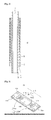
- FIGS. 11 and 12 are perspective views of an intermediate connector that is applied to a solid oxide fuel cell stack according to a fourth embodiment of the present invention.
- a solid oxide fuel cell stack 1000 includes an upper connector 20, a lower connector 30, an intermediate connector 400, at least one first tubular solid oxide fuel cell 10a disposed between the upper connector 20 and the intermediate connector 400, at least one second tubular solid oxide fuel cell 10b disposed between the lower connector 30 and the intermediate connector 400, an insulating sealing member (not shown), and a coupling bar (not shown).
- the intermediate connector 400 will be mainly described below, and thus, descriptions with respect to other constitutions will be omitted.
- the intermediate connector 400 includes a conductive body part 400'.
- the conductive body part 400' includes first electrode contact grooves 410, second electrode contact grooves 420, first through holes 430, second gas grooves 440, and first coupling holes 450. Since the other parts except for the second electrode contact grooves 420 and the second through holes 440 have substantially equal or similar to those described in the first embodiment, their detailed description will be omitted.
- Each of the first electrode contact grooves 410 formed in a top surface of the body part 400' are formed in a region between first and second through holes 430a and 440a which are formed in a left side and a region between first and second through holes 430b and 440b which are formed in a right side and are not formed in the region in which the second through holes 440 are formed and in a region between the second through holes 440.
- each of the first electrode contact grooves 410 are divided into two parts that are spaced apart from each other.
- Each of the second electrode contact grooves 420 formed in a bottom surface of the body part 400' are formed in the region between first and second through holes 430a and 440a which are formed in the left side and the region between first and second through holes 430b and 440b which are formed in the right side as well as in the region between the second through holes 440.
- each of the second electrode contact grooves 420 are divided into three parts that are spaced apart from each other.
- the second electrode contact grooves 420 are formed in the region between the second through holes 440, a contact area between the body part 400' and the second electrode 17 of the tubular solid oxide fuel cell 10 accommodated in the second electrode contact parts 420 may increase.
- FIGS. 13 and 14 are perspective views of an intermediate connector that is applied to a solid oxide fuel cell stack according to a fifth embodiment of the present invention.
- a solid oxide fuel cell stack 1000 includes an upper connector 20, a lower connector 30, an intermediate connector 500, at least one first tubular solid oxide fuel cell 10a disposed between the upper connector 20 and the intermediate connector 500, at least one second tubular solid oxide fuel cell 10b disposed between the lower connector 30 and the intermediate connector 500, an insulating sealing member (not shown), and a coupling bar (not shown).
- the intermediate connector 500 will be mainly described below, and thus, descriptions with respect to other constitutions will be omitted.
- the intermediate connector 500 includes conductive body parts 500' and 500".
- the conductive body parts 500' and 500" include first and second body parts 500' and 500" that are separated from each other.
- the first body part 500' may have substantially the same constitution as the portion of the intermediate connector, which is disposed on a left side of the second through hole according to the first embodiment
- the second body part 500" may have substantially the same constitution as the portion of the intermediate connector, which is disposed on a right side of the second through hole according to the first embodiment.
- the tubular solid oxide fuel cell may be accommodated in the electrode contact groove formed in the connector to manufacture the stable solid oxide fuel cell stack. Also, since the passages through which hydrogen (H 2 ) and air flow are formed in the connector, the solid oxide fuel cell stack that is easily sealed may be manufactured. Also, when the solid oxide fuel cell stack is manufactured by using the connectors according to the embodiments of the present invention, an additional constitution for collecting electricity may be unnecessary, and the stack assembling process may be simplified.
Landscapes
- Life Sciences & Earth Sciences (AREA)
- Engineering & Computer Science (AREA)
- Manufacturing & Machinery (AREA)
- Sustainable Development (AREA)
- Sustainable Energy (AREA)
- Chemical & Material Sciences (AREA)
- Chemical Kinetics & Catalysis (AREA)
- Electrochemistry (AREA)
- General Chemical & Material Sciences (AREA)
- Fuel Cell (AREA)
Abstract
Description
- The present invention relates a connector for a tubular solid oxide fuel cell and a tubular solid oxide fuel cell stack including the same. More particularly, the present invention relates to a connector for a tubular solid oxide fuel cell that electrically connects a plurality of tubular solid oxide fuel cells to each other and a tubular solid oxide fuel cell stack including the same.
- Although solid oxide fuel cells, so-called, the third generation fuel cells, were studied later than phosphoric acid fuel cells (PAFCs) and molten carbonate fuel cells (MCFCs), the solid oxide fuel cells are expected to be in practical use in the near future, subsequent to the PAFCs and the MCFCs, by virtue of the recent rapid development of material technologies. To commercialize the solid oxide fuel cells, advanced nations have devoted tremendous effort to the fundamental research on SOFC and enlarged production scale.
- Such a solid oxide fuel cell is operated at a high temperature ranging from about 600°C to about 1,000°C., and has advantages in that it is the most highly efficient of existing fuel cells, there are few pollutants discharged, a fuel reformer is not necessary, and a combined power generation is feasible.
- The solid oxide fuel cell may be largely classified into a tubular solid oxide fuel cell and a planar solid oxide fuel cell. According to the planar solid oxide fuel cell, a planar solid oxide fuel cell stack has a power density greater than that of a tubular solid oxide fuel cell stack. However, it is difficult to manufacture a large-area fuel cell due to a gas sealing problem, a thermal shock generated by a thermal equilibrium coefficient difference between materials, and the like. In recent years, studies with respect to the tubular solid oxide fuel cell are being actively carried out. The tubular solid oxide fuel cell may be classified into an air electrode-supported type and a fuel electrode-supported type. However, in the case of the air electrode-supported type, the air electrode-supported type suffers from a disadvantage of a relatively high manufacturing cost because air electrode materials, such as lanthanum(La), manganese(Mn), etc., are very expensive, and LaSrMnO3 (LSM) that is a raw material for the air electrode is difficult in manufacturing. In addition, the unit cell has a low mechanical strength and does not withstand impact because the air electrode serving as the support is made of ceramic. To solve the above-described problems, a fuel electrode-supported solid oxide fuel cell using a fuel electrode as the support has been developed.
- The tubular fuel electrode support used in the fuel electrode-supported solid oxide fuel cell satisfies demands required as both the electrode and the support, and is advantageous in that co-sintering is feasible because reactivity between the support and an electrolyte layer is low, and a stable fuel cell stack is fabricated due to a high mechanical strength of the support. To generating high power by using the tubular solid oxide fuel cell, a stack of the tubular solid oxide fuel cell has to be provided. Also, to manufacture the stack of the tubular solid oxide fuel cell, it is necessary to develop a connector for electrically connecting unit cells to each other.
- An object of the present invention provides a connector for a tubular solid oxide fuel cell, which electrically connects tubular solid oxide fuel cells to each other.
- Another object of the present invention provides a stack of a tubular solid oxide fuel cell including the connector.
- According to an aspect of the present invention, a connector for a solid oxide fuel cell, the connector including a conductive body part for electrically connecting solid oxide fuel cells to each other, each including a first electrode having an inner passage and an electrolyte and second electrode successively stacked on the first electrode to expose both ends of the first electrode,. The conductive body part includes a first electrode contact groove and a second electrode contact groove. The first electrode contact groove accommodates at least one portions of the exposed portion of the first electrode and a second electrode of the first solid oxide fuel cell in a top surface thereof and is electrically connected to the first electrode of the first solid oxide fuel cell. The second electrode contact groove accommodates at least one portions of the exposed portion of the first electrode and the second electrode in a bottom surface thereof and is electrically connected to the second electrode of the second solid oxide fuel cell.
- In the embodiments of the present invention, the first electrode contact grooves may include an electrode contact part and an electrode accommodation part. The electrode contact part may have a semicircular cross-section with a first diameter to accommodate the exposed first electrode of the first solid oxide fuel cell. The electrode accommodation part may have a semicircular cross-section with a second diameter greater than the first diameter to accommodate the second electrode of the first solid oxide fuel cell. An insulating layer may be disposed on the electrode accommodation part. The second electrode contact groove may have the semicircular cross-section with a third diameter equal to the second diameter or less than the second diameter.
- In the embodiments of the present invention, the body part may further include a first through hole and a second through hole. The first through hole may penetrate through the body part and be connected to a first end of the first electrode contact groove and a first end of the second electrode contact groove which are adjacent to each other. The first through hole may penetrate through the body part and be connected to a second end of the first electrode contact groove and a second end of the second electrode contact groove which are adjacent to each other. Also, the body part may further include a third through hole penetrating through the body part in a portion at which at least one portion of the second electrodes of the first and second solid oxide fuel cells is disposed.
- In the embodiments of the present invention, the body part may further include an electrode contact bar connecting both facing ends of the third through hole to each other and electrically connected to the second electrode of the second tubular solid oxide fuel cell.
- According to another aspect of the present invention, a solid oxide fuel cell stack includes first and second solid oxide fuel cells and an intermediate connector. Each of the first and second solid oxide fuel cells includes a first electrode having an inner passage and an electrolyte and second electrode successively stacked on the first electrode to expose both ends of the first electrode. The intermediate connector includes a first body part having a first electrode contact groove for accommodating the first solid oxide fuel cell in a top surface thereof and a second electrode contact groove for accommodating the second solid oxide fuel cell in a bottom surface thereof. The first electrode contact groove accommodates at least one portions of the exposed portion of the first electrode and a second electrode of the first solid oxide fuel cell and is electrically connected to the exposed portion of the first electrode of the first solid oxide fuel cell. The second electrode contact groove accommodates at least one portions of the exposed portion of the first electrode and the second electrode of the second solid oxide fuel cell and is electrically connected to the second electrode of the second solid oxide fuel cell.
- In the embodiments of the present invention, the solid oxide fuel cell stack may further include an upper connector and a lower connector. The upper connector may include a second body part having a third electrode contact groove accommodating the first solid oxide fuel cell together with the first electrode contact groove and electrically connected to the second electrode of the first solid oxide fuel cell. The lower connector may include a third body part having a fourth electrode contact groove accommodating the second solid oxide fuel cell together with the second electrode contact groove and electrically connected to the first electrode of the second solid oxide fuel cell.
- In the embodiments of the present invention, the first body part may include a first through hole connected to an inner passage of each of the first and second solid oxide fuel cells, the second body part may include a first gas groove connected to the first through hole, and the third body part may include a second gas groove connected to the first through hole and a first gas injection hole for injecting a first gas into the second gas groove. Also, the first body part may include a second through hole formed in a position at which the second electrode of each of the first and second solid oxide fuel cells is disposed, the second body part may include a third gas groove connected to the second through hole, and the third body part may include a fourth gas groove connected to the second through hole and a second gas injection hole for injecting a second gas into the fourth gas groove.
- In the embodiments of the present invention, the solid oxide fuel cell stack may further include: a first insulating member disposed between the intermediate connector and the upper connector to insulate the intermediate from the upper connector; and a second insulating member disposed between the intermediate connector and the lower connector to insulate the intermediate from the lower connector.
- As described above, according to the embodiments of the present invention, the tubular solid oxide fuel cell may be accommodated in the electrode contact groove formed in the connector to form the stable solid oxide fuel cell stack. Also, since the passages through which hydrogen H2 and air flow are formed in the connector, the solid oxide fuel cell stack that is easily sealed may be manufactured. Also, when the solid oxide fuel cell stack is manufactured by using the connectors according to the embodiments of the present invention, an additional constitution for collecting electricity may be unnecessary, and the stack assembling process may be simplified.
-
-
FIG. 1 is a perspective view of a solid oxide fuel cell stack according to a first embodiment of the present invention. -
FIG. 2 is a cross-sectional view of a tubular solid oxide fuel cell ofFIG. 1 . -
FIGS. 3 and4 are perspective views of an intermediate connector ofFIG. 1 . -
FIG. 5 is a perspective view of an upper connector ofFIG. 1 . -
FIG. 6 is a perspective view of a lower connector ofFIG. 1 . -
FIGS. 7 and 8 are perspective views of an intermediate connector that is applied to a solid oxide fuel cell stack according to a second embodiment of the present invention. -
FIGS. 9 and10 are perspective views of an intermediate connector that is applied to a solid oxide fuel cell stack according to a third embodiment of the present invention. -
FIGS. 11 and 12 are perspective views of an intermediate connector that is applied to a solid oxide fuel cell stack according to a fourth embodiment of the present invention. -
FIGS. 13 and 14 are perspective views of an intermediate connector that is applied to a solid oxide fuel cell stack according to a fifth embodiment of the present invention. - Hereinafter, a connector for a tubular solid oxide fuel cell and a tubular solid oxide fuel cell stack including the same according to embodiments of the present invention will be described in detail with reference to the accompanying drawings. Since the present invention may have diverse modified embodiments, preferred embodiments are illustrated in the drawings and are described in the detailed description of the invention. However, this does not limit the present invention within specific embodiments and it should be understood that the present invention covers all the modifications, equivalents, and replacements within the idea and technical scope of the present invention. In description of the drawings, like reference numerals in the drawings denote like elements. In the drawings, dimensions of structures are enlarged or exaggerated for clarity.
- It will be understood that although the terms of first and second are used herein to describe various elements, these elements should not be limited by these terms. Terms are only used to distinguish one component from other components. For example, a component referred to as a first component in one embodiment can be referred to as a second component in another embodiment.
- In the following description, the technical terms are used only for explaining a specific exemplary embodiment while not limiting the present invention. The terms of a singular form may include plural forms unless referred to the contrary. The meaning of 'include' or 'comprise' specifies a property, a numeral, a step, an operation, an element or a combination thereof, but does not exclude other properties, numerals, steps, operations, elements or combinations thereof.
- Unless terms used in the present invention are formed differently, the terms may be construed as meaning known to those skilled in the art. Terms such as terms that are generally used and have been in dictionaries should be construed as having meanings matched with contextual meanings in the art. In this description, unless formed clearly, terms are not ideally, excessively construed as formal meanings.
-
FIG. 1 is a perspective view of a solid oxide fuel cell stack according to a first embodiment of the present invention, andFIG. 2 is a cross-sectional view of a tubular solid oxide fuel cell ofFIG. 1 .FIGS. 3 and4 are perspective views of an intermediate connector ofFIG. 1 ,FIG. 5 is a perspective view of an upper connector ofFIG. 1 , andFIG. 6 is a perspective view of a lower connector ofFIG. 1 . - Referring to
FIGS. 1 to 6 , a solid oxidefuel cell stack 1000 according to a first embodiment of the present invention includes anupper connector 20, alower connector 30, at least oneintermediate connector 100 disposed between theupper connector 20 and thelower connector 30, at least one first tubular solidoxide fuel cell 10a disposed between theupper connector 20 and theintermediate connector 100, and at least one second tubular solidoxide fuel cell 10b disposed between thelower connector 30 and theintermediate connector 100. - Since the first and second tubular solid
oxide fuel cells oxide fuel cell 10 will be described below as a representative of the first and second tubular solidoxide fuel cells - The tubular solid
oxide fuel cell 10 applied to the first embodiment of the present invention may include a tubularfirst electrode 11 having a passage therein, anelectrolyte 13 stacked on thefirst electrode 11, and asecond electrode 15 stacked on theelectrolyte 13. Theelectrolyte 13 may be formed of an oxygen ion-conductive material. For example, theelectrolyte 13 may be formed of a ceramic material such as yttria-stabilized zirconia (YSZ), (La,Sr)(Ga, Mg)O3, Ba(Zr,Y)O3, Gd-doped CeO2 (GDC), or Y2O3 doped CeO2 (YDC) which has high ion conductivity, superior stability in oxidation reduction atmosphere, and superior mechanical properties. - In an embodiment of the present invention, the tubular
first electrode 11 having the passage therein may be a fuel electrode, and thesecond electrode 15 stacked on the electrolyte may be an air electrode. For example, the tubular solidoxide fuel cell 10 may be a fuel electrode-supported solid oxide fuel cell. In this case, a fuel gas may be supplied into the fuel electrode through the inner passage, and air containing oxygen may be supplied through a surface of the air electrode that is an outer layer. Hydrogen (H2) may be uses as the fuel gas supplied into the inner passage of the fuel electrode. The hydrogen (H2) supplied through the inner passage of the fuel electrode may flow up to a portion adjacent to theelectrolyte 13 through the inside of the fuel electrode. The air supplied into the air electrode may generate oxygen ions through the reduction reaction of the oxygen. The oxygen ions generated in the air electrode may move toward the fuel electrode through theelectrolyte 13. The oxygen ions moved into the fuel electrode and the hydrogen supplied into the fuel electrode may react with each other to generate electrical energy. The fuel electrode may have a porous structure by using a mixture of YSZ and nickel so that the hydrogen (H2) flows through the inside of the fuel electrode as described above. Also, the air electrode may have a porous structure by using Lanthanum strontium manganite (LSM), Lanthanum strontium cobalt ferrite (LSCF), or the like so that the oxygen flows through the air electrode as described above. The LSM may be a compound of lanthanum (La), strontium (Sr), and manganese (Mn), and the LSCF may be a compound of lanthanum (La), strontium (Sr), cobalt (Co), and iron (Fe). - Unlike the above-described embodiment, in another embodiment of the present invention, the tubular
first electrode 11 having the inner passage may be an air electrode, and thesecond electrode 15 stacked on theelectrolyte 13 may be a fuel electrode. For example, the tubular solidoxide fuel cell 10 may be an air electrode-supported solid oxide fuel cell. - Hereinafter, for convenience of description, although the embodiment in which the tubular
first electrode 11 having the inner passage is provided as the fuel electrode, and thesecond electrode 15 stacked on theelectrolyte 13 is provided as the air electrode is described as an example, the present invention may be equally or similarly applied to an embodiment in which the tubularfirst electrode 11 having the inner passage is provided as the air electrode, and thesecond electrode 15 stacked on theelectrolyte 13 is provided as the fuel electrode. - In the tubular solid
oxide fuel cell 10 applied to the first embodiment of the present invention, theelectrolyte 13 may be disposed on the first electrode so that both edges of thefirst electrode 11 are exposed by a predetermined width thereof. Also, thesecond electrode 15 may be disposed on theelectrolyte 13 so that both edges of theelectrolyte 13 are exposed by a predetermined width thereof. In an embodiment of the present invention, the tubular solidoxide fuel cell 10 may further include a sealing part 17 surrounding the exposed portions of theelectrolyte 13. The sealing part 17 may be formed of a flexible glass sealing material. For example, a glass sealing material may be formed in a sheet shape and then be rolled on the tubular solidoxide fuel cell 10 to form the sealing part 17. The sealing part 17 may prevent hydrogen and/or oxygen from flowing through spaces between first andsecond contact grooves 110 and 120 (that will be described later) and the tubular solidoxide fuel cell 10 that is accommodated into the first andsecond contact grooves - In the tubular solid
oxide fuel cell 10 applied to the first embodiment of the present invention, to improve electrical connection performance between thefirst electrode 11 and the connector of the tubular solidoxide fuel cell 10, the exposed portions of thefirst electrode 11 may be coated with silver paste. Also, to improve electrical connection performance between thesecond electrode 15 and the connector of the tubular solidoxide fuel cell 10, the exposed portions of thesecond electrode 15 may be surrounded by a conductive wire or mesh. In the following description, "the electrical connect between a specific portion and thesecond electrode 15 of the tubular solid oxide material" may include a case of direct contact between "the specific portion" and "thesecond electrode 15 of the tubular solidoxide fuel cell 10" as well as a case of contact between "the specific portion" and "the conductive wire or mesh that is wound around thesecond electrode 15 of the tubular solidoxide fuel cell 10". - The tubular solid
oxide fuel cell 10 applied to the present invention may further include various functional layers (not shown) between thefirst electrode 11 and theelectrolyte 13, between thesecond electrode 15 and theelectrolyte 13, and on thesecond electrode 15 or in thefirst electrode 11. The functional layers may be provided to improve cell efficiency as necessary. - The
intermediate connector 100 electrically connects thefirst electrode 11 of the first tubular solidoxide fuel cell 10a disposed between theupper connector 20 and theintermediate connector 100 to thesecond electrode 15 of the second tubular solidoxide fuel cell 10b disposed between thelower connector 30 and theintermediate connector 100. When the first tubular solidoxide fuel cell 10a is provided in plurality, an the second tubular solidoxide fuel cell 10b is provided in plurality, theintermediate connector 100 electrically connect thefirst electrodes 11 of the plurality of first tubular solidoxide fuel cells 10a to each other as well as electrically connects the plurality ofsecond electrodes 15 of the second tubular solidoxide fuel cells 10b to each other. That is, the plurality of first tubular solidoxide fuel cells 10a that are connected to each other in parallel and the plurality of second tubular solidoxide fuel cells 10b that are connected to each other in parallel are connected to each other in series. For convenience of description, although only one intermediate connector is illustrated in the drawings, a plurality ofintermediate connectors 100 may be disposed between theupper connector 20 and thelower connector 30. Also, the number ofintermediate connector 100 may be adequately adjusted as necessary. - To electrically connect the first and second tubular solid
oxide fuel cells intermediate connector 100 includes afirst body part 100a. For example, thefirst body part 100a may be formed on only a conductive material. On the other hand, a conductive material may be applied to a surface of an insulating base to form thefirst body part 100a. Thefirst body part 100a may have top and bottom surfaces facing each other and side surfaces. For example, thefirst body part 100a may have a rectangular shape. - The
first body part 100a includes at least one firstelectrode contact groove 110, at least one secondelectrode contact groove 120, two first throughholes 130, and a second throughhole 140. - The at least one first
electrode contact grove 110 is formed in a top surface of thefirst body part 100a facing theupper connector 20. Hereinafter, as shown in the drawings, a structure in which three firstelectrode contact grooves 110 are formed will be described as an example. The firstelectrode contact grooves 110 may extend in a first direction in parallel to each other. In this case, the firstelectrode contact grooves 110 are arranged in a second direction perpendicular to the first direction. When the first tubular solidoxide fuel cells 10a accommodated in the firstelectrode contact grooves 110 have the same size and structure, the firstelectrode contact grooves 110 may also have the same size and structure. That is, each of the firstelectrode contact grooves 110 may be changed in size and structure according to the size and structure of each of the first tubular solidoxide fuel cells 10a accommodated in the firstelectrode contact grooves 110. For example, when the first tubular solidoxide fuel cell 10a has a circular cross-section, the firstelectrode contact groove 110 may have a semicircular cross-section. - Each of the first
electrode contact grooves 110 may include a first end connected to a left first throughhole 130a of two first throughholes 130 that are spaced apart from each other and a second end connected to the right first throughhole 130b. In this case, each of the firstelectrode contact grooves 110 may include a left-sideelectrode contact part 111a having a predetermined width from the first end, a right-sideelectrode contact part 111b having a predetermined width from the second end, and anelectrode accommodation part 113 disposed between the left-sideelectrode contact part 111a and the right-sideelectrode contact part 111b. A left end of the first tubular solidoxide fuel cell 10a, i.e., a portion of the leftfirst electrode 11 of the exposedfirst electrodes 11 of the first tubular solidoxide fuel cell 10a may be accommodated into the leftelectrode contact part 111a of the firstelectrode contact groove 110. In this case, the accommodated portion of thefirst electrode 11 is electrically connected to the leftelectrode contact part 111a of the firstelectrode contact groove 110. Also, a right end of the first tubular solidoxide fuel cell 10a, i.e., a portion of the rightfirst electrode 11 of the exposedfirst electrodes 11 of the first tubular solidoxide fuel cell 10a may be accommodated into the rightelectrode contact part 111b of the firstelectrode contact groove 110. In this case, the accommodated portion of thefirst electrode 11 is electrically connected to the rightelectrode contact part 111b of the firstelectrode contact groove 110. In an embodiment of the present invention, a conductive oxidation protection layer (not shown) may be disposed on the electrode contact part 111 of the firstelectrode contact groove 110 to prevent the electrode contact part 111 of the firstelectrode contact groove 110 form being oxidized and to improve electrical connection performance between the electrode contact part 111 of the firstelectrode contact groove 110 and thefirst electrode 11 of the first tubular solidoxide fuel cell 10a. The conductive oxidation protection layer may be a metal-based thin film or conductive ceramic thin film which is not well oxidized. The metal-based thin film may be formed by depositing, plating, or coating a precious metal such as Ag or Pt, Ni, Ni-Co alloy, a Mn-Co alloy or by applying paste containing the metal component. The conductive ceramic thin film may be formed by coating LSM or spinel-based (Mn,Cr)304 or (Mn,Co)304 or by applying paste containing the ceramic component. - At least one portions of the portion of the first tubular solid
oxide fuel cell 10a on which the sealing part 17 is disposed and the portion of the first tubular solidoxide fuel cell 10a on which thesecond electrode 15 is disposed are accommodated into theelectrode accommodation part 113 of the firstelectrode contact groove 110. When the first tubular solidoxide fuel cell 10a has a circular cross-section, the firstelectrode contact groove 110 may have a semicircular cross-section corresponding to the circular cross-section. Since theelectrolyte 13 is stacked on thefirst electrode 11, and the sealing part 17 and thesecond electrode 15 are stacked on theelectrolyte 13, the portion of the first tubular solidoxide fuel cell 10a on which the sealing part 17 and thesecond electrode 15 are disposed may have an outer diameter greater than that of the portion of the first tubular solidoxide fuel cell 10a to which thefirst electrode 11 is exposed. Thus, the left/right-sideelectrode contact parts electrode contact groove 110 in which the exposed portion of thefirst electrode 11 of the first tubular solidoxide fuel cell 10a is accommodated may have a diameter less than that of each of the portion of the first tubular solidoxide fuel cell 10a on which the sealing part 17 is disposed and theelectrode accommodation part 113 accommodating the portion of the first tubular solidoxide fuel cell 10a on which thesecond electrode 15 is disposed. Also, since the portion of thesecond electrode 15 of the first tubular solidoxide fuel cell 10a, which is accommodated in theelectrode accommodation part 113 has to be electrically insulated from thefirst body part 100a, theelectrode accommodation part 113 may have a sectional diameter greater than that of the portion of the first tubular solidoxide fuel cell 10a on which thesecond electrode 15 is disposed. Particularly, theelectrode accommodation part 113 may be determined in sectional diameter so that theelectrode accommodation part 113 of the firstelectrode contact groove 110 and the portion of thesecond electrode 15 of the first tubular solidoxide fuel cell 10a, which is accommodated in theelectrode accommodation part 113 are spaced apart from each other. That is, since theelectrode accommodation part 113 of the firstelectrode contact groove 110 and the portion of thesecond electrode 15 of the first tubular solidoxide fuel cell 10a, which is accommodated in theelectrode accommodation part 113 are spaced apart from each other, thesecond electrode 15 and thefirst body part 100a of the first tubular solidoxide fuel cell 10a may be insulated from each other. On the other hand, to insulate thesecond electrode 15 and the first tubular solidoxide fuel cell 10a and thefirst body part 100a from each other, an insulating layer may be disposed on theelectrode accommodation part 113 of the firstelectrode contact groove 110. - At least one second
electrode contact groove 120 is formed in a bottom surface of the first body part 110a facing thelower connector 30. Hereinafter, three secondelectrode contact grooves 120 are exemplified as shown in the drawings. The secondelectrode contact grooves 120 extend in the first direction in parallel to each other. In this case, the secondelectrode contact grooves 120 are arrange din the second direction perpendicular to the first direction. For example, the secondelectrode contact grooves 120 may be formed directly below positions in which the firstelectrode contact grooves 110, respectively. On the other hand, the secondelectrode contact grooves 120 may be alternately disposed with respect to the firstelectrode contact grooves 110. When the second tubular solidoxide fuel cells 10b accommodated in the secondelectrode contact grooves 120 have the same size and structure, the secondelectrode contact grooves 120 may also have the same size and structure. That is, each of the secondelectrode contact grooves 120 may be changed in size and structure according to the size and structure of each of the second tubular solidoxide fuel cells 10b accommodated in the secondelectrode contact grooves 120. For example, when the second tubular solidoxide fuel cell 10b has a circular cross-section, the secondelectrode contact groove 120 may have a semicircular cross-section. - Each of the second
electrode contact grooves 120 may include a first end connected to the left first throughhole 130a of the two first throughholes 130 that are spaced apart from each other and a second end connected to the right first throughhole 130b. That is, the first ends of the first and secondelectrode contact grooves hole 130a, and the second ends may be connected to the right first throughhole 130b. Unlike the firstelectrode contact grooves 110, each of the secondelectrode contact grooves 120 may have a semicircular shape with a predetermined diameter. As described above, since theelectrolyte 13 is stacked on thefirst electrode 11, and the sealing part 17 and thesecond electrode 15 are stacked on theelectrolyte 13, the portion of the second tubular solidoxide fuel cell 10b on which the sealing part 17 and thesecond electrode 15 are disposed may have an outer diameter greater than that of the portion of the first tubular solidoxide fuel cell 10a to which thefirst electrode 11 is exposed. Thus, when the second tubular solidoxide fuel cells 10b are respectively accommodated in the secondelectrode contact grooves 120, the portion on which the second electrode is disposed may be in contact with a bottom surface of the secondelectrode contact groove 120, but the exposedfirst electrode 11 may be spaced apart from the bottom surface of the secondelectrode contact groove 120. That is, thesecond electrode 15 of the second tubular solidoxide fuel cell 10b accommodated in the secondelectrode contact grooves 120 is electrically connected to thefirst body part 100a, but thefirst electrode 11 of the second tubular solidoxide fuel cell 10b is insulated from thefirst body part 100a. For this, each of the secondelectrode contact groove 120 may have a sectional diameter greater than or equal to that of the portion of the second tubular solidoxide fuel cell 10b on which thesecond electrode 15 is disposed and less than or equal to that of theelectrode accommodation part 113 of each of the firstelectrode contact grooves 110. In an embodiment of the present invention, a conductive oxidation protection layer (not shown) may be disposed on the portion of the secondelectrode contact groove 120, which is in contact with thesecond electrode 15 of the second tubular solidoxide fuel cell 10b to prevent the portion of thesecond contact groove 120, which is in contact with thesecond electrode 15 of the second tubular solidoxide fuel cell 10b from being oxidized and to improve electrical connection performance between the secondelectrode contact groove 120 and thesecond electrode 15 of the second tubular solidoxide fuel cell 10b. The conductive oxidation protection layer may be a metal-based thin film or conductive ceramic thin film which is not well oxidized. The metal-based thin film may be formed by depositing, plating, or coating a noble metal such as Ag or Pt, Ni, Ni-Co alloy, or Mn-Co alloy or by applying paste containing the metal components. The conductive ceramic thin film may be formed by coating LSM or spinel-based (Mn,Cr)304 or (Mn,Co)304 or by applying paste containing the ceramic component. Also, to completely insulate thefirst body part 100a from thefirst electrode 11 of the second tubular solidoxide fuel cell 10b, an insulating layer (not shown) may be disposed on the portion of the secondelectrode contact groove 120 on which the exposedfirst electrode 11 of the second tubular solidoxide fuel cell 10b is disposed. - As described above, the left first through
hole 130a of the two first throughholes 130 may be disposed adjacent to the first ends of the first and secondelectrode contact grooves holes 130b of the two first throughholes 130 may be disposed adjacent to the second ends of the first and secondelectrode contact grooves oxide fuel cells 10a are accommodated in the firstelectrode contact grooves 110, and the second tubular solidoxide fuel cell 10b is accommodated in the secondelectrode contact grooves 120, a first gas may flow through the two first throughholes 130 and the inner passages of the first and second tubular solidoxide fuel cells oxide fuel cells 10b, the two first throughholes 130 are connected to each other through only the inner passages of the first and second tubular solidoxide fuel cells fuel cell stack 1000. For example, when the tubularfirst electrode 11 having the inner passage of the first and second tubular solidoxide fuel cells first electrode 11 having the inner passage of the first and second tubular solidoxide fuel cells - The second through
hole 140 may be disposed in the portion of each of the first and second tubular solidoxide fuel cells second electrode 15 is disposed to pass through thefirst body part 100a. The second throughhole 140 may provide a passage for supplying a second gas in thesecond electrode 15 of the first and second tubular solidoxide fuel cells first electrode 11 having the inner passage of the first and second tubular solidoxide fuel cells second electrode 15 is the air electrode, the second gas may be air containing oxygen. On the other hand, when the tubularsecond electrode 11 having the inner passage of the first and second tubular solidoxide fuel cells oxide fuel cell 10. The second throughhole 140 in a direction in which each of the first and secondelectrode contact grooves second electrode 15 and an electrical contact area between thesecond electrode 15 of the second tubular solidoxide fuel cell 10b and the secondelectrode contact groove 120. As shown in drawings, each of the first andsecond contact grooves hole 140. - The
first body part 100a may further include at least two first coupling holes 150. The first coupling holes 150 may pass through thefirst body part 100a. For example, as shown in the drawings, four first coupling holes 150 may be formed in four edges of thefirst body part 100a, respectively. On the other hand, the first coupling holes 150 may be formed between a left edge of thefirst body part 100a and the left first throughhole 130a and between a right edge of thefirst body part 100a and the right first throughhole 130b. A coupling bar (not shown) that will be described later may be inserted into each of the first coupling holes 150. When the coupling bar is inserted into thefirst coupling hole 150 to form the solid oxide fuel cell stack, the connectors accommodating the solid oxide fuel cell may be easily aligned. Thus, the stack may be easily assembled. Also, after the connectors are aligned, the coupling bar may be fixed by using a bolt to form the stable solid oxide fuel cell. - The
upper connector 20 is electrically connected to thesecond electrodes 15 of the first tubular solidoxide fuel cells 10a to function as an electrode terminal for connecting thesecond electrodes 15 of the first tubular solidoxide fuel cells 10a to an external device. To electrically connect thesecond electrodes 15 of the first tubular solidoxide fuel cells 10a to theupper connector 20, the upper connector may include a conductive second body part 20'. For example, the second body part 20' may be formed of only a conductive material. On the other hand, a conductive material may be applied to the surface of the insulating base to form the second body part 20'. The second body part 20' may have a rectangular shape constituted by a bottom surface facing theintermediate connector 100, a top surface facing the bottom surface, and side surfaces connecting the top and bottom surfaces to each other. - The second body part 20' may include at least one third
electrode contact groove 21 and twofirst gas grooves 22, and asecond gas groove 23. The second body part 20' may further include at least one of a firstgas injection hole 24 and a secondgas injection hole 25. Also, the second body part 20' may further include asecond coupling hole 26. - The third
electrode contact grooves 21 are formed in the bottom surface of the second body part 20' facing theintermediate material 100. Also, the thirdelectrode contact grooves 21 together with the firstelectrode contact grooves 110 of theintermediate connector 100 may accommodate the first tubular solidoxide fuel cells 10a. The thirdelectrode contact grooves 21 may face the firstelectrode contact grooves 110 formed in theintermediate connector 100, respectively. That is, the thirdelectrode contact grooves 21 may extend in the first direction in parallel to each other. In this case, the thirdelectrode contact grooves 21 are arrange din the second direction perpendicular to the first direction. When the first tubular solidoxide fuel cells 10a accommodated in the firstelectrode contact grooves 110 have the same size and structure, the thirdelectrode contact grooves 21 may also have the same size and structure. Each of the thirdelectrode contact grooves 21 may have a semicircular cross-section. - Each of the third
electrode contact grooves 21 may include a first end connected to afirst gas groove 22a formed in a left side of twofirst gas grooves 22 and a second end connected to thefirst gas groove 22b formed in a right side. Each of the thirdelectrode contact grooves 21 may be a semicircular groove with a predetermined diameter. For example, each of the thirdelectrode contact grooves 21 may be a semicircular groove with the same diameter as the second electrode contact groove formed in theintermediate connector 100. As described above, since theelectrolyte 13 is stacked on thefirst electrode 11, and the sealing part 17 and thesecond electrode 15 are stacked on theelectrolyte 13, the portion of the first tubular solidoxide fuel cell 10a on which the sealing part 17 and thesecond electrode 15 are disposed may have an outer diameter greater than that of the portion of the first tubular solidoxide fuel cell 10a to which thefirst electrode 11 is exposed. Thus, when the first tubular solidoxide fuel cells 10a are respectively accommodated in the thirdelectrode contact grooves 21, the portion on which the third electrode is disposed may be in contact with a bottom surface of the thirdelectrode contact groove 21, and the exposedfirst electrode 11 may be spaced apart from the bottom surface of the thirdelectrode contact groove 21. That is, thesecond electrode 15 of the first tubular solidoxide fuel cell 10a accommodated in the thirdelectrode contact grooves 21 is electrically connected to the second body part 20', but thefirst electrode 11 of the first tubular solidoxide fuel cell 10a is insulated from the second body part 20'. In an embodiment of the present invention, a conductive oxidation protection layer (not shown) may be disposed on the portion of the thirdelectrode contact hole 21, which is in contact with thesecond electrode 15 of the first tubular solidoxide fuel cell 10a to prevent the portion of thethird contact groove 21, which is in contact with thesecond electrode 15 of the first tubular solidoxide fuel cell 10a from being oxidized and to improve electrical connection performance between the thirdelectrode contact groove 21 and thesecond electrode 15 of the first tubular solidoxide fuel cell 10a. The conductive oxidation protection layer may be a metal-based thin film or conductive ceramic thin film which is not well oxidized. The metal-based thin film may be formed by depositing, plating, or coating a noble metal such as Ag or Pt, Ni, Ni-Co alloy, or Mn-Co alloy or by applying paste containing the metal components. The conductive ceramic thin film may be formed by coating LSM or spinel-based (Mn,Cr)304 or (Mn,Co)304 or by applying paste containing the ceramic component. Also, to completely insulate the second body part 20' from thefirst electrode 11 of the first tubular solidoxide fuel cell 10a, an insulating layer (not shown) may be disposed on the portion of the thirdelectrode contact groove 21 on which the exposedfirst electrode 11 of the first tubular solidoxide fuel cell 10a is disposed. - The two
first gas grooves 22 of the second body part 20' are formed to respectively correspond to the two first throughholes 130 formed in theintermediate connector 100 to provide passages through which the first gas flows together with the first throughholes 130. The leftfirst gas groove 22a of the twofirst gas grooves 22 of the second body part 20' may be disposed adjacent to the first ends of the thirdelectrode contact grooves 21 and then be connected to the first ends. Also, the rightfirst gas groove 22b may be disposed adjacent to the second ends of the thirdelectrode contact grooves 21 and then be connected to the second ends. The twofirst gas grooves 22 of the second body part 20' and the two first throughholes 130 formed in theintermediate connector 100 may have the same plane area. However, unlike the first throughholes 130 of theintermediate connector 100, the twofirst gas grooves 22 of the second body part 20' may not pass through the second body part 20'. - The
second gas groove 23 of the second body part 20' is disposed to correspond to the second throughhole 140 formed in theintermediate connector 100 to provide a passage through which the second gas flows together with the second throughhole 140. That is, thesecond gas groove 23 of the second body part 20' may be disposed in the portion of the second body part 20' on which thesecond electrode 15 of the first tubular solidoxide fuel cell 10a is disposed. Thesecond gas groove 23 of the second body part 20' may have the same plane area as the second throughhole 140 formed in theintermediate connector 100. However, unlike the second throughholes 140 of theintermediate connector 100, thesecond gas grooves 23 of the second body part 20' may not pass through the second body part 20'. Thesecond gas groove 23 in a direction in which each of the thirdelectrode contact grooves 21 extends may be adequately adjusted in width in consideration of supplying efficiency of the second gas and an electrical contact area between thesecond electrode 15 of the first tubular solidoxide fuel cell 10a and the thirdelectrode contact grooves 21. As shown in drawings, each of the thirdelectrode contact grooves 21 may be divided into two parts that are spaced apart from each other by thesecond gas groove 23. - In an embodiment of the present invention, bar-shaped
first contact protrusions 27 extending in the first direction to respectively electrically contact thesecond electrodes 15 of the first tubular solidoxide fuel cell 10a may be disposed on the bottom surface of thesecond gas groove 23. On the other hand, in another embodiment of the present invention, bar-shaped second contact protrusions (not shown) extending in the second direction to electrically contact all of thesecond electrodes 15 of the first tubular solidoxide fuel cell 10a may be disposed on the bottom surface of thesecond gas groove 23. As described above, when thefirst contact protrusions 27 and the second contact protrusions are disposed on the bottom surface of thesecond gas groove 23, a contact area between theupper connector 20 and thesecond electrodes 15 of the first tubular solidoxide fuel cell 10a may increase. - The first
gas injection hole 24 may be formed in a side surface of the side surfaces of the second body part 20' facing the ends of the thirdelectrode contact grooves 21. The firstgas injection hole 24 is connected to thefirst gas groove 22 to provide a passage for injecting the first gas supplied into the inner passage of the tubular solidoxide fuel cell 10. - The second
gas injection hole 25 may be formed in a side surface of the side surfaces of the second body part 20' disposed adjacent to thesecond gas groove 23. The secondgas injection hole 25 is connected to thesecond gas groove 23 to provide a passage for injecting the second gas supplied into thesecond electrode 15 of the tubular solidoxide fuel cell 10. - All of the first and second gas injection holes 24 and 25 may be formed in the second body part 20'. Alternatively, only one of the first and second gas injection holes 24 and 25 may be formed in the second body part 20', and the other one may be formed in the
lower connector 30 that will be described later in detail. - The second body part 20' may include second coupling holes 26 respectively connected to the first coupling holes 150 formed in the
first body part 100a. The second coupling holes 26 may pass through the second body part 20' at positions corresponding to the first coupling holes 150, respectively. A coupling bar that will be described later may be inserted into each of the first and second coupling holes 150 and 26. - The
lower connector 30 is electrically connected to thefirst electrodes 11 of the second tubular solidoxide fuel cells 10b to function as electrode terminals for connecting thefirst electrodes 11 of the second tubular solidoxide fuel cells 10b to an external device. To electrically connect thesecond electrodes 11 of the second tubular solidoxide fuel cells 10a to thelower connector 30, the lower connector may include a conductive third body part 30'. For example, the third body part 30' may be formed of only a conductive material. On the other hand, a conductive material may be applied to the surface of the insulating base to form the third body part 30'. The third body part 30' may have a rectangular shape constituted by a top surface facing theintermediate connector 100, a bottom surface facing the bottom surface, and side surfaces connecting the top and bottom surfaces to each other. - The third body part 30' may include at least one fourth
electrode contact groove 31, two third gas grooves, and afourth gas groove 33. Also, the third body part 30' may further include athird coupling hole 36. Also, when the first and second gas injection holes 24 and 25 are not formed in the second body part 20', the third body part 30' may further include third and fourth gas injection holes 34 and 35. - The fourth
electrode contact grooves 31 are formed in the top surface of the third body part 30' facing theintermediate material 100. Also, the fourthelectrode contact grooves 31 together with the secondelectrode contact grooves 120 of theintermediate connectors 100 may accommodate the second tubular solidoxide fuel cells 10b. The fourthelectrode contact grooves 31 may face the secondelectrode contact grooves 120 formed in theintermediate connector 100, respectively. That is, the fourthelectrode contact grooves 31 may extend in the first direction in parallel to each other. In this case, the fourthelectrode contact grooves 31 are arrange din the second direction perpendicular to the first direction. When the second tubular solidoxide fuel cells 10b accommodated in the secondelectrode contact grooves 120 have the same size and structure, the fourthelectrode contact grooves 31 may also have the same size and structure. Each of the fourthelectrode contact grooves 31 may have a semicircular cross-section. - Each of the fourth
electrode contact grooves 31 may include a first end connected to athird gas groove 32a formed in a left side of twothird gas grooves 32 and a second end connected to thethird gas groove 32b formed in a right side. In this case, each of the fourthelectrode contact grooves 31 may include a left-sideelectrode contact part 31a having a predetermined width from the first end, a right-sideelectrode contact part 31c having a predetermined width from the second end, and anelectrode accommodation part 31b disposed between the left-sideelectrode contact part 31a and the right-sideelectrode contact part 31c. A left end of the first tubular solidoxide fuel cell 10a, i.e., a portion of the leftfirst electrode 11 of the exposedfirst electrodes 11 of the second tubular solidoxide fuel cell 10b may be accommodated into the leftelectrode contact part 31a of the fourthelectrode contact grooves 31. In this case, the accommodated portion of thefirst electrode 11 is electrically connected to the leftelectrode contact part 31a of the fourthelectrode contact groove 31. Also, a right end of the second tubular solidoxide fuel cell 10b, i.e., a portion of the rightfirst electrode 11 of the exposedfirst electrodes 11 of the second tubular solidoxide fuel cell 10b may be accommodated into the rightelectrode contact part 31c of the fourthelectrode contact groove 31. In this case, the accommodated portion of thefirst electrode 11 is electrically connected to the rightelectrode contact part 31c of the fourthelectrode contact groove 31. In an embodiment of the present invention, a conductive oxidation protection layer (not shown) may be disposed on theelectrode contact parts electrode contact groove 31 to prevent the electrode contact part 111 of the fourthelectrode contact groove 31 form being oxidized and to improve electrical connection performance between theelectrode contact parts electrode contact groove 31 and thefirst electrode 11 of the second tubular solidoxide fuel cell 10b. The conductive oxidation protection layer may be a metal-based thin film or conductive ceramic thin film which is not well oxidized. The metal-based thin film may be formed by depositing, plating, or coating a noble metal such as Ag or Pt, Ni, Ni-Co alloy, or Mn-Co alloy or by applying paste containing the metal components. The conductive ceramic thin film may be formed by coating LSM or spinel-based (Mn,Cr)304 or (Mn,Co)304 or by applying paste containing the ceramic component. At least one portions of the portion of the second tubular solidoxide fuel cell 10b on which the sealing part 17 is disposed and the portion of the second tubular solidoxide fuel cell 10b on which thesecond electrode 15 is disposed are accommodated into theelectrode accommodation part 31 of the fourthelectrode contact groove 31. - When the second tubular solid
oxide fuel cell 10b has a circular cross-section, the fourthelectrode contact groove 31 may have a semicircular cross-section corresponding to the circular cross-section. Since theelectrolyte 13 is stacked on thefirst electrode 11, and the sealing part 17 and thesecond electrode 15 are stacked on theelectrolyte 13, the portion of the second tubular solidoxide fuel cell 10b on which the sealing part 17 and thesecond electrode 15 are disposed may have an outer diameter greater than that of the portion of the second tubular solidoxide fuel cell 10b to which thesecond electrode 11 is exposed. Thus, the left/right-sideelectrode contact parts electrode contact groove 31 in which the exposed portion of thefirst electrode 11 of the second tubular solidoxide fuel cell 10b is accommodated may have a diameter less than that of each of the portion of the second tubular solidoxide fuel cell 10b on which the sealing part 17 is disposed and theelectrode accommodation part 31b accommodating the portion of the second tubular solidoxide fuel cell 10b on which thesecond electrode 15 is disposed. Also, since the portion of thesecond electrode 15 of the second tubular solidoxide fuel cell 10b, which is accommodated in theelectrode accommodation part 31b has to be electrically insulated from the first body part 30', theelectrode accommodation part 31b may have a sectional diameter greater than that of the portion of the second tubular solidoxide fuel cell 10b on which thesecond electrode 15 is disposed. Particularly, theelectrode accommodation part 31b may be determined in sectional diameter so that theelectrode accommodation part 31b of the fourthelectrode contact groove 31 and the portion of thesecond electrode 15 of the second tubular solidoxide fuel cell 10b, which is accommodated in theelectrode accommodation part 31b are spaced apart from each other. That is, since theelectrode accommodation part 31b of the fourthelectrode contact groove 31 and the portion of thesecond electrode 15 of the second tubular solidoxide fuel cell 10b, which is accommodated in theelectrode accommodation part 31b are spaced apart from each other, thesecond electrode 15 and the third body part 30' of the second tubular solidoxide fuel cell 10b may be insulated from each other. Also, to insulate thesecond electrode 15 of the second tubular solidoxide fuel cell 10b and the third body part 30' from each other, an insulating layer (not shown) may be disposed on the electrode accommodate part of the fourthelectrode contact groove 31. - The two
third gas grooves 32 are formed to respectively correspond to the two first throughholes 130 formed in theintermediate connector 100 to provide passages through which the first gas flows together with the first throughholes 130 of theintermediate material 100 and thefirst gas groove 22 of theupper connector 20. That is, the leftthird gas groove 32a of the twothird gas grooves 32 of the third body part 30' may be disposed adjacent to the first ends of the fourthelectrode contact grooves 31 and then be connected to the first ends. Also, the rightfirst gas groove 32b may be disposed adjacent to the second ends of the fourthelectrode contact grooves 31 and then be connected to the second ends. The twothird gas grooves 32 and the two first throughholes 130 may have the same plane area. However, unlike the first throughholes 130 of theintermediate connector 100, thethird gas grooves 23 may not pass through the third body part 30'. - The
fourth gas groove 33 is formed to correspond to the second throughhole 140 to provide a passage through which the second gas flows together with the second throughhole 140 and thesecond gas groove 23. That is, thefourth gas groove 33 may be disposed in the portion of the third body part 30' on which thesecond electrode 15 of the second tubular solidoxide fuel cell 10b is disposed. The fourth throughholes 33 may have the same plane area as the second throughhole 140. However, unlike the second throughholes 140 of theintermediate connector 100, thefourth gas grooves 33 may not pass through the third body part 30'. As shown in drawings, each of the fourthelectrode contact grooves 31 may be divided into two parts that are spaced apart from each other by thefourth gas groove 33. - The third
gas injection hole 34 may be formed in a side surface of the side surfaces of the third body part 30' facing the ends of the fourthelectrode contact grooves 31. The thirdgas injection hole 34 is connected to thethird gas groove 32 to provide a passage for injecting the first gas supplied into the inner passage of the tubular solidoxide fuel cell 10. - The fourth
gas injection hole 35 may be formed in a side surface of the side surfaces of the third body part 30' disposed adjacent to thefourth gas groove 33. The fourthgas injection hole 35 is connected to thefourth gas groove 33 to provide a passage for injecting the second gas supplied into thesecond electrode 15 of the tubular solidoxide fuel cell 10. - All of the third and fourth gas injection holes 32 and 35 may be formed in the second body part 30'. Alternatively, only one of the third and fourth gas injection holes 32 and 35 may be formed in the fourth body part 30'. For example, when only the first
gas injection hole 24 is formed in the second body part 20', the fourthgas injection hole 35 may be formed in the third body part 30'. - The third body part 30' may include third coupling holes 36 respectively connected to the first coupling holes 150 formed in the
first body part 100a. That is, the third coupling holes 36 may pass through the third body part 30' at positions corresponding to the first coupling holes 150, respectively. - In the first embodiment of the present invention, the solid
oxide fuel cell 1000 may further include an insulating sealingmember 160 disposed between the connectors adjacent to each other. When the two connectors adjacent to each other are electrically connected to each other, the first andsecond electrodes oxide fuel cell 10, which are disposed between the adjacent connectors may be short-circuited. Thus, the connectors have to be insulated from each other. Also, the connectors may be sealed therebetween to prevent the first and second gases injected into the tubular solid oxidefuel cell stack 1000 from leaking to the outside. The insulating sealingmember 160 may electrically insulate the adjacent connectors as well as prevent the first or second gas from leaking to the outside of the solid oxidefuel cell stack 1000 through a gap between the adjacent connectors. The insulating sealingmember 160 may be coated on an edge of a top surface of the lower connector of the adjacent connectors or an edge of a bottom surface of the upper connector. Alternatively, the insulating sealingmember 160 may be a separate member disposed between the edge of the upper connector of the adjacent connectors and the lower connector. For example, the insulating sealingmember 160 may include a first insulating sealing member (not shown) disposed between theupper connector 20 and theintermediate connector 100, a second insulating sealing member (not shown) disposed between theintermediate connector 100 and thelower connector 30, and a third insulating sealing member (not shown) disposed betweenintermediate connectors 100 when at least twointermediate connectors 100 are provided. - Also, the solid oxide
fuel cell stack 100 according to the first embodiment of the present invention may further include a coupling bar (not shown) inserted into the first to third coupling holes 36. The coupling bar may include a ceramic tube (not shown). When a nut (not shown) is coupled after a bolt (not shown) is inserted into the ceramic tube that is used as the coupling bar, thestacked connectors oxide fuel cells 10 disposed among theconnectors electrodes oxide fuel cell 10. -
FIGS. 7 and 8 are perspective views of an intermediate connector that is applied to a solid oxide fuel cell stack according to a second embodiment of the present invention. - Referring to
FIGS. 1 ,2 ,7, and 8 , a solid oxidefuel cell stack 1000 according to a second embodiment of the present invention includes anupper connector 20, alower connector 30, anintermediate connector 200, at least one first tubular solidoxide fuel cell 10a disposed between theupper connector 20 and theintermediate connector 200, at least one second tubular solidoxide fuel cell 10b disposed between thelower connector 30 and theintermediate connector 200, an insulating sealing member (not shown), and a coupling bar (not shown). In the solid oxidefuel cell stack 1000 according to the second embodiment, since the solid oxidefuel cell stack 1000 has substantially the same constitution as the solid oxidefuel cell stack 1000 according to the first embodiment except for anintermediate connector 200, theintermediate connector 200 will be mainly described below, and thus, descriptions with respect to other constitutions will be omitted. - The
intermediate connector 200 includes a conductive body part 200'. The conductive body part 200' includes firstelectrode contact grooves 210, secondelectrode contact grooves 220, first throughholes 230, second throughholes 240, first electrode contact bars 260, second electrode contact bars 270, and first coupling holes 250. Since the other parts except for the first and second electrode contact bars 260 and 270 have substantially equal or similar to those described in the first embodiment, their detailed description will be omitted. - The first electrode contact bars 260 are disposed to cross the second through
holes 250 in a first direction to which each of the first and secondelectrode contact grooves oxide fuel cells 10 accommodated in the secondelectrode contact grooves 220, respectively. The first electrode contact bars 260 adjacent to each other may be spaced a predetermined distance from each other. - The second electrode contact bars 270 are disposed to cross the second through
holes 240 in a second direction perpendicular to the first direction. Each of the second electrode contact bars 270 may cross all of the first electrode contact bars 260. The second electrode contact bars 270 electrically contact all of the second electrodes 17 of the tubular solidoxide fuel cells 10 accommodated in the secondelectrode contact grooves 220. The second electrode contact bars 270 adjacent to each other may be spaced a predetermined distance from each other. - Although the first and second electrode contact bars 260 and 270 are provided in the current embodiment, only one of the first and second electrode contact bars 260 and 270 may be provided.
- As described above, when the first electrode contact bars 260 and/or the second electrode contact bars 270 are provided, an electrical contact area between the second electrodes 17 of the tubular solid
oxide fuel cell 10 accommodated in the secondelectrode contact grooves 220 and the body part 200' may increase. -
FIGS. 9 and10 are perspective views of an intermediate connector that is applied to a solid oxide fuel cell stack according to a third embodiment of the present invention. - Referring to
FIGS. 1 ,2 ,9 , and10 , a solid oxidefuel cell stack 1000 according to a second embodiment of the present invention includes anupper connector 20, alower connector 30, anintermediate connector 300, at least one first tubular solidoxide fuel cell 10a disposed between theupper connector 20 and theintermediate connector 300, at least one second tubular solidoxide fuel cell 10b disposed between thelower connector 30 and theintermediate connector 300, an insulating sealing member (not shown), and a coupling bar (not shown). In the solid oxidefuel cell stack 1000 according to the third embodiment, since the solid oxidefuel cell stack 1000 has substantially the same constitution as the solid oxidefuel cell stack 1000 according to the first embodiment except for anintermediate connector 300, theintermediate connector 300 will be mainly described below, and thus, descriptions with respect to other constitutions will be omitted. - The
intermediate connector 300 includes a conductive body part 300'. The conductive body part 300' includes firstelectrode contact grooves 310, secondelectrode contact grooves 320, first throughholes 330, asecond gas groove 340, second throughslits 360, and first coupling holes 350. Since the other parts except for the secondelectrode contact grooves 320, thesecond gas groove 340, and the second throughslits 360 have substantially equal or similar to those described in the first embodiment, their detailed description will be omitted. - A
second gas groove 340 that divides the firstelectrode contact grooves 310 into two parts spaced apart from each other is formed in a top surface of the body part having the firstelectrode contact grooves 310. Thesecond gas groove 340 does not pass through the body part 300'. A plurality of throughslits 360 extending in a second direction perpendicular to a first direction to which each of the first and secondelectrode contact grooves second gas grooves 340. The plurality of throughslits 360 provide spaces through which a second gas flows. The secondelectrode contact grooves 320 are formed in a bottom surface of the body part 300', and the secondelectrode contact grooves 320 meet the second throughslits 360. Each of the secondelectrode contact grooves 320 continuously extends from an end of one side to an end of the other side of each of the secondelectrode contact grooves 320 except for the region in which the second throughslits 360 are formed. - As described above, when the second
electrode contact grooves 320 extends extend in a region remaining except for the region in which the second throughslits 360 are formed, an electrical contact area between the second electrodes 17 of the tubular solidoxide fuel cell 10 accommodated in the secondelectrode contact grooves 320 and the body part 300'. -
FIGS. 11 and 12 are perspective views of an intermediate connector that is applied to a solid oxide fuel cell stack according to a fourth embodiment of the present invention. - Referring to
FIGS. 1 ,2 ,11, and 12 , a solid oxidefuel cell stack 1000 according to a fourth embodiment of the present invention includes anupper connector 20, alower connector 30, anintermediate connector 400, at least one first tubular solidoxide fuel cell 10a disposed between theupper connector 20 and theintermediate connector 400, at least one second tubular solidoxide fuel cell 10b disposed between thelower connector 30 and theintermediate connector 400, an insulating sealing member (not shown), and a coupling bar (not shown). In the solid oxidefuel cell stack 1000 according to the third embodiment, since the solid oxidefuel cell stack 1000 has substantially the same constitution as the solid oxidefuel cell stack 1000 according to the first embodiment except for anintermediate connector 400, theintermediate connector 400 will be mainly described below, and thus, descriptions with respect to other constitutions will be omitted. - The
intermediate connector 400 includes a conductive body part 400'. The conductive body part 400' includes firstelectrode contact grooves 410, secondelectrode contact grooves 420, first throughholes 430,second gas grooves 440, and first coupling holes 450. Since the other parts except for the secondelectrode contact grooves 420 and the second throughholes 440 have substantially equal or similar to those described in the first embodiment, their detailed description will be omitted. - Two second through
holes 440 that are spaced apart from each other between the first throughholes 430 are formed in the body part 400'. Each of the firstelectrode contact grooves 410 formed in a top surface of the body part 400' are formed in a region between first and second throughholes holes holes 440 are formed and in a region between the second throughholes 440. Thus, each of the firstelectrode contact grooves 410 are divided into two parts that are spaced apart from each other. - Each of the second
electrode contact grooves 420 formed in a bottom surface of the body part 400' are formed in the region between first and second throughholes holes holes 440. Thus, each of the secondelectrode contact grooves 420 are divided into three parts that are spaced apart from each other. - As described above, since the second
electrode contact grooves 420 are formed in the region between the second throughholes 440, a contact area between the body part 400' and the second electrode 17 of the tubular solidoxide fuel cell 10 accommodated in the secondelectrode contact parts 420 may increase. -
FIGS. 13 and 14 are perspective views of an intermediate connector that is applied to a solid oxide fuel cell stack according to a fifth embodiment of the present invention. - Referring to
FIGS. 1 ,2 ,13, and 14 , a solid oxidefuel cell stack 1000 according to a second embodiment of the present invention includes anupper connector 20, alower connector 30, anintermediate connector 500, at least one first tubular solidoxide fuel cell 10a disposed between theupper connector 20 and theintermediate connector 500, at least one second tubular solidoxide fuel cell 10b disposed between thelower connector 30 and theintermediate connector 500, an insulating sealing member (not shown), and a coupling bar (not shown). In the solid oxidefuel cell stack 1000 according to a fifth embodiment, since the solid oxidefuel cell stack 1000 has substantially the same constitution as the solid oxidefuel cell stack 1000 according to the first embodiment except for anintermediate connector 500, theintermediate connector 500 will be mainly described below, and thus, descriptions with respect to other constitutions will be omitted. - The
intermediate connector 500 includesconductive body parts 500' and 500". Theconductive body parts 500' and 500" include first andsecond body parts 500' and 500" that are separated from each other. The first body part 500' may have substantially the same constitution as the portion of the intermediate connector, which is disposed on a left side of the second through hole according to the first embodiment, and thesecond body part 500" may have substantially the same constitution as the portion of the intermediate connector, which is disposed on a right side of the second through hole according to the first embodiment. Thus, detailed descriptions with respect to the first andsecond body parts 500' and 500" will be denoted by those described in the first embodiment. - As described above, according to the embodiments of the present invention, the tubular solid oxide fuel cell may be accommodated in the electrode contact groove formed in the connector to manufacture the stable solid oxide fuel cell stack. Also, since the passages through which hydrogen (H2) and air flow are formed in the connector, the solid oxide fuel cell stack that is easily sealed may be manufactured. Also, when the solid oxide fuel cell stack is manufactured by using the connectors according to the embodiments of the present invention, an additional constitution for collecting electricity may be unnecessary, and the stack assembling process may be simplified.
- Although the exemplary embodiments have been described with reference to the specific embodiments, they are not limited thereto. Therefore, it will be readily understood by those skilled in the art that various modifications and changes can be made thereto without departing from the spirit and scope of the present disclosure formed by the appended claims.
Claims (13)
- A connector for a solid oxide fuel cell, the connector comprising a conductive body part for electrically connecting solid oxide fuel cells to each other, each of the solid oxide fuel cells including a first electrode having an inner passage and an electrolyte and second electrode successively stacked on the first electrode to expose both ends of the first electrode, characterized in that the conductive body part comprises:a first electrode contact groove in which at least one portions of the exposed portion of the first electrode and a second electrode of the first solid oxide fuel cell are accommodated in a top surface thereof, the first electrode contact groove being electrically connected to the first electrode of the first solid oxide fuel cell; anda second electrode contact groove in which at least one portions of the exposed portion of the first electrode and the second electrode are accommodated in a bottom surface thereof, the second electrode contact groove being electrically connected to the second electrode of the second solid oxide fuel cell.
- The connector of claim 1, wherein the first electrode contact groove comprises an electrode contact part accommodating the exposed first electrode of the first solid oxide fuel cell and being electrically connected to the first electrode of the first solid oxide fuel cell; and an electrode accommodation part accommodating the second electrode of the first solid oxide fuel cell and being electrically insulated from the second electrode of the first solid oxide fuel cell, and
the electrode contact part has a width and a depth less than those of the electrode accommodation part to form a stepped portion between the electrode contact part and the electrode accommodation part. - The connector of claim 2, wherein an insulating layer is disposed on the electrode accommodation part.
- The connector of claim 2, wherein the second electrode contact groove has a width and a depth that are equal to or less than those of the electrode accommodation part.
- The connector of claim 1, wherein the body part further comprises:a first through hole penetrating through the body part, the first through hole being connected to a first end of the first electrode contact groove and a first end of the second electrode contact groove, which are adjacent to each other; anda second through hole penetrating through the body part, the second through hole being connected to a second end of the first electrode contact groove and a second end of the second electrode contact groove which are adjacent to each other.
- The connector of claim 5, wherein the body part further comprises a third through hole penetrating through the body part in a portion at which at least one portion of the second electrodes of the first and second solid oxide fuel cells is disposed.
- The connector of claim 6, wherein the body part further comprises an electrode contact bar connecting both facing ends of the third through hole to each other and electrically connected to the second electrode of the second tubular solid oxide fuel cell.
- The connector of claim 5, wherein the body part further comprises:a first coupling hole formed between the first through hole and a first end of the body part adjacent to the first through hole; anda second coupling hole formed between the second through hole and a second end of the body part, which is adjacent to the second through hole and faces the first end.
- A solid oxide fuel cell stack comprising:first and second solid oxide fuel cells, each including a first electrode having an inner passage and an electrolyte and second electrode successively stacked on the first electrode to expose both ends of the first electrode; andan intermediate connector including a first body part having a first electrode contact groove for accommodating the first solid oxide fuel cell in a top surface thereof and a second electrode contact groove for accommodating the second solid oxide fuel cell in a bottom surface thereof,wherein the first electrode contact groove accommodates at least one portions of the exposed portion of the first electrode and a second electrode of the first solid oxide fuel cell and is electrically connected to the exposed portion of the first electrode of the first solid oxide fuel cell, and the second electrode contact groove accommodates at least one portions of the exposed portion of the first electrode and the second electrode of the second solid oxide fuel cell and is electrically connected to the second electrode of the second solid oxide fuel cell.
- The solid oxide fuel cell stack of claim 9, further comprising:an upper connector comprising a second body part having a third electrode contact groove accommodating the first solid oxide fuel cell together with the first electrode contact groove and electrically connected to the second electrode of the first solid oxide fuel cell; anda lower connector comprising a third body part having a fourth electrode contact groove accommodating the second solid oxide fuel cell together with the second electrode contact groove and electrically connected to the first electrode of the second solid oxide fuel cell.
- The solid oxide fuel cell stack of claim 10, wherein the first body part comprises a first through hole connected to an inner passage of each of the first and second solid oxide fuel cells,
the second body part comprises a first gas groove connected to the first through hole, and
the third body part comprises a second gas groove connected to the first through hole and a first gas injection hole for injecting a first gas into the second gas groove. - The solid oxide fuel cell stack of claim 11, wherein the first body part comprises a second through hole formed in a position at which the second electrode of each of the first and second solid oxide fuel cells is disposed,
the second body part comprises a third gas groove connected to the second through hole, and
the third body part comprises a fourth gas groove connected to the second through hole and a second gas injection hole for injecting a second gas into the fourth gas groove. - The solid oxide fuel cell stack of claim 10, further comprising:a first insulating member disposed between the intermediate connector and the upper connector to insulate the intermediate connector from the upper connector; anda second insulating member disposed between the intermediate connector and the lower connector to insulate the intermediate connector from the lower connector.
Applications Claiming Priority (2)
| Application Number | Priority Date | Filing Date | Title |
|---|---|---|---|
| KR1020110038469A KR101811195B1 (en) | 2011-04-25 | 2011-04-25 | Interconnectors for tubular solid oxide fuel-cells and stacks of tubular solid oxide fuel-cells having the same |
| PCT/KR2012/002487 WO2012148093A2 (en) | 2011-04-25 | 2012-04-03 | Connecting material for a pipe-shaped solid oxide fuel cell, and pipe-shaped solid oxide fuel cell stack including same |
Publications (3)
| Publication Number | Publication Date |
|---|---|
| EP2704243A2 true EP2704243A2 (en) | 2014-03-05 |
| EP2704243A4 EP2704243A4 (en) | 2014-12-17 |
| EP2704243B1 EP2704243B1 (en) | 2020-08-26 |
Family
ID=47072851
Family Applications (1)
| Application Number | Title | Priority Date | Filing Date |
|---|---|---|---|
| EP12776006.4A Active EP2704243B1 (en) | 2011-04-25 | 2012-04-03 | Connecting material for a pipe-shaped solid oxide fuel cell, and pipe-shaped solid oxide fuel cell stack including same |
Country Status (4)
| Country | Link |
|---|---|
| US (1) | US9508996B2 (en) |
| EP (1) | EP2704243B1 (en) |
| KR (1) | KR101811195B1 (en) |
| WO (1) | WO2012148093A2 (en) |
Families Citing this family (1)
| Publication number | Priority date | Publication date | Assignee | Title |
|---|---|---|---|---|
| KR102055951B1 (en) | 2012-12-28 | 2020-01-23 | 주식회사 미코 | Stack structure for fuel cell |
Family Cites Families (10)
| Publication number | Priority date | Publication date | Assignee | Title |
|---|---|---|---|---|
| US5750279A (en) * | 1992-02-28 | 1998-05-12 | Air Products And Chemicals, Inc. | Series planar design for solid electrolyte oxygen pump |
| US7285347B2 (en) * | 2003-11-03 | 2007-10-23 | Korea Institute Of Energy Research | Anode-supported flat-tubular solid oxide fuel cell stack and fabrication method of the same |
| JP4942064B2 (en) * | 2004-01-29 | 2012-05-30 | 財団法人北九州産業学術推進機構 | Current collector and solid oxide fuel cell stack including the same |
| FR2892237B1 (en) * | 2005-10-19 | 2007-11-30 | Commissariat Energie Atomique | FUEL CELL TUBULAR MODULE AND ITS SEALING DEVICE |
| JP5239137B2 (en) * | 2006-08-23 | 2013-07-17 | 大日本印刷株式会社 | Single-chamber solid oxide fuel cell and its stack structure |
| JP5158556B2 (en) | 2006-09-15 | 2013-03-06 | Toto株式会社 | Fuel cell stack and fuel cell including the same |
| JP5011907B2 (en) * | 2006-09-25 | 2012-08-29 | 大日本印刷株式会社 | Stack jig and stack structure of single-chamber solid oxide fuel cell using the same |
| JP2008159448A (en) | 2006-12-25 | 2008-07-10 | Shinko Electric Ind Co Ltd | Solid oxide fuel cell power generator |
| JP5369471B2 (en) * | 2008-03-28 | 2013-12-18 | 大日本印刷株式会社 | Solid oxide fuel cell and method for producing the same |
| WO2011006668A1 (en) | 2009-07-16 | 2011-01-20 | Ezelleron Gmbh | Fuel cell stack |
-
2011
- 2011-04-25 KR KR1020110038469A patent/KR101811195B1/en active Active
-
2012
- 2012-04-03 US US14/110,726 patent/US9508996B2/en active Active
- 2012-04-03 EP EP12776006.4A patent/EP2704243B1/en active Active
- 2012-04-03 WO PCT/KR2012/002487 patent/WO2012148093A2/en not_active Ceased
Also Published As
| Publication number | Publication date |
|---|---|
| WO2012148093A3 (en) | 2012-12-20 |
| EP2704243B1 (en) | 2020-08-26 |
| US9508996B2 (en) | 2016-11-29 |
| WO2012148093A2 (en) | 2012-11-01 |
| EP2704243A4 (en) | 2014-12-17 |
| KR101811195B1 (en) | 2017-12-21 |
| KR20120120726A (en) | 2012-11-02 |
| US20140038082A1 (en) | 2014-02-06 |
Similar Documents
| Publication | Publication Date | Title |
|---|---|---|
| EP2595230B1 (en) | Fuel cell structural body | |
| EP2621008B1 (en) | Solid oxide fuel cell | |
| KR20040038786A (en) | Fuel cell with embedded current collector | |
| US8883369B2 (en) | Connected body connecting electrically between power generation parts of solid oxide fuel cells | |
| JP5132878B2 (en) | Fuel cell, fuel cell stack and fuel cell | |
| EP2690694B1 (en) | Fuel cell | |
| KR20170103006A (en) | Fuel cell stack | |
| EP2592682B1 (en) | Fuel cell structural body | |
| KR101130126B1 (en) | Electrical Collector for Solid Oxide Fuel Cell Using Segmented Flat Tube Structure | |
| KR101769830B1 (en) | Solid oxide fuel-cell stacking structure | |
| JP4883733B1 (en) | Fuel cell structure | |
| CN104508890B (en) | Fuel cell pile structure thing and its structure | |
| JP5437152B2 (en) | Horizontally-striped solid oxide fuel cell stack and fuel cell | |
| US9287575B2 (en) | Fuel cell | |
| JP4902013B1 (en) | Fuel cell | |
| JP2011165613A (en) | Horizontal stripe type solid oxide fuel cell bundle and fuel cell | |
| EP2704243B1 (en) | Connecting material for a pipe-shaped solid oxide fuel cell, and pipe-shaped solid oxide fuel cell stack including same | |
| JP6169932B2 (en) | Solid oxide fuel cell | |
| KR102033904B1 (en) | Interconnector for tubular fuel cells and structure including the same | |
| US20130078546A1 (en) | Solid oxide fuel cell and solid oxide fuel cell module | |
| CN119856313A (en) | Solid oxide cell stack | |
| KR101397753B1 (en) | Solid oxide fuel cell | |
| JP2014029843A (en) | Fuel cell structure |
Legal Events
| Date | Code | Title | Description |
|---|---|---|---|
| PUAI | Public reference made under article 153(3) epc to a published international application that has entered the european phase |
Free format text: ORIGINAL CODE: 0009012 |
|
| 17P | Request for examination filed |
Effective date: 20131008 |
|
| AK | Designated contracting states |
Kind code of ref document: A2 Designated state(s): AL AT BE BG CH CY CZ DE DK EE ES FI FR GB GR HR HU IE IS IT LI LT LU LV MC MK MT NL NO PL PT RO RS SE SI SK SM TR |
|
| DAX | Request for extension of the european patent (deleted) | ||
| A4 | Supplementary search report drawn up and despatched |
Effective date: 20141114 |
|
| RIC1 | Information provided on ipc code assigned before grant |
Ipc: H01M 8/02 20060101ALI20141110BHEP Ipc: H01M 8/24 20060101ALI20141110BHEP Ipc: H01M 8/12 20060101AFI20141110BHEP |
|
| STAA | Information on the status of an ep patent application or granted ep patent |
Free format text: STATUS: EXAMINATION IS IN PROGRESS |
|
| 17Q | First examination report despatched |
Effective date: 20180312 |
|
| REG | Reference to a national code |
Ref country code: DE Ref legal event code: R079 Ref document number: 602012071998 Country of ref document: DE Free format text: PREVIOUS MAIN CLASS: H01M0008120000 Ipc: H01M0008029700 |
|
| RIC1 | Information provided on ipc code assigned before grant |
Ipc: H01M 8/243 20160101ALI20200131BHEP Ipc: H01M 8/12 20160101AFI20200131BHEP Ipc: H01M 8/0297 20160101ALI20200131BHEP |
|
| GRAP | Despatch of communication of intention to grant a patent |
Free format text: ORIGINAL CODE: EPIDOSNIGR1 |
|
| STAA | Information on the status of an ep patent application or granted ep patent |
Free format text: STATUS: GRANT OF PATENT IS INTENDED |
|
| RIC1 | Information provided on ipc code assigned before grant |
Ipc: H01M 8/0297 20160101AFI20200302BHEP Ipc: H01M 8/026 20160101ALI20200302BHEP Ipc: H01M 8/243 20160101ALI20200302BHEP Ipc: H01M 8/12 20160101ALN20200302BHEP |
|
| INTG | Intention to grant announced |
Effective date: 20200316 |
|
| GRAS | Grant fee paid |
Free format text: ORIGINAL CODE: EPIDOSNIGR3 |
|
| GRAA | (expected) grant |
Free format text: ORIGINAL CODE: 0009210 |
|
| STAA | Information on the status of an ep patent application or granted ep patent |
Free format text: STATUS: THE PATENT HAS BEEN GRANTED |
|
| AK | Designated contracting states |
Kind code of ref document: B1 Designated state(s): AL AT BE BG CH CY CZ DE DK EE ES FI FR GB GR HR HU IE IS IT LI LT LU LV MC MK MT NL NO PL PT RO RS SE SI SK SM TR |
|
| REG | Reference to a national code |
Ref country code: GB Ref legal event code: FG4D |
|
| REG | Reference to a national code |
Ref country code: CH Ref legal event code: EP |
|
| REG | Reference to a national code |
Ref country code: DE Ref legal event code: R096 Ref document number: 602012071998 Country of ref document: DE |
|
| REG | Reference to a national code |
Ref country code: AT Ref legal event code: REF Ref document number: 1307268 Country of ref document: AT Kind code of ref document: T Effective date: 20200915 |
|
| REG | Reference to a national code |
Ref country code: IE Ref legal event code: FG4D |
|
| REG | Reference to a national code |
Ref country code: CH Ref legal event code: NV Representative=s name: HEPP WENGER RYFFEL AG, CH |
|
| REG | Reference to a national code |
Ref country code: LT Ref legal event code: MG4D |
|
| PG25 | Lapsed in a contracting state [announced via postgrant information from national office to epo] |
Ref country code: PT Free format text: LAPSE BECAUSE OF FAILURE TO SUBMIT A TRANSLATION OF THE DESCRIPTION OR TO PAY THE FEE WITHIN THE PRESCRIBED TIME-LIMIT Effective date: 20201228 Ref country code: NO Free format text: LAPSE BECAUSE OF FAILURE TO SUBMIT A TRANSLATION OF THE DESCRIPTION OR TO PAY THE FEE WITHIN THE PRESCRIBED TIME-LIMIT Effective date: 20201126 Ref country code: GR Free format text: LAPSE BECAUSE OF FAILURE TO SUBMIT A TRANSLATION OF THE DESCRIPTION OR TO PAY THE FEE WITHIN THE PRESCRIBED TIME-LIMIT Effective date: 20201127 Ref country code: HR Free format text: LAPSE BECAUSE OF FAILURE TO SUBMIT A TRANSLATION OF THE DESCRIPTION OR TO PAY THE FEE WITHIN THE PRESCRIBED TIME-LIMIT Effective date: 20200826 Ref country code: SE Free format text: LAPSE BECAUSE OF FAILURE TO SUBMIT A TRANSLATION OF THE DESCRIPTION OR TO PAY THE FEE WITHIN THE PRESCRIBED TIME-LIMIT Effective date: 20200826 Ref country code: FI Free format text: LAPSE BECAUSE OF FAILURE TO SUBMIT A TRANSLATION OF THE DESCRIPTION OR TO PAY THE FEE WITHIN THE PRESCRIBED TIME-LIMIT Effective date: 20200826 Ref country code: LT Free format text: LAPSE BECAUSE OF FAILURE TO SUBMIT A TRANSLATION OF THE DESCRIPTION OR TO PAY THE FEE WITHIN THE PRESCRIBED TIME-LIMIT Effective date: 20200826 Ref country code: BG Free format text: LAPSE BECAUSE OF FAILURE TO SUBMIT A TRANSLATION OF THE DESCRIPTION OR TO PAY THE FEE WITHIN THE PRESCRIBED TIME-LIMIT Effective date: 20201126 |
|
| REG | Reference to a national code |
Ref country code: NL Ref legal event code: MP Effective date: 20200826 |
|
| REG | Reference to a national code |
Ref country code: AT Ref legal event code: MK05 Ref document number: 1307268 Country of ref document: AT Kind code of ref document: T Effective date: 20200826 |
|
| PG25 | Lapsed in a contracting state [announced via postgrant information from national office to epo] |
Ref country code: NL Free format text: LAPSE BECAUSE OF FAILURE TO SUBMIT A TRANSLATION OF THE DESCRIPTION OR TO PAY THE FEE WITHIN THE PRESCRIBED TIME-LIMIT Effective date: 20200826 Ref country code: PL Free format text: LAPSE BECAUSE OF FAILURE TO SUBMIT A TRANSLATION OF THE DESCRIPTION OR TO PAY THE FEE WITHIN THE PRESCRIBED TIME-LIMIT Effective date: 20200826 Ref country code: LV Free format text: LAPSE BECAUSE OF FAILURE TO SUBMIT A TRANSLATION OF THE DESCRIPTION OR TO PAY THE FEE WITHIN THE PRESCRIBED TIME-LIMIT Effective date: 20200826 Ref country code: RS Free format text: LAPSE BECAUSE OF FAILURE TO SUBMIT A TRANSLATION OF THE DESCRIPTION OR TO PAY THE FEE WITHIN THE PRESCRIBED TIME-LIMIT Effective date: 20200826 Ref country code: IS Free format text: LAPSE BECAUSE OF FAILURE TO SUBMIT A TRANSLATION OF THE DESCRIPTION OR TO PAY THE FEE WITHIN THE PRESCRIBED TIME-LIMIT Effective date: 20201226 |
|
| REG | Reference to a national code |
Ref country code: DE Ref legal event code: R082 Ref document number: 602012071998 Country of ref document: DE Representative=s name: ISARPATENT - PATENT- UND RECHTSANWAELTE BARTH , DE Ref country code: DE Ref legal event code: R081 Ref document number: 602012071998 Country of ref document: DE Owner name: MICO POWER LTD, ANSEONG-SI, KR Free format text: FORMER OWNER: MICO CO. LTD., ANSEONG-SI, GYEONGGI-DO, KR |
|
| PG25 | Lapsed in a contracting state [announced via postgrant information from national office to epo] |
Ref country code: RO Free format text: LAPSE BECAUSE OF FAILURE TO SUBMIT A TRANSLATION OF THE DESCRIPTION OR TO PAY THE FEE WITHIN THE PRESCRIBED TIME-LIMIT Effective date: 20200826 Ref country code: SM Free format text: LAPSE BECAUSE OF FAILURE TO SUBMIT A TRANSLATION OF THE DESCRIPTION OR TO PAY THE FEE WITHIN THE PRESCRIBED TIME-LIMIT Effective date: 20200826 Ref country code: CZ Free format text: LAPSE BECAUSE OF FAILURE TO SUBMIT A TRANSLATION OF THE DESCRIPTION OR TO PAY THE FEE WITHIN THE PRESCRIBED TIME-LIMIT Effective date: 20200826 Ref country code: EE Free format text: LAPSE BECAUSE OF FAILURE TO SUBMIT A TRANSLATION OF THE DESCRIPTION OR TO PAY THE FEE WITHIN THE PRESCRIBED TIME-LIMIT Effective date: 20200826 Ref country code: DK Free format text: LAPSE BECAUSE OF FAILURE TO SUBMIT A TRANSLATION OF THE DESCRIPTION OR TO PAY THE FEE WITHIN THE PRESCRIBED TIME-LIMIT Effective date: 20200826 |
|
| REG | Reference to a national code |
Ref country code: CH Ref legal event code: NV Representative=s name: BRAUNPAT BRAUN EDER AG, CH Ref country code: CH Ref legal event code: PUE Owner name: MICO POWER LTD, KR Free format text: FORMER OWNER: MICO CO. LTD., KR |
|
| REG | Reference to a national code |
Ref country code: DE Ref legal event code: R097 Ref document number: 602012071998 Country of ref document: DE |
|
| PG25 | Lapsed in a contracting state [announced via postgrant information from national office to epo] |
Ref country code: AL Free format text: LAPSE BECAUSE OF FAILURE TO SUBMIT A TRANSLATION OF THE DESCRIPTION OR TO PAY THE FEE WITHIN THE PRESCRIBED TIME-LIMIT Effective date: 20200826 Ref country code: AT Free format text: LAPSE BECAUSE OF FAILURE TO SUBMIT A TRANSLATION OF THE DESCRIPTION OR TO PAY THE FEE WITHIN THE PRESCRIBED TIME-LIMIT Effective date: 20200826 Ref country code: ES Free format text: LAPSE BECAUSE OF FAILURE TO SUBMIT A TRANSLATION OF THE DESCRIPTION OR TO PAY THE FEE WITHIN THE PRESCRIBED TIME-LIMIT Effective date: 20200826 |
|
| REG | Reference to a national code |
Ref country code: BE Ref legal event code: PD Owner name: MICO POWER LTD; KR Free format text: DETAILS ASSIGNMENT: CHANGE OF OWNER(S), ASSIGNMENT; FORMER OWNER NAME: MICO CO. LTD. Effective date: 20210413 |
|
| PG25 | Lapsed in a contracting state [announced via postgrant information from national office to epo] |
Ref country code: SK Free format text: LAPSE BECAUSE OF FAILURE TO SUBMIT A TRANSLATION OF THE DESCRIPTION OR TO PAY THE FEE WITHIN THE PRESCRIBED TIME-LIMIT Effective date: 20200826 |
|
| PLBE | No opposition filed within time limit |
Free format text: ORIGINAL CODE: 0009261 |
|
| STAA | Information on the status of an ep patent application or granted ep patent |
Free format text: STATUS: NO OPPOSITION FILED WITHIN TIME LIMIT |
|
| REG | Reference to a national code |
Ref country code: GB Ref legal event code: 732E Free format text: REGISTERED BETWEEN 20210617 AND 20210623 |
|
| PG25 | Lapsed in a contracting state [announced via postgrant information from national office to epo] |
Ref country code: IT Free format text: LAPSE BECAUSE OF FAILURE TO SUBMIT A TRANSLATION OF THE DESCRIPTION OR TO PAY THE FEE WITHIN THE PRESCRIBED TIME-LIMIT Effective date: 20200826 |
|
| 26N | No opposition filed |
Effective date: 20210527 |
|
| PG25 | Lapsed in a contracting state [announced via postgrant information from national office to epo] |
Ref country code: SI Free format text: LAPSE BECAUSE OF FAILURE TO SUBMIT A TRANSLATION OF THE DESCRIPTION OR TO PAY THE FEE WITHIN THE PRESCRIBED TIME-LIMIT Effective date: 20200826 |
|
| PG25 | Lapsed in a contracting state [announced via postgrant information from national office to epo] |
Ref country code: MC Free format text: LAPSE BECAUSE OF FAILURE TO SUBMIT A TRANSLATION OF THE DESCRIPTION OR TO PAY THE FEE WITHIN THE PRESCRIBED TIME-LIMIT Effective date: 20200826 |
|
| PG25 | Lapsed in a contracting state [announced via postgrant information from national office to epo] |
Ref country code: LU Free format text: LAPSE BECAUSE OF NON-PAYMENT OF DUE FEES Effective date: 20210403 |
|
| PG25 | Lapsed in a contracting state [announced via postgrant information from national office to epo] |
Ref country code: IE Free format text: LAPSE BECAUSE OF NON-PAYMENT OF DUE FEES Effective date: 20210403 |
|
| PG25 | Lapsed in a contracting state [announced via postgrant information from national office to epo] |
Ref country code: IS Free format text: LAPSE BECAUSE OF FAILURE TO SUBMIT A TRANSLATION OF THE DESCRIPTION OR TO PAY THE FEE WITHIN THE PRESCRIBED TIME-LIMIT Effective date: 20201226 |
|
| PG25 | Lapsed in a contracting state [announced via postgrant information from national office to epo] |
Ref country code: HU Free format text: LAPSE BECAUSE OF FAILURE TO SUBMIT A TRANSLATION OF THE DESCRIPTION OR TO PAY THE FEE WITHIN THE PRESCRIBED TIME-LIMIT; INVALID AB INITIO Effective date: 20120403 Ref country code: CY Free format text: LAPSE BECAUSE OF FAILURE TO SUBMIT A TRANSLATION OF THE DESCRIPTION OR TO PAY THE FEE WITHIN THE PRESCRIBED TIME-LIMIT Effective date: 20200826 |
|
| PG25 | Lapsed in a contracting state [announced via postgrant information from national office to epo] |
Ref country code: MK Free format text: LAPSE BECAUSE OF FAILURE TO SUBMIT A TRANSLATION OF THE DESCRIPTION OR TO PAY THE FEE WITHIN THE PRESCRIBED TIME-LIMIT Effective date: 20200826 |
|
| PG25 | Lapsed in a contracting state [announced via postgrant information from national office to epo] |
Ref country code: TR Free format text: LAPSE BECAUSE OF FAILURE TO SUBMIT A TRANSLATION OF THE DESCRIPTION OR TO PAY THE FEE WITHIN THE PRESCRIBED TIME-LIMIT Effective date: 20200826 |
|
| PG25 | Lapsed in a contracting state [announced via postgrant information from national office to epo] |
Ref country code: MT Free format text: LAPSE BECAUSE OF FAILURE TO SUBMIT A TRANSLATION OF THE DESCRIPTION OR TO PAY THE FEE WITHIN THE PRESCRIBED TIME-LIMIT Effective date: 20200826 |
|
| PGFP | Annual fee paid to national office [announced via postgrant information from national office to epo] |
Ref country code: BE Payment date: 20250318 Year of fee payment: 14 |
|
| PGFP | Annual fee paid to national office [announced via postgrant information from national office to epo] |
Ref country code: FR Payment date: 20250310 Year of fee payment: 14 |
|
| PGFP | Annual fee paid to national office [announced via postgrant information from national office to epo] |
Ref country code: GB Payment date: 20250306 Year of fee payment: 14 |
|
| PGFP | Annual fee paid to national office [announced via postgrant information from national office to epo] |
Ref country code: DE Payment date: 20250305 Year of fee payment: 14 |
|
| PGFP | Annual fee paid to national office [announced via postgrant information from national office to epo] |
Ref country code: CH Payment date: 20250501 Year of fee payment: 14 |