EP2595230B1 - Fuel cell structural body - Google Patents
Fuel cell structural body Download PDFInfo
- Publication number
- EP2595230B1 EP2595230B1 EP11806716.4A EP11806716A EP2595230B1 EP 2595230 B1 EP2595230 B1 EP 2595230B1 EP 11806716 A EP11806716 A EP 11806716A EP 2595230 B1 EP2595230 B1 EP 2595230B1
- Authority
- EP
- European Patent Office
- Prior art keywords
- support substrate
- recesses
- fuel
- electrode
- generating elements
- Prior art date
- Legal status (The legal status is an assumption and is not a legal conclusion. Google has not performed a legal analysis and makes no representation as to the accuracy of the status listed.)
- Active
Links
- 239000000446 fuel Substances 0.000 title claims description 75
- 239000000758 substrate Substances 0.000 claims description 102
- 239000000463 material Substances 0.000 claims description 41
- 239000007784 solid electrolyte Substances 0.000 claims description 31
- 239000011148 porous material Substances 0.000 claims description 10
- 238000000034 method Methods 0.000 description 23
- 229910001233 yttria-stabilized zirconia Inorganic materials 0.000 description 18
- 229910000480 nickel oxide Inorganic materials 0.000 description 16
- 239000010410 layer Substances 0.000 description 15
- 238000006243 chemical reaction Methods 0.000 description 13
- 239000007789 gas Substances 0.000 description 13
- 238000004519 manufacturing process Methods 0.000 description 12
- 230000002265 prevention Effects 0.000 description 11
- CPLXHLVBOLITMK-UHFFFAOYSA-N magnesium oxide Inorganic materials [Mg]=O CPLXHLVBOLITMK-UHFFFAOYSA-N 0.000 description 10
- 239000000395 magnesium oxide Substances 0.000 description 8
- GNRSAWUEBMWBQH-UHFFFAOYSA-N oxonickel Chemical compound [Ni]=O GNRSAWUEBMWBQH-UHFFFAOYSA-N 0.000 description 8
- MCMNRKCIXSYSNV-UHFFFAOYSA-N Zirconium dioxide Chemical compound O=[Zr]=O MCMNRKCIXSYSNV-UHFFFAOYSA-N 0.000 description 7
- 239000011230 binding agent Substances 0.000 description 7
- 229910002084 calcia-stabilized zirconia Inorganic materials 0.000 description 7
- 239000002002 slurry Substances 0.000 description 7
- 239000002737 fuel gas Substances 0.000 description 6
- AXZKOIWUVFPNLO-UHFFFAOYSA-N magnesium;oxygen(2-) Chemical compound [O-2].[Mg+2] AXZKOIWUVFPNLO-UHFFFAOYSA-N 0.000 description 6
- 239000001301 oxygen Substances 0.000 description 6
- 229910052760 oxygen Inorganic materials 0.000 description 6
- 239000000843 powder Substances 0.000 description 6
- 238000007639 printing Methods 0.000 description 6
- RUDFQVOCFDJEEF-UHFFFAOYSA-N yttrium(III) oxide Inorganic materials [O-2].[O-2].[O-2].[Y+3].[Y+3] RUDFQVOCFDJEEF-UHFFFAOYSA-N 0.000 description 6
- 229910021526 gadolinium-doped ceria Inorganic materials 0.000 description 5
- 229910052746 lanthanum Inorganic materials 0.000 description 5
- PXHVJJICTQNCMI-UHFFFAOYSA-N nickel Substances [Ni] PXHVJJICTQNCMI-UHFFFAOYSA-N 0.000 description 5
- 239000000126 substance Substances 0.000 description 5
- 239000000919 ceramic Substances 0.000 description 4
- 239000007787 solid Substances 0.000 description 4
- 229910052596 spinel Inorganic materials 0.000 description 4
- 229910052712 strontium Inorganic materials 0.000 description 4
- 229910052723 transition metal Inorganic materials 0.000 description 4
- 150000003624 transition metals Chemical class 0.000 description 4
- 229910000859 α-Fe Inorganic materials 0.000 description 4
- PACGUUNWTMTWCF-UHFFFAOYSA-N [Sr].[La] Chemical compound [Sr].[La] PACGUUNWTMTWCF-UHFFFAOYSA-N 0.000 description 3
- QVGXLLKOCUKJST-UHFFFAOYSA-N atomic oxygen Chemical compound [O] QVGXLLKOCUKJST-UHFFFAOYSA-N 0.000 description 3
- 230000006866 deterioration Effects 0.000 description 3
- -1 oxygen ion Chemical class 0.000 description 3
- 229910000314 transition metal oxide Inorganic materials 0.000 description 3
- 229910003026 (La,Sr)(Co,Fe)O3 Inorganic materials 0.000 description 2
- 229910002262 LaCrO3 Inorganic materials 0.000 description 2
- 229910026161 MgAl2O4 Inorganic materials 0.000 description 2
- QBYHSJRFOXINMH-UHFFFAOYSA-N [Co].[Sr].[La] Chemical compound [Co].[Sr].[La] QBYHSJRFOXINMH-UHFFFAOYSA-N 0.000 description 2
- PNEYBMLMFCGWSK-UHFFFAOYSA-N aluminium oxide Inorganic materials [O-2].[O-2].[O-2].[Al+3].[Al+3] PNEYBMLMFCGWSK-UHFFFAOYSA-N 0.000 description 2
- 239000003054 catalyst Substances 0.000 description 2
- 229910052963 cobaltite Inorganic materials 0.000 description 2
- 229910052759 nickel Inorganic materials 0.000 description 2
- 238000002407 reforming Methods 0.000 description 2
- 239000011029 spinel Substances 0.000 description 2
- 229910052684 Cerium Inorganic materials 0.000 description 1
- 229910052688 Gadolinium Inorganic materials 0.000 description 1
- UFHFLCQGNIYNRP-UHFFFAOYSA-N Hydrogen Chemical compound [H][H] UFHFLCQGNIYNRP-UHFFFAOYSA-N 0.000 description 1
- 229910001252 Pd alloy Inorganic materials 0.000 description 1
- 229910010252 TiO3 Inorganic materials 0.000 description 1
- 238000005452 bending Methods 0.000 description 1
- 230000015572 biosynthetic process Effects 0.000 description 1
- 230000003197 catalytic effect Effects 0.000 description 1
- NFYLSJDPENHSBT-UHFFFAOYSA-N chromium(3+);lanthanum(3+);oxygen(2-) Chemical compound [O-2].[O-2].[O-2].[Cr+3].[La+3] NFYLSJDPENHSBT-UHFFFAOYSA-N 0.000 description 1
- 238000007598 dipping method Methods 0.000 description 1
- 230000000694 effects Effects 0.000 description 1
- 238000001125 extrusion Methods 0.000 description 1
- LNTHITQWFMADLM-UHFFFAOYSA-N gallic acid Chemical compound OC(=O)C1=CC(O)=C(O)C(O)=C1 LNTHITQWFMADLM-UHFFFAOYSA-N 0.000 description 1
- 238000009413 insulation Methods 0.000 description 1
- 150000002500 ions Chemical class 0.000 description 1
- 229910052742 iron Inorganic materials 0.000 description 1
- FZLIPJUXYLNCLC-UHFFFAOYSA-N lanthanum atom Chemical compound [La] FZLIPJUXYLNCLC-UHFFFAOYSA-N 0.000 description 1
- DOARWPHSJVUWFT-UHFFFAOYSA-N lanthanum nickel Chemical compound [Ni].[La] DOARWPHSJVUWFT-UHFFFAOYSA-N 0.000 description 1
- 238000003754 machining Methods 0.000 description 1
- 239000000203 mixture Substances 0.000 description 1
- KDLHZDBZIXYQEI-UHFFFAOYSA-N palladium Substances [Pd] KDLHZDBZIXYQEI-UHFFFAOYSA-N 0.000 description 1
- SWELZOZIOHGSPA-UHFFFAOYSA-N palladium silver Chemical compound [Pd].[Ag] SWELZOZIOHGSPA-UHFFFAOYSA-N 0.000 description 1
- 238000006057 reforming reaction Methods 0.000 description 1
- 229910052709 silver Inorganic materials 0.000 description 1
- 239000004332 silver Substances 0.000 description 1
- 239000002356 single layer Substances 0.000 description 1
- VEALVRVVWBQVSL-UHFFFAOYSA-N strontium titanate Chemical compound [Sr+2].[O-][Ti]([O-])=O VEALVRVVWBQVSL-UHFFFAOYSA-N 0.000 description 1
Images


Classifications
-
- H—ELECTRICITY
- H01—ELECTRIC ELEMENTS
- H01M—PROCESSES OR MEANS, e.g. BATTERIES, FOR THE DIRECT CONVERSION OF CHEMICAL ENERGY INTO ELECTRICAL ENERGY
- H01M8/00—Fuel cells; Manufacture thereof
- H01M8/10—Fuel cells with solid electrolytes
- H01M8/12—Fuel cells with solid electrolytes operating at high temperature, e.g. with stabilised ZrO2 electrolyte
- H01M8/1213—Fuel cells with solid electrolytes operating at high temperature, e.g. with stabilised ZrO2 electrolyte characterised by the electrode/electrolyte combination or the supporting material
-
- H—ELECTRICITY
- H01—ELECTRIC ELEMENTS
- H01M—PROCESSES OR MEANS, e.g. BATTERIES, FOR THE DIRECT CONVERSION OF CHEMICAL ENERGY INTO ELECTRICAL ENERGY
- H01M8/00—Fuel cells; Manufacture thereof
- H01M8/02—Details
- H01M8/0271—Sealing or supporting means around electrodes, matrices or membranes
- H01M8/0273—Sealing or supporting means around electrodes, matrices or membranes with sealing or supporting means in the form of a frame
-
- H—ELECTRICITY
- H01—ELECTRIC ELEMENTS
- H01M—PROCESSES OR MEANS, e.g. BATTERIES, FOR THE DIRECT CONVERSION OF CHEMICAL ENERGY INTO ELECTRICAL ENERGY
- H01M8/00—Fuel cells; Manufacture thereof
- H01M8/10—Fuel cells with solid electrolytes
- H01M8/12—Fuel cells with solid electrolytes operating at high temperature, e.g. with stabilised ZrO2 electrolyte
- H01M8/1286—Fuel cells applied on a support, e.g. miniature fuel cells deposited on silica supports
-
- H—ELECTRICITY
- H01—ELECTRIC ELEMENTS
- H01M—PROCESSES OR MEANS, e.g. BATTERIES, FOR THE DIRECT CONVERSION OF CHEMICAL ENERGY INTO ELECTRICAL ENERGY
- H01M8/00—Fuel cells; Manufacture thereof
- H01M8/24—Grouping of fuel cells, e.g. stacking of fuel cells
- H01M8/241—Grouping of fuel cells, e.g. stacking of fuel cells with solid or matrix-supported electrolytes
- H01M8/2425—High-temperature cells with solid electrolytes
- H01M8/2428—Grouping by arranging unit cells on a surface of any form, e.g. planar or tubular
-
- H—ELECTRICITY
- H01—ELECTRIC ELEMENTS
- H01M—PROCESSES OR MEANS, e.g. BATTERIES, FOR THE DIRECT CONVERSION OF CHEMICAL ENERGY INTO ELECTRICAL ENERGY
- H01M8/00—Fuel cells; Manufacture thereof
- H01M8/24—Grouping of fuel cells, e.g. stacking of fuel cells
- H01M8/2457—Grouping of fuel cells, e.g. stacking of fuel cells with both reactants being gaseous or vaporised
-
- H—ELECTRICITY
- H01—ELECTRIC ELEMENTS
- H01M—PROCESSES OR MEANS, e.g. BATTERIES, FOR THE DIRECT CONVERSION OF CHEMICAL ENERGY INTO ELECTRICAL ENERGY
- H01M8/00—Fuel cells; Manufacture thereof
- H01M8/10—Fuel cells with solid electrolytes
- H01M8/12—Fuel cells with solid electrolytes operating at high temperature, e.g. with stabilised ZrO2 electrolyte
- H01M2008/1293—Fuel cells with solid oxide electrolytes
-
- Y—GENERAL TAGGING OF NEW TECHNOLOGICAL DEVELOPMENTS; GENERAL TAGGING OF CROSS-SECTIONAL TECHNOLOGIES SPANNING OVER SEVERAL SECTIONS OF THE IPC; TECHNICAL SUBJECTS COVERED BY FORMER USPC CROSS-REFERENCE ART COLLECTIONS [XRACs] AND DIGESTS
- Y02—TECHNOLOGIES OR APPLICATIONS FOR MITIGATION OR ADAPTATION AGAINST CLIMATE CHANGE
- Y02E—REDUCTION OF GREENHOUSE GAS [GHG] EMISSIONS, RELATED TO ENERGY GENERATION, TRANSMISSION OR DISTRIBUTION
- Y02E60/00—Enabling technologies; Technologies with a potential or indirect contribution to GHG emissions mitigation
- Y02E60/30—Hydrogen technology
- Y02E60/50—Fuel cells
Definitions
- the present invention relates to the structure of a fuel cell.
- the support substrate assumes a cylindrical shape.
- a plurality of "annular grooves" are formed at a plurality of axial positions for allowing fuel electrodes to be embedded therein, respectively (refer to FIG. 3 ).
- the outside diameter is reduced at the portions of the support substrate where the "annular grooves" are formed. Because of this, this structure can be said to be easily deformable when an external force is applied to the support substrate in a bending direction or a torsional direction.
- the support substrate assumes the flat plate having a longitudinal direction.
- the flat-plate-like support substrate has, on each of its main surfaces (planes), "an elongated groove extending in the longitudinal direction and opening in the longitudinal direction” for allowing fuel electrodes, etc., to be embedded therein (refer to FIG. 3(b) ).
- the thickness is reduced at the portion of the support substrate where the "elongated groove" is formed.
- the "elongated groove” has side walls extending in the longitudinal direction at its opposite ends with respect to the width direction orthogonal to the longitudinal direction, but does not have side walls extending in the width direction at its opposite ends with respect to the longitudinal direction. That is, the "elongated groove” does not have a circumferentially closed side wall.
- the support substrate does not have a frame which surrounds the "elongated groove.” Because of this, this structure can be said to be easily deformable when an external force is applied to the support substrate in a torsional direction.
- the structure of a "segmented-in-series type" fuel cell is desired to provide restraint of deformation of the support substrate when the support substrate is subjected to an external force.
- increasing the power output of each fuel cell is important.
- One conceivable method of increasing the power output is increasing the electron conductivity between each inner electrode and a corresponding electrical connection.
- An object of the present invention is to provide a structure of a "segmented-in-series type" fuel cell in which, when a support substrate is subjected to an external force, the support substrate is unlikely to be deformed, and in which the electron conductivity between an inner electrode and a corresponding electrical connection is high.
- a structure of a fuel cell according to the present invention comprises an electrically insulating flat-plate-like porous support substrate and having a gas flow channel formed therein; "a plurality of power-generating elements, each being a laminate of at least an inner electrode, a solid electrolyte, and an outer electrode," provided on a main surface of the flat-plate-like support substrate at a plurality of positions, respectively, located apart from one another; and a single or a plurality of electrical connections provided between a pair of or pairs of adjacent power-generating elements and adapted to electrically connect the inner electrode of one of the adjacent power-generating elements and the outer electrode of the other one of the adjacent power-generating elements. That is, this structure is the one of a "segmented-in-series type" fuel cell.
- each of the electrical connections is composed of a first portion formed of a dense material and a second portion connected to the first portion and formed of a porous material; first recesses are formed on the main surface of the flat-plate-like support substrate at the plurality of positions, respectively, each of the recesses having a bottom wall formed of a material of the support substrate and a circumferentially closed side wall entirely formed of the material of the support substrate; the inner electrodes of the power-generating elements are (entirely) embedded in the corresponding first recesses; and the first portions of the electrical connections are (entirely or partially) embedded in respective second recesses formed on the outer surfaces of the embedded inner electrodes.
- Each of the second recesses has a bottom wall formed of a material of the inner electrodes and a circumferentially closed side wall including a portion formed of the material of the inner electrodes.
- each of the first recesses for embedding the inner electrodes therein has a circumferentially closed side wall.
- frames are formed for surrounding the respective first recesses. Therefore, this structure can be said to be unlikely to be deformed when the support substrate is subjected to an external force.
- the first portion of each electrical connection is embedded in the corresponding second recess formed on the outer surface of the corresponding inner electrode. Accordingly, the area of the interface between the inner electrode and the electrical connection can be increased as compared with the case where the first portion of each electrical connection is laminated on (in contact with) the outer flat surface of the inner electrode embedded in the corresponding first recess. Thus, electron conductivity between each inner electrode and a corresponding electrical connection can be increased. As a result, the power output of each fuel cell can be increased.
- each of the second recesses, in which the first portions of the corresponding electrical connections are embedded has a bottom wall formed of the material of the inner electrodes and a circumferentially closed side wall entirely formed of the material of the inner electrodes.
- This configuration can further increase the area of the interface between each inner electrode and a corresponding electrical connection.
- electron conductivity between the inner electrode and the electrical connection can be increased further.
- each of the first recesses (a shape as viewed from a direction perpendicular to the main surface of the support substrate) is, for example, a rectangular shape, a square shape, a circular shape, an elliptic shape, or a flat oval shape.
- the support substrate has a longitudinal direction and has the plurality of first recesses disposed at predetermined intervals along the longitudinal direction.
- the inner electrodes and the outer electrodes may be air electrodes and fuel electrodes, respectively, or may be fuel electrodes and air electrodes, respectively.
- the angle between a flat portion of the bottom wall and a flat portion of the side wall of each of the first recesses may be 90° or may be, for example, 90° to 135°.
- the ratio of the radius of the arc to the depth of the first recess is, for example, 0.01 to 1.
- each of the corners may assume the form of an arc having a radius of 0.05 mm to 1.0 mm.
- the plurality of first recesses are formed on each of opposite, parallel main surfaces of the flat-plate-like support substrate; the inner electrodes of the power-generating elements are embedded in the respective first recesses formed on the opposite main surfaces of the support substrate; and the first portions of the electrical connections are embedded in the respective second recesses formed on the embedded inner electrodes, whereby the plurality of power-generating elements are provided on the opposite main surfaces of the support substrate.
- the number of the power-generating elements in the structure can be increased, whereby the power output of the fuel cell can be increased.
- the outer surfaces of the inner electrodes, excluding the second recesses, the outer surfaces of the first portions of the electrical connections formed of the dense material, and the main surface of the support substrate constitute a single plane.
- a dense layer not having electron conductivity is provided in such a manner as to cover the outer surfaces of the inner electrodes, portions of the outer surfaces of the first portions of the electrical connections, and the main surface of the support substrate, the dense layer can be flattened.
- the above-mentioned "dense layer not having electron conductivity” may be a layer formed by extending the dense solid electrolytes in the power-generating elements in such a manner as to cover the outer surfaces of the inner electrodes between the adjacent power-generating elements, portions of the outer surfaces of the first portions of the electrical connections, and the main surface of the support substrate.
- FIG. 1 shows a structure of a solid oxide fuel cell (SOFC) according to an embodiment of the present invention.
- the SOFC structure has a configuration called a "segmented-in-series type" in which, on each of the upper and lower surfaces (opposite main surfaces (planes) parallel to each other) of a flat-plate-like support substrate 10 having a longitudinal direction (an x-axis direction), a plurality of (in the present embodiment, four) power-generating elements A having the same shape and connected electrically in series are disposed at predetermined intervals along the longitudinal direction.
- the entire SOFC structure has a rectangular shape with 5 cm to 50 cm on sides along the longitudinal direction and 1 cm to 10 cm on sides along a width direction (a y-axis direction) orthogonal to the longitudinal direction.
- the full thickness of the SOFC structure is 1 mm to 5 mm.
- the entire SOFC structure has a vertically symmetrical shape with respect to a plane which passes the center with respect to the thickness direction and is parallel to the main surfaces of the support substrate 10.
- FIG. 2 is a fragmentary, sectional view showing the configurations (portions of the configurations) of a typical pair of adjacent power-generating elements A and a configuration between the power-generating elements A.
- the configurations between adjacent power-generating elements A of other pairs are similar to that shown in FIG. 2 .
- the support substrate 10 is a flat-plate-like sintered body of an electrically insulating porous material. As shown in FIG. 6 , which will be described later, the support substrate 10 has a plurality of (in the present embodiment, six) fuel gas flow channels 11 (through holes) formed therein, extending in the longitudinal direction, and disposed at predetermined intervals along the width direction.
- each of recesses 12 is a rectangular-parallelepiped-like depression defined by a bottom wall of the material of the support substrate 10 and side walls (two side walls along the longitudinal direction and two side walls along the width direction) of the material of the support substrate 10 arranged in a circumferentially closed manner.
- the support substrate 10 can be formed of, for example, CSZ (calcia-stabilized zirconia).
- the support substrate 10 may be formed of NiO (nickel oxide) and YSZ (8YSZ) (yttria-stabilized zirconia); NiO (nickel oxide) and Y 2 O 3 (yttria); or MgO (magnesium oxide) and MgAl 2 O 4 (magnesia alumina spinel).
- the support substrate 10 can contain "a transition metal oxide or a transition metal” and an insulating ceramic. NiO (nickel oxide) or Ni (nickel) is preferred as "a transition metal oxide or a transition metal.”
- a transition metal can function as a catalyst for accelerating a reforming reaction of fuel gas (a reforming catalyst for hydrocarbonaceous gas).
- a preferred insulating ceramic is MgO (magnesium oxide) or a "mixture of MgAl 2 O 4 (magnesia alumina spinel) and MgO (magnesium oxide)." Also, CSZ (calcia-stabilized zirconia), YSZ (8YSZ) (yttria-stabilized zirconia), or Y 2 O 3 (yttria) may be used as an insulating ceramic.
- the support substrate 10 containing "a transition metal oxide or a transition metal” in a process in which gas that contains a residual unreformed gas component is supplied from the fuel gas flow channels 11 to the fuel electrodes through a large number of pores in the porous support substrate 10, the above-mentioned catalytic action can accelerate reforming of the residual unreformed gas component.
- the support substrate 10 containing an insulating ceramic an insulating property of the support substrate 10 can be ensured. As a result, the insulation between the adjacent fuel electrodes can be ensured.
- the thickness of the support substrate 10 is 1 mm to 5 mm. In view that the structure has a vertically symmetrical shape, for simplification of description, only the upper configuration of the support substrate 10 will be described. The lower configuration of the support substrate 10 is similar to the upper configuration.
- fuel-electrode current-collecting portions 21 are embedded entirely in (filled into) the recesses 12 formed on the upper surface (the upper main surface) of the support substrate 10.
- each of the fuel-electrode current-collecting portions 21 assumes the form of a rectangular parallelepiped.
- Each of the fuel-electrode current-collecting portions 21 has a recess 21 a formed on its upper surface (outer surface).
- Each of the recesses 21 a is a rectangular-parallelepiped-like depression defined by a bottom wall of the material of the fuel-electrode current-collecting portion 21 and side walls (two side walls along the longitudinal direction and two side walls along the width direction) arranged in a circumferentially closed manner.
- the side walls arranged in a circumferentially closed manner the two side walls along the longitudinal direction are of the material of the support substrate 10, and the two side walls along the width direction are of the material of the fuel-electrode current-collecting portion 21.
- Fuel-electrode active portions 22 are embedded entirely in (filled into) the respective recesses 21a. Thus, each of the fuel-electrode active portions 22 assumes the form of a rectangular parallelepiped.
- the fuel-electrode current-collecting portion 21 and the fuel-electrode active portion 22 constitute the fuel electrode 20.
- the fuel electrode 20 (the fuel-electrode current-collecting portion 21 + the fuel-electrode active portion 22) is a sintered body of a porous material having electron conductivity. Two side surfaces along the width direction and the bottom surface of each of the fuel-electrode active portions 22 are, within the recess 21 a, in contact with the fuel-electrode current-collecting portion 21.
- each of the fuel-electrode current-collecting portions 21 On the upper surface (outer surface) of each of the fuel-electrode current-collecting portions 21, a recess 21 b is formed in a region other than the recess 21 a.
- Each of the recesses 21 b is a rectangular-parallelepiped-like depression defined by a bottom wall of the material of the fuel-electrode current-collecting portion 21 and side walls (two side walls along the longitudinal direction and two side walls along the width direction) arranged in a circumferentially closed manner.
- the side walls arranged in a circumferentially closed manner the two side walls along the longitudinal direction are of the material of the support substrate 10, and the two side walls along the width direction are of the material of the fuel-electrode current-collecting portion 21.
- Interconnectors 30 are embedded in (filled into) the respective recesses 21 b.
- each of the interconnectors 30 assumes the form of a rectangular parallelepiped.
- the interconnector 30 is a sintered body of a dense material having electron conductivity. Two side surfaces along the width direction and the bottom surface of each of the interconnectors 30 are, within the recess 21 b, in contact with the fuel-electrode current-collecting portion 21.
- the upper surfaces (outer surfaces) of the fuel electrodes 20 (the fuel-electrode current-collecting portions 21 and the fuel-electrode active portions 22), the upper surfaces (outer surfaces) of the interconnectors 30, and the main surface of the support substrate 10 constitute a single plane (the same plane as the main surface of the support substrate 10 in the case where the recesses 12 are not formed). That is, no level difference exists among the upper surfaces of the fuel electrodes 20, the upper surfaces of the interconnectors 30, and the main surface of the support substrate 10.
- the fuel-electrode active portion 22 can be formed of, for example, NiO (nickel oxide) and YSZ (8YSZ) (yttria-stabilized zirconia). Alternatively, the fuel-electrode active portion 22 may be formed of NiO (nickel oxide) and GDC (gadolinium-doped ceria). The fuel-electrode current-collecting portion 21 can be formed of, for example, NiO (nickel oxide) and YSZ (8YSZ) (yttria-stabilized zirconia).
- the fuel-electrode current-collecting portion 21 may be formed of NiO (nickel oxide) and Y 2 O 3 (yttria), or NiO (nickel oxide) and CSZ (calcia-stabilized zirconia).
- the thickness of the fuel-electrode active portion 22 is 5 ⁇ m to 30 ⁇ m, and the thickness of the fuel-electrode current-collecting portion 21 (i.e., the depth of the recess 12) is 50 ⁇ m to 500 ⁇ m.
- the fuel-electrode current-collecting portion 21 contains an electron-conductive substance.
- the fuel-electrode active portion 22 contains an electron-conductive substance and a substance having oxygen ion conductivity. "The ratio of the volume of a substance having oxygen ion conductivity to the total volume excluding pores" in the fuel-electrode active portion 22 is higher than "the ratio of the volume of a substance having oxygen ion conductivity to the total volume excluding pores" in the fuel-electrode current-collecting portion 21.
- the interconnector 30 is formed of, for example, LaCrO 3 (lanthanum chromite). Alternatively, the interconnector 30 may be formed of, (Sr, La)TiO 3 (strontium titanate). The thickness of the interconnector 30 is 10 ⁇ m to 100 ⁇ m.
- a solid electrolyte film 40 covers the entire longitudinally extending outer surface of an assembly of the support substrate 10 in which the fuel electrodes 20 and the interconnectors 30 are embedded in the respective recesses 12, except for surface regions corresponding to longitudinally central portions of the interconnectors 30.
- the solid electrolyte film 40 is a sintered body of a dense material having ion conductivity and not having electron conductivity.
- the solid electrolyte film 40 can be formed of, for example, YSZ (8YSZ) (yttria-stabilized zirconia).
- the solid electrolyte film 40 may be formed of LSGM (lanthanum gallate).
- the thickness of the solid electrolyte film 40 is 3 ⁇ m to 50 ⁇ m.
- a dense film composed of the interconnectors 30 and the solid electrolyte film 40 covers the entire longitudinally extending outer surface of the assembly of the support substrate 10 in which the fuel electrodes 20 are embedded in the respective recesses 12.
- This dense film performs a gas seal function of preventing the mixing of fuel gas flowing through a space on the inside of the dense layer and air flowing through a space on the outside of the dense layer.
- the solid electrolyte film 40 covers the upper surfaces of the fuel electrodes 20, longitudinally opposite end portions of the upper surfaces of the interconnectors 30, and the main surface of the support substrate 10. As mentioned above, no level difference exists among the upper surfaces of the fuel electrodes 20, the upper surfaces of the interconnectors 30, and the main surface of the support substrate 10. Thus, the solid electrolyte film 40 is flattened. As a result, as compared with the case where the solid electrolyte film 40 involves a level difference, there can be restrained the generation of crack in the solid electrolyte film 40 which could otherwise result from stress concentration, whereby deterioration in the gas seal function of the solid electrolyte film 40 can be restrained.
- Air electrodes 60 are formed, via respective reaction prevention films 50, on the respective upper surfaces of those portions of the solid electrolyte film 40 which are in contact with the fuel-electrode active portions 22.
- the reaction prevention film 50 is a sintered body of a dense material
- the air electrode 60 is a sintered body of a porous material having electron conductivity.
- the reaction prevention film 50 and the air electrode 60 have a rectangular shape substantially similar to that of the fuel-electrode active portion 22.
- the air electrode 60 may be of two layers consisting of a first layer (inner layer) of LSCF and a second layer (outer layer) of LSC. The thickness of the air electrode 60 is 10 ⁇ m to 100 ⁇ m.
- reaction prevention film 50 as an intervening film is to restrain the occurrence of the phenomenon that, in the course of fabrication or operation of an SOFC, YSZ in the solid electrolyte film 40 and Sr in the air electrode 60 react with each other to form a reaction film having a high electric resistance at the interface between the solid electrolyte film 40 and the air electrode 60.
- a laminate of the fuel electrode 20, the solid electrolyte film 40, the reaction prevention film 50, and the air electrode 60 corresponds to the "power-generating element A" (see FIG. 2 ). That is, on the upper surface of the support substrate 10, a plurality of (in the present embodiment, four) the power-generating elements A are disposed at predetermined intervals along the longitudinal direction.
- an air-electrode current-collecting film 70 is formed on the upper surfaces of the air electrode 60, the solid electrolyte film 40, and the interconnector 30 in such a manner as to bridge the air electrode 60 of one (in FIG. 2 , the left) power-generating element A and the interconnector 30 of the other (in FIG. 2 , the right) power-generating element A.
- the air-electrode current-collecting film 70 is a sintered body of a porous material having electron conductivity. As viewed from above, the air-electrode current-collecting film 70 has a rectangular shape.
- the air-electrode current-collecting film 70 may be formed of Ag (silver) or Ag-Pd (silver-palladium alloy).
- the thickness of the air-electrode current-collecting film 70 is 50 ⁇ m to 500 ⁇ m.
- the air electrode 60 of one (in FIG. 2 , the left) power-generating element A and the fuel electrode 20 (particularly, the fuel-electrode current-collecting portion 21) of the other (in FIG. 2 , the right) power-generating element A are electrically connected to each other via "the air-electrode current-collecting film 70 and the interconnector 30" having electron conductivity.
- a plurality of (in the present embodiment, four) power-generating elements A disposed on the upper surface of the support substrate 10 are connected electrically in series.
- the air-electrode current-collecting film 70 and the interconnector 30" having electron conductivity collectively correspond to the aforementioned "electrical connection.”
- the interconnector 30 corresponds to the aforementioned "first portion formed of a dense material" of the "electrical connection” and has a porosity of 10% or less.
- the air-electrode current-collecting film 70 corresponds to the aforementioned "second portion formed of a porous material” of the "electrical connection” and has a porosity of 20% to 60%.
- FIGS. 6 to 14 an example method for manufacturing the "segmented-in-series type" SOFC structure shown in FIG. 1 will be briefly described with reference to FIGS. 6 to 14 .
- the trailing letter "g" of reference numerals of members indicates that the members are "green.”
- a green body 10g of the support substrate having a shape shown in FIG. 6 is manufactured.
- the green body 10g of the support substrate can be manufactured, for example, by use of a slurry prepared by adding a binder, etc., to a powder of a material (e.g., CSZ) of the support substrate 10 and through utilization of extrusion, machining, and like working processes.
- a slurry prepared by adding a binder, etc. to a powder of a material (e.g., CSZ) of the support substrate 10 and through utilization of extrusion, machining, and like working processes.
- FIGS. 7 to 14 are fragmentary sectional views taken along line 7-7 of FIG. 6 .
- green bodies 21g of the fuel-electrode current-collecting portions are formed in an embedded manner in respective recesses formed on the upper and lower surfaces of the green body 10g of the support substrate.
- green bodies 22g of the fuel-electrode active portions are formed in an embedded manner in the respective recesses formed on the outer surfaces of the green bodies 21 g of the fuel-electrode current-collecting portions.
- the green bodies 21g of the fuel-electrode current-collecting portions and the fuel-electrode active portions 22g are formed in an embedded manner, for example, by use of a slurry prepared by adding a binder, etc., to a powder of a material (e.g., Ni and YSZ) of the fuel electrode 20 and through utilization of a printing process, or the like.
- a slurry prepared by adding a binder, etc. to a powder of a material (e.g., Ni and YSZ) of the fuel electrode 20 and through utilization of a printing process, or the like.
- green bodies 30g of the interconnectors are formed in an embedded manner in respective recesses which are formed on the outer surfaces of the green bodies 21g of the fuel-electrode current-collecting portions in "regions other than those where the green bodies 22g of the fuel-electrode active portions are embedded.”
- the green bodies 30g of the interconnectors are formed in an embedded manner, for example, by use of a slurry prepared by adding a binder, etc., to a power of a material (e.g., LaCrO 3 ) of the interconnector 30 and through utilization of a printing process or the like.
- a green film 40g of the solid electrolyte film is formed on the entire longitudinally extending outer surface of an assembly of the green body 10g of the support substrate in which a plurality of the green bodies (21g + 22g) of the fuel electrodes and a plurality of the green bodies 30g of the interconnectors are formed in an embedded manner, except for surface regions corresponding to longitudinally central portions of the green bodies 30g of the interconnectors.
- the green film 40g of the solid electrolyte film is formed, for example, by use of a slurry prepared by adding a binder, etc., to a powder of a material (e.g., YSZ) of the solid electrolyte film 40 and through utilization of a printing process, a dipping process, or the like.
- a slurry prepared by adding a binder, etc. to a powder of a material (e.g., YSZ) of the solid electrolyte film 40 and through utilization of a printing process, a dipping process, or the like.
- green films 50g of the reaction prevention films are formed on the respective upper surfaces of those portions of the green body 40g of the solid electrolyte film which are in contact with the green bodies 22g of the fuel electrodes.
- the green films 50g of the reaction prevention films are formed, for example, by use of a slurry prepared by adding a binder, etc., to a powder of a material (e.g., GDC) of the reaction prevention film 50 and through utilization of a printing process or the like.
- the green body 10g of the support substrate on which such various green films are formed is sintered at 1,500°C for three hours in air.
- the air electrodes 60 and the air-electrode current-collecting films 70 are removed from the SOFC structure shown in FIG. 1 .
- green films 60g of the air electrodes are formed on the outer surfaces of the reaction prevention films 50, respectively.
- the green films 60g of the air electrodes are formed, for example, by use of a slurry prepared by adding a binder, etc., to a powder of a material (e.g., LSCF) of the air electrode 60 and through utilization of a printing process or the like.
- a green film 70g of the air-electrode current-collecting film is formed on the upper surface of the green film 60g of the air electrode, the upper surface of the solid electrolyte film 40, and the upper surface of the interconnector 30 in such a manner as to bridge the green film 60g of the air electrode of one power-generating element and the interconnector 30 of the other power-generating element.
- the green films 70g of the air-electrode current-collecting films are formed, for example, by use of a slurry prepared by adding a binder, etc., to a powder of a material (e.g., LSCF) of the air-electrode current-collecting film 70 and through utilization of a printing process or the like.
- a slurry prepared by adding a binder, etc. to a powder of a material (e.g., LSCF) of the air-electrode current-collecting film 70 and through utilization of a printing process or the like.
- the support substrate 10 in a state in which the green films 60g and 70g are thus formed is sintered at 1,050°C for three hours in air.
- the SOFC structure shown in FIG. 1 is yielded. So far, an example method for manufacturing the SOFC structure shown in FIG. 1 has been described.
- each of a plurality of the recesses 12 formed on the upper and lower surfaces of the support substrate 10 and adapted to allow the respective fuel electrodes 20 to be embedded therein has side walls of the material of the support substrate 10 arranged in a circumferentially closed manner.
- frames which surround the respective recesses 12 are formed.
- each of the interconnectors 30 is embedded in the recess 21 b formed on the outer surface of the fuel-electrode current-collection portion 21.
- two side surfaces along the width direction (y-axis direction) and the bottom surface of the rectangular-parallelepiped-like interconnector 30 are, within the recess 21 b, in contact with the fuel-electrode current-collecting portion 21.
- the area of the interface between the fuel electrode 20 (the current-collecting portion 21) and the interconnector 30 can be increased.
- electron conductivity between the fuel electrode 20 and the interconnector 30 can be enhanced; as a result, the power output of the fuel cell can be increased.
- a plurality of the power-generating elements A are provided on each of the upper and lower surfaces of the flat-plate-like support substrate 10.
- the number of the power-generating elements in the structure can be increased, whereby the power output of the fuel cell can be increased.
- the solid electrolyte film 40 covers the outer surfaces of the fuel electrodes 20, longitudinally opposite end portions of the outer surfaces of the interconnectors 30, and the main surface of the support substrate 10. Meanwhile, no level difference exists among the outer surfaces of the fuel electrodes 20, the outer surfaces of the interconnectors 30, and the main surface of the support substrate 10. Thus, the solid electrolyte film 40 is flattened. As a result, as compared with the case where the solid electrolyte film 40 involves a level difference, there can be restrained the generation of crack in the solid electrolyte film 40 which could otherwise result from stress concentration, whereby deterioration in the gas seal function of the solid electrolyte film 40 can be restrained.
- the planar shape (a shape as viewed from a direction perpendicular to the main surface of the support substrate 10) of the recess 12 formed in the support substrate 10 is a rectangular shape.
- the planar shape may be, for example, a square shape, a circular shape, an elliptic shape, or an elongated-hole shape.
- the planar shape (a shape as viewed from a direction perpendicular to the main surface of the support substrate 10) of the recess 21 b formed in the fuel electrode 20 (the current-collecting portion 21) is a rectangular shape.
- the planar shape may be, for example, a square shape, a circular shape, an elliptic shape, or an elongated-hole shape.
- the recess 21 b partially shares the side wall with the recess 12. That is, the side wall (circumferentially closed) of the recess 21 b is partially of the material of the fuel electrode 20 (the current-collecting portion 21) and is partially of the material of the support substrate 10.
- the interconnector 30 is entirely embedded in each of the recesses 12. However, only a portion of the interconnector 30 may be embedded in each of the recesses 12 while the remaining portion of the interconnector 30 projects outward from the recess 12 (i.e., the remaining portion projects from the main surface of the support substrate 10).
- the bottom wall and the side wall of the recess 12 forms an angle ⁇ of 90°.
- the angle ⁇ may be 90° to 135°.
- the bottom wall and the side wall of the recess 12 may intersect with each other along an arc having a radius R such that the ratio of the radius R to the depth of the recess 12 is 0.01 to 1.
- the flat-plate-like support substrate 10 has a plurality of the recesses 12 formed on and a plurality of the power-generating elements A provided on each of the upper and lower surfaces thereof.
- the support substrate 10 may have a plurality of the recesses 12 formed on and a plurality of the power-generating elements A provided on only the surface on one side thereof.
- the fuel electrode 20 is configured in two layers consisting of the fuel-electrode current-collecting portion 21 and a fuel-electrode active portion 22.
- the fuel electrode 20 may be configured in a single layer equivalent to the fuel-electrode active portion 22.
- the "inner electrode” and the “outer electrode” are the fuel electrode and the air electrode, respectively. However, they may be reversed.
- the recess 21 b formed on the outer surface of the fuel-electrode current-collecting portion 21 is a rectangular-parallelepiped-like depression defined by the bottom wall of the material of the fuel-electrode current-collecting portion 21 and the side walls (two side walls of the material of the support substrate 10 extending along the longitudinal direction and two side walls of the material of the fuel-electrode current-collecting portion 21 extending along the width direction) arranged in a circumferentially closed manner.
- two side surfaces along the width direction and the bottom surface of the interconnector 30 embedded in the recess 21 b are, within the recess 21 b, in contact with the fuel-electrode current-collecting portion 21.
- the recess 21 b formed on the outer surface of the fuel-electrode current-collecting portion 21 may be a rectangular-parallelepiped-like depression defined by the bottom wall of the material of the fuel-electrode current-collecting portion 21 and the side walls (two side walls along the longitudinal direction and two side walls along the width direction) of the material of the fuel-electrode current-collecting portion 21 arranged in a circumferentially closed manner.
- the bottom surface and all of the four side surfaces of the interconnector 30 embedded in the recess 21 b are, within the recess 21 b, in contact with the fuel-electrode current-collecting portion 21.
- the area of the interface between the fuel-electrode current-collecting portion 21 and the interconnector 30 can be further increased. Therefore, the electron conductivity between the fuel-electrode current-collecting portion 21 and the interconnector 30 can be further enhanced; as a result, the power output of the fuel cell can be further increased.
Description
- The present invention relates to the structure of a fuel cell.
- Conventionally, there is known a structure of a solid oxide fuel cell having "an electrically insulating porous support substrate and having gas flow channels formed therein," "a plurality of power-generating elements provided on the surface of the support substrate at a plurality of positions, respectively, located apart from one another, each of the power-generating elements being a laminate of a fuel electrode, a solid electrolyte, and an air electrode," and "a single or a plurality of electrical connections having electron conductivity, provided between a pair of or pairs of adjacent power-generating elements, and adapted to electrically connect the inner electrode of one of the adjacent power-generating elements and the outer electrode of the other one of the adjacent power-generating elements" (refer to, for example, Japanese Patent Application Laid-Open (kokai) Nos.
H08-106916 2008-226789 - The following description focuses on the shape of the support substrate. In the structure of a "segmented-in-series type" solid oxide fuel cell described in Japanese Patent Application Laid-Open (kokai) No.
H08-106916 FIG. 3 ). Thus, the outside diameter is reduced at the portions of the support substrate where the "annular grooves" are formed. Because of this, this structure can be said to be easily deformable when an external force is applied to the support substrate in a bending direction or a torsional direction. - Also, in the structure of a "segmented-in-series type" solid oxide fuel cell described in Japanese Patent Application Laid-Open (kokai) No.
2008-226789 FIG. 3(b) ). Thus, the thickness is reduced at the portion of the support substrate where the "elongated groove" is formed. - Additionally, the "elongated groove" has side walls extending in the longitudinal direction at its opposite ends with respect to the width direction orthogonal to the longitudinal direction, but does not have side walls extending in the width direction at its opposite ends with respect to the longitudinal direction. That is, the "elongated groove" does not have a circumferentially closed side wall. Thus, the support substrate does not have a frame which surrounds the "elongated groove." Because of this, this structure can be said to be easily deformable when an external force is applied to the support substrate in a torsional direction. Thus, the structure of a "segmented-in-series type" fuel cell is desired to provide restraint of deformation of the support substrate when the support substrate is subjected to an external force.
- Furthermore, in the above-described fuel cell structure, increasing the power output of each fuel cell is important. One conceivable method of increasing the power output is increasing the electron conductivity between each inner electrode and a corresponding electrical connection.
- An object of the present invention is to provide a structure of a "segmented-in-series type" fuel cell in which, when a support substrate is subjected to an external force, the support substrate is unlikely to be deformed, and in which the electron conductivity between an inner electrode and a corresponding electrical connection is high.
- A structure of a fuel cell according to the present invention comprises an electrically insulating flat-plate-like porous support substrate and having a gas flow channel formed therein; "a plurality of power-generating elements, each being a laminate of at least an inner electrode, a solid electrolyte, and an outer electrode," provided on a main surface of the flat-plate-like support substrate at a plurality of positions, respectively, located apart from one another; and a single or a plurality of electrical connections provided between a pair of or pairs of adjacent power-generating elements and adapted to electrically connect the inner electrode of one of the adjacent power-generating elements and the outer electrode of the other one of the adjacent power-generating elements. That is, this structure is the one of a "segmented-in-series type" fuel cell.
- The structure of a fuel cell according to the present invention is characterized in that each of the electrical connections is composed of a first portion formed of a dense material and a second portion connected to the first portion and formed of a porous material; first recesses are formed on the main surface of the flat-plate-like support substrate at the plurality of positions, respectively, each of the recesses having a bottom wall formed of a material of the support substrate and a circumferentially closed side wall entirely formed of the material of the support substrate; the inner electrodes of the power-generating elements are (entirely) embedded in the corresponding first recesses; and the first portions of the electrical connections are (entirely or partially) embedded in respective second recesses formed on the outer surfaces of the embedded inner electrodes. Each of the second recesses has a bottom wall formed of a material of the inner electrodes and a circumferentially closed side wall including a portion formed of the material of the inner electrodes.
- Thus, in the structure of a "segmented-in-series type" fuel cell according to the present invention, each of the first recesses for embedding the inner electrodes therein has a circumferentially closed side wall. In other words, in the support substrate, frames are formed for surrounding the respective first recesses. Therefore, this structure can be said to be unlikely to be deformed when the support substrate is subjected to an external force.
- Additionally, the first portion of each electrical connection is embedded in the corresponding second recess formed on the outer surface of the corresponding inner electrode. Accordingly, the area of the interface between the inner electrode and the electrical connection can be increased as compared with the case where the first portion of each electrical connection is laminated on (in contact with) the outer flat surface of the inner electrode embedded in the corresponding first recess. Thus, electron conductivity between each inner electrode and a corresponding electrical connection can be increased. As a result, the power output of each fuel cell can be increased.
- In this case, preferably, each of the second recesses, in which the first portions of the corresponding electrical connections are embedded, has a bottom wall formed of the material of the inner electrodes and a circumferentially closed side wall entirely formed of the material of the inner electrodes. This configuration can further increase the area of the interface between each inner electrode and a corresponding electrical connection. Thus, electron conductivity between the inner electrode and the electrical connection can be increased further.
- Meanwhile, the planar shape of each of the first recesses (a shape as viewed from a direction perpendicular to the main surface of the support substrate) is, for example, a rectangular shape, a square shape, a circular shape, an elliptic shape, or a flat oval shape. Preferably, the support substrate has a longitudinal direction and has the plurality of first recesses disposed at predetermined intervals along the longitudinal direction. The inner electrodes and the outer electrodes may be air electrodes and fuel electrodes, respectively, or may be fuel electrodes and air electrodes, respectively.
- Also, the angle between a flat portion of the bottom wall and a flat portion of the side wall of each of the first recesses may be 90° or may be, for example, 90° to 135°. Alternatively, in the case where a flat portion of the bottom wall and a flat portion of the side wall of each of the first recesses intersect with each other along an arc, the ratio of the radius of the arc to the depth of the first recess is, for example, 0.01 to 1. In the case where, as viewed from a direction perpendicular to the main surface of the support substrate, corners exist around each of the first recesses, each of the corners may assume the form of an arc having a radius of 0.05 mm to 1.0 mm.
- Preferably, in the above-mentioned structure of a fuel cell according to the present invention, the plurality of first recesses are formed on each of opposite, parallel main surfaces of the flat-plate-like support substrate; the inner electrodes of the power-generating elements are embedded in the respective first recesses formed on the opposite main surfaces of the support substrate; and the first portions of the electrical connections are embedded in the respective second recesses formed on the embedded inner electrodes, whereby the plurality of power-generating elements are provided on the opposite main surfaces of the support substrate. Through employment of this configuration, as compared with the case where the plurality of power-generating elements are provided on only the main surface on one side of the support substrate, the number of the power-generating elements in the structure can be increased, whereby the power output of the fuel cell can be increased.
- Preferably, in the above-mentioned structure of a fuel cell according to the present invention, the outer surfaces of the inner electrodes, excluding the second recesses, the outer surfaces of the first portions of the electrical connections formed of the dense material, and the main surface of the support substrate constitute a single plane. Through employment of this configuration, in the case where, in order to provide a gas seal between the adjacent power-generating elements, "a dense layer not having electron conductivity" is provided in such a manner as to cover the outer surfaces of the inner electrodes, portions of the outer surfaces of the first portions of the electrical connections, and the main surface of the support substrate, the dense layer can be flattened. Thus, as compared with the case where the dense layer involves a level difference, there can be restrained the generation of crack in the dense layer which could otherwise result from stress concentration in association with the support substrate receiving an external force, or a like incident, whereby deterioration in the gas seal function of the dense layer can be restrained. The above-mentioned "dense layer not having electron conductivity" may be a layer formed by extending the dense solid electrolytes in the power-generating elements in such a manner as to cover the outer surfaces of the inner electrodes between the adjacent power-generating elements, portions of the outer surfaces of the first portions of the electrical connections, and the main surface of the support substrate.
-
- [
FIG. 1 ] Perspective view showing a structure of a fuel cell according to the present invention. - [
FIG. 2 ] Sectional view of the structure of the fuel cell taken along line 2-2 ofFIG. 1 . - [
FIG. 3 ] Plan view showing a fuel electrode and an interconnector embedded in a recess of a support substrate shown inFIG. 1 . - [
FIG. 4 ] View for explaining the operating condition of the structure of the fuel cell shown inFIG. 1 . - [
FIG. 5 ] View for explaining the flow of current in the operating condition of the structure of the fuel cell shown inFIG. 1 . - [
FIG. 6 ] Perspective view showing the support substrate shown inFIG. 1 . - [
FIG. 7 ] Sectional view corresponding toFIG. 2 as viewed at the first stage in the process of manufacturing the structure of the fuel cell shown inFIG. 1 . - [
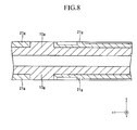
FIG. 8 ] Sectional view corresponding toFIG. 2 as viewed at the second stage in the process of manufacturing the structure of the fuel cell shown inFIG. 1 . - [
FIG. 9 ] Sectional view corresponding toFIG. 2 as viewed at the third stage in the process of manufacturing the structure of the fuel cell shown inFIG. 1 . - [
FIG. 10 ] Sectional view corresponding toFIG. 2 as viewed at the fourth stage in the process of manufacturing the structure of the fuel cell shown inFIG. 1 . - [
FIG. 11 ] Sectional view corresponding toFIG. 2 as viewed at the fifth stage in the process of manufacturing the structure of the fuel cell shown inFIG. 1 . - [
FIG. 12 ] Sectional view corresponding toFIG. 2 as viewed at the sixth stage in the process of manufacturing the structure of the fuel cell shown inFIG. 1 . - [
FIG. 13 ] Sectional view corresponding toFIG. 2 as viewed at the seventh stage in the process of manufacturing the structure of the fuel cell shown inFIG. 1 . - [
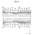
FIG. 14 ] Sectional view corresponding toFIG. 2 as viewed at the eighth stage in the process of manufacturing the structure of the fuel cell shown inFIG. 1 . - [
FIG. 15 ] Sectional view corresponding toFIG. 2 , showing a first modified embodiment of the structure of the fuel cell according to the present invention. - [
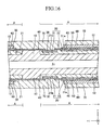
FIG. 16 ] Sectional view corresponding toFIG. 2 , showing a second modified embodiment of the structure of the fuel cell according to the present invention. - [
FIG. 17 ] Sectional view corresponding toFIG. 2 , showing a third modified embodiment of the structure of the fuel cell according to the present invention. - [
FIG. 18 ] Sectional view corresponding toFIG. 3 , showing a fourth modified embodiment of the structure of the fuel cell according to the present invention. -
FIG. 1 shows a structure of a solid oxide fuel cell (SOFC) according to an embodiment of the present invention. The SOFC structure has a configuration called a "segmented-in-series type" in which, on each of the upper and lower surfaces (opposite main surfaces (planes) parallel to each other) of a flat-plate-like support substrate 10 having a longitudinal direction (an x-axis direction), a plurality of (in the present embodiment, four) power-generating elements A having the same shape and connected electrically in series are disposed at predetermined intervals along the longitudinal direction. - As viewed from above, the entire SOFC structure has a rectangular shape with 5 cm to 50 cm on sides along the longitudinal direction and 1 cm to 10 cm on sides along a width direction (a y-axis direction) orthogonal to the longitudinal direction. The full thickness of the SOFC structure is 1 mm to 5 mm. The entire SOFC structure has a vertically symmetrical shape with respect to a plane which passes the center with respect to the thickness direction and is parallel to the main surfaces of the
support substrate 10. The SOFC structure will be described in detail below with reference to, in addition toFIG. 1 ,FIG. 2 , which is a fragmentary, sectional view of the SOFC structure taken along line 2-2 ofFIG. 1 .FIG. 2 is a fragmentary, sectional view showing the configurations (portions of the configurations) of a typical pair of adjacent power-generating elements A and a configuration between the power-generating elements A. The configurations between adjacent power-generating elements A of other pairs are similar to that shown inFIG. 2 . - The
support substrate 10 is a flat-plate-like sintered body of an electrically insulating porous material. As shown inFIG. 6 , which will be described later, thesupport substrate 10 has a plurality of (in the present embodiment, six) fuel gas flow channels 11 (through holes) formed therein, extending in the longitudinal direction, and disposed at predetermined intervals along the width direction. In the present embodiment, each ofrecesses 12 is a rectangular-parallelepiped-like depression defined by a bottom wall of the material of thesupport substrate 10 and side walls (two side walls along the longitudinal direction and two side walls along the width direction) of the material of thesupport substrate 10 arranged in a circumferentially closed manner. - The
support substrate 10 can be formed of, for example, CSZ (calcia-stabilized zirconia). Alternatively, thesupport substrate 10 may be formed of NiO (nickel oxide) and YSZ (8YSZ) (yttria-stabilized zirconia); NiO (nickel oxide) and Y2O3 (yttria); or MgO (magnesium oxide) and MgAl2O4 (magnesia alumina spinel). - The
support substrate 10 can contain "a transition metal oxide or a transition metal" and an insulating ceramic. NiO (nickel oxide) or Ni (nickel) is preferred as "a transition metal oxide or a transition metal." A transition metal can function as a catalyst for accelerating a reforming reaction of fuel gas (a reforming catalyst for hydrocarbonaceous gas). - A preferred insulating ceramic is MgO (magnesium oxide) or a "mixture of MgAl2O4 (magnesia alumina spinel) and MgO (magnesium oxide)." Also, CSZ (calcia-stabilized zirconia), YSZ (8YSZ) (yttria-stabilized zirconia), or Y2O3 (yttria) may be used as an insulating ceramic.
- In this manner, by means of the
support substrate 10 containing "a transition metal oxide or a transition metal," in a process in which gas that contains a residual unreformed gas component is supplied from the fuelgas flow channels 11 to the fuel electrodes through a large number of pores in theporous support substrate 10, the above-mentioned catalytic action can accelerate reforming of the residual unreformed gas component. Additionally, by means of thesupport substrate 10 containing an insulating ceramic, an insulating property of thesupport substrate 10 can be ensured. As a result, the insulation between the adjacent fuel electrodes can be ensured. - The thickness of the
support substrate 10 is 1 mm to 5 mm. In view that the structure has a vertically symmetrical shape, for simplification of description, only the upper configuration of thesupport substrate 10 will be described. The lower configuration of thesupport substrate 10 is similar to the upper configuration. - As shown in
FIGS. 2 and3 , fuel-electrode current-collectingportions 21 are embedded entirely in (filled into) therecesses 12 formed on the upper surface (the upper main surface) of thesupport substrate 10. Thus, each of the fuel-electrode current-collectingportions 21 assumes the form of a rectangular parallelepiped. Each of the fuel-electrode current-collectingportions 21 has arecess 21 a formed on its upper surface (outer surface). Each of therecesses 21 a is a rectangular-parallelepiped-like depression defined by a bottom wall of the material of the fuel-electrode current-collectingportion 21 and side walls (two side walls along the longitudinal direction and two side walls along the width direction) arranged in a circumferentially closed manner. Among the side walls arranged in a circumferentially closed manner, the two side walls along the longitudinal direction are of the material of thesupport substrate 10, and the two side walls along the width direction are of the material of the fuel-electrode current-collectingportion 21. - Fuel-electrode
active portions 22 are embedded entirely in (filled into) therespective recesses 21a. Thus, each of the fuel-electrodeactive portions 22 assumes the form of a rectangular parallelepiped. The fuel-electrode current-collectingportion 21 and the fuel-electrodeactive portion 22 constitute thefuel electrode 20. The fuel electrode 20 (the fuel-electrode current-collectingportion 21 + the fuel-electrode active portion 22) is a sintered body of a porous material having electron conductivity. Two side surfaces along the width direction and the bottom surface of each of the fuel-electrodeactive portions 22 are, within therecess 21 a, in contact with the fuel-electrode current-collectingportion 21. - On the upper surface (outer surface) of each of the fuel-electrode current-collecting
portions 21, arecess 21 b is formed in a region other than therecess 21 a. Each of therecesses 21 b is a rectangular-parallelepiped-like depression defined by a bottom wall of the material of the fuel-electrode current-collectingportion 21 and side walls (two side walls along the longitudinal direction and two side walls along the width direction) arranged in a circumferentially closed manner. Among the side walls arranged in a circumferentially closed manner, the two side walls along the longitudinal direction are of the material of thesupport substrate 10, and the two side walls along the width direction are of the material of the fuel-electrode current-collectingportion 21. -
Interconnectors 30 are embedded in (filled into) therespective recesses 21 b. Thus, each of theinterconnectors 30 assumes the form of a rectangular parallelepiped. Theinterconnector 30 is a sintered body of a dense material having electron conductivity. Two side surfaces along the width direction and the bottom surface of each of theinterconnectors 30 are, within therecess 21 b, in contact with the fuel-electrode current-collectingportion 21. - The upper surfaces (outer surfaces) of the fuel electrodes 20 (the fuel-electrode current-collecting
portions 21 and the fuel-electrode active portions 22), the upper surfaces (outer surfaces) of theinterconnectors 30, and the main surface of thesupport substrate 10 constitute a single plane (the same plane as the main surface of thesupport substrate 10 in the case where therecesses 12 are not formed). That is, no level difference exists among the upper surfaces of thefuel electrodes 20, the upper surfaces of theinterconnectors 30, and the main surface of thesupport substrate 10. - The fuel-electrode
active portion 22 can be formed of, for example, NiO (nickel oxide) and YSZ (8YSZ) (yttria-stabilized zirconia). Alternatively, the fuel-electrodeactive portion 22 may be formed of NiO (nickel oxide) and GDC (gadolinium-doped ceria). The fuel-electrode current-collectingportion 21 can be formed of, for example, NiO (nickel oxide) and YSZ (8YSZ) (yttria-stabilized zirconia). Alternatively, the fuel-electrode current-collectingportion 21 may be formed of NiO (nickel oxide) and Y2O3 (yttria), or NiO (nickel oxide) and CSZ (calcia-stabilized zirconia). The thickness of the fuel-electrodeactive portion 22 is 5 µm to 30 µm, and the thickness of the fuel-electrode current-collecting portion 21 (i.e., the depth of the recess 12) is 50 µm to 500 µm. - In this manner, the fuel-electrode current-collecting
portion 21 contains an electron-conductive substance. The fuel-electrodeactive portion 22 contains an electron-conductive substance and a substance having oxygen ion conductivity. "The ratio of the volume of a substance having oxygen ion conductivity to the total volume excluding pores" in the fuel-electrodeactive portion 22 is higher than "the ratio of the volume of a substance having oxygen ion conductivity to the total volume excluding pores" in the fuel-electrode current-collectingportion 21. - The
interconnector 30 is formed of, for example, LaCrO3 (lanthanum chromite). Alternatively, theinterconnector 30 may be formed of, (Sr, La)TiO3 (strontium titanate). The thickness of theinterconnector 30 is 10 µm to 100 µm. - A
solid electrolyte film 40 covers the entire longitudinally extending outer surface of an assembly of thesupport substrate 10 in which thefuel electrodes 20 and theinterconnectors 30 are embedded in therespective recesses 12, except for surface regions corresponding to longitudinally central portions of theinterconnectors 30. Thesolid electrolyte film 40 is a sintered body of a dense material having ion conductivity and not having electron conductivity. Thesolid electrolyte film 40 can be formed of, for example, YSZ (8YSZ) (yttria-stabilized zirconia). Alternatively, thesolid electrolyte film 40 may be formed of LSGM (lanthanum gallate). The thickness of thesolid electrolyte film 40 is 3 µm to 50 µm. - That is, a dense film composed of the
interconnectors 30 and thesolid electrolyte film 40 covers the entire longitudinally extending outer surface of the assembly of thesupport substrate 10 in which thefuel electrodes 20 are embedded in the respective recesses 12. This dense film performs a gas seal function of preventing the mixing of fuel gas flowing through a space on the inside of the dense layer and air flowing through a space on the outside of the dense layer. - As shown in
FIG. 2 , in the present embodiment, thesolid electrolyte film 40 covers the upper surfaces of thefuel electrodes 20, longitudinally opposite end portions of the upper surfaces of theinterconnectors 30, and the main surface of thesupport substrate 10. As mentioned above, no level difference exists among the upper surfaces of thefuel electrodes 20, the upper surfaces of theinterconnectors 30, and the main surface of thesupport substrate 10. Thus, thesolid electrolyte film 40 is flattened. As a result, as compared with the case where thesolid electrolyte film 40 involves a level difference, there can be restrained the generation of crack in thesolid electrolyte film 40 which could otherwise result from stress concentration, whereby deterioration in the gas seal function of thesolid electrolyte film 40 can be restrained. -
Air electrodes 60 are formed, via respectivereaction prevention films 50, on the respective upper surfaces of those portions of thesolid electrolyte film 40 which are in contact with the fuel-electrodeactive portions 22. Thereaction prevention film 50 is a sintered body of a dense material, and theair electrode 60 is a sintered body of a porous material having electron conductivity. As viewed from above, thereaction prevention film 50 and theair electrode 60 have a rectangular shape substantially similar to that of the fuel-electrodeactive portion 22. - The
reaction prevention film 50 can be formed of, for example, GDC = (Ce, Gd)O2 (gadolinium-doped ceria). The thickness of thereaction prevention film 50 is 3 µm to 50 µm. Theair electrode 60 can be formed of, for example, LSCF = (La, Sr)(Co, Fe)O3 (lanthanum strontium cobalt ferrite). Alternatively, theair electrode 60 may be formed of LSF = (La, Sr)FeO3 (lanthanum strontium ferrite), LNF = La(Ni, Fe)O3 (lanthanum nickel ferrite), LSC = (La, Sr)CoO3 (lanthanum strontium cobaltite), or the like. Also, theair electrode 60 may be of two layers consisting of a first layer (inner layer) of LSCF and a second layer (outer layer) of LSC. The thickness of theair electrode 60 is 10 µm to 100 µm. - The reason for using the
reaction prevention film 50 as an intervening film is to restrain the occurrence of the phenomenon that, in the course of fabrication or operation of an SOFC, YSZ in thesolid electrolyte film 40 and Sr in theair electrode 60 react with each other to form a reaction film having a high electric resistance at the interface between thesolid electrolyte film 40 and theair electrode 60. - A laminate of the
fuel electrode 20, thesolid electrolyte film 40, thereaction prevention film 50, and theair electrode 60 corresponds to the "power-generating element A" (seeFIG. 2 ). That is, on the upper surface of thesupport substrate 10, a plurality of (in the present embodiment, four) the power-generating elements A are disposed at predetermined intervals along the longitudinal direction. - In each pair of the adjacent power-generating elements A, an air-electrode current-collecting
film 70 is formed on the upper surfaces of theair electrode 60, thesolid electrolyte film 40, and theinterconnector 30 in such a manner as to bridge theair electrode 60 of one (inFIG. 2 , the left) power-generating element A and theinterconnector 30 of the other (inFIG. 2 , the right) power-generating element A. The air-electrode current-collectingfilm 70 is a sintered body of a porous material having electron conductivity. As viewed from above, the air-electrode current-collectingfilm 70 has a rectangular shape. - The air-electrode current-collecting
film 70 can be formed of, for example, LSCF = (La, Sr)(Co, Fe)O3 (lanthanum strontium cobalt ferrite). Alternatively, the air-electrode current-collectingfilm 70 may be formed of LSC = (La, Sr)CoO3 (lanthanum strontium cobaltite). Alternatively, the air-electrode current-collectingfilm 70 may be formed of Ag (silver) or Ag-Pd (silver-palladium alloy). The thickness of the air-electrode current-collectingfilm 70 is 50 µm to 500 µm. - In this manner, through formation of the air-electrode current-collecting
films 70, in each pair of the adjacent power-generating elements A, theair electrode 60 of one (inFIG. 2 , the left) power-generating element A and the fuel electrode 20 (particularly, the fuel-electrode current-collecting portion 21) of the other (inFIG. 2 , the right) power-generating element A are electrically connected to each other via "the air-electrode current-collectingfilm 70 and theinterconnector 30" having electron conductivity. As a result, a plurality of (in the present embodiment, four) power-generating elements A disposed on the upper surface of thesupport substrate 10 are connected electrically in series. "The air-electrode current-collectingfilm 70 and theinterconnector 30" having electron conductivity collectively correspond to the aforementioned "electrical connection." - The
interconnector 30 corresponds to the aforementioned "first portion formed of a dense material" of the "electrical connection" and has a porosity of 10% or less. The air-electrode current-collectingfilm 70 corresponds to the aforementioned "second portion formed of a porous material" of the "electrical connection" and has a porosity of 20% to 60%. - In the above-described "segmented-in-series type" SOFC structure, as shown in
FIG. 4 , fuel gas (hydrogen gas or the like) is run through the fuelgas flow channels 11 of thesupport substrate 10, and the upper and lower surfaces of the support substrate 10 (particularly the air-electrode current-collecting films 70) are exposed to "gas containing oxygen" (air or the like) (alternatively, gas containing oxygen is run along the upper and lower surfaces of the support substrate 10), whereby electromotive force is generated according to the difference in partial pressure of oxygen between the opposite surfaces of thesolid electrolyte film 40. Furthermore, when this structure is connected to an external load, the chemical reactions expressed by the following Formulae (1) and (2) occur, and current flows (power generating condition).
(1/2). O2 + 2e- → O2- (at the air electrode 60) (1)
H2 + O2- → H2O + 2e- (at the fuel electrode 20) (2)
- In the power generating condition, as shown in
FIG. 5 , in each pair of the adjacent power-generating elements A, current flows as indicated by the arrows. As a result, power is output from the entire SOFC structure as shown inFIG. 4 (specifically, via theinterconnector 30 of the power-generating element A located on the nearest side inFIG. 4 and theair electrode 60 of the power-generating element A located on the farthest side inFIG. 4 ). - Next, an example method for manufacturing the "segmented-in-series type" SOFC structure shown in
FIG. 1 will be briefly described with reference toFIGS. 6 to 14 . InFIGS. 6 to 14 , the trailing letter "g" of reference numerals of members indicates that the members are "green." - First, a
green body 10g of the support substrate having a shape shown inFIG. 6 is manufactured. Thegreen body 10g of the support substrate can be manufactured, for example, by use of a slurry prepared by adding a binder, etc., to a powder of a material (e.g., CSZ) of thesupport substrate 10 and through utilization of extrusion, machining, and like working processes. The description of the method continues below with reference toFIGS. 7 to 14 , which are fragmentary sectional views taken along line 7-7 ofFIG. 6 . - After the
green body 10g of the support substrate is manufactured as shown inFIG. 7 , as shown inFIG. 8 ,green bodies 21g of the fuel-electrode current-collecting portions are formed in an embedded manner in respective recesses formed on the upper and lower surfaces of thegreen body 10g of the support substrate. Next, as shown inFIG. 9 ,green bodies 22g of the fuel-electrode active portions are formed in an embedded manner in the respective recesses formed on the outer surfaces of thegreen bodies 21 g of the fuel-electrode current-collecting portions. Thegreen bodies 21g of the fuel-electrode current-collecting portions and the fuel-electrodeactive portions 22g are formed in an embedded manner, for example, by use of a slurry prepared by adding a binder, etc., to a powder of a material (e.g., Ni and YSZ) of thefuel electrode 20 and through utilization of a printing process, or the like. - Subsequently, as shown in
FIG. 10 ,green bodies 30g of the interconnectors are formed in an embedded manner in respective recesses which are formed on the outer surfaces of thegreen bodies 21g of the fuel-electrode current-collecting portions in "regions other than those where thegreen bodies 22g of the fuel-electrode active portions are embedded." Thegreen bodies 30g of the interconnectors are formed in an embedded manner, for example, by use of a slurry prepared by adding a binder, etc., to a power of a material (e.g., LaCrO3) of theinterconnector 30 and through utilization of a printing process or the like. - Next, as shown in
FIG. 11 , agreen film 40g of the solid electrolyte film is formed on the entire longitudinally extending outer surface of an assembly of thegreen body 10g of the support substrate in which a plurality of the green bodies (21g + 22g) of the fuel electrodes and a plurality of thegreen bodies 30g of the interconnectors are formed in an embedded manner, except for surface regions corresponding to longitudinally central portions of thegreen bodies 30g of the interconnectors. Thegreen film 40g of the solid electrolyte film is formed, for example, by use of a slurry prepared by adding a binder, etc., to a powder of a material (e.g., YSZ) of thesolid electrolyte film 40 and through utilization of a printing process, a dipping process, or the like. - Next, as shown in
FIG. 12 ,green films 50g of the reaction prevention films are formed on the respective upper surfaces of those portions of thegreen body 40g of the solid electrolyte film which are in contact with thegreen bodies 22g of the fuel electrodes. Thegreen films 50g of the reaction prevention films are formed, for example, by use of a slurry prepared by adding a binder, etc., to a powder of a material (e.g., GDC) of thereaction prevention film 50 and through utilization of a printing process or the like. - Then, the
green body 10g of the support substrate on which such various green films are formed is sintered at 1,500°C for three hours in air. By this procedure, there is yielded a structure in a state in which theair electrodes 60 and the air-electrode current-collectingfilms 70 are removed from the SOFC structure shown inFIG. 1 . - Next, as shown in
FIG. 13 ,green films 60g of the air electrodes are formed on the outer surfaces of thereaction prevention films 50, respectively. Thegreen films 60g of the air electrodes are formed, for example, by use of a slurry prepared by adding a binder, etc., to a powder of a material (e.g., LSCF) of theair electrode 60 and through utilization of a printing process or the like. - Next, as shown in
FIG. 14 , in each pair of the adjacent power-generating elements, agreen film 70g of the air-electrode current-collecting film is formed on the upper surface of thegreen film 60g of the air electrode, the upper surface of thesolid electrolyte film 40, and the upper surface of the interconnector 30 in such a manner as to bridge thegreen film 60g of the air electrode of one power-generating element and theinterconnector 30 of the other power-generating element. Thegreen films 70g of the air-electrode current-collecting films are formed, for example, by use of a slurry prepared by adding a binder, etc., to a powder of a material (e.g., LSCF) of the air-electrode current-collectingfilm 70 and through utilization of a printing process or the like. - Then, the
support substrate 10 in a state in which thegreen films FIG. 1 is yielded. So far, an example method for manufacturing the SOFC structure shown inFIG. 1 has been described. - As described above, in the "segmented-in-series type" SOFC structure according to the above embodiment of the present invention, each of a plurality of the
recesses 12 formed on the upper and lower surfaces of thesupport substrate 10 and adapted to allow therespective fuel electrodes 20 to be embedded therein has side walls of the material of thesupport substrate 10 arranged in a circumferentially closed manner. In other words, in thesupport substrate 10, frames which surround therespective recesses 12 are formed. Thus, this structure is unlikely to be deformed when thesupport substrate 10 is subjected to an external force. - In a state in which members, such as the
fuel electrodes 20 and theinterconnectors 30, are tightly filled or embedded into therespective recesses 12 of thesupport substrate 10, thesupport substrate 10 and the embedded members are cosintered. Thus, there is yielded a sintered body having high bonding strength between members and high reliability. - Also, each of the
interconnectors 30 is embedded in therecess 21 b formed on the outer surface of the fuel-electrode current-collection portion 21. As a result, two side surfaces along the width direction (y-axis direction) and the bottom surface of the rectangular-parallelepiped-like interconnector 30 are, within therecess 21 b, in contact with the fuel-electrode current-collectingportion 21. Thus, as compared with a configuration in which each of the rectangular-parallelepiped-like interconnectors 30 is laminated on (in contact with) the outer plane of the fuel-electrode current-collectingportion 21, the area of the interface between the fuel electrode 20 (the current-collecting portion 21) and theinterconnector 30 can be increased. Thus, electron conductivity between thefuel electrode 20 and theinterconnector 30 can be enhanced; as a result, the power output of the fuel cell can be increased. - Also, in the above-described embodiment, a plurality of the power-generating elements A are provided on each of the upper and lower surfaces of the flat-plate-
like support substrate 10. Thus, as compared with the case where a plurality of the power-generating elements are provided on only one side of the support substrate, the number of the power-generating elements in the structure can be increased, whereby the power output of the fuel cell can be increased. - In the above-described embodiment, the
solid electrolyte film 40 covers the outer surfaces of thefuel electrodes 20, longitudinally opposite end portions of the outer surfaces of theinterconnectors 30, and the main surface of thesupport substrate 10. Meanwhile, no level difference exists among the outer surfaces of thefuel electrodes 20, the outer surfaces of theinterconnectors 30, and the main surface of thesupport substrate 10. Thus, thesolid electrolyte film 40 is flattened. As a result, as compared with the case where thesolid electrolyte film 40 involves a level difference, there can be restrained the generation of crack in thesolid electrolyte film 40 which could otherwise result from stress concentration, whereby deterioration in the gas seal function of thesolid electrolyte film 40 can be restrained. - The present invention is not limited to the above-described embodiment, but may be modified in various other forms within the scope of the invention. For example, in the above embodiment, as shown in
FIG. 6 , etc., the planar shape (a shape as viewed from a direction perpendicular to the main surface of the support substrate 10) of therecess 12 formed in thesupport substrate 10 is a rectangular shape. However, the planar shape may be, for example, a square shape, a circular shape, an elliptic shape, or an elongated-hole shape. - Similarly, as shown in
FIG. 3 , etc., the planar shape (a shape as viewed from a direction perpendicular to the main surface of the support substrate 10) of therecess 21 b formed in the fuel electrode 20 (the current-collecting portion 21) is a rectangular shape. However, the planar shape may be, for example, a square shape, a circular shape, an elliptic shape, or an elongated-hole shape. Therecess 21 b partially shares the side wall with therecess 12. That is, the side wall (circumferentially closed) of therecess 21 b is partially of the material of the fuel electrode 20 (the current-collecting portion 21) and is partially of the material of thesupport substrate 10. - Also, in the above-described embodiment, the
interconnector 30 is entirely embedded in each of therecesses 12. However, only a portion of theinterconnector 30 may be embedded in each of therecesses 12 while the remaining portion of the interconnector 30 projects outward from the recess 12 (i.e., the remaining portion projects from the main surface of the support substrate 10). - Also, in the above-described embodiment, the bottom wall and the side wall of the
recess 12 forms an angle θ of 90°. However, as shown inFIG. 15 , the angle θ may be 90° to 135°. Also, in the above embodiment, as shown inFIG. 16 , the bottom wall and the side wall of therecess 12 may intersect with each other along an arc having a radius R such that the ratio of the radius R to the depth of therecess 12 is 0.01 to 1. - Also, in the above-described embodiment, the flat-plate-
like support substrate 10 has a plurality of therecesses 12 formed on and a plurality of the power-generating elements A provided on each of the upper and lower surfaces thereof. However, as shown inFIG. 17 , thesupport substrate 10 may have a plurality of therecesses 12 formed on and a plurality of the power-generating elements A provided on only the surface on one side thereof. - In the above-described embodiment, the
fuel electrode 20 is configured in two layers consisting of the fuel-electrode current-collectingportion 21 and a fuel-electrodeactive portion 22. However, thefuel electrode 20 may be configured in a single layer equivalent to the fuel-electrodeactive portion 22. Additionally, in the above embodiment, the "inner electrode" and the "outer electrode" are the fuel electrode and the air electrode, respectively. However, they may be reversed. - Additionally, in the above-described embodiment, as shown in
FIG. 3 , therecess 21 b formed on the outer surface of the fuel-electrode current-collectingportion 21 is a rectangular-parallelepiped-like depression defined by the bottom wall of the material of the fuel-electrode current-collectingportion 21 and the side walls (two side walls of the material of thesupport substrate 10 extending along the longitudinal direction and two side walls of the material of the fuel-electrode current-collectingportion 21 extending along the width direction) arranged in a circumferentially closed manner. As a result, two side surfaces along the width direction and the bottom surface of the interconnector 30 embedded in therecess 21 b are, within therecess 21 b, in contact with the fuel-electrode current-collectingportion 21. - Meanwhile, as shown in
FIG. 18 , therecess 21 b formed on the outer surface of the fuel-electrode current-collectingportion 21 may be a rectangular-parallelepiped-like depression defined by the bottom wall of the material of the fuel-electrode current-collectingportion 21 and the side walls (two side walls along the longitudinal direction and two side walls along the width direction) of the material of the fuel-electrode current-collectingportion 21 arranged in a circumferentially closed manner. According to this feature, the bottom surface and all of the four side surfaces of the interconnector 30 embedded in therecess 21 b are, within therecess 21 b, in contact with the fuel-electrode current-collectingportion 21. Thus, the area of the interface between the fuel-electrode current-collectingportion 21 and theinterconnector 30 can be further increased. Therefore, the electron conductivity between the fuel-electrode current-collectingportion 21 and theinterconnector 30 can be further enhanced; as a result, the power output of the fuel cell can be further increased.
Claims (5)
- A structure of a fuel cell comprising:a flat-plate-like porous support substrate (10) having a gas flow channel (11) formed therein;a plurality of power-generating elements provided on a main surface of the flat-plate-like support substrate (10) at a plurality of positions, respectively, located apart from one another, each of the power-generating elements being a laminate of at least an inner electrode (20), a solid electrolyte (40), and an outer electrode (60); anda single or a plurality of electrical connections provided between a pair of or pairs of adjacent power-generating elements and adapted to electrically connect the inner electrode (20) of one of the adjacent power-generating elements and the outer electrode (60) of the other one of the adjacent power-generating elements;wherein each of the electrical connections is composed of a first portion (30) formed of a dense material and a second portion (70) connected to the first portion (30) and formed of a porous material;first recesses (12) are formed on the main surface of the flat-plate-like support substrate (10) at the plurality of positions, respectively, each of the first recesses (12) having a bottom wall formed of a material of the support substrate (10) and a circumferentially closed side wall entirely formed of the material of the support substrate (10);the inner electrodes (20) of the power-generating elements are embedded in the corresponding first recesses (12);second recesses (21b) are formed on outer surfaces of the embedded inner electrodes (20), each of the second recesses (21b) having a bottom wall formed of a material of the inner electrodes (20) and a circumferentially closed side wall having a portion formed of the material of the inner electrodes (20); andthe first portions (30) of the electrical connections are embedded in the corresponding second recesses (21b);wherein the circumferentially closed side wall of each of the second recesses (21b) is entirely formed of the material of the inner electrode (20).
- A structure of a fuel cell according to claim 1, wherein outer surfaces of the inner electrodes (20), excluding the second recesses (21b), outer surfaces of the first portions of the electrical connections (30), and the main surface of the support substrate (10)constitute a single plane.
- A structure of a fuel cell according to claim 1 or 2, wherein a flat portion of the bottom wall and a flat portion of the side wall of each of the first recesses (12) form an angle of 90° to 135°.
- A structure of a fuel cell according to any one of claims 1 to 3, wherein a flat portion of the bottom wall and a flat portion of the side wall of each of the first recesses (12) intersect with each other along an arc, and the ratio of a radius of the arc to a depth of the first recess (12) is 0.01 to 1.
- A structure of a fuel cell according to any one of claims 1 to 4, wherein the plurality of first recesses (12) are formed on each of opposite, parallel main surfaces of the flat-plate-like support substrate (10);
the inner electrodes (20) of the power-generating elements are embedded in the respective first recesses (12) formed on the opposite main surfaces of the support substrate (10); and
the first portions (30) of the electrical connections are embedded in the respective second recesses (21b) formed on the outer surfaces of the embedded inner electrodes (20),
whereby the plurality of power-generating elements are provided on the opposite main surfaces of the support substrate (10).
Applications Claiming Priority (3)
| Application Number | Priority Date | Filing Date | Title |
|---|---|---|---|
| JP2010160505 | 2010-07-15 | ||
| JP2011090363A JP4824135B1 (en) | 2010-07-15 | 2011-04-14 | Fuel cell structure |
| PCT/JP2011/065730 WO2012008386A1 (en) | 2010-07-15 | 2011-07-08 | Fuel cell structural body |
Publications (3)
| Publication Number | Publication Date |
|---|---|
| EP2595230A1 EP2595230A1 (en) | 2013-05-22 |
| EP2595230A4 EP2595230A4 (en) | 2013-09-25 |
| EP2595230B1 true EP2595230B1 (en) | 2014-11-12 |
Family
ID=44946822
Family Applications (1)
| Application Number | Title | Priority Date | Filing Date |
|---|---|---|---|
| EP11806716.4A Active EP2595230B1 (en) | 2010-07-15 | 2011-07-08 | Fuel cell structural body |
Country Status (5)
| Country | Link |
|---|---|
| US (1) | US8703352B2 (en) |
| EP (1) | EP2595230B1 (en) |
| JP (6) | JP4800439B1 (en) |
| CN (1) | CN103081199B (en) |
| WO (1) | WO2012008386A1 (en) |
Families Citing this family (30)
| Publication number | Priority date | Publication date | Assignee | Title |
|---|---|---|---|---|
| CN102986075B (en) * | 2010-07-15 | 2015-08-26 | 日本碍子株式会社 | The structure of fuel cell |
| JP5075268B1 (en) * | 2011-07-21 | 2012-11-21 | 日本碍子株式会社 | Fuel cell structure |
| JP5095877B1 (en) * | 2011-10-05 | 2012-12-12 | 日本碍子株式会社 | Fuel cell |
| JP5116181B1 (en) * | 2011-10-14 | 2013-01-09 | 日本碍子株式会社 | Fuel cell stack structure |
| JP5050124B1 (en) * | 2011-10-25 | 2012-10-17 | 日本碍子株式会社 | Fuel cell structure |
| JP5117627B1 (en) * | 2011-10-25 | 2013-01-16 | 日本碍子株式会社 | Fuel cell structure |
| JP5417548B2 (en) * | 2012-06-26 | 2014-02-19 | 日本碍子株式会社 | Fuel cell structure |
| JP5369229B1 (en) * | 2012-09-06 | 2013-12-18 | 日本碍子株式会社 | Fuel cell |
| JP5632518B2 (en) * | 2012-09-14 | 2014-11-26 | 日本碍子株式会社 | Fuel cell |
| JP2014165000A (en) * | 2013-02-25 | 2014-09-08 | Kyocera Corp | Solid oxide fuel cell |
| JP6039459B2 (en) * | 2013-02-26 | 2016-12-07 | 京セラ株式会社 | Solid oxide fuel cell |
| JP5551803B1 (en) * | 2013-02-27 | 2014-07-16 | 日本碍子株式会社 | Fuel cell and fuel cell stack structure |
| JP6039463B2 (en) * | 2013-02-28 | 2016-12-07 | 京セラ株式会社 | Solid oxide fuel cell |
| JP6075924B2 (en) * | 2013-09-13 | 2017-02-08 | 株式会社日本自動車部品総合研究所 | Fuel cell single cell and manufacturing method thereof |
| JP6088949B2 (en) * | 2013-09-13 | 2017-03-01 | 株式会社日本自動車部品総合研究所 | Fuel cell single cell and manufacturing method thereof |
| JP5621029B1 (en) * | 2013-09-24 | 2014-11-05 | 日本碍子株式会社 | Fuel cell |
| JP6169930B2 (en) * | 2013-09-25 | 2017-07-26 | 京セラ株式会社 | Solid oxide fuel cell |
| JP6301790B2 (en) * | 2014-09-12 | 2018-03-28 | 京セラ株式会社 | Horizontally striped solid oxide fuel cell |
| JP5895113B1 (en) * | 2015-01-07 | 2016-03-30 | 日本碍子株式会社 | Fuel cell |
| JP5895112B1 (en) * | 2015-01-07 | 2016-03-30 | 日本碍子株式会社 | Fuel cell |
| JP6026044B1 (en) | 2015-07-03 | 2016-11-16 | 日本碍子株式会社 | Fuel cell stack |
| CN108352541B (en) * | 2015-11-18 | 2021-12-24 | 英钒能源(加拿大)公司 | Flow battery with improved electrode assembly and electrolyte distribution |
| JP6335233B2 (en) * | 2016-09-05 | 2018-05-30 | 日本碍子株式会社 | Fuel cell |
| JP6427652B2 (en) * | 2016-12-09 | 2018-11-21 | 日本碍子株式会社 | Fuel cell |
| RU2692688C2 (en) * | 2017-12-04 | 2019-06-26 | Федеральное государственное бюджетное учреждение науки Институт электрофизики Уральского отделения Российской академии наук (ИЭФ УрО РАН) | Micro-planar solid oxide element (mpsoe), battery based on mpsoe (versions) |
| WO2019188685A1 (en) | 2018-03-28 | 2019-10-03 | 京セラ株式会社 | Solid oxide fuel cell |
| WO2019208187A1 (en) | 2018-04-26 | 2019-10-31 | 京セラ株式会社 | Solid oxide fuel battery cell |
| JP6518821B1 (en) * | 2018-06-06 | 2019-05-22 | 日本碍子株式会社 | Cell stack device |
| US11495820B2 (en) | 2018-07-27 | 2022-11-08 | Kyocera Corporation | Fuel battery cell and cell stack device |
| JP6559372B1 (en) * | 2018-09-07 | 2019-08-14 | 日本碍子株式会社 | Alloy member, cell stack and cell stack apparatus |
Family Cites Families (15)
| Publication number | Priority date | Publication date | Assignee | Title |
|---|---|---|---|---|
| JPH05166531A (en) * | 1991-12-12 | 1993-07-02 | Yoshida Kogyo Kk <Ykk> | Manufacture of solid electrolyte fuel cell |
| JPH0668900A (en) * | 1992-08-13 | 1994-03-11 | Yoshida Kogyo Kk <Ykk> | Solid electrolytic fuel cell generator |
| JPH08106916A (en) * | 1994-10-03 | 1996-04-23 | Mitsubishi Heavy Ind Ltd | Solid electrolyte fuel cell |
| JP3233807B2 (en) * | 1995-02-15 | 2001-12-04 | 三菱重工業株式会社 | Substrate material for solid oxide fuel cells |
| EP1603183B1 (en) | 2003-03-13 | 2010-09-01 | Tokyo Gas Company Limited | Solid-oxide shaped fuel cell module |
| JP4368850B2 (en) * | 2003-03-31 | 2009-11-18 | 東京瓦斯株式会社 | Method for producing solid oxide fuel cell module |
| JP3914990B2 (en) * | 2003-11-18 | 2007-05-16 | 独立行政法人産業技術総合研究所 | Cylindrical fuel cell |
| JP4718772B2 (en) * | 2003-12-10 | 2011-07-06 | 三菱重工業株式会社 | Solid oxide fuel cell, water electrolysis cell, and method for producing solid oxide fuel cell |
| JP4776930B2 (en) * | 2004-04-28 | 2011-09-21 | 東京瓦斯株式会社 | Support substrate for solid oxide fuel cell |
| JP4593997B2 (en) * | 2004-07-28 | 2010-12-08 | 京セラ株式会社 | Support for fuel cell, fuel cell, and fuel cell |
| JP4815815B2 (en) * | 2005-02-08 | 2011-11-16 | 大日本印刷株式会社 | Single-chamber solid oxide fuel cell |
| JP2007103092A (en) * | 2005-09-30 | 2007-04-19 | Dainippon Printing Co Ltd | Solid oxide fuel cell |
| US20080286630A1 (en) * | 2005-11-23 | 2008-11-20 | Jacobson Craig P | Electrochemical Cell Holder and Stack |
| JP5000158B2 (en) * | 2006-03-14 | 2012-08-15 | 東京瓦斯株式会社 | Solid oxide fuel cell stack and manufacturing method thereof |
| JP5118865B2 (en) * | 2007-03-15 | 2013-01-16 | 京セラ株式会社 | Horizontally-striped fuel cell and method for producing the same |
-
2010
- 2010-12-21 JP JP2010284284A patent/JP4800439B1/en active Active
- 2010-12-21 JP JP2010284285A patent/JP2012038701A/en active Pending
-
2011
- 2011-04-14 JP JP2011090363A patent/JP4824135B1/en active Active
- 2011-07-08 JP JP2011151492A patent/JP4828663B1/en active Active
- 2011-07-08 JP JP2011151498A patent/JP4828664B1/en active Active
- 2011-07-08 CN CN201180004686.6A patent/CN103081199B/en active Active
- 2011-07-08 US US13/178,889 patent/US8703352B2/en active Active
- 2011-07-08 WO PCT/JP2011/065730 patent/WO2012008386A1/en active Application Filing
- 2011-07-08 JP JP2011151489A patent/JP4850980B1/en active Active
- 2011-07-08 EP EP11806716.4A patent/EP2595230B1/en active Active
Also Published As
| Publication number | Publication date |
|---|---|
| JP4850980B1 (en) | 2012-01-11 |
| JP2012038706A (en) | 2012-02-23 |
| CN103081199B (en) | 2015-01-07 |
| JP2012038717A (en) | 2012-02-23 |
| CN103081199A (en) | 2013-05-01 |
| JP4824135B1 (en) | 2011-11-30 |
| JP2012038718A (en) | 2012-02-23 |
| US8703352B2 (en) | 2014-04-22 |
| JP2012038701A (en) | 2012-02-23 |
| JP2012038720A (en) | 2012-02-23 |
| JP4828664B1 (en) | 2011-11-30 |
| JP4800439B1 (en) | 2011-10-26 |
| US20120107715A1 (en) | 2012-05-03 |
| EP2595230A4 (en) | 2013-09-25 |
| JP4828663B1 (en) | 2011-11-30 |
| WO2012008386A1 (en) | 2012-01-19 |
| JP2012124134A (en) | 2012-06-28 |
| EP2595230A1 (en) | 2013-05-22 |
Similar Documents
| Publication | Publication Date | Title |
|---|---|---|
| EP2595230B1 (en) | Fuel cell structural body | |
| EP2658019B1 (en) | Junction for electrically connecting power generation units of solid oxide fuel cell | |
| JP5116184B1 (en) | Fuel cell structure | |
| EP2592682B1 (en) | Fuel cell structural body | |
| JP4883733B1 (en) | Fuel cell structure | |
| JP4824137B1 (en) | Fuel cell structure | |
| JP4846061B1 (en) | Fuel cell structure | |
| JP5116182B1 (en) | Fuel cell structure | |
| JP4902013B1 (en) | Fuel cell | |
| JP5075268B1 (en) | Fuel cell structure | |
| JP6169932B2 (en) | Solid oxide fuel cell | |
| JP5050124B1 (en) | Fuel cell structure | |
| JP5417548B2 (en) | Fuel cell structure | |
| JP4824136B1 (en) | Fuel cell structure |
Legal Events
| Date | Code | Title | Description |
|---|---|---|---|
| PUAI | Public reference made under article 153(3) epc to a published international application that has entered the european phase |
Free format text: ORIGINAL CODE: 0009012 |
|
| 17P | Request for examination filed |
Effective date: 20120312 |
|
| AK | Designated contracting states |
Kind code of ref document: A1 Designated state(s): AL AT BE BG CH CY CZ DE DK EE ES FI FR GB GR HR HU IE IS IT LI LT LU LV MC MK MT NL NO PL PT RO RS SE SI SK SM TR |
|
| A4 | Supplementary search report drawn up and despatched |
Effective date: 20130828 |
|
| RIC1 | Information provided on ipc code assigned before grant |
Ipc: H01M 8/02 20060101ALI20130822BHEP Ipc: H01M 8/24 20060101AFI20130822BHEP Ipc: H01M 8/12 20060101ALI20130822BHEP |
|
| DAX | Request for extension of the european patent (deleted) | ||
| GRAP | Despatch of communication of intention to grant a patent |
Free format text: ORIGINAL CODE: EPIDOSNIGR1 |
|
| INTG | Intention to grant announced |
Effective date: 20140523 |
|
| GRAS | Grant fee paid |
Free format text: ORIGINAL CODE: EPIDOSNIGR3 |
|
| GRAA | (expected) grant |
Free format text: ORIGINAL CODE: 0009210 |
|
| AK | Designated contracting states |
Kind code of ref document: B1 Designated state(s): AL AT BE BG CH CY CZ DE DK EE ES FI FR GB GR HR HU IE IS IT LI LT LU LV MC MK MT NL NO PL PT RO RS SE SI SK SM TR |
|
| REG | Reference to a national code |
Ref country code: GB Ref legal event code: FG4D |
|
| REG | Reference to a national code |
Ref country code: CH Ref legal event code: EP |
|
| REG | Reference to a national code |
Ref country code: AT Ref legal event code: REF Ref document number: 696228 Country of ref document: AT Kind code of ref document: T Effective date: 20141115 |
|
| REG | Reference to a national code |
Ref country code: IE Ref legal event code: FG4D |
|
| REG | Reference to a national code |
Ref country code: DE Ref legal event code: R096 Ref document number: 602011011404 Country of ref document: DE Effective date: 20141224 |
|
| REG | Reference to a national code |
Ref country code: NL Ref legal event code: VDEP Effective date: 20141112 |
|
| REG | Reference to a national code |
Ref country code: AT Ref legal event code: MK05 Ref document number: 696228 Country of ref document: AT Kind code of ref document: T Effective date: 20141112 |
|
| PG25 | Lapsed in a contracting state [announced via postgrant information from national office to epo] |
Ref country code: PT Free format text: LAPSE BECAUSE OF FAILURE TO SUBMIT A TRANSLATION OF THE DESCRIPTION OR TO PAY THE FEE WITHIN THE PRESCRIBED TIME-LIMIT Effective date: 20150312 Ref country code: ES Free format text: LAPSE BECAUSE OF FAILURE TO SUBMIT A TRANSLATION OF THE DESCRIPTION OR TO PAY THE FEE WITHIN THE PRESCRIBED TIME-LIMIT Effective date: 20141112 Ref country code: IS Free format text: LAPSE BECAUSE OF FAILURE TO SUBMIT A TRANSLATION OF THE DESCRIPTION OR TO PAY THE FEE WITHIN THE PRESCRIBED TIME-LIMIT Effective date: 20150312 Ref country code: FI Free format text: LAPSE BECAUSE OF FAILURE TO SUBMIT A TRANSLATION OF THE DESCRIPTION OR TO PAY THE FEE WITHIN THE PRESCRIBED TIME-LIMIT Effective date: 20141112 Ref country code: LT Free format text: LAPSE BECAUSE OF FAILURE TO SUBMIT A TRANSLATION OF THE DESCRIPTION OR TO PAY THE FEE WITHIN THE PRESCRIBED TIME-LIMIT Effective date: 20141112 Ref country code: NL Free format text: LAPSE BECAUSE OF FAILURE TO SUBMIT A TRANSLATION OF THE DESCRIPTION OR TO PAY THE FEE WITHIN THE PRESCRIBED TIME-LIMIT Effective date: 20141112 Ref country code: NO Free format text: LAPSE BECAUSE OF FAILURE TO SUBMIT A TRANSLATION OF THE DESCRIPTION OR TO PAY THE FEE WITHIN THE PRESCRIBED TIME-LIMIT Effective date: 20150212 |
|
| PG25 | Lapsed in a contracting state [announced via postgrant information from national office to epo] |
Ref country code: GR Free format text: LAPSE BECAUSE OF FAILURE TO SUBMIT A TRANSLATION OF THE DESCRIPTION OR TO PAY THE FEE WITHIN THE PRESCRIBED TIME-LIMIT Effective date: 20150213 Ref country code: LV Free format text: LAPSE BECAUSE OF FAILURE TO SUBMIT A TRANSLATION OF THE DESCRIPTION OR TO PAY THE FEE WITHIN THE PRESCRIBED TIME-LIMIT Effective date: 20141112 Ref country code: HR Free format text: LAPSE BECAUSE OF FAILURE TO SUBMIT A TRANSLATION OF THE DESCRIPTION OR TO PAY THE FEE WITHIN THE PRESCRIBED TIME-LIMIT Effective date: 20141112 Ref country code: PL Free format text: LAPSE BECAUSE OF FAILURE TO SUBMIT A TRANSLATION OF THE DESCRIPTION OR TO PAY THE FEE WITHIN THE PRESCRIBED TIME-LIMIT Effective date: 20141112 Ref country code: CY Free format text: LAPSE BECAUSE OF FAILURE TO SUBMIT A TRANSLATION OF THE DESCRIPTION OR TO PAY THE FEE WITHIN THE PRESCRIBED TIME-LIMIT Effective date: 20141112 Ref country code: SE Free format text: LAPSE BECAUSE OF FAILURE TO SUBMIT A TRANSLATION OF THE DESCRIPTION OR TO PAY THE FEE WITHIN THE PRESCRIBED TIME-LIMIT Effective date: 20141112 Ref country code: RS Free format text: LAPSE BECAUSE OF FAILURE TO SUBMIT A TRANSLATION OF THE DESCRIPTION OR TO PAY THE FEE WITHIN THE PRESCRIBED TIME-LIMIT Effective date: 20141112 Ref country code: AT Free format text: LAPSE BECAUSE OF FAILURE TO SUBMIT A TRANSLATION OF THE DESCRIPTION OR TO PAY THE FEE WITHIN THE PRESCRIBED TIME-LIMIT Effective date: 20141112 |
|
| PG25 | Lapsed in a contracting state [announced via postgrant information from national office to epo] |
Ref country code: DK Free format text: LAPSE BECAUSE OF FAILURE TO SUBMIT A TRANSLATION OF THE DESCRIPTION OR TO PAY THE FEE WITHIN THE PRESCRIBED TIME-LIMIT Effective date: 20141112 Ref country code: EE Free format text: LAPSE BECAUSE OF FAILURE TO SUBMIT A TRANSLATION OF THE DESCRIPTION OR TO PAY THE FEE WITHIN THE PRESCRIBED TIME-LIMIT Effective date: 20141112 Ref country code: RO Free format text: LAPSE BECAUSE OF FAILURE TO SUBMIT A TRANSLATION OF THE DESCRIPTION OR TO PAY THE FEE WITHIN THE PRESCRIBED TIME-LIMIT Effective date: 20141112 Ref country code: CZ Free format text: LAPSE BECAUSE OF FAILURE TO SUBMIT A TRANSLATION OF THE DESCRIPTION OR TO PAY THE FEE WITHIN THE PRESCRIBED TIME-LIMIT Effective date: 20141112 Ref country code: SK Free format text: LAPSE BECAUSE OF FAILURE TO SUBMIT A TRANSLATION OF THE DESCRIPTION OR TO PAY THE FEE WITHIN THE PRESCRIBED TIME-LIMIT Effective date: 20141112 |
|
| REG | Reference to a national code |
Ref country code: DE Ref legal event code: R097 Ref document number: 602011011404 Country of ref document: DE |
|
| PLBE | No opposition filed within time limit |
Free format text: ORIGINAL CODE: 0009261 |
|
| STAA | Information on the status of an ep patent application or granted ep patent |
Free format text: STATUS: NO OPPOSITION FILED WITHIN TIME LIMIT |
|
| 26N | No opposition filed |
Effective date: 20150813 |
|
| PG25 | Lapsed in a contracting state [announced via postgrant information from national office to epo] |
Ref country code: IT Free format text: LAPSE BECAUSE OF FAILURE TO SUBMIT A TRANSLATION OF THE DESCRIPTION OR TO PAY THE FEE WITHIN THE PRESCRIBED TIME-LIMIT Effective date: 20141112 |
|
| PG25 | Lapsed in a contracting state [announced via postgrant information from national office to epo] |
Ref country code: SI Free format text: LAPSE BECAUSE OF FAILURE TO SUBMIT A TRANSLATION OF THE DESCRIPTION OR TO PAY THE FEE WITHIN THE PRESCRIBED TIME-LIMIT Effective date: 20141112 Ref country code: MC Free format text: LAPSE BECAUSE OF FAILURE TO SUBMIT A TRANSLATION OF THE DESCRIPTION OR TO PAY THE FEE WITHIN THE PRESCRIBED TIME-LIMIT Effective date: 20141112 |
|
| REG | Reference to a national code |
Ref country code: CH Ref legal event code: PL |
|
| GBPC | Gb: european patent ceased through non-payment of renewal fee |
Effective date: 20150708 |
|
| PG25 | Lapsed in a contracting state [announced via postgrant information from national office to epo] |
Ref country code: LU Free format text: LAPSE BECAUSE OF FAILURE TO SUBMIT A TRANSLATION OF THE DESCRIPTION OR TO PAY THE FEE WITHIN THE PRESCRIBED TIME-LIMIT Effective date: 20150708 |
|
| REG | Reference to a national code |
Ref country code: IE Ref legal event code: MM4A |
|
| PG25 | Lapsed in a contracting state [announced via postgrant information from national office to epo] |
Ref country code: CH Free format text: LAPSE BECAUSE OF NON-PAYMENT OF DUE FEES Effective date: 20150731 Ref country code: GB Free format text: LAPSE BECAUSE OF NON-PAYMENT OF DUE FEES Effective date: 20150708 Ref country code: LI Free format text: LAPSE BECAUSE OF NON-PAYMENT OF DUE FEES Effective date: 20150731 |
|
| REG | Reference to a national code |
Ref country code: FR Ref legal event code: ST Effective date: 20160331 |
|
| PG25 | Lapsed in a contracting state [announced via postgrant information from national office to epo] |
Ref country code: FR Free format text: LAPSE BECAUSE OF NON-PAYMENT OF DUE FEES Effective date: 20150731 |
|
| PG25 | Lapsed in a contracting state [announced via postgrant information from national office to epo] |
Ref country code: IE Free format text: LAPSE BECAUSE OF NON-PAYMENT OF DUE FEES Effective date: 20150708 |
|
| PG25 | Lapsed in a contracting state [announced via postgrant information from national office to epo] |
Ref country code: MT Free format text: LAPSE BECAUSE OF FAILURE TO SUBMIT A TRANSLATION OF THE DESCRIPTION OR TO PAY THE FEE WITHIN THE PRESCRIBED TIME-LIMIT Effective date: 20141112 |
|
| PG25 | Lapsed in a contracting state [announced via postgrant information from national office to epo] |
Ref country code: BG Free format text: LAPSE BECAUSE OF FAILURE TO SUBMIT A TRANSLATION OF THE DESCRIPTION OR TO PAY THE FEE WITHIN THE PRESCRIBED TIME-LIMIT Effective date: 20141112 Ref country code: HU Free format text: LAPSE BECAUSE OF FAILURE TO SUBMIT A TRANSLATION OF THE DESCRIPTION OR TO PAY THE FEE WITHIN THE PRESCRIBED TIME-LIMIT; INVALID AB INITIO Effective date: 20110708 Ref country code: SM Free format text: LAPSE BECAUSE OF FAILURE TO SUBMIT A TRANSLATION OF THE DESCRIPTION OR TO PAY THE FEE WITHIN THE PRESCRIBED TIME-LIMIT Effective date: 20141112 |
|
| PG25 | Lapsed in a contracting state [announced via postgrant information from national office to epo] |
Ref country code: TR Free format text: LAPSE BECAUSE OF FAILURE TO SUBMIT A TRANSLATION OF THE DESCRIPTION OR TO PAY THE FEE WITHIN THE PRESCRIBED TIME-LIMIT Effective date: 20141112 |
|
| PG25 | Lapsed in a contracting state [announced via postgrant information from national office to epo] |
Ref country code: BE Free format text: LAPSE BECAUSE OF FAILURE TO SUBMIT A TRANSLATION OF THE DESCRIPTION OR TO PAY THE FEE WITHIN THE PRESCRIBED TIME-LIMIT Effective date: 20141112 |
|
| PG25 | Lapsed in a contracting state [announced via postgrant information from national office to epo] |
Ref country code: MK Free format text: LAPSE BECAUSE OF FAILURE TO SUBMIT A TRANSLATION OF THE DESCRIPTION OR TO PAY THE FEE WITHIN THE PRESCRIBED TIME-LIMIT Effective date: 20141112 |
|
| PG25 | Lapsed in a contracting state [announced via postgrant information from national office to epo] |
Ref country code: AL Free format text: LAPSE BECAUSE OF FAILURE TO SUBMIT A TRANSLATION OF THE DESCRIPTION OR TO PAY THE FEE WITHIN THE PRESCRIBED TIME-LIMIT Effective date: 20141112 |
|
| PGFP | Annual fee paid to national office [announced via postgrant information from national office to epo] |
Ref country code: DE Payment date: 20230531 Year of fee payment: 13 |