EP2703281A2 - Segellager - Google Patents
Segellager Download PDFInfo
- Publication number
- EP2703281A2 EP2703281A2 EP12195135.4A EP12195135A EP2703281A2 EP 2703281 A2 EP2703281 A2 EP 2703281A2 EP 12195135 A EP12195135 A EP 12195135A EP 2703281 A2 EP2703281 A2 EP 2703281A2
- Authority
- EP
- European Patent Office
- Prior art keywords
- cable
- bearing
- sail
- bearings
- furling
- Prior art date
- Legal status (The legal status is an assumption and is not a legal conclusion. Google has not performed a legal analysis and makes no representation as to the accuracy of the status listed.)
- Withdrawn
Links
- 239000000463 material Substances 0.000 claims description 10
- 239000004033 plastic Substances 0.000 claims description 4
- 239000004744 fabric Substances 0.000 description 5
- 239000011888 foil Substances 0.000 description 5
- 238000005299 abrasion Methods 0.000 description 2
- 230000003467 diminishing effect Effects 0.000 description 2
- 229910052751 metal Inorganic materials 0.000 description 2
- 239000002184 metal Substances 0.000 description 2
- 229920000271 Kevlar® Polymers 0.000 description 1
- 229910052782 aluminium Inorganic materials 0.000 description 1
- XAGFODPZIPBFFR-UHFFFAOYSA-N aluminium Chemical compound [Al] XAGFODPZIPBFFR-UHFFFAOYSA-N 0.000 description 1
- 230000001186 cumulative effect Effects 0.000 description 1
- 235000012489 doughnuts Nutrition 0.000 description 1
- 239000004761 kevlar Substances 0.000 description 1
- 230000004048 modification Effects 0.000 description 1
- 238000012986 modification Methods 0.000 description 1
- 238000004904 shortening Methods 0.000 description 1
- 239000007787 solid Substances 0.000 description 1
- 238000004804 winding Methods 0.000 description 1
Images


Classifications
-
- B—PERFORMING OPERATIONS; TRANSPORTING
- B63—SHIPS OR OTHER WATERBORNE VESSELS; RELATED EQUIPMENT
- B63H—MARINE PROPULSION OR STEERING
- B63H9/00—Marine propulsion provided directly by wind power
- B63H9/04—Marine propulsion provided directly by wind power using sails or like wind-catching surfaces
- B63H9/08—Connections of sails to masts, spars, or the like
- B63H9/10—Running rigging, e.g. reefing equipment
- B63H9/1021—Reefing
- B63H9/1028—Reefing by furling around stays
Definitions
- the sails can be furled and unfurled to define the amount of sail area being exposed to the wind.
- Reel furling involves winding a sail about an elongated cable or cord.
- Spinnakers in particular are opened and closed by reel furling. Once furled, the spinnaker can be stored in a storage bag on the sailboat.
- reel furling apparatus A major drawback of reel furling apparatus is that the sail cloth is often grabbed or snagged by the cable. During repeated furling and unfurling the adhesion of the sail material to the cable damages the sail cloth, reducing its performance and shortening its life.
- US 7,975,635 discloses a device for furling and unfurling asymmetric sails such as spinnakers.
- the device includes an inner foil which may include a single cable or two cables and an outer or sheath foil.
- the sheath foil is preferably formed of a foamed rubber.
- the present invention was developed in order to overcome these and other drawbacks of the prior device by providing a sail bearing for a furling and unfurling device which protects the sail cloth from abrasion against the furling cable while improving the ease and efficiency of the furling operation.
- a bearing for a sail furling apparatus is provided according to claim 1.
- a device for furling and unfurling a sail which includes an elongated cable having a fitting at one end for connection with a corner of a sail.
- a swivel is connected with the other end of the cable and another corner of the sail is connected with the swivel.
- a plurality of bearings are freely rotatably mounted on the cable between the fitting and the swivel.
- Each bearing has a spherical configuration and contains a longitudinal cylindrical through-opening for receiving the cable.
- the bearings further contain a plurality of spaced grooves or channels in the outer surface and extending parallel to the through-opening.
- the channels define a plurality of flutes on the bearing outer surface.
- the channels are preferably equally spaced about the circumference of the bearing.
- the bearings are preferably formed of a rigid material such as synthetic plastic.
- one or more bearing locks are connected with the cables at spaced intervals along the length of the cable. Each lock thus supports the weight of the bearings above the lock, so that the bearings below the lock are freely rotatable.
- the apparatus for furling and unfurling a sail 2 on a sailboat according to the invention is shown in Fig. 1 .
- the sail in Fig. 1 is a spinnaker, although the apparatus may be used to furl other types of sails as well.
- the apparatus includes an elongated flexible cord or cable 4. At one end, which in the drawing is the top end of the cable, an upper fitting 6 is connected with the cable.
- the upper fitting can be hoisted up to the top of a mast of the sailboat via a separate line 8 removably connected with the upper fitting.
- At the bottom of the cable is a lower fitting 10. Two corners of the sail are connected or lashed with the upper and lower fittings 6, 10, respectively, as shown in Fig. 1 .
- the lower fitting 10 is removably connected with a swivel 12.
- the swivel 12 creates a free running tack attachment point.
- a furling line 14 is wrapped around a lower pulley 16 of the swivel to rotate the swivel which in turn rotates the lower fitting 10 and the cable 4.
- the sail is wound around the cable from the top toward the bottom to furl the sail.
- the swivel is released, the cable is free to rotate in the opposite direction to unfurl the sail.
- a ratchet block 18 is connected with the furling line to indicate the direction of furling and a tension system 20 is used to tension the furling line as is known in the art.
- a plurality of sail bearings 22 are mounted on the cable between the upper 6 and lower 10 fittings.
- the sail bearings will be described with reference to Figs. 2-5 .
- Each sail bearing is formed of a rigid material such as synthetic plastic.
- the bearing has a generally spherical configuration and a longitudinal axis A.
- the bearing includes a body having a longitudinal axis and contains a cylindrical through-opening or bore 24.
- the diameter of the through-opening is slightly greater than the diameter of the cable on which the sail bearing is mounted.
- one of the upper and lower fittings is removed from the cable and a plurality of sail bearings are arranged on the cable by passing the cable through the through-bore of each bearing. The fitting is then replaced and secured to the cable. Because the diameter of the bearing through-opening is slightly greater than the outer diameter of the cable, the bearings are freely rotatable on the cable.
- Each bearing preferably includes flattened top 26 and bottom 28 surfaces. Thus, when the bearings are arranged on the cable, the bottom surface of one bearing is supported by the top surface of the bearing beneath it, with the surfaces being in contiguous relation.
- Each bearing also preferably includes a plurality of grooves or channels 30 in the outer surface. The grooves extend parallel to the axis and are equally spaced about the circumference of the bearing. The grooves define a plurality of spaced flutes 32 on the outer surface of the bearing which further space the furled sail from the cable.
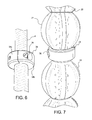
- bearing locks 34 may also be provided on the cable between a pair of sail bearings as shown in Fig. 1 .
- the bearing lock will be described in greater detail with reference to Figs. 6 and 7 .
- Each bearing lock 34 is formed of a rigid material such as metal.
- a lightweight aluminum material is preferred for the lock. It has an annular or donut configuration and includes a central through-opening.
- the lock is adjustable so that the diameter of the through-opening can be varied. The adjustment is provided by spreading apart two hinged portions 34a and 34b of the lock. This allows the lock to slide along the cable or cord when the lock is in the unlocked position.
- a locking screw 36 is arranged in aligned threaded openings in the hinged portions. As the screw is tightened, the lock is compressed against the cable so that it is secured in a locked position on the cable.
- Each lock on the cable will support the sail bearings above it, until another lock is reached.
- the locks thus relieve the pressure on the sail bearings below the lock by eliminating the weight of the bearings above the locks. This insures that the sail bearings remain free to rotate relative to the cable.
- the free rotation of the sail bearings facilitates smooth furling and unfurling of the sail while also protecting the sail cloth from abrasive contact with the cable.
- Many cables are made of a fibrous metal such as KEVLAR material. The cable has a rough surface which can snag the sail if the sail bearings are not provided. With the sail bearings on the furling assembly, the life of the sail is extended significantly.
- the sail bearings have a spherical configuration and multiple bearings are arranged on the cable.
- the bearing may have an elliptical configuration, with only a single bearing being arranged on the cable. If bearing locks are provided, elliptically shaped bearings can be arranged between the fitting and the lock and between the locks where more than one lock is provided. That is, there will be one more elliptical bearing provided on the cable than the number of bearing locks provided. This will insure that the bearings are freely rotatable on the cable for uniform furling and unfurling of the sail.
- the sail bearings are generally light weight. This makes it easy to disassemble the furling apparatus to stow the furled sail.
- the bottom fitting is disconnected from the swivel and can be inserted in a stowage bag.
- the line 8 can be released to gently lower the furled sail, with the sail being coiled in the bag. Once lowered, the line 8 is disconnected from the upper fitting 6 and the furled sail is stowed. The line can then be connected with the swivel until the sail is to be reconnected with the assembly for unfurling.
Landscapes
- Engineering & Computer Science (AREA)
- Life Sciences & Earth Sciences (AREA)
- Sustainable Development (AREA)
- Sustainable Energy (AREA)
- Chemical & Material Sciences (AREA)
- Combustion & Propulsion (AREA)
- Mechanical Engineering (AREA)
- Ocean & Marine Engineering (AREA)
- Rolling Contact Bearings (AREA)
- Finish Polishing, Edge Sharpening, And Grinding By Specific Grinding Devices (AREA)
Applications Claiming Priority (1)
| Application Number | Priority Date | Filing Date | Title |
|---|---|---|---|
| US13/600,783 US9027493B2 (en) | 2012-08-31 | 2012-08-31 | Sail bearing |
Publications (2)
| Publication Number | Publication Date |
|---|---|
| EP2703281A2 true EP2703281A2 (de) | 2014-03-05 |
| EP2703281A3 EP2703281A3 (de) | 2014-05-07 |
Family
ID=47294717
Family Applications (1)
| Application Number | Title | Priority Date | Filing Date |
|---|---|---|---|
| EP12195135.4A Withdrawn EP2703281A3 (de) | 2012-08-31 | 2012-11-30 | Segellager |
Country Status (2)
| Country | Link |
|---|---|
| US (2) | US9027493B2 (de) |
| EP (1) | EP2703281A3 (de) |
Families Citing this family (2)
| Publication number | Priority date | Publication date | Assignee | Title |
|---|---|---|---|---|
| US9027493B2 (en) * | 2012-08-31 | 2015-05-12 | Wichard Inc. | Sail bearing |
| ITPD20130111A1 (it) * | 2013-04-24 | 2014-10-25 | Armare Di Stefano Finco | Dispositivo avvolgitore per vele strallate e simili |
Citations (1)
| Publication number | Priority date | Publication date | Assignee | Title |
|---|---|---|---|---|
| US7975635B2 (en) | 2006-09-20 | 2011-07-12 | Renzo Greghi | Furling and unfurling device for asymmetric sails |
Family Cites Families (17)
| Publication number | Priority date | Publication date | Assignee | Title |
|---|---|---|---|---|
| GB485169A (en) | 1936-11-12 | 1938-05-12 | George Stanley Edlin | Improvements in cam mechanism |
| US3611969A (en) * | 1969-06-23 | 1971-10-12 | Frederick E Hood | Jib-furling stay |
| US3749042A (en) * | 1971-11-09 | 1973-07-31 | P Jackson | Furling and unfurling of sails |
| US3789790A (en) * | 1971-11-15 | 1974-02-05 | D Crall | System for reefing and furling sails |
| US3964419A (en) * | 1974-11-27 | 1976-06-22 | Uecker Ronald L | Anti-fouling roller furling gear upper assembly |
| US3958523A (en) * | 1975-05-30 | 1976-05-25 | Tracy Holmes Corporation | Sail hoisting, supporting and furling apparatus |
| US3980036A (en) * | 1976-03-08 | 1976-09-14 | Crall Donald H | Roller furling assembly |
| US4090461A (en) * | 1977-05-25 | 1978-05-23 | Anthony Rusich | Sail boat mast containing sail furling device with swivel haul-up means |
| US4122560A (en) | 1977-06-07 | 1978-10-31 | Baker William H | Quickly tensioned divider line for swimming pools |
| US4267790A (en) * | 1978-04-20 | 1981-05-19 | Hood Ralph S | Sail furling and reefing apparatus |
| FR2432432A1 (fr) * | 1978-08-04 | 1980-02-29 | Ingouf Pierre | Perfectionnement aux systemes enrouleurs de focs |
| US4723499A (en) * | 1985-08-19 | 1988-02-09 | Bernard Furgang | Furling system for sailboats |
| US5520562A (en) | 1994-12-22 | 1996-05-28 | Eddy; Roger C. | Wave suppressor |
| US5619946A (en) * | 1995-11-29 | 1997-04-15 | Wallasch; Lutz | Sail furling device with bearings to permit simultaneous cable and extrusion rotation |
| ITMI20040589A1 (it) | 2004-03-25 | 2004-06-25 | Renzo Greghi | Dispositivo di avvolgimento per vele |
| US8001916B2 (en) | 2009-05-07 | 2011-08-23 | Schaefer Marine, Inc. | Mega yacht mast tracking system with articulating sail feeder |
| US9027493B2 (en) * | 2012-08-31 | 2015-05-12 | Wichard Inc. | Sail bearing |
-
2012
- 2012-08-31 US US13/600,783 patent/US9027493B2/en not_active Expired - Fee Related
- 2012-11-30 EP EP12195135.4A patent/EP2703281A3/de not_active Withdrawn
-
2015
- 2015-01-16 US US14/598,674 patent/US20150128839A1/en not_active Abandoned
Patent Citations (1)
| Publication number | Priority date | Publication date | Assignee | Title |
|---|---|---|---|---|
| US7975635B2 (en) | 2006-09-20 | 2011-07-12 | Renzo Greghi | Furling and unfurling device for asymmetric sails |
Also Published As
| Publication number | Publication date |
|---|---|
| US20150128839A1 (en) | 2015-05-14 |
| EP2703281A3 (de) | 2014-05-07 |
| US9027493B2 (en) | 2015-05-12 |
| US20140060410A1 (en) | 2014-03-06 |
Similar Documents
| Publication | Publication Date | Title |
|---|---|---|
| US8708290B2 (en) | Line guide | |
| US4248281A (en) | Roll-reefing jib sail | |
| US9404256B2 (en) | Stowage and deployment of slit tube booms | |
| US9694890B2 (en) | Top down furling system | |
| US9027493B2 (en) | Sail bearing | |
| US3958523A (en) | Sail hoisting, supporting and furling apparatus | |
| US4723499A (en) | Furling system for sailboats | |
| EP3459901B1 (de) | Verschiebewerkzeug für verankerungsseil und verankerungswinde | |
| US20090084298A1 (en) | Mainsail reefing system | |
| US20150097148A1 (en) | Winch drum | |
| CN110844001A (zh) | 一种船舶用缆绳收卷装置 | |
| US8517345B2 (en) | Shipboard winch with guide vanes | |
| US5065686A (en) | Sail batten compression adjustment fitting | |
| US20140124719A1 (en) | Horizontal Drum Winch | |
| US4090461A (en) | Sail boat mast containing sail furling device with swivel haul-up means | |
| EP1188663B1 (de) | Rollreffsystem | |
| CN218055522U (zh) | 一种船用绳索锁具 | |
| CN207121289U (zh) | 配网实验收线器 | |
| EP2217521B1 (de) | Schiffswinde, schiff mit der schiffswinde | |
| US3800729A (en) | Jib downhaul | |
| US20210017769A1 (en) | Shading device having at least one awning | |
| US4646670A (en) | Sail system for sailboards, and boardsailing apparatus and method | |
| US9650116B2 (en) | Mounting system and associated apparatus | |
| US11161580B1 (en) | Roller assisted low friction reefing grommet | |
| CN223213570U (zh) | 一种便于收线的汽车线束 |
Legal Events
| Date | Code | Title | Description |
|---|---|---|---|
| AK | Designated contracting states |
Kind code of ref document: A2 Designated state(s): AL AT BE BG CH CY CZ DE DK EE ES FI FR GB GR HR HU IE IS IT LI LT LU LV MC MK MT NL NO PL PT RO RS SE SI SK SM TR |
|
| AX | Request for extension of the european patent |
Extension state: BA ME |
|
| PUAI | Public reference made under article 153(3) epc to a published international application that has entered the european phase |
Free format text: ORIGINAL CODE: 0009012 |
|
| PUAL | Search report despatched |
Free format text: ORIGINAL CODE: 0009013 |
|
| AK | Designated contracting states |
Kind code of ref document: A3 Designated state(s): AL AT BE BG CH CY CZ DE DK EE ES FI FR GB GR HR HU IE IS IT LI LT LU LV MC MK MT NL NO PL PT RO RS SE SI SK SM TR |
|
| AX | Request for extension of the european patent |
Extension state: BA ME |
|
| RIC1 | Information provided on ipc code assigned before grant |
Ipc: B63H 9/10 20060101AFI20140328BHEP Ipc: F16C 27/06 20060101ALI20140328BHEP |
|
| STAA | Information on the status of an ep patent application or granted ep patent |
Free format text: STATUS: THE APPLICATION IS DEEMED TO BE WITHDRAWN |
|
| 18D | Application deemed to be withdrawn |
Effective date: 20141108 |