EP2702309B1 - A tank for fluid - Google Patents
A tank for fluid Download PDFInfo
- Publication number
- EP2702309B1 EP2702309B1 EP12709076.9A EP12709076A EP2702309B1 EP 2702309 B1 EP2702309 B1 EP 2702309B1 EP 12709076 A EP12709076 A EP 12709076A EP 2702309 B1 EP2702309 B1 EP 2702309B1
- Authority
- EP
- European Patent Office
- Prior art keywords
- tank
- recess
- wall
- beam end
- accordance
- Prior art date
- Legal status (The legal status is an assumption and is not a legal conclusion. Google has not performed a legal analysis and makes no representation as to the accuracy of the status listed.)
- Not-in-force
Links
- 239000012530 fluid Substances 0.000 title claims description 6
- 238000010276 construction Methods 0.000 claims description 6
- 238000004873 anchoring Methods 0.000 claims description 4
- 239000003949 liquefied natural gas Substances 0.000 claims description 3
- 229930195733 hydrocarbon Natural products 0.000 claims description 2
- 150000002430 hydrocarbons Chemical class 0.000 claims description 2
- 238000003466 welding Methods 0.000 description 8
- 238000004519 manufacturing process Methods 0.000 description 3
- 238000000034 method Methods 0.000 description 3
- 238000003860 storage Methods 0.000 description 3
- 230000000694 effects Effects 0.000 description 2
- 238000005520 cutting process Methods 0.000 description 1
- 230000001419 dependent effect Effects 0.000 description 1
- 238000009826 distribution Methods 0.000 description 1
- 230000005484 gravity Effects 0.000 description 1
- 239000007788 liquid Substances 0.000 description 1
Images
Classifications
-
- F—MECHANICAL ENGINEERING; LIGHTING; HEATING; WEAPONS; BLASTING
- F17—STORING OR DISTRIBUTING GASES OR LIQUIDS
- F17C—VESSELS FOR CONTAINING OR STORING COMPRESSED, LIQUEFIED OR SOLIDIFIED GASES; FIXED-CAPACITY GAS-HOLDERS; FILLING VESSELS WITH, OR DISCHARGING FROM VESSELS, COMPRESSED, LIQUEFIED, OR SOLIDIFIED GASES
- F17C1/00—Pressure vessels, e.g. gas cylinder, gas tank, replaceable cartridge
- F17C1/02—Pressure vessels, e.g. gas cylinder, gas tank, replaceable cartridge involving reinforcing arrangements
- F17C1/08—Integral reinforcements, e.g. ribs
-
- F—MECHANICAL ENGINEERING; LIGHTING; HEATING; WEAPONS; BLASTING
- F17—STORING OR DISTRIBUTING GASES OR LIQUIDS
- F17C—VESSELS FOR CONTAINING OR STORING COMPRESSED, LIQUEFIED OR SOLIDIFIED GASES; FIXED-CAPACITY GAS-HOLDERS; FILLING VESSELS WITH, OR DISCHARGING FROM VESSELS, COMPRESSED, LIQUEFIED, OR SOLIDIFIED GASES
- F17C13/00—Details of vessels or of the filling or discharging of vessels
- F17C13/002—Details of vessels or of the filling or discharging of vessels for vessels under pressure
-
- F—MECHANICAL ENGINEERING; LIGHTING; HEATING; WEAPONS; BLASTING
- F17—STORING OR DISTRIBUTING GASES OR LIQUIDS
- F17C—VESSELS FOR CONTAINING OR STORING COMPRESSED, LIQUEFIED OR SOLIDIFIED GASES; FIXED-CAPACITY GAS-HOLDERS; FILLING VESSELS WITH, OR DISCHARGING FROM VESSELS, COMPRESSED, LIQUEFIED, OR SOLIDIFIED GASES
- F17C3/00—Vessels not under pressure
-
- F—MECHANICAL ENGINEERING; LIGHTING; HEATING; WEAPONS; BLASTING
- F17—STORING OR DISTRIBUTING GASES OR LIQUIDS
- F17C—VESSELS FOR CONTAINING OR STORING COMPRESSED, LIQUEFIED OR SOLIDIFIED GASES; FIXED-CAPACITY GAS-HOLDERS; FILLING VESSELS WITH, OR DISCHARGING FROM VESSELS, COMPRESSED, LIQUEFIED, OR SOLIDIFIED GASES
- F17C2201/00—Vessel construction, in particular geometry, arrangement or size
- F17C2201/01—Shape
- F17C2201/0104—Shape cylindrical
- F17C2201/0123—Shape cylindrical with variable thickness or diameter
-
- F—MECHANICAL ENGINEERING; LIGHTING; HEATING; WEAPONS; BLASTING
- F17—STORING OR DISTRIBUTING GASES OR LIQUIDS
- F17C—VESSELS FOR CONTAINING OR STORING COMPRESSED, LIQUEFIED OR SOLIDIFIED GASES; FIXED-CAPACITY GAS-HOLDERS; FILLING VESSELS WITH, OR DISCHARGING FROM VESSELS, COMPRESSED, LIQUEFIED, OR SOLIDIFIED GASES
- F17C2201/00—Vessel construction, in particular geometry, arrangement or size
- F17C2201/01—Shape
- F17C2201/0128—Shape spherical or elliptical
-
- F—MECHANICAL ENGINEERING; LIGHTING; HEATING; WEAPONS; BLASTING
- F17—STORING OR DISTRIBUTING GASES OR LIQUIDS
- F17C—VESSELS FOR CONTAINING OR STORING COMPRESSED, LIQUEFIED OR SOLIDIFIED GASES; FIXED-CAPACITY GAS-HOLDERS; FILLING VESSELS WITH, OR DISCHARGING FROM VESSELS, COMPRESSED, LIQUEFIED, OR SOLIDIFIED GASES
- F17C2201/00—Vessel construction, in particular geometry, arrangement or size
- F17C2201/01—Shape
- F17C2201/0147—Shape complex
- F17C2201/0157—Polygonal
-
- F—MECHANICAL ENGINEERING; LIGHTING; HEATING; WEAPONS; BLASTING
- F17—STORING OR DISTRIBUTING GASES OR LIQUIDS
- F17C—VESSELS FOR CONTAINING OR STORING COMPRESSED, LIQUEFIED OR SOLIDIFIED GASES; FIXED-CAPACITY GAS-HOLDERS; FILLING VESSELS WITH, OR DISCHARGING FROM VESSELS, COMPRESSED, LIQUEFIED, OR SOLIDIFIED GASES
- F17C2201/00—Vessel construction, in particular geometry, arrangement or size
- F17C2201/05—Size
- F17C2201/052—Size large (>1000 m3)
-
- F—MECHANICAL ENGINEERING; LIGHTING; HEATING; WEAPONS; BLASTING
- F17—STORING OR DISTRIBUTING GASES OR LIQUIDS
- F17C—VESSELS FOR CONTAINING OR STORING COMPRESSED, LIQUEFIED OR SOLIDIFIED GASES; FIXED-CAPACITY GAS-HOLDERS; FILLING VESSELS WITH, OR DISCHARGING FROM VESSELS, COMPRESSED, LIQUEFIED, OR SOLIDIFIED GASES
- F17C2203/00—Vessel construction, in particular walls or details thereof
- F17C2203/01—Reinforcing or suspension means
- F17C2203/011—Reinforcing means
- F17C2203/012—Reinforcing means on or in the wall, e.g. ribs
-
- F—MECHANICAL ENGINEERING; LIGHTING; HEATING; WEAPONS; BLASTING
- F17—STORING OR DISTRIBUTING GASES OR LIQUIDS
- F17C—VESSELS FOR CONTAINING OR STORING COMPRESSED, LIQUEFIED OR SOLIDIFIED GASES; FIXED-CAPACITY GAS-HOLDERS; FILLING VESSELS WITH, OR DISCHARGING FROM VESSELS, COMPRESSED, LIQUEFIED, OR SOLIDIFIED GASES
- F17C2203/00—Vessel construction, in particular walls or details thereof
- F17C2203/01—Reinforcing or suspension means
- F17C2203/011—Reinforcing means
- F17C2203/013—Reinforcing means in the vessel, e.g. columns
-
- F—MECHANICAL ENGINEERING; LIGHTING; HEATING; WEAPONS; BLASTING
- F17—STORING OR DISTRIBUTING GASES OR LIQUIDS
- F17C—VESSELS FOR CONTAINING OR STORING COMPRESSED, LIQUEFIED OR SOLIDIFIED GASES; FIXED-CAPACITY GAS-HOLDERS; FILLING VESSELS WITH, OR DISCHARGING FROM VESSELS, COMPRESSED, LIQUEFIED, OR SOLIDIFIED GASES
- F17C2203/00—Vessel construction, in particular walls or details thereof
- F17C2203/06—Materials for walls or layers thereof; Properties or structures of walls or their materials
- F17C2203/0634—Materials for walls or layers thereof
- F17C2203/0636—Metals
-
- F—MECHANICAL ENGINEERING; LIGHTING; HEATING; WEAPONS; BLASTING
- F17—STORING OR DISTRIBUTING GASES OR LIQUIDS
- F17C—VESSELS FOR CONTAINING OR STORING COMPRESSED, LIQUEFIED OR SOLIDIFIED GASES; FIXED-CAPACITY GAS-HOLDERS; FILLING VESSELS WITH, OR DISCHARGING FROM VESSELS, COMPRESSED, LIQUEFIED, OR SOLIDIFIED GASES
- F17C2209/00—Vessel construction, in particular methods of manufacturing
- F17C2209/22—Assembling processes
- F17C2209/221—Welding
-
- F—MECHANICAL ENGINEERING; LIGHTING; HEATING; WEAPONS; BLASTING
- F17—STORING OR DISTRIBUTING GASES OR LIQUIDS
- F17C—VESSELS FOR CONTAINING OR STORING COMPRESSED, LIQUEFIED OR SOLIDIFIED GASES; FIXED-CAPACITY GAS-HOLDERS; FILLING VESSELS WITH, OR DISCHARGING FROM VESSELS, COMPRESSED, LIQUEFIED, OR SOLIDIFIED GASES
- F17C2209/00—Vessel construction, in particular methods of manufacturing
- F17C2209/23—Manufacturing of particular parts or at special locations
- F17C2209/232—Manufacturing of particular parts or at special locations of walls
-
- F—MECHANICAL ENGINEERING; LIGHTING; HEATING; WEAPONS; BLASTING
- F17—STORING OR DISTRIBUTING GASES OR LIQUIDS
- F17C—VESSELS FOR CONTAINING OR STORING COMPRESSED, LIQUEFIED OR SOLIDIFIED GASES; FIXED-CAPACITY GAS-HOLDERS; FILLING VESSELS WITH, OR DISCHARGING FROM VESSELS, COMPRESSED, LIQUEFIED, OR SOLIDIFIED GASES
- F17C2221/00—Handled fluid, in particular type of fluid
- F17C2221/03—Mixtures
- F17C2221/032—Hydrocarbons
- F17C2221/033—Methane, e.g. natural gas, CNG, LNG, GNL, GNC, PLNG
-
- F—MECHANICAL ENGINEERING; LIGHTING; HEATING; WEAPONS; BLASTING
- F17—STORING OR DISTRIBUTING GASES OR LIQUIDS
- F17C—VESSELS FOR CONTAINING OR STORING COMPRESSED, LIQUEFIED OR SOLIDIFIED GASES; FIXED-CAPACITY GAS-HOLDERS; FILLING VESSELS WITH, OR DISCHARGING FROM VESSELS, COMPRESSED, LIQUEFIED, OR SOLIDIFIED GASES
- F17C2223/00—Handled fluid before transfer, i.e. state of fluid when stored in the vessel or before transfer from the vessel
- F17C2223/01—Handled fluid before transfer, i.e. state of fluid when stored in the vessel or before transfer from the vessel characterised by the phase
- F17C2223/0146—Two-phase
- F17C2223/0153—Liquefied gas, e.g. LPG, GPL
- F17C2223/0161—Liquefied gas, e.g. LPG, GPL cryogenic, e.g. LNG, GNL, PLNG
-
- F—MECHANICAL ENGINEERING; LIGHTING; HEATING; WEAPONS; BLASTING
- F17—STORING OR DISTRIBUTING GASES OR LIQUIDS
- F17C—VESSELS FOR CONTAINING OR STORING COMPRESSED, LIQUEFIED OR SOLIDIFIED GASES; FIXED-CAPACITY GAS-HOLDERS; FILLING VESSELS WITH, OR DISCHARGING FROM VESSELS, COMPRESSED, LIQUEFIED, OR SOLIDIFIED GASES
- F17C2223/00—Handled fluid before transfer, i.e. state of fluid when stored in the vessel or before transfer from the vessel
- F17C2223/03—Handled fluid before transfer, i.e. state of fluid when stored in the vessel or before transfer from the vessel characterised by the pressure level
- F17C2223/033—Small pressure, e.g. for liquefied gas
-
- F—MECHANICAL ENGINEERING; LIGHTING; HEATING; WEAPONS; BLASTING
- F17—STORING OR DISTRIBUTING GASES OR LIQUIDS
- F17C—VESSELS FOR CONTAINING OR STORING COMPRESSED, LIQUEFIED OR SOLIDIFIED GASES; FIXED-CAPACITY GAS-HOLDERS; FILLING VESSELS WITH, OR DISCHARGING FROM VESSELS, COMPRESSED, LIQUEFIED, OR SOLIDIFIED GASES
- F17C2260/00—Purposes of gas storage and gas handling
- F17C2260/01—Improving mechanical properties or manufacturing
- F17C2260/011—Improving strength
-
- F—MECHANICAL ENGINEERING; LIGHTING; HEATING; WEAPONS; BLASTING
- F17—STORING OR DISTRIBUTING GASES OR LIQUIDS
- F17C—VESSELS FOR CONTAINING OR STORING COMPRESSED, LIQUEFIED OR SOLIDIFIED GASES; FIXED-CAPACITY GAS-HOLDERS; FILLING VESSELS WITH, OR DISCHARGING FROM VESSELS, COMPRESSED, LIQUEFIED, OR SOLIDIFIED GASES
- F17C2260/00—Purposes of gas storage and gas handling
- F17C2260/01—Improving mechanical properties or manufacturing
- F17C2260/013—Reducing manufacturing time or effort
-
- F—MECHANICAL ENGINEERING; LIGHTING; HEATING; WEAPONS; BLASTING
- F17—STORING OR DISTRIBUTING GASES OR LIQUIDS
- F17C—VESSELS FOR CONTAINING OR STORING COMPRESSED, LIQUEFIED OR SOLIDIFIED GASES; FIXED-CAPACITY GAS-HOLDERS; FILLING VESSELS WITH, OR DISCHARGING FROM VESSELS, COMPRESSED, LIQUEFIED, OR SOLIDIFIED GASES
- F17C2260/00—Purposes of gas storage and gas handling
- F17C2260/01—Improving mechanical properties or manufacturing
- F17C2260/016—Preventing slosh
-
- F—MECHANICAL ENGINEERING; LIGHTING; HEATING; WEAPONS; BLASTING
- F17—STORING OR DISTRIBUTING GASES OR LIQUIDS
- F17C—VESSELS FOR CONTAINING OR STORING COMPRESSED, LIQUEFIED OR SOLIDIFIED GASES; FIXED-CAPACITY GAS-HOLDERS; FILLING VESSELS WITH, OR DISCHARGING FROM VESSELS, COMPRESSED, LIQUEFIED, OR SOLIDIFIED GASES
- F17C2270/00—Applications
- F17C2270/01—Applications for fluid transport or storage
- F17C2270/0102—Applications for fluid transport or storage on or in the water
- F17C2270/0105—Ships
-
- F—MECHANICAL ENGINEERING; LIGHTING; HEATING; WEAPONS; BLASTING
- F17—STORING OR DISTRIBUTING GASES OR LIQUIDS
- F17C—VESSELS FOR CONTAINING OR STORING COMPRESSED, LIQUEFIED OR SOLIDIFIED GASES; FIXED-CAPACITY GAS-HOLDERS; FILLING VESSELS WITH, OR DISCHARGING FROM VESSELS, COMPRESSED, LIQUEFIED, OR SOLIDIFIED GASES
- F17C2270/00—Applications
- F17C2270/01—Applications for fluid transport or storage
- F17C2270/0102—Applications for fluid transport or storage on or in the water
- F17C2270/011—Barges
- F17C2270/0113—Barges floating
-
- F—MECHANICAL ENGINEERING; LIGHTING; HEATING; WEAPONS; BLASTING
- F17—STORING OR DISTRIBUTING GASES OR LIQUIDS
- F17C—VESSELS FOR CONTAINING OR STORING COMPRESSED, LIQUEFIED OR SOLIDIFIED GASES; FIXED-CAPACITY GAS-HOLDERS; FILLING VESSELS WITH, OR DISCHARGING FROM VESSELS, COMPRESSED, LIQUEFIED, OR SOLIDIFIED GASES
- F17C2270/00—Applications
- F17C2270/01—Applications for fluid transport or storage
- F17C2270/0102—Applications for fluid transport or storage on or in the water
- F17C2270/0118—Offshore
- F17C2270/0123—Terminals
-
- F—MECHANICAL ENGINEERING; LIGHTING; HEATING; WEAPONS; BLASTING
- F17—STORING OR DISTRIBUTING GASES OR LIQUIDS
- F17C—VESSELS FOR CONTAINING OR STORING COMPRESSED, LIQUEFIED OR SOLIDIFIED GASES; FIXED-CAPACITY GAS-HOLDERS; FILLING VESSELS WITH, OR DISCHARGING FROM VESSELS, COMPRESSED, LIQUEFIED, OR SOLIDIFIED GASES
- F17C2270/00—Applications
- F17C2270/01—Applications for fluid transport or storage
- F17C2270/0134—Applications for fluid transport or storage placed above the ground
- F17C2270/0136—Terminals
Definitions
- the present invention concerns a tank for fluid, especially hydrocarbons including low temperature liquefied natural gas, as defined in the preamble of the independent claim 1.
- the tank may be used for storage, distribution and transportation of fluid.
- the tanks may be used for various purposes onboard ships and floating vessels, such as storage and fuelling. Further the tanks may be employed on gravity based offshore structures and land tanks exposed to dynamic loads such as wave loads and loads caused by earth quake.
- the tank in accordance with the invention may also be applied as a pressure tank, which should be designed to endure the exposure to high internal pressure.
- the inventive tank comprises tank walls defining an interior tank space.
- the tank may be provided having different configurations such as for instance spherical, cylindric, conical and various prismatic shapes.
- a double wall tank construction is the most common design structure for storage of low temperature liquefied natural gas under pressure, but it may also be used for pressure vessels in general, and this tank may also be the choice for the tank according to the invention.
- the tank wall has a sandwich structure, whereby extruded beam elements are assembled to a sandwich structure.
- a beam arrangement is positioned in the interior of the tank.
- the beam arrangement comprises several beams, preferably tension stays, organized orthogonal relative to each other such as in layers.
- the beam arrangement in addition reduces the sloshing effect caused by the motion of the ship and the motion of the liquid itself.
- the beams each have at least one end connected to the tank wall.
- the beams may form interconnection points with other beams or each of the beam ends may be connected to a separate tank wall. It has proven advantageous to arrange the beams in the interior tank space in an orthogonal three dimensional pattern.
- the beams, or tensions stays may be extruded or produced from rolled profiles or by any other producing method to produce a beam giving sufficient strength to the tank construction.
- US2007194051 discloses a tank for fluid wherein the tank comprises walls defining an interior tank space and at least one beam is provided in the interior space having at least one beam end connected to the tank wall, by means of a flange connected to the beam by means of welding.
- At least one beam is provided in the interior tank space having at least one beam end connected to the tank wall.
- the beam end(s) includes a bracket for attachment to the tank wall.
- the bracket may be connected to the beam end by welding, using bolting or by other suitable means.
- the bracket will be forming the attachment of the beam end to the tank wall, and the bracket is arranged to be received and anchored in the recess in the tank wall.
- At least one recess is provided in the tank wall for receiving the beam end for anchoring to the tank wall.
- the mouth of the recess opening into the interior tank space has a size to allow for parts of the beam end or the bracket to extend through it, with the end parts of the beam end or the bracket to be received and anchored in the recess.
- the recesses are configured so that when positioning the beam end, with or without the bracket into the recess provided in the tank wall, the configuration of the recess, wherein the mouth of the recess is smaller than the profile of the beam end/bracket, provide an anchorage for the beam end locking the beam in place relative to the tank wall.
- the recess may then be profiled corresponding to the profile of the beam end (or bracket) in accordance with this embodiment.
- the beam end When anchoring the beam to the tank wall, the beam end enters an end portion of the recess and is positioned in the recess at the desired location.
- the beam is anchored to the tank wall due to the size of the mouth being smaller than the end portion of the beam end/bracket.
- a portion of the beam end (or bracket) extends out through the mouth of the recess opening into the interior of the tank.
- the mouth of the recess facing the interior space of the tank is dimensioned with a size enabling the beam end/bracket to be inserted into the recess from the interior of the tank.
- locking means are provided.
- the locking means may comprise wedge elements to be positioned into the recess by entering through the end portion of the recess or alternatively through the mouth of the recess opening into the tank interior space.
- the wedging elements have a portion which is larger than the size of the mouth of the recess, thereby providing a wedging effect to the beam end/bracket to anchor the beam to the tank wall.
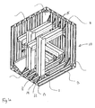
- FIG. 10 An embodiment of the tank 10 is shown in fig 1a .
- the tank is shown having a double wall construction made up by interconnected extruded beam elements 3.
- the beam elements 3 provide an inner wall 11 and an outer wall 12, and internal wall sections running in between the outer and the inner wall 11, 12.
- the innerwall sections 13 have an inclined connection to the inner and outer wall 11, 12.
- the inner wall sections 14 are perpendicularly connected to the inner and outer wall 11, 12.
- the profile/the cross section of this sandwich construction making up the tank walls may have an outlay different from the one showed in the figure.
- the inner wall sections may be positioned in various ways providing various profile patterns in accordance with the design criteria of the specific tank.
- the tank wall may be constituted by beam elements having different or similar profile pattern so that the profile may be uniform or non uniform along the wall.
- the double wall construction may of course be provided otherwise than by using interconnected extruded beam elements 3.
- the tank 10 is provided with beams 1 having an H profile, arranged in the interior space of the tank to strengthen the tank structure to resist load impact working on the structure of the tank.
- the beams 1 are shown arranged vertically and horizontally in an orthogonal pattern as tension stays. As shown in fig 1 one end of the beam is connected to the tank wall and the other beam end is connected in a perpendicular manner to another beam end.
- a bracket 2 is connected to one end of the beam 1 to be anchored to the wall.
- the bracket 2 is shown connected to the beam end by the use of bolts 4, and the beam ends are connected using welding. However, as the skilled person will realize these connections may be provided otherwise, for instance by welding the beam end to the bracket or using bolts connecting the beam ends.
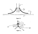
- Figs 1b and 1c show the beam 1 with a bracket 2 having a profile fitting into a recess 20 arranged in the tank wall.
- the bracket 2 needs to be fitted into the recess 20 with the bracket 2 entering an end portion of the recess as the mouth 21 is too small for the bracket to enter the recess from the interior space of the tank.
- the small mouth 21 of the recess opening into the interior space of the tank makes sure that the bracket is anchored securely in the tank wall after being installed through the end portion of the recess 20.
- the recess 20 may run along a portion of the wall or along the entire length of the wall, wherein the end portion of the recess correspond with the end surface 15 of the tank wall.
- the recess may be made as part of the profile when manufacturing the wall or may be provided as needed after the tank has been completed.
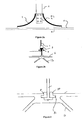
- FIG. 2a, 2b, 3 an embodiment of the invention including an alternative anchorage of the beam to the wall, is shown.
- the mouth 21 of the recess 20 opens into the interior of the tank, and the size of the profile fits into the mouth 21, thereby enabling the bracket to enter the recess from the interior of the tank.
- Locking means here shown as L-shaped locking wedges 30, are provided to make sure the beam end has anchorage to the tank wall.
- the locking wedges 30 as shown in fig 3 enter the end portion of the recess and are secured in the recess due to the difference between the size of the mouth 21 and locking parts 31 of the locking wedges.
- the locking means may comprise one or more elements, and the locking wedges may be provided to enter the recess through the mouth 21, wherein the locking wedges in this case have a configuration different from that shown in fig 3 .
Landscapes
- Engineering & Computer Science (AREA)
- Mechanical Engineering (AREA)
- General Engineering & Computer Science (AREA)
- Filling Or Discharging Of Gas Storage Vessels (AREA)
Description
- The present invention concerns a tank for fluid, especially hydrocarbons including low temperature liquefied natural gas, as defined in the preamble of the
independent claim 1. The tank may be used for storage, distribution and transportation of fluid. The tanks may used for various purposes onboard ships and floating vessels, such as storage and fuelling. Further the tanks may be employed on gravity based offshore structures and land tanks exposed to dynamic loads such as wave loads and loads caused by earth quake. The tank in accordance with the invention may also be applied as a pressure tank, which should be designed to endure the exposure to high internal pressure. - The inventive tank comprises tank walls defining an interior tank space. The tank may be provided having different configurations such as for instance spherical, cylindric, conical and various prismatic shapes. A double wall tank construction is the most common design structure for storage of low temperature liquefied natural gas under pressure, but it may also be used for pressure vessels in general, and this tank may also be the choice for the tank according to the invention. In one aspect the tank wall has a sandwich structure, whereby extruded beam elements are assembled to a sandwich structure.
- In order to provide sufficient strength to the tank structure a beam arrangement is positioned in the interior of the tank. The beam arrangement comprises several beams, preferably tension stays, organized orthogonal relative to each other such as in layers. When portions of the fluid have a liquefied state, the beam arrangement in addition reduces the sloshing effect caused by the motion of the ship and the motion of the liquid itself.
- The beams each have at least one end connected to the tank wall. The beams may form interconnection points with other beams or each of the beam ends may be connected to a separate tank wall. It has proven advantageous to arrange the beams in the interior tank space in an orthogonal three dimensional pattern.
- The beams, or tensions stays, may be extruded or produced from rolled profiles or by any other producing method to produce a beam giving sufficient strength to the tank construction.
- Traditionally the tension stays/beams have been welded to the tank walls using friction welding or MIG welding. Welding procedures are time and cost consuming, and a need for solutions providing an alternative to the welding procedure would prove valuable in cutting production cost for manufacturing of the tank.
-
US2007194051 discloses a tank for fluid wherein the tank comprises walls defining an interior tank space and at least one beam is provided in the interior space having at least one beam end connected to the tank wall, by means of a flange connected to the beam by means of welding. - Prior art documents also include
DE 19934620 andUS 4225054 . - It is an object of the invention to provide an alternative solution for a robust and reliable connection between the beam and the tank wall. In accordance with a tank as defined in the independent claim a mechanical connection is proposed for attaching the beam to the tank wall. Further embodiments of the invention are defined in the following dependent claims.
- In accordance with the tank as defined in the independent claim, at least one beam is provided in the interior tank space having at least one beam end connected to the tank wall.
- In one embodiment of the invention the beam end(s) includes a bracket for attachment to the tank wall. The bracket may be connected to the beam end by welding, using bolting or by other suitable means. In this embodiment the bracket will be forming the attachment of the beam end to the tank wall, and the bracket is arranged to be received and anchored in the recess in the tank wall.
- At least one recess is provided in the tank wall for receiving the beam end for anchoring to the tank wall. The mouth of the recess opening into the interior tank space has a size to allow for parts of the beam end or the bracket to extend through it, with the end parts of the beam end or the bracket to be received and anchored in the recess.
- In one embodiment the recesses are configured so that when positioning the beam end, with or without the bracket into the recess provided in the tank wall, the configuration of the recess, wherein the mouth of the recess is smaller than the profile of the beam end/bracket, provide an anchorage for the beam end locking the beam in place relative to the tank wall. The recess may then be profiled corresponding to the profile of the beam end (or bracket) in accordance with this embodiment. When anchoring the beam to the tank wall, the beam end enters an end portion of the recess and is positioned in the recess at the desired location. The beam is anchored to the tank wall due to the size of the mouth being smaller than the end portion of the beam end/bracket. When the beam end/bracket is installed for anchorage in the recess a portion of the beam end (or bracket) extends out through the mouth of the recess opening into the interior of the tank.
- In another embodiment in accordance with the invention the mouth of the recess facing the interior space of the tank, is dimensioned with a size enabling the beam end/bracket to be inserted into the recess from the interior of the tank. To provide anchorage for the beam end to the tank wall, locking means are provided. The locking means may comprise wedge elements to be positioned into the recess by entering through the end portion of the recess or alternatively through the mouth of the recess opening into the tank interior space. The wedging elements have a portion which is larger than the size of the mouth of the recess, thereby providing a wedging effect to the beam end/bracket to anchor the beam to the tank wall.
- An example of an embodiment of the invention will be described with reference to the figs where
-
Fig 1a shows a perspective view of the tank structure. -
Fig 1b shows the connection of the beam end to the wall in accordance with one embodiment of the invention. -
Fig 1c is a section through the bracket and tank wall as indicated by arrows infig 1b . -
Fig 2a shows the connection of the beam end to the wall in accordance with another embodiment of the invention. -
Fig 2b shows a section through the bracket and tank wall as indicated by arrows infig 2a . -
Fig 3 shows a section through the bracket and tank wall showing the anchorage of the beam end to the wall in detail. - An embodiment of the
tank 10 is shown infig 1a . The tank is shown having a double wall construction made up by interconnected extruded beam elements 3. The beam elements 3 provide an inner wall 11 and anouter wall 12, and internal wall sections running in between the outer and theinner wall 11, 12. Theinnerwall sections 13 have an inclined connection to the inner andouter wall 11, 12. And the inner wall sections 14 are perpendicularly connected to the inner andouter wall 11, 12. - As the skilled person will understand, the profile/the cross section of this sandwich construction making up the tank walls may have an outlay different from the one showed in the figure. The inner wall sections may be positioned in various ways providing various profile patterns in accordance with the design criteria of the specific tank. Further, the tank wall may be constituted by beam elements having different or similar profile pattern so that the profile may be uniform or non uniform along the wall. The double wall construction may of course be provided otherwise than by using interconnected extruded beam elements 3.
- The
tank 10 is provided withbeams 1 having an H profile, arranged in the interior space of the tank to strengthen the tank structure to resist load impact working on the structure of the tank. Thebeams 1 are shown arranged vertically and horizontally in an orthogonal pattern as tension stays. As shown infig 1 one end of the beam is connected to the tank wall and the other beam end is connected in a perpendicular manner to another beam end. Abracket 2 is connected to one end of thebeam 1 to be anchored to the wall. Thebracket 2 is shown connected to the beam end by the use ofbolts 4, and the beam ends are connected using welding. However, as the skilled person will realize these connections may be provided otherwise, for instance by welding the beam end to the bracket or using bolts connecting the beam ends. -
Figs 1b and 1c show thebeam 1 with abracket 2 having a profile fitting into arecess 20 arranged in the tank wall. In the embodiment shown infigs 1b and 1c thebracket 2 needs to be fitted into therecess 20 with thebracket 2 entering an end portion of the recess as themouth 21 is too small for the bracket to enter the recess from the interior space of the tank. Thesmall mouth 21 of the recess opening into the interior space of the tank makes sure that the bracket is anchored securely in the tank wall after being installed through the end portion of therecess 20. Therecess 20 may run along a portion of the wall or along the entire length of the wall, wherein the end portion of the recess correspond with the end surface 15 of the tank wall. The recess may be made as part of the profile when manufacturing the wall or may be provided as needed after the tank has been completed. - In
figs 2a, 2b, 3 an embodiment of the invention including an alternative anchorage of the beam to the wall, is shown. Themouth 21 of therecess 20 opens into the interior of the tank, and the size of the profile fits into themouth 21, thereby enabling the bracket to enter the recess from the interior of the tank. Thus in accordance with this embodiment there is no need for the bracket to enter the recess through its end portion as in the embodiment shown infig 1b, 1c . Locking means, here shown as L-shapedlocking wedges 30, are provided to make sure the beam end has anchorage to the tank wall. The lockingwedges 30 as shown infig 3 enter the end portion of the recess and are secured in the recess due to the difference between the size of themouth 21 and lockingparts 31 of the locking wedges. As the skilled person may realize the locking means may comprise one or more elements, and the locking wedges may be provided to enter the recess through themouth 21, wherein the locking wedges in this case have a configuration different from that shown infig 3 . - The anchorage of the beam end to the wall has herein been described having a bracket fitted to the beam end, as the skilled person will realize, these descriptions will also apply to the aspect of the invention where the beam end is not provided with a bracket, but where the beam end is arranged to be anchored directly to the tank wall.
Claims (10)
- A tank (10) for fluid, especially hydrocarbons including low temperature liquefied natural gas, wherein the tank (10) comprises tank walls defining an interior tank space, wherein at least one beam (1) is provided in the interior tank space having at least one beam end connected to the tank wall,
characterized in that at least one recess (20) is provided in the tank wall for receiving the beam end for anchoring to the tank wall. - A tank in accordance with claim 1,
characterized in that the at least one recess (20) has a configuration providing anchorage for the beam end. - A tank in accordance with claim 1 or 2,
characterized in that the recess (20) has a mouth (21) in the tank wall facing the interior space of the tank, wherein the profile of the beam end to be received in the recess (20) fits into the size of mouth (21). - A tank in accordance with one of the claims 1-3,
characterized in that locking means are provided for anchoring the beam end to the tank wall. - A tank in accordance with one of the claims 4,
characterized in that the locking means are constituted by at least one wedge element to be inserted into the recess (20) securing the beam end to the tank wall. - A tank in accordance with claim 4 or 5,
characterized in that the locking means is provided to be inserted through the mouth (21) or an end portion of the recess (20). - A tank in accordance with one of the claims 1 or 2,
characterized in that the recess (20) has a profile corresponding essentially to the profile of the beam end and the mouth (21) of the recess (20) is sized smaller than the end portion of the beam end, wherein the beam end is to enter the recess (20) through an open end portion of the recess (20). - A tank in accordance with one of the claims 1-7,
characterized in that the tank walls have a double wall construction providing the tank wall with an inner (11) and outer wall (12). - A tank in accordance with one of the claims 1-8,
characterized in that the at least one beam end includes a bracket (2) to be received and anchored in the recess (20) in the tank wall. - A tank in accordance with one of the claims 1-9,
characterized in that the beams (1) are arranged in the interior tank space in an orthogonal three dimensional pattern.
Applications Claiming Priority (2)
| Application Number | Priority Date | Filing Date | Title |
|---|---|---|---|
| NO20110643A NO333035B1 (en) | 2011-04-29 | 2011-04-29 | A tank for fluid |
| PCT/EP2012/054311 WO2012146435A1 (en) | 2011-04-29 | 2012-03-13 | A tank for fluid |
Publications (2)
| Publication Number | Publication Date |
|---|---|
| EP2702309A1 EP2702309A1 (en) | 2014-03-05 |
| EP2702309B1 true EP2702309B1 (en) | 2015-03-04 |
Family
ID=45841479
Family Applications (1)
| Application Number | Title | Priority Date | Filing Date |
|---|---|---|---|
| EP12709076.9A Not-in-force EP2702309B1 (en) | 2011-04-29 | 2012-03-13 | A tank for fluid |
Country Status (7)
| Country | Link |
|---|---|
| US (1) | US8985381B2 (en) |
| EP (1) | EP2702309B1 (en) |
| JP (1) | JP2014513016A (en) |
| KR (1) | KR20140031276A (en) |
| CN (1) | CN103688099A (en) |
| NO (1) | NO333035B1 (en) |
| WO (1) | WO2012146435A1 (en) |
Families Citing this family (1)
| Publication number | Priority date | Publication date | Assignee | Title |
|---|---|---|---|---|
| SI24001A (en) * | 2012-02-10 | 2013-08-30 | Aerogel Card D.O.O. | Cryogenic device for transport and storage of liquefaction gas |
Family Cites Families (9)
| Publication number | Priority date | Publication date | Assignee | Title |
|---|---|---|---|---|
| FR2398961A1 (en) | 1977-07-26 | 1979-02-23 | Gaz Transport | THERMALLY INSULATED TANK FOR THE GROUND STORAGE OF LOW TEMPERATURE LIQUID, IN PARTICULAR LIQUEFIED NATURAL GAS |
| JPH0714753B2 (en) * | 1988-10-03 | 1995-02-22 | 積水化学工業株式会社 | Beam for panel tank |
| CA2264921C (en) * | 1996-09-03 | 2009-07-14 | Cordant Technologies Inc. | Improved joint for connecting extrudable segments |
| FR2781557B1 (en) * | 1998-07-24 | 2000-09-15 | Gaz Transport & Technigaz | IMPROVEMENT FOR A WATERPROOF AND THERMALLY INSULATING TANK WITH PREFABRICATED PANELS |
| FI20040382L (en) | 2004-03-10 | 2005-09-11 | Aker Finnyards Oy | Method for designing and manufacturing an LNG storage tank or the like and an aluminum LNG storage tank manufactured by the method |
| NO20042702D0 (en) * | 2004-06-25 | 2004-06-25 | Det Norske Veritas As | Cellular tanks for storage of fluids at tow temperatures, and cell structure for use in a tank |
| US20070194051A1 (en) * | 2004-06-25 | 2007-08-23 | Kare Bakken | Cellular tanks for storage of fluid at low temperatures |
| CN2827952Y (en) * | 2005-10-26 | 2006-10-18 | 金继华 | Container type mobile fuelling station tank |
| NO330085B1 (en) * | 2007-02-20 | 2011-02-14 | Aker Engineering & Technology | A tank structure for storing and transporting fluids |
-
2011
- 2011-04-29 NO NO20110643A patent/NO333035B1/en not_active IP Right Cessation
-
2012
- 2012-03-13 WO PCT/EP2012/054311 patent/WO2012146435A1/en not_active Ceased
- 2012-03-13 CN CN201280019969.2A patent/CN103688099A/en active Pending
- 2012-03-13 EP EP12709076.9A patent/EP2702309B1/en not_active Not-in-force
- 2012-03-13 KR KR1020137031583A patent/KR20140031276A/en not_active Withdrawn
- 2012-03-13 US US14/111,768 patent/US8985381B2/en not_active Expired - Fee Related
- 2012-03-13 JP JP2014506804A patent/JP2014513016A/en active Pending
Also Published As
| Publication number | Publication date |
|---|---|
| NO333035B1 (en) | 2013-02-18 |
| WO2012146435A1 (en) | 2012-11-01 |
| CN103688099A (en) | 2014-03-26 |
| US8985381B2 (en) | 2015-03-24 |
| EP2702309A1 (en) | 2014-03-05 |
| JP2014513016A (en) | 2014-05-29 |
| NO20110643A1 (en) | 2012-10-30 |
| KR20140031276A (en) | 2014-03-12 |
| US20140166663A1 (en) | 2014-06-19 |
Similar Documents
| Publication | Publication Date | Title |
|---|---|---|
| EP3342699B1 (en) | Floating offshore platform | |
| KR101865512B1 (en) | Construction method of one body type jacket support structure for offshore wind turbine | |
| US20190367136A1 (en) | Floating device supporting an offshore wind turbine, and corresponding floating wind turbine unit | |
| EP2836708B1 (en) | Floating wind turbine platform and method of assembling | |
| EP2126454B1 (en) | A tank structure | |
| WO2013015296A1 (en) | Lng tank loaded on board lng ship, and method for producing same | |
| US20230331358A1 (en) | Floating platform for supporting offshore power generation structures and method for making said platform | |
| US8985381B2 (en) | Tank for fluid | |
| KR101009815B1 (en) | Insulation panel assembly for liquefied gas storage tank and installation method using the same | |
| US11053703B2 (en) | Support structure for a wind turbine | |
| JP5809036B2 (en) | Tank structure and ship | |
| KR20200004297A (en) | Semi-submersible float, especially for wind turbines | |
| JP5007367B1 (en) | PC ground tank and its construction method | |
| JP7088452B2 (en) | Offshore floating structure | |
| CA2857910A1 (en) | Cellular tendons for tlp | |
| KR20130121529A (en) | Block type jacket structure | |
| KR101613844B1 (en) | Transition pieces of offshore wind turbines and whole structure of wind turbines having it | |
| RU2857234C1 (en) | Method for connecting pontoons made of polymer composite materials | |
| KR20250121362A (en) | Method for manufacturing a floating body, especially a floating body of a floating structure of an offshore wind turbine | |
| RU2790907C1 (en) | Lpg storage plant | |
| US20130032603A1 (en) | Tank with internal tension beams | |
| US6202586B1 (en) | Anchor | |
| US20130043240A1 (en) | Beam assembly and spacer elements | |
| EP1977155A1 (en) | Panel tank for storage of fluids | |
| US8783502B2 (en) | Supports anchored with ribs |
Legal Events
| Date | Code | Title | Description |
|---|---|---|---|
| PUAI | Public reference made under article 153(3) epc to a published international application that has entered the european phase |
Free format text: ORIGINAL CODE: 0009012 |
|
| 17P | Request for examination filed |
Effective date: 20131011 |
|
| AK | Designated contracting states |
Kind code of ref document: A1 Designated state(s): AL AT BE BG CH CY CZ DE DK EE ES FI FR GB GR HR HU IE IS IT LI LT LU LV MC MK MT NL NO PL PT RO RS SE SI SK SM TR |
|
| DAX | Request for extension of the european patent (deleted) | ||
| RIC1 | Information provided on ipc code assigned before grant |
Ipc: F17C 13/00 20060101ALI20140828BHEP Ipc: F17C 1/08 20060101AFI20140828BHEP |
|
| GRAP | Despatch of communication of intention to grant a patent |
Free format text: ORIGINAL CODE: EPIDOSNIGR1 |
|
| INTG | Intention to grant announced |
Effective date: 20141008 |
|
| GRAS | Grant fee paid |
Free format text: ORIGINAL CODE: EPIDOSNIGR3 |
|
| GRAA | (expected) grant |
Free format text: ORIGINAL CODE: 0009210 |
|
| AK | Designated contracting states |
Kind code of ref document: B1 Designated state(s): AL AT BE BG CH CY CZ DE DK EE ES FI FR GB GR HR HU IE IS IT LI LT LU LV MC MK MT NL NO PL PT RO RS SE SI SK SM TR |
|
| REG | Reference to a national code |
Ref country code: GB Ref legal event code: FG4D |
|
| REG | Reference to a national code |
Ref country code: CH Ref legal event code: EP |
|
| REG | Reference to a national code |
Ref country code: IE Ref legal event code: FG4D |
|
| REG | Reference to a national code |
Ref country code: AT Ref legal event code: REF Ref document number: 714213 Country of ref document: AT Kind code of ref document: T Effective date: 20150415 |
|
| REG | Reference to a national code |
Ref country code: DE Ref legal event code: R096 Ref document number: 602012005585 Country of ref document: DE Effective date: 20150416 |
|
| REG | Reference to a national code |
Ref country code: FR Ref legal event code: PLFP Year of fee payment: 4 |
|
| REG | Reference to a national code |
Ref country code: AT Ref legal event code: MK05 Ref document number: 714213 Country of ref document: AT Kind code of ref document: T Effective date: 20150304 Ref country code: NL Ref legal event code: VDEP Effective date: 20150304 |
|
| PG25 | Lapsed in a contracting state [announced via postgrant information from national office to epo] |
Ref country code: HR Free format text: LAPSE BECAUSE OF FAILURE TO SUBMIT A TRANSLATION OF THE DESCRIPTION OR TO PAY THE FEE WITHIN THE PRESCRIBED TIME-LIMIT Effective date: 20150304 Ref country code: FI Free format text: LAPSE BECAUSE OF FAILURE TO SUBMIT A TRANSLATION OF THE DESCRIPTION OR TO PAY THE FEE WITHIN THE PRESCRIBED TIME-LIMIT Effective date: 20150304 Ref country code: SE Free format text: LAPSE BECAUSE OF FAILURE TO SUBMIT A TRANSLATION OF THE DESCRIPTION OR TO PAY THE FEE WITHIN THE PRESCRIBED TIME-LIMIT Effective date: 20150304 Ref country code: ES Free format text: LAPSE BECAUSE OF FAILURE TO SUBMIT A TRANSLATION OF THE DESCRIPTION OR TO PAY THE FEE WITHIN THE PRESCRIBED TIME-LIMIT Effective date: 20150304 Ref country code: NO Free format text: LAPSE BECAUSE OF FAILURE TO SUBMIT A TRANSLATION OF THE DESCRIPTION OR TO PAY THE FEE WITHIN THE PRESCRIBED TIME-LIMIT Effective date: 20150604 Ref country code: LT Free format text: LAPSE BECAUSE OF FAILURE TO SUBMIT A TRANSLATION OF THE DESCRIPTION OR TO PAY THE FEE WITHIN THE PRESCRIBED TIME-LIMIT Effective date: 20150304 |
|
| PGFP | Annual fee paid to national office [announced via postgrant information from national office to epo] |
Ref country code: DE Payment date: 20150610 Year of fee payment: 4 |
|
| REG | Reference to a national code |
Ref country code: LT Ref legal event code: MG4D |
|
| PG25 | Lapsed in a contracting state [announced via postgrant information from national office to epo] |
Ref country code: GR Free format text: LAPSE BECAUSE OF FAILURE TO SUBMIT A TRANSLATION OF THE DESCRIPTION OR TO PAY THE FEE WITHIN THE PRESCRIBED TIME-LIMIT Effective date: 20150605 Ref country code: LV Free format text: LAPSE BECAUSE OF FAILURE TO SUBMIT A TRANSLATION OF THE DESCRIPTION OR TO PAY THE FEE WITHIN THE PRESCRIBED TIME-LIMIT Effective date: 20150304 Ref country code: AT Free format text: LAPSE BECAUSE OF FAILURE TO SUBMIT A TRANSLATION OF THE DESCRIPTION OR TO PAY THE FEE WITHIN THE PRESCRIBED TIME-LIMIT Effective date: 20150304 Ref country code: RS Free format text: LAPSE BECAUSE OF FAILURE TO SUBMIT A TRANSLATION OF THE DESCRIPTION OR TO PAY THE FEE WITHIN THE PRESCRIBED TIME-LIMIT Effective date: 20150304 |
|
| PGFP | Annual fee paid to national office [announced via postgrant information from national office to epo] |
Ref country code: FR Payment date: 20150610 Year of fee payment: 4 |
|
| PG25 | Lapsed in a contracting state [announced via postgrant information from national office to epo] |
Ref country code: NL Free format text: LAPSE BECAUSE OF FAILURE TO SUBMIT A TRANSLATION OF THE DESCRIPTION OR TO PAY THE FEE WITHIN THE PRESCRIBED TIME-LIMIT Effective date: 20150304 |
|
| PG25 | Lapsed in a contracting state [announced via postgrant information from national office to epo] |
Ref country code: CZ Free format text: LAPSE BECAUSE OF FAILURE TO SUBMIT A TRANSLATION OF THE DESCRIPTION OR TO PAY THE FEE WITHIN THE PRESCRIBED TIME-LIMIT Effective date: 20150304 Ref country code: PT Free format text: LAPSE BECAUSE OF FAILURE TO SUBMIT A TRANSLATION OF THE DESCRIPTION OR TO PAY THE FEE WITHIN THE PRESCRIBED TIME-LIMIT Effective date: 20150706 Ref country code: RO Free format text: LAPSE BECAUSE OF FAILURE TO SUBMIT A TRANSLATION OF THE DESCRIPTION OR TO PAY THE FEE WITHIN THE PRESCRIBED TIME-LIMIT Effective date: 20150304 Ref country code: EE Free format text: LAPSE BECAUSE OF FAILURE TO SUBMIT A TRANSLATION OF THE DESCRIPTION OR TO PAY THE FEE WITHIN THE PRESCRIBED TIME-LIMIT Effective date: 20150304 Ref country code: SK Free format text: LAPSE BECAUSE OF FAILURE TO SUBMIT A TRANSLATION OF THE DESCRIPTION OR TO PAY THE FEE WITHIN THE PRESCRIBED TIME-LIMIT Effective date: 20150304 |
|
| REG | Reference to a national code |
Ref country code: CH Ref legal event code: PL |
|
| PG25 | Lapsed in a contracting state [announced via postgrant information from national office to epo] |
Ref country code: IS Free format text: LAPSE BECAUSE OF FAILURE TO SUBMIT A TRANSLATION OF THE DESCRIPTION OR TO PAY THE FEE WITHIN THE PRESCRIBED TIME-LIMIT Effective date: 20150704 Ref country code: PL Free format text: LAPSE BECAUSE OF FAILURE TO SUBMIT A TRANSLATION OF THE DESCRIPTION OR TO PAY THE FEE WITHIN THE PRESCRIBED TIME-LIMIT Effective date: 20150304 |
|
| REG | Reference to a national code |
Ref country code: DE Ref legal event code: R097 Ref document number: 602012005585 Country of ref document: DE |
|
| PG25 | Lapsed in a contracting state [announced via postgrant information from national office to epo] |
Ref country code: IT Free format text: LAPSE BECAUSE OF FAILURE TO SUBMIT A TRANSLATION OF THE DESCRIPTION OR TO PAY THE FEE WITHIN THE PRESCRIBED TIME-LIMIT Effective date: 20150304 |
|
| PLBE | No opposition filed within time limit |
Free format text: ORIGINAL CODE: 0009261 |
|
| STAA | Information on the status of an ep patent application or granted ep patent |
Free format text: STATUS: NO OPPOSITION FILED WITHIN TIME LIMIT |
|
| REG | Reference to a national code |
Ref country code: IE Ref legal event code: MM4A |
|
| PG25 | Lapsed in a contracting state [announced via postgrant information from national office to epo] |
Ref country code: DK Free format text: LAPSE BECAUSE OF FAILURE TO SUBMIT A TRANSLATION OF THE DESCRIPTION OR TO PAY THE FEE WITHIN THE PRESCRIBED TIME-LIMIT Effective date: 20150304 Ref country code: CH Free format text: LAPSE BECAUSE OF NON-PAYMENT OF DUE FEES Effective date: 20150331 Ref country code: IE Free format text: LAPSE BECAUSE OF NON-PAYMENT OF DUE FEES Effective date: 20150313 Ref country code: MC Free format text: LAPSE BECAUSE OF FAILURE TO SUBMIT A TRANSLATION OF THE DESCRIPTION OR TO PAY THE FEE WITHIN THE PRESCRIBED TIME-LIMIT Effective date: 20150304 Ref country code: LI Free format text: LAPSE BECAUSE OF NON-PAYMENT OF DUE FEES Effective date: 20150331 |
|
| 26N | No opposition filed |
Effective date: 20151207 |
|
| PG25 | Lapsed in a contracting state [announced via postgrant information from national office to epo] |
Ref country code: SI Free format text: LAPSE BECAUSE OF FAILURE TO SUBMIT A TRANSLATION OF THE DESCRIPTION OR TO PAY THE FEE WITHIN THE PRESCRIBED TIME-LIMIT Effective date: 20150304 |
|
| PG25 | Lapsed in a contracting state [announced via postgrant information from national office to epo] |
Ref country code: BE Free format text: LAPSE BECAUSE OF FAILURE TO SUBMIT A TRANSLATION OF THE DESCRIPTION OR TO PAY THE FEE WITHIN THE PRESCRIBED TIME-LIMIT Effective date: 20150304 |
|
| REG | Reference to a national code |
Ref country code: DE Ref legal event code: R119 Ref document number: 602012005585 Country of ref document: DE |
|
| GBPC | Gb: european patent ceased through non-payment of renewal fee |
Effective date: 20160313 |
|
| PG25 | Lapsed in a contracting state [announced via postgrant information from national office to epo] |
Ref country code: MT Free format text: LAPSE BECAUSE OF FAILURE TO SUBMIT A TRANSLATION OF THE DESCRIPTION OR TO PAY THE FEE WITHIN THE PRESCRIBED TIME-LIMIT Effective date: 20150304 |
|
| REG | Reference to a national code |
Ref country code: FR Ref legal event code: ST Effective date: 20161130 |
|
| PG25 | Lapsed in a contracting state [announced via postgrant information from national office to epo] |
Ref country code: FR Free format text: LAPSE BECAUSE OF NON-PAYMENT OF DUE FEES Effective date: 20160331 Ref country code: GB Free format text: LAPSE BECAUSE OF NON-PAYMENT OF DUE FEES Effective date: 20160313 Ref country code: DE Free format text: LAPSE BECAUSE OF NON-PAYMENT OF DUE FEES Effective date: 20161001 |
|
| PG25 | Lapsed in a contracting state [announced via postgrant information from national office to epo] |
Ref country code: BG Free format text: LAPSE BECAUSE OF FAILURE TO SUBMIT A TRANSLATION OF THE DESCRIPTION OR TO PAY THE FEE WITHIN THE PRESCRIBED TIME-LIMIT Effective date: 20150304 Ref country code: SM Free format text: LAPSE BECAUSE OF FAILURE TO SUBMIT A TRANSLATION OF THE DESCRIPTION OR TO PAY THE FEE WITHIN THE PRESCRIBED TIME-LIMIT Effective date: 20150304 Ref country code: HU Free format text: LAPSE BECAUSE OF FAILURE TO SUBMIT A TRANSLATION OF THE DESCRIPTION OR TO PAY THE FEE WITHIN THE PRESCRIBED TIME-LIMIT; INVALID AB INITIO Effective date: 20120313 |
|
| PG25 | Lapsed in a contracting state [announced via postgrant information from national office to epo] |
Ref country code: CY Free format text: LAPSE BECAUSE OF FAILURE TO SUBMIT A TRANSLATION OF THE DESCRIPTION OR TO PAY THE FEE WITHIN THE PRESCRIBED TIME-LIMIT Effective date: 20150304 |
|
| PG25 | Lapsed in a contracting state [announced via postgrant information from national office to epo] |
Ref country code: TR Free format text: LAPSE BECAUSE OF FAILURE TO SUBMIT A TRANSLATION OF THE DESCRIPTION OR TO PAY THE FEE WITHIN THE PRESCRIBED TIME-LIMIT Effective date: 20150304 |
|
| PG25 | Lapsed in a contracting state [announced via postgrant information from national office to epo] |
Ref country code: LU Free format text: LAPSE BECAUSE OF NON-PAYMENT OF DUE FEES Effective date: 20150313 |
|
| PG25 | Lapsed in a contracting state [announced via postgrant information from national office to epo] |
Ref country code: MK Free format text: LAPSE BECAUSE OF FAILURE TO SUBMIT A TRANSLATION OF THE DESCRIPTION OR TO PAY THE FEE WITHIN THE PRESCRIBED TIME-LIMIT Effective date: 20150304 |
|
| PG25 | Lapsed in a contracting state [announced via postgrant information from national office to epo] |
Ref country code: AL Free format text: LAPSE BECAUSE OF FAILURE TO SUBMIT A TRANSLATION OF THE DESCRIPTION OR TO PAY THE FEE WITHIN THE PRESCRIBED TIME-LIMIT Effective date: 20150304 |