EP2701828B1 - Crossflow filtration cassette holder - Google Patents
Crossflow filtration cassette holder Download PDFInfo
- Publication number
- EP2701828B1 EP2701828B1 EP12777409.9A EP12777409A EP2701828B1 EP 2701828 B1 EP2701828 B1 EP 2701828B1 EP 12777409 A EP12777409 A EP 12777409A EP 2701828 B1 EP2701828 B1 EP 2701828B1
- Authority
- EP
- European Patent Office
- Prior art keywords
- crossflow filtration
- plate
- filtration cassette
- tie rod
- movable
- Prior art date
- Legal status (The legal status is an assumption and is not a legal conclusion. Google has not performed a legal analysis and makes no representation as to the accuracy of the status listed.)
- Active
Links
Images


Classifications
-
- B—PERFORMING OPERATIONS; TRANSPORTING
- B01—PHYSICAL OR CHEMICAL PROCESSES OR APPARATUS IN GENERAL
- B01D—SEPARATION
- B01D63/00—Apparatus in general for separation processes using semi-permeable membranes
- B01D63/08—Flat membrane modules
- B01D63/082—Flat membrane modules comprising a stack of flat membranes
- B01D63/0822—Plate-and-frame devices
-
- B—PERFORMING OPERATIONS; TRANSPORTING
- B01—PHYSICAL OR CHEMICAL PROCESSES OR APPARATUS IN GENERAL
- B01D—SEPARATION
- B01D63/00—Apparatus in general for separation processes using semi-permeable membranes
- B01D63/08—Flat membrane modules
- B01D63/081—Manufacturing thereof
-
- B—PERFORMING OPERATIONS; TRANSPORTING
- B01—PHYSICAL OR CHEMICAL PROCESSES OR APPARATUS IN GENERAL
- B01D—SEPARATION
- B01D63/00—Apparatus in general for separation processes using semi-permeable membranes
- B01D63/08—Flat membrane modules
- B01D63/082—Flat membrane modules comprising a stack of flat membranes
- B01D63/084—Flat membrane modules comprising a stack of flat membranes at least one flow duct intersecting the membranes
-
- B—PERFORMING OPERATIONS; TRANSPORTING
- B01—PHYSICAL OR CHEMICAL PROCESSES OR APPARATUS IN GENERAL
- B01D—SEPARATION
- B01D2313/00—Details relating to membrane modules or apparatus
- B01D2313/02—Specific tightening or locking mechanisms
-
- Y—GENERAL TAGGING OF NEW TECHNOLOGICAL DEVELOPMENTS; GENERAL TAGGING OF CROSS-SECTIONAL TECHNOLOGIES SPANNING OVER SEVERAL SECTIONS OF THE IPC; TECHNICAL SUBJECTS COVERED BY FORMER USPC CROSS-REFERENCE ART COLLECTIONS [XRACs] AND DIGESTS
- Y10—TECHNICAL SUBJECTS COVERED BY FORMER USPC
- Y10T—TECHNICAL SUBJECTS COVERED BY FORMER US CLASSIFICATION
- Y10T29/00—Metal working
- Y10T29/49—Method of mechanical manufacture
- Y10T29/49826—Assembling or joining
Definitions
- the present invention relates to crossflow filtration and more particularly to a crossflow filtration cassette holder for use in bioprocess separations.
- fluid is introduced perpendicularly to the filter surface and then passes directly through the filter.
- a fluid flow is passed tangentially along the filter surface. Particles/molecules smaller than the pore size of the filter pass through the membrane as a permeate (filtrate), while everything else is retained on the feed side of the membrane as a retentate. Usually the fluid flow is recirculated across the filter surface. Since the retained products are swept along the surface by the tangential flow and do not build up at the filter surface as in direct-flow filtration, a crossflow filter can operate continuously at relatively high solids loads without being blocked by solids material.
- a crossflow filtration system typically includes a filtration module, a feed tank, a pump for feeding liquid from the feed tank to the filtration module via a feed line, a return line for circulating retentate back to the feed tank, a valve in the retentate return line for applying pressure, and a permeate line for removing permeate from the filtration module.
- Filter membranes are commonly configured as flat-sheet filter cassettes, which typically comprise a stacked assembly of porous membrane sheet components and permeate and retentate flow screen components, as described in e.g. US Pat. Appl. No. 2008/0264852 and US Pat. No. 4,735,718 .
- MF microfiltration
- UF ultrafiltration
- Filter membranes are commonly configured as flat-sheet filter cassettes, which typically comprise a stacked assembly of porous membrane sheet components and permeate and retentate flow screen components, as described in e.g. US Pat. Appl. No. 2008/0264852 and US Pat. No. 4,735,718 .
- several such filter cassettes are usually clamped together in a crossflow filtration cassette holder, as described in e.g. US Pat. No. 7,635,426 .
- a crossflow filtration cassette holder typically includes a distributor plate, which has retentate and permeate inlet and outlet apertures in contact with the corresponding apertures on a cassette clamped towards the distributor plate.
- the retentate inlet apertures on the distributor plate are usually connected with a retentate inlet channel inside the plate, which ends in a retentate inlet connector.
- the retentate outlet, the permeate inlet and the permeate outlet apertures are connected with the corresponding channels inside the plate, each ending in a connector.
- the distributor plate is joined to an end plate with tie rods, forming a cage-like structure within which a number of cassettes are placed with their apertures in registry and the tie rods engaging in indentations on the cassette sides to lock them in place.
- the cassette stack is then clamped to the distributor plate to obtain efficient sealing, e.g. by a compressor plate between the end plate and the cassette stack.
- US 2107805 discloses a cassette holder in which at least one tie rod can be laterally removed.
- An alternative is to include a hinged tie bar in the structure, which can be opened to allow mounting and removal of cassettes without disassembly of the holder.
- WO 2010/151212 Fig. 2 Such a solution is described in WO 2010/151212 Fig. 2 .
- the hinged structure is however mechanically sensitive and expensive to manufacture and there is thus a need for an improved solution.
- One aspect of the invention is to provide a robust crossflow filtration cassette holder allowing easy mounting and removal of the filtration cassettes. This is achieved with a cassette holder as defined in claim 1.
- One advantage is that cassettes can be mounted and dismounted without disassembly, while the construction is sturdy enough to withstand the high clamping forces needed to ensure complete sealing.
- a further aspect of the invention is to provide a robust crossflow filtration module. This is achieved with a module as defined in claim 14.
- One advantage of the module is that cassettes can be mounted and dismounted without disassembly, while the construction is sturdy enough to withstand the high clamping forces needed to ensure complete sealing.
- Another aspect of the invention is to provide a convenient method of mounting filtration cassettes in a crossflow filtration cassette holder. This is achieved with a method as described in claim 14
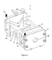
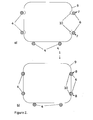
- the present invention discloses a crossflow filtration cassette holder 1;31, which comprises a distributor plate 2;32, an end-plate 3;33, a plurality of essentially parallel tie rods 4,6;34,36 which connect the distributor plate with the end-plate, and a compression plate 5;35 which is slidably mounted on the tie rods between the distributor plate and the end plate.
- At least one 6;36 of the tie rods 4,6;34,36 can be moved in its entirety between a) an open position 7 or orientation 37, where it is possible to mount or remove one or more filtration cassettes 9;39, and b) a closed position 8 or orientation 38, where the movable tie rod is in engaged connection with the cassette and locks it in the holder by a locking means 10;40.
- the locking means are one or more indentations 10;40 on the cassette 9;39, which are adapted to engage a movable tie rod 6;36.
- a cassette or a stack of cassettes can be placed between the tie rods in the cage structure formed by the tie rods and oriented so that the locking means are facing the movable tie rod or tie rods.
- the cassette or stack of cassettes is locked in place and prevented from movement in the plane perpendicular to the tie bars, which would cause leakage during use.
- An advantage of the invention is that the cassette holder is easy to open without disassembling the tie bars and that the tie bars are robust enough to withstand the clamping force needed to ensure sealing.
- Typical clamping forces used with crossflow filtration cassettes can be in the range of 4 - 15 kN, depending on the liquid pressure (e.g. 0 - 4 bar) and the cross section area of the cassettes (e.g. 100 - 350 cm 2 ). When larger cassettes are used, the clamping force may be up to 30 kN. The clamping force is easily applied to the compression plate without disassembling the holder, which emphasizes the need for an easy method to mount and remove cassettes.
- the movable tie bar or tie bars 6;36 can be formed as single piece constructions.
- An advantage of avoiding joints, hinges or similar weak elements in the tie bars is that their strength is increased and also that the risk of jamming due to e.g. corrosion or encrustation is diminished.
- the plates 2,3,5;32,33,35 and/or the tie bars 4,6;34,36, including the movable tie bar or tie bars 6;36 can comprise a ferrous metal such as stainless steel.
- Stainless steels, e.g. 316L and similar qualities are routinely used in bioprocess equipment and it is desirable to be able to use them also for the movable tie bars. If a hinged tie bar according to the prior art is used, the weakness of the hinge must be compensated by using high strength corrosion-resistant materials like titanium, which is highly expensive and also poses difficulties in machining.
- the movable tie rod or tie rods 6;36 have a diameter less than about 20 mm, such as about 10 - 15 mm.
- the indentations 10;40 on most commercially available filtration cassettes are accommodated to engage with tie rods of 10 - 15 mm, which sets a practical limitation on the rod diameters.
- tie rods of diameters less than about 20 mm An advantage of the tie rods of the invention is that even with limited rod diameters they still give sufficient strength to withstand the clamping force.
- At least two 6;36 of the tie rods 4,6;34,36 are movable in their entirety between an open position or orientation and a closed position or orientation.
- at least two tie rods should be movable to allow mounting and removal of the cassettes.
- one movable tie rod can be sufficient, although it is also possible to have two movable tie rods; one on each side of the cassette. In the latter case, an advantage of having tow movable tie rods is that the difference between closed and open position/orientation can be lower for each tie bar. This can allow for more convenient constructions.
- the distributor plate 2;32 comprises retentate 14;44 and permeate 15;45 inlet and outlet connectors, which are fluidically connected with retentate 16 and permeate 17 apertures corresponding to apertures 10;40 on a filtration cassette 9;39.
- a cassette or a stack of cassettes When a cassette or a stack of cassettes is mounted in the holder, it can be placed so that the apertures on the cassette(s) fit the apertures on the distributor plate and any further cassettes are stacked with their apertures in registry. Fluidically connected retentate and permeate loops are then formed to allow for crossflow filtration.
- a distributor plate with retentate and permeate apertures on both sides of the plate. In this case, two end plates will be used, with one cassette or stack of cassettes between each end plate and the distributor plate.
- the retentate inlet may alternatively be called a feed inlet.
- the cassette holder 1;31 also comprises compression means 49, which is arranged to act on the compression plate 5;35.
- the compression means can e.g. comprise a hydraulic cylinder or one or more screws, bolts, threaded rods, cantilevers, excenter clamps etc.
- the compression means may act on the compression plate 5;35 through an opening 18;48 in the end plate 3;33.
- the compression means can provide the clamping force needed to allow for leak-free connection between the cassettes and between the cassettes and the distribution plate.
- the movable tie rod or tie rods 6 are laterally movable, i.e. in a plane essentially parallel to the distribution 2 and end 3 plates and/or essentially perpendicular to the length axes of the tie rods 4,6. They can be movable in a direction essentially towards and away from a cassette 9 placed in the holder 1. Such movement can e.g. be accomplished by having the ends of each movable tie rod 6 slidably connected to the end-plate 2 and the distributor plate 3, e.g. by mounting them through elongated openings 13 in the plates.
- the openings 13 can be elongated in a direction essentially towards and away from a cassette 9 placed in the holder, which allows the tie rod to slide in this direction.
- the movable tie rods can be spring loaded so that they can be moved by an external force and then return e.g. to the locked position through the action of a spring.
- the shape of the openings may e.g. be generally rectangular with two opposite ends capped by circle arcs such as hemicircles.
- the movable tie rods may be freely slidable when no clamping force is applied and locked in place when a compression means acts upon the compression plate.
- the cassette holder 1 comprises pins 11 mounted in the distributor plate 2 and the end plate 3. These pins are arranged to move the laterally movable tie rod or tie rods 6 between an open 7 and a closed 8 position.
- the pins can comprise indentations 12 which engage with the laterally movable tie rod or tie rods 6. When the pins are pushed towards the plates 2,3, the movable tie rods move inwards to a closed position 8, although it is also possible to arrange the pins with the indentations and e.g. spring loaded tie bars so that the tie bars move outwards upon pushing the pins. It is also possible to arrange the pins 11 and the indentations 12 so that the tie bars 6 are laterally moved upon rotation of the pins 11.
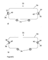
- the movable tie rod or tie rods 36 are mounted to be rotatable around their length axes. They can suitably have a circular cross section in the regions 42 contacting the distributor plate and the end plate and a truncated circle cross section in at least part of the region 41 between the distributor plate 32 and the end plate 33. They are then supported by the distributor and end plates and when they are rotated around the length axes, they move from an open orientation 37 where the truncated part of the circle faces the cassette to a closed orientation 38 where the circular arc faces the cassette and engages in a cassette indentation 40.
- the transition from circular to truncated circle cross section can be gradual, such as with a radius of curvature, to avoid local stress concentration when a clamping force is applied.
- the invention discloses a crossflow filtration module comprising a crossflow filtration cassette holder 1;31 and at least one filtration cassette 9;39 mounted in the holder.
- the holder can be constructed according to any of the embodiments described above and the module may comprise one cassette or a stacked plurality of cassettes.
- the module may be used for e.g. ultrafiltration or microfiltration of fluids in bioprocessing of e.g. biopharmaceuticals or other biomacromolecules. Examples of applications for such a module include buffer exchange by ultrafiltration in a diafiltration mode, concentration of protein solutions, removal of small molecule contaminants from proteins, vaccines etc and removal of particulates from protein solutions.
- the invention discloses a method of mounting a filtration cassette 9;39 in a crossflow filtration cassette holder 1;31.
- the method comprises placing the cassette in the holder and moving at least one tie rod 6;36 in its entirety from an open position 7 or orientation 37 to a closed position 8 or orientation 38 where the tie rod is in a locking engagement with the cassette.
- the holder can be constructed according to any of the embodiments described above.
- the method may also comprise a step of moving at least one tie rod in its entirety from a closed position or orientation to an open position or orientation, to be performed before placing the cassette in the holder.
Landscapes
- Chemical & Material Sciences (AREA)
- Chemical Kinetics & Catalysis (AREA)
- Engineering & Computer Science (AREA)
- Manufacturing & Machinery (AREA)
- Separation Using Semi-Permeable Membranes (AREA)
Applications Claiming Priority (2)
| Application Number | Priority Date | Filing Date | Title |
|---|---|---|---|
| SE1150364 | 2011-04-27 | ||
| PCT/SE2012/050433 WO2012148348A1 (en) | 2011-04-27 | 2012-04-25 | Crossflow filtration cassette holder |
Publications (3)
| Publication Number | Publication Date |
|---|---|
| EP2701828A1 EP2701828A1 (en) | 2014-03-05 |
| EP2701828A4 EP2701828A4 (en) | 2014-10-15 |
| EP2701828B1 true EP2701828B1 (en) | 2016-01-13 |
Family
ID=47072609
Family Applications (1)
| Application Number | Title | Priority Date | Filing Date |
|---|---|---|---|
| EP12777409.9A Active EP2701828B1 (en) | 2011-04-27 | 2012-04-25 | Crossflow filtration cassette holder |
Country Status (5)
| Country | Link |
|---|---|
| US (1) | US9707519B2 (https=) |
| EP (1) | EP2701828B1 (https=) |
| JP (1) | JP6027605B2 (https=) |
| CN (1) | CN103492053B (https=) |
| WO (1) | WO2012148348A1 (https=) |
Cited By (1)
| Publication number | Priority date | Publication date | Assignee | Title |
|---|---|---|---|---|
| US12616937B2 (en) | 2023-02-09 | 2026-05-05 | Repligen Corporation | Filtration units and assembly, and methods of making and using same |
Families Citing this family (9)
| Publication number | Priority date | Publication date | Assignee | Title |
|---|---|---|---|---|
| DE102013112370A1 (de) * | 2013-11-11 | 2015-05-13 | Sartorius Stedim Biotech Gmbh | Verbindungssystem für Filterkassetten |
| CA2957443C (en) | 2014-12-22 | 2022-08-16 | PRO-Equipment, Inc. | Cross flow dynamic membrane filter and disc membrane assembly thereof |
| WO2020123939A1 (en) * | 2018-12-14 | 2020-06-18 | PRO-Equipment, Inc. | High velocity cross flow dynamic membrane filter |
| USD951477S1 (en) * | 2020-04-30 | 2022-05-10 | Puridify Ltd | Purification cassette |
| USD951475S1 (en) * | 2020-04-30 | 2022-05-10 | Puridify Ltd | Purification cassette |
| USD951476S1 (en) * | 2020-04-30 | 2022-05-10 | Puridify Ltd | Purification cassette |
| USD951478S1 (en) * | 2020-04-30 | 2022-05-10 | Puridify Ltd | Purification cassette |
| US12356966B1 (en) * | 2022-03-04 | 2025-07-15 | Dung Minh Hoang | Modular fish tank filter components |
| USD1094639S1 (en) * | 2023-07-24 | 2025-09-23 | Merck Millipore Ltd. | Filter holder |
Family Cites Families (14)
| Publication number | Priority date | Publication date | Assignee | Title |
|---|---|---|---|---|
| US2107805A (en) | 1935-05-21 | 1938-02-08 | Arthur O Russell | Dialyzers |
| DE2556210C3 (de) * | 1975-12-13 | 1978-12-21 | Gesellschaft Fuer Kernenergieverwertung In Schiffbau Und Schiffahrt Mbh, 2000 Hamburg | Einrichtung zur Wasserentsalzung durch Umgekehrte Osmose |
| US4430218A (en) * | 1980-07-18 | 1984-02-07 | Sartorius Gmbh | Separating device for fluids, consisting of support plates and cut sections of a semi-permeable diaphragm |
| US4849102A (en) * | 1988-05-31 | 1989-07-18 | Filtron Technology Corporation | Bidirectional ultrafiltration apparatus |
| CA2498236A1 (en) * | 2002-09-13 | 2004-03-25 | Usfilter Corporation | Heating plate for vacuum filter press |
| JP2006505406A (ja) * | 2002-11-08 | 2006-02-16 | イノヴァセップ・テクノロジー・コーポレーション | 接線濾過ハウジング |
| DE202007002619U1 (de) * | 2006-03-01 | 2007-07-12 | Sartorius Ag | Kassettenstapel-Einspannvorrichtung |
| DE102006009804B4 (de) | 2006-03-01 | 2009-02-12 | Sartorius Stedim Biotech Gmbh | Kassettenstapel-Einspannvorrichtung |
| US8177974B2 (en) * | 2006-04-14 | 2012-05-15 | Emd Millipore Corporation | Disposable tangential flow filtration device holder |
| EP1946825A1 (en) | 2006-12-11 | 2008-07-23 | Pall Corporation | Filtration assemblies and methods of maintaining compression of filtration units in filtration assemblies |
| US20080135499A1 (en) * | 2006-12-11 | 2008-06-12 | Pall Corporation | Filtration assemblies and methods of maintaining compression of filtration units in filtration assemblies |
| ITMS20090002A1 (it) * | 2009-02-10 | 2010-08-11 | Stefano Tongiani | Filtropressa ad azione combinata |
| DK2445616T3 (en) | 2009-06-23 | 2018-06-06 | Ge Healthcare Bio Sciences Ab | SIMULATION DEVICES |
| FR2960162B1 (fr) | 2010-05-19 | 2012-08-17 | Millipore Corp | Dispositif de filtration a jeu d'au moins une cassette filtrante |
-
2012
- 2012-04-25 JP JP2014508317A patent/JP6027605B2/ja active Active
- 2012-04-25 EP EP12777409.9A patent/EP2701828B1/en active Active
- 2012-04-25 WO PCT/SE2012/050433 patent/WO2012148348A1/en not_active Ceased
- 2012-04-25 US US14/113,460 patent/US9707519B2/en active Active
- 2012-04-25 CN CN201280020290.5A patent/CN103492053B/zh active Active
Cited By (1)
| Publication number | Priority date | Publication date | Assignee | Title |
|---|---|---|---|---|
| US12616937B2 (en) | 2023-02-09 | 2026-05-05 | Repligen Corporation | Filtration units and assembly, and methods of making and using same |
Also Published As
| Publication number | Publication date |
|---|---|
| JP2014514961A (ja) | 2014-06-26 |
| EP2701828A1 (en) | 2014-03-05 |
| US20140042069A1 (en) | 2014-02-13 |
| US9707519B2 (en) | 2017-07-18 |
| CN103492053B (zh) | 2015-12-23 |
| EP2701828A4 (en) | 2014-10-15 |
| WO2012148348A1 (en) | 2012-11-01 |
| JP6027605B2 (ja) | 2016-11-16 |
| CN103492053A (zh) | 2014-01-01 |
Similar Documents
| Publication | Publication Date | Title |
|---|---|---|
| EP2701828B1 (en) | Crossflow filtration cassette holder | |
| EP2476479A1 (en) | Method of non-destructive inspection of flat membrane | |
| DE69623451T2 (de) | Filter mit darin enthaltener filtrationskassette | |
| US9447911B2 (en) | Adjustable frame assemblies, methods for assembling a filter apparatus, and filter apparatuses | |
| DE10005427A1 (de) | Vorrichtung zur gleichzeitigen Filtration einer Vielzahl von Flüssigkeitsproben | |
| CN100404113C (zh) | 使用多膜过滤器将流体分离成至少两部分的设备及其用途 | |
| US7635426B2 (en) | Tangential filtration housing | |
| EP2388062B1 (en) | Manifold for a device for filtration with a set of least one filter cassette | |
| US20140305860A1 (en) | Distribution plate for crossflow filtration cassettes | |
| EP1758666B1 (en) | Fluid treatment arrangements and methods for operating fluid treatment arrangements | |
| EP2559477B1 (de) | Vorrichtung zum Filtern und Trennen von Strömungsmedien mittels Hohlfadenmembranelementen | |
| US20150096930A1 (en) | Separation membrane module and replacement method for separation membrane element | |
| WO2006130815A2 (en) | Crossflow membrane filtration module | |
| AU2013204302B2 (en) | Method of Non-Destructive Inspection of Flat Membrane | |
| CN114618229A (zh) | 一种纳滤膜分离工艺及设备 | |
| CN221644661U (zh) | 一种纯水系统浓水再利用装置 | |
| WO2026073021A2 (en) | Stacked-plate filter assemblies and filter plates therefore | |
| KR20230175243A (ko) | 필터 박스 및 필터 박스를 갖는 회수 가능한 해저 필터 모듈 | |
| EP1946824B1 (en) | Filtration assemblies with common manifold and use therof |
Legal Events
| Date | Code | Title | Description |
|---|---|---|---|
| PUAI | Public reference made under article 153(3) epc to a published international application that has entered the european phase |
Free format text: ORIGINAL CODE: 0009012 |
|
| 17P | Request for examination filed |
Effective date: 20131015 |
|
| AK | Designated contracting states |
Kind code of ref document: A1 Designated state(s): AL AT BE BG CH CY CZ DE DK EE ES FI FR GB GR HR HU IE IS IT LI LT LU LV MC MK MT NL NO PL PT RO RS SE SI SK SM TR |
|
| DAX | Request for extension of the european patent (deleted) | ||
| A4 | Supplementary search report drawn up and despatched |
Effective date: 20140916 |
|
| RIC1 | Information provided on ipc code assigned before grant |
Ipc: B01D 65/00 20060101ALI20140910BHEP Ipc: B01D 63/08 20060101AFI20140910BHEP |
|
| GRAP | Despatch of communication of intention to grant a patent |
Free format text: ORIGINAL CODE: EPIDOSNIGR1 |
|
| INTG | Intention to grant announced |
Effective date: 20150807 |
|
| GRAS | Grant fee paid |
Free format text: ORIGINAL CODE: EPIDOSNIGR3 |
|
| GRAA | (expected) grant |
Free format text: ORIGINAL CODE: 0009210 |
|
| AK | Designated contracting states |
Kind code of ref document: B1 Designated state(s): AL AT BE BG CH CY CZ DE DK EE ES FI FR GB GR HR HU IE IS IT LI LT LU LV MC MK MT NL NO PL PT RO RS SE SI SK SM TR |
|
| REG | Reference to a national code |
Ref country code: GB Ref legal event code: FG4D |
|
| REG | Reference to a national code |
Ref country code: CH Ref legal event code: EP |
|
| REG | Reference to a national code |
Ref country code: IE Ref legal event code: FG4D |
|
| REG | Reference to a national code |
Ref country code: AT Ref legal event code: REF Ref document number: 770132 Country of ref document: AT Kind code of ref document: T Effective date: 20160215 |
|
| REG | Reference to a national code |
Ref country code: DE Ref legal event code: R096 Ref document number: 602012013954 Country of ref document: DE |
|
| REG | Reference to a national code |
Ref country code: FR Ref legal event code: PLFP Year of fee payment: 5 |
|
| REG | Reference to a national code |
Ref country code: LT Ref legal event code: MG4D |
|
| REG | Reference to a national code |
Ref country code: NL Ref legal event code: MP Effective date: 20160113 |
|
| REG | Reference to a national code |
Ref country code: AT Ref legal event code: MK05 Ref document number: 770132 Country of ref document: AT Kind code of ref document: T Effective date: 20160113 |
|
| PG25 | Lapsed in a contracting state [announced via postgrant information from national office to epo] |
Ref country code: NL Free format text: LAPSE BECAUSE OF FAILURE TO SUBMIT A TRANSLATION OF THE DESCRIPTION OR TO PAY THE FEE WITHIN THE PRESCRIBED TIME-LIMIT Effective date: 20160113 |
|
| PG25 | Lapsed in a contracting state [announced via postgrant information from national office to epo] |
Ref country code: FI Free format text: LAPSE BECAUSE OF FAILURE TO SUBMIT A TRANSLATION OF THE DESCRIPTION OR TO PAY THE FEE WITHIN THE PRESCRIBED TIME-LIMIT Effective date: 20160113 Ref country code: GR Free format text: LAPSE BECAUSE OF FAILURE TO SUBMIT A TRANSLATION OF THE DESCRIPTION OR TO PAY THE FEE WITHIN THE PRESCRIBED TIME-LIMIT Effective date: 20160414 Ref country code: IT Free format text: LAPSE BECAUSE OF FAILURE TO SUBMIT A TRANSLATION OF THE DESCRIPTION OR TO PAY THE FEE WITHIN THE PRESCRIBED TIME-LIMIT Effective date: 20160113 Ref country code: HR Free format text: LAPSE BECAUSE OF FAILURE TO SUBMIT A TRANSLATION OF THE DESCRIPTION OR TO PAY THE FEE WITHIN THE PRESCRIBED TIME-LIMIT Effective date: 20160113 Ref country code: ES Free format text: LAPSE BECAUSE OF FAILURE TO SUBMIT A TRANSLATION OF THE DESCRIPTION OR TO PAY THE FEE WITHIN THE PRESCRIBED TIME-LIMIT Effective date: 20160113 Ref country code: NO Free format text: LAPSE BECAUSE OF FAILURE TO SUBMIT A TRANSLATION OF THE DESCRIPTION OR TO PAY THE FEE WITHIN THE PRESCRIBED TIME-LIMIT Effective date: 20160413 |
|
| PG25 | Lapsed in a contracting state [announced via postgrant information from national office to epo] |
Ref country code: LT Free format text: LAPSE BECAUSE OF FAILURE TO SUBMIT A TRANSLATION OF THE DESCRIPTION OR TO PAY THE FEE WITHIN THE PRESCRIBED TIME-LIMIT Effective date: 20160113 Ref country code: RS Free format text: LAPSE BECAUSE OF FAILURE TO SUBMIT A TRANSLATION OF THE DESCRIPTION OR TO PAY THE FEE WITHIN THE PRESCRIBED TIME-LIMIT Effective date: 20160113 Ref country code: BE Free format text: LAPSE BECAUSE OF NON-PAYMENT OF DUE FEES Effective date: 20160430 Ref country code: AT Free format text: LAPSE BECAUSE OF FAILURE TO SUBMIT A TRANSLATION OF THE DESCRIPTION OR TO PAY THE FEE WITHIN THE PRESCRIBED TIME-LIMIT Effective date: 20160113 Ref country code: LV Free format text: LAPSE BECAUSE OF FAILURE TO SUBMIT A TRANSLATION OF THE DESCRIPTION OR TO PAY THE FEE WITHIN THE PRESCRIBED TIME-LIMIT Effective date: 20160113 Ref country code: IS Free format text: LAPSE BECAUSE OF FAILURE TO SUBMIT A TRANSLATION OF THE DESCRIPTION OR TO PAY THE FEE WITHIN THE PRESCRIBED TIME-LIMIT Effective date: 20160513 Ref country code: PL Free format text: LAPSE BECAUSE OF FAILURE TO SUBMIT A TRANSLATION OF THE DESCRIPTION OR TO PAY THE FEE WITHIN THE PRESCRIBED TIME-LIMIT Effective date: 20160113 Ref country code: PT Free format text: LAPSE BECAUSE OF FAILURE TO SUBMIT A TRANSLATION OF THE DESCRIPTION OR TO PAY THE FEE WITHIN THE PRESCRIBED TIME-LIMIT Effective date: 20160513 Ref country code: SE Free format text: LAPSE BECAUSE OF FAILURE TO SUBMIT A TRANSLATION OF THE DESCRIPTION OR TO PAY THE FEE WITHIN THE PRESCRIBED TIME-LIMIT Effective date: 20160113 |
|
| REG | Reference to a national code |
Ref country code: DE Ref legal event code: R097 Ref document number: 602012013954 Country of ref document: DE |
|
| PG25 | Lapsed in a contracting state [announced via postgrant information from national office to epo] |
Ref country code: EE Free format text: LAPSE BECAUSE OF FAILURE TO SUBMIT A TRANSLATION OF THE DESCRIPTION OR TO PAY THE FEE WITHIN THE PRESCRIBED TIME-LIMIT Effective date: 20160113 Ref country code: DK Free format text: LAPSE BECAUSE OF FAILURE TO SUBMIT A TRANSLATION OF THE DESCRIPTION OR TO PAY THE FEE WITHIN THE PRESCRIBED TIME-LIMIT Effective date: 20160113 |
|
| PLBE | No opposition filed within time limit |
Free format text: ORIGINAL CODE: 0009261 |
|
| STAA | Information on the status of an ep patent application or granted ep patent |
Free format text: STATUS: NO OPPOSITION FILED WITHIN TIME LIMIT |
|
| PG25 | Lapsed in a contracting state [announced via postgrant information from national office to epo] |
Ref country code: SK Free format text: LAPSE BECAUSE OF FAILURE TO SUBMIT A TRANSLATION OF THE DESCRIPTION OR TO PAY THE FEE WITHIN THE PRESCRIBED TIME-LIMIT Effective date: 20160113 Ref country code: RO Free format text: LAPSE BECAUSE OF FAILURE TO SUBMIT A TRANSLATION OF THE DESCRIPTION OR TO PAY THE FEE WITHIN THE PRESCRIBED TIME-LIMIT Effective date: 20160113 Ref country code: CZ Free format text: LAPSE BECAUSE OF FAILURE TO SUBMIT A TRANSLATION OF THE DESCRIPTION OR TO PAY THE FEE WITHIN THE PRESCRIBED TIME-LIMIT Effective date: 20160113 Ref country code: SM Free format text: LAPSE BECAUSE OF FAILURE TO SUBMIT A TRANSLATION OF THE DESCRIPTION OR TO PAY THE FEE WITHIN THE PRESCRIBED TIME-LIMIT Effective date: 20160113 |
|
| REG | Reference to a national code |
Ref country code: CH Ref legal event code: PL |
|
| 26N | No opposition filed |
Effective date: 20161014 |
|
| PG25 | Lapsed in a contracting state [announced via postgrant information from national office to epo] |
Ref country code: BE Free format text: LAPSE BECAUSE OF FAILURE TO SUBMIT A TRANSLATION OF THE DESCRIPTION OR TO PAY THE FEE WITHIN THE PRESCRIBED TIME-LIMIT Effective date: 20160113 Ref country code: LU Free format text: LAPSE BECAUSE OF FAILURE TO SUBMIT A TRANSLATION OF THE DESCRIPTION OR TO PAY THE FEE WITHIN THE PRESCRIBED TIME-LIMIT Effective date: 20160425 |
|
| REG | Reference to a national code |
Ref country code: IE Ref legal event code: MM4A |
|
| PG25 | Lapsed in a contracting state [announced via postgrant information from national office to epo] |
Ref country code: LI Free format text: LAPSE BECAUSE OF NON-PAYMENT OF DUE FEES Effective date: 20160430 Ref country code: CH Free format text: LAPSE BECAUSE OF NON-PAYMENT OF DUE FEES Effective date: 20160430 |
|
| PG25 | Lapsed in a contracting state [announced via postgrant information from national office to epo] |
Ref country code: SI Free format text: LAPSE BECAUSE OF FAILURE TO SUBMIT A TRANSLATION OF THE DESCRIPTION OR TO PAY THE FEE WITHIN THE PRESCRIBED TIME-LIMIT Effective date: 20160113 Ref country code: BG Free format text: LAPSE BECAUSE OF FAILURE TO SUBMIT A TRANSLATION OF THE DESCRIPTION OR TO PAY THE FEE WITHIN THE PRESCRIBED TIME-LIMIT Effective date: 20160413 |
|
| REG | Reference to a national code |
Ref country code: FR Ref legal event code: PLFP Year of fee payment: 6 |
|
| PG25 | Lapsed in a contracting state [announced via postgrant information from national office to epo] |
Ref country code: IE Free format text: LAPSE BECAUSE OF NON-PAYMENT OF DUE FEES Effective date: 20160425 |
|
| REG | Reference to a national code |
Ref country code: FR Ref legal event code: PLFP Year of fee payment: 7 |
|
| PG25 | Lapsed in a contracting state [announced via postgrant information from national office to epo] |
Ref country code: HU Free format text: LAPSE BECAUSE OF FAILURE TO SUBMIT A TRANSLATION OF THE DESCRIPTION OR TO PAY THE FEE WITHIN THE PRESCRIBED TIME-LIMIT; INVALID AB INITIO Effective date: 20120425 Ref country code: CY Free format text: LAPSE BECAUSE OF FAILURE TO SUBMIT A TRANSLATION OF THE DESCRIPTION OR TO PAY THE FEE WITHIN THE PRESCRIBED TIME-LIMIT Effective date: 20160113 |
|
| PG25 | Lapsed in a contracting state [announced via postgrant information from national office to epo] |
Ref country code: MK Free format text: LAPSE BECAUSE OF FAILURE TO SUBMIT A TRANSLATION OF THE DESCRIPTION OR TO PAY THE FEE WITHIN THE PRESCRIBED TIME-LIMIT Effective date: 20160113 Ref country code: TR Free format text: LAPSE BECAUSE OF FAILURE TO SUBMIT A TRANSLATION OF THE DESCRIPTION OR TO PAY THE FEE WITHIN THE PRESCRIBED TIME-LIMIT Effective date: 20160113 Ref country code: MC Free format text: LAPSE BECAUSE OF FAILURE TO SUBMIT A TRANSLATION OF THE DESCRIPTION OR TO PAY THE FEE WITHIN THE PRESCRIBED TIME-LIMIT Effective date: 20160113 Ref country code: MT Free format text: LAPSE BECAUSE OF NON-PAYMENT OF DUE FEES Effective date: 20160430 |
|
| PG25 | Lapsed in a contracting state [announced via postgrant information from national office to epo] |
Ref country code: AL Free format text: LAPSE BECAUSE OF FAILURE TO SUBMIT A TRANSLATION OF THE DESCRIPTION OR TO PAY THE FEE WITHIN THE PRESCRIBED TIME-LIMIT Effective date: 20160113 |
|
| REG | Reference to a national code |
Ref country code: DE Ref legal event code: R081 Ref document number: 602012013954 Country of ref document: DE Owner name: CYTIVA SWEDEN AB, SE Free format text: FORMER OWNER: GE HEALTHCARE BIO-SCIENCES AB, UPPSALA, SE |
|
| P01 | Opt-out of the competence of the unified patent court (upc) registered |
Effective date: 20230526 |
|
| PGFP | Annual fee paid to national office [announced via postgrant information from national office to epo] |
Ref country code: DE Payment date: 20250428 Year of fee payment: 14 |
|
| PGFP | Annual fee paid to national office [announced via postgrant information from national office to epo] |
Ref country code: FR Payment date: 20250424 Year of fee payment: 14 |
|
| PGFP | Annual fee paid to national office [announced via postgrant information from national office to epo] |
Ref country code: GB Payment date: 20260223 Year of fee payment: 15 |