EP2701425A1 - Method, device, and system for reporting channel quality indicator - Google Patents
Method, device, and system for reporting channel quality indicator Download PDFInfo
- Publication number
- EP2701425A1 EP2701425A1 EP12774811.9A EP12774811A EP2701425A1 EP 2701425 A1 EP2701425 A1 EP 2701425A1 EP 12774811 A EP12774811 A EP 12774811A EP 2701425 A1 EP2701425 A1 EP 2701425A1
- Authority
- EP
- European Patent Office
- Prior art keywords
- user equipment
- channel matrix
- measurement set
- sub
- cqi
- Prior art date
- Legal status (The legal status is an assumption and is not a legal conclusion. Google has not performed a legal analysis and makes no representation as to the accuracy of the status listed.)
- Granted
Links
Images




Classifications
-
- H—ELECTRICITY
- H04—ELECTRIC COMMUNICATION TECHNIQUE
- H04W—WIRELESS COMMUNICATION NETWORKS
- H04W24/00—Supervisory, monitoring or testing arrangements
- H04W24/10—Scheduling measurement reports ; Arrangements for measurement reports
-
- H—ELECTRICITY
- H04—ELECTRIC COMMUNICATION TECHNIQUE
- H04L—TRANSMISSION OF DIGITAL INFORMATION, e.g. TELEGRAPHIC COMMUNICATION
- H04L5/00—Arrangements affording multiple use of the transmission path
- H04L5/003—Arrangements for allocating sub-channels of the transmission path
- H04L5/0032—Distributed allocation, i.e. involving a plurality of allocating devices, each making partial allocation
- H04L5/0035—Resource allocation in a cooperative multipoint environment
-
- H—ELECTRICITY
- H04—ELECTRIC COMMUNICATION TECHNIQUE
- H04J—MULTIPLEX COMMUNICATION
- H04J11/00—Orthogonal multiplex systems, e.g. using WALSH codes
- H04J11/0023—Interference mitigation or co-ordination
- H04J11/005—Interference mitigation or co-ordination of intercell interference
- H04J11/0053—Interference mitigation or co-ordination of intercell interference using co-ordinated multipoint transmission/reception
-
- H—ELECTRICITY
- H04—ELECTRIC COMMUNICATION TECHNIQUE
- H04L—TRANSMISSION OF DIGITAL INFORMATION, e.g. TELEGRAPHIC COMMUNICATION
- H04L1/00—Arrangements for detecting or preventing errors in the information received
- H04L1/0001—Systems modifying transmission characteristics according to link quality, e.g. power backoff
- H04L1/0015—Systems modifying transmission characteristics according to link quality, e.g. power backoff characterised by the adaptation strategy
- H04L1/0019—Systems modifying transmission characteristics according to link quality, e.g. power backoff characterised by the adaptation strategy in which mode-switching is based on a statistical approach
-
- H—ELECTRICITY
- H04—ELECTRIC COMMUNICATION TECHNIQUE
- H04L—TRANSMISSION OF DIGITAL INFORMATION, e.g. TELEGRAPHIC COMMUNICATION
- H04L1/00—Arrangements for detecting or preventing errors in the information received
- H04L1/0001—Systems modifying transmission characteristics according to link quality, e.g. power backoff
- H04L1/0023—Systems modifying transmission characteristics according to link quality, e.g. power backoff characterised by the signalling
- H04L1/0026—Transmission of channel quality indication
-
- H—ELECTRICITY
- H04—ELECTRIC COMMUNICATION TECHNIQUE
- H04L—TRANSMISSION OF DIGITAL INFORMATION, e.g. TELEGRAPHIC COMMUNICATION
- H04L1/00—Arrangements for detecting or preventing errors in the information received
- H04L1/0001—Systems modifying transmission characteristics according to link quality, e.g. power backoff
- H04L1/0033—Systems modifying transmission characteristics according to link quality, e.g. power backoff arrangements specific to the transmitter
- H04L1/0035—Systems modifying transmission characteristics according to link quality, e.g. power backoff arrangements specific to the transmitter evaluation of received explicit signalling
-
- H—ELECTRICITY
- H04—ELECTRIC COMMUNICATION TECHNIQUE
- H04L—TRANSMISSION OF DIGITAL INFORMATION, e.g. TELEGRAPHIC COMMUNICATION
- H04L1/00—Arrangements for detecting or preventing errors in the information received
- H04L1/004—Arrangements for detecting or preventing errors in the information received by using forward error control
- H04L1/0076—Distributed coding, e.g. network coding, involving channel coding
- H04L1/0077—Cooperative coding
-
- H—ELECTRICITY
- H04—ELECTRIC COMMUNICATION TECHNIQUE
- H04L—TRANSMISSION OF DIGITAL INFORMATION, e.g. TELEGRAPHIC COMMUNICATION
- H04L1/00—Arrangements for detecting or preventing errors in the information received
- H04L1/20—Arrangements for detecting or preventing errors in the information received using signal quality detector
-
- H—ELECTRICITY
- H04—ELECTRIC COMMUNICATION TECHNIQUE
- H04L—TRANSMISSION OF DIGITAL INFORMATION, e.g. TELEGRAPHIC COMMUNICATION
- H04L5/00—Arrangements affording multiple use of the transmission path
- H04L5/003—Arrangements for allocating sub-channels of the transmission path
- H04L5/0058—Allocation criteria
- H04L5/0073—Allocation arrangements that take into account other cell interferences
-
- H—ELECTRICITY
- H04—ELECTRIC COMMUNICATION TECHNIQUE
- H04W—WIRELESS COMMUNICATION NETWORKS
- H04W24/00—Supervisory, monitoring or testing arrangements
- H04W24/02—Arrangements for optimising operational condition
-
- H—ELECTRICITY
- H04—ELECTRIC COMMUNICATION TECHNIQUE
- H04L—TRANSMISSION OF DIGITAL INFORMATION, e.g. TELEGRAPHIC COMMUNICATION
- H04L1/00—Arrangements for detecting or preventing errors in the information received
- H04L1/0001—Systems modifying transmission characteristics according to link quality, e.g. power backoff
- H04L1/0002—Systems modifying transmission characteristics according to link quality, e.g. power backoff by adapting the transmission rate
- H04L1/0003—Systems modifying transmission characteristics according to link quality, e.g. power backoff by adapting the transmission rate by switching between different modulation schemes
-
- H—ELECTRICITY
- H04—ELECTRIC COMMUNICATION TECHNIQUE
- H04L—TRANSMISSION OF DIGITAL INFORMATION, e.g. TELEGRAPHIC COMMUNICATION
- H04L1/00—Arrangements for detecting or preventing errors in the information received
- H04L1/0001—Systems modifying transmission characteristics according to link quality, e.g. power backoff
- H04L1/0009—Systems modifying transmission characteristics according to link quality, e.g. power backoff by adapting the channel coding
-
- H—ELECTRICITY
- H04—ELECTRIC COMMUNICATION TECHNIQUE
- H04L—TRANSMISSION OF DIGITAL INFORMATION, e.g. TELEGRAPHIC COMMUNICATION
- H04L1/00—Arrangements for detecting or preventing errors in the information received
- H04L2001/0092—Error control systems characterised by the topology of the transmission link
-
- H—ELECTRICITY
- H04—ELECTRIC COMMUNICATION TECHNIQUE
- H04W—WIRELESS COMMUNICATION NETWORKS
- H04W72/00—Local resource management
-
- H—ELECTRICITY
- H04—ELECTRIC COMMUNICATION TECHNIQUE
- H04W—WIRELESS COMMUNICATION NETWORKS
- H04W72/00—Local resource management
- H04W72/12—Wireless traffic scheduling
Definitions
- the present invention relates to the field of communications and particularly to a method, apparatus and system for reporting a channel quality indicator.
- a base station in communication with a User Equipment (UE) in each cell.
- UE User Equipment
- Various user equipments include a mobile phone, a notebook, a Personal Digital Assistant (PDA), etc.
- the base station may transmit a reference signal (e.g., a pilot signal) to the user equipment, and the user equipment may derive a channel estimation value from the reference signal.
- the reference signal is a known signal sequence transmitted at a specific time and a specific frequency as prescribed, and the quality of channel estimation may be influenced by interference, noise and other factors.
- user equipments are located at different geographic positions and are subjected to different received signal strength and different noise and interference strength. Thus some user equipments may communicate at a higher rate, for example, a user equipment located at the center of the cell, and some other user equipments can only communicate at a lower rate, for example, a user equipment located at the edge of the cell.
- data is transmitted to the user equipment preferably in a format matching a channel condition of the user equipment, and a technology to match the format, in which data is transmitted to the user equipment, with a channel condition of the user equipment is referred to link adaptation.
- the user equipment In order to assist the base station in link adaptation, the user equipment needs to report a Channel Quality Indicator (CQI) according to a channel condition of the user equipment.
- CQI Channel Quality Indicator
- the CQI reported by the user equipment corresponds to a specific time-frequency resource, that is, the CQI reported by the user equipment represents a transmission capacity on the time-frequency resource.
- P is received signal power of the user equipment
- Q ( ⁇ ) is a quantization function
- the user equipment may measure the sum of I and No, i.e., I + N 0 .
- CoMP Coordinated Multipoint Transmission/Reception
- Coordinated scheduling refers to that the respective base stations coordinate time, frequency and space resources between the cells to allocate mutually orthogonal resources for different UEs to thereby avoid mutual interference.
- Inter-cell interference is a predominant factor restricting the performance of a cell edge UE, and inter-cell interference can be lowered through coordinated scheduling to thereby improve the performance of the cell edge UE.
- coordinated scheduling of three cells can schedule three UEs possibly interfering with each other onto mutually orthogonal resources to thereby effectively avoid interference between the cells.
- Joint transmission refers to concurrent transmission of data from multiple cells to a UE to thereby enhance a received signal of the UE.
- data is transmitted from three cells to the same UE on the same resource, and the UE receives signals from the multiple cells concurrently.
- superposition of the useful signals from the multiple cells can improve the quality of the signals received by the UE.
- interference to which the UE is subjected can be lowered to thereby improve the performance of a system.
- a UE estimates channel information of a base station to the UE (e.g., a signal matrix, interference, noise, etc.) according to a Cell-specific Reference Signal (CRS) or a Channel State Information-Reference Signal (CSI-RS) of a serving cell, calculates a CQI, and feeds the CQI back to the base station, possibly together with a Pre-coding Matrix Index (PMI) and an Rank Indicator (RI).
- the base station can perform scheduling, resource allocation, Modulation and Coding Scheme (MCS) selection and other operations using the feedback of the CQI to thereby improve the spectral efficiency.
- MCS Modulation and Coding Scheme
- the UE estimates channel information of cells included in a preconfigured measurement set to the UE according to CRSs or CSI-RSs transmitted from the respective cells, and next the UE directly scalar-quantizes or vector-quantizes the channel information and then feeds it back to the base stations, and the base stations perform pre-coding matrix calculation, multi-user pairing, MCS selection and other operations according to the channel information fed back from the UE.
- a base station can derive uplink channel information from a Sounding Reference Signal (SRS) transmitted from a UE and derive downlink channel information by the reciprocity of uplink and downlink channels.
- SRS Sounding Reference Signal
- the base station can not accurately select an MCS and perform frequency-domain scheduling for the UE simply according to the channel information derived from the SRS because the uplink and the downlink are subjected to typically different interference and the base station can not accurately predicate interference to which the UE is subjected; and on the other hand, in the existing TDD system, the base station can not accurately select an MCS and perform frequency-domain scheduling for the UE even according to the channel information fed back from the UE because an interference level of an adjacent cell before scheduling is different from that after scheduling due to the use of the CoMP technology as well as beam shaping and other schemes so that the UE can not predicate a changed interference level after scheduling upon feeding back the channel information.
- Embodiments of the invention provide a method, apparatus and system for reporting a channel quality indicator so as to address the problem in the technology of multipoint coordinated transmission that the network side has no accurate knowledge of interference to which a user equipment is subjected and consequently fails to correctly perform resource allocation and scheduling.
- the user equipment feeds the initial CQIs of the respective devices in the measurement set back to a base station in the network-side apparatus according to the measurement reference signals transmitted from the respective devices in the measurement set, and the network-side apparatus calculates the target CQI of the user equipment according to the initial CQIs of the respective devices fed back from the user equipment and the channel matrix reference information fed back from the user equipment, thereby addressing the problem of feeding back a CQI for multipoint coordinated transmission so that the network-side apparatus can derive the target CQI finally used for downlink transmission of data based upon the initial CQIs of the multiple devices fed back from the user equipment, and thus the network side can have accurate knowledge of interference to which the user equipment is subjected and further correctly perform user equipment scheduling, resource allocation and MCS selection to thereby effectively improve the throughout of the system in multipoint coordinated transmission and improve the performance of the system.
- the present embodiments will be equally applicable to both a TDD system and an FDD system.
- the user equipment needs to measure initial CQIs for respective devices in a measurement set, to report the initial CQIs of the respective devices to a network-side apparatus and to transmit channel matrix reference information to the network-side apparatus so that the network-side apparatus calculates a target CQI of the user equipment based upon the received initial CQIs of the respective devices and channel matrix reference information.
- the measurement set includes a first device transmitting service data to the user equipment and at least one second device participating in multipoint coordinated transmission to the user equipment; and the first device and the second device can be base stations of different cells or can be base stations of the same cell.
- the network-side apparatus can be the first device in the measurement set or can be any one or more devices in the measurement set (which can be the first device or the second device) or can be a central control node connected with all the devices in the measurement set.
- a CoMP-enabled communication system (which can be a TDD system or an FDD system) includes a user equipment and several transmission devices, and there is a multipoint coordinated transmission relationship (which can be either a coordinated scheduling relationship or a joint transmission relationship) between these transmission devices, where one of the transmission devices, i.e., the first device, transmits service data to the user equipment, and the other transmission devices, i.e., the second devices, also participate in multipoint coordinated transmission to the user equipment; and a measurement set for the user equipment is composed of the first device and the at least one second devices, and during network registration of the user equipment, the measurement set is notified in advance from the network side to the user equipment and stored in the user equipment, and the user equipment needs to measure channel information for each device in the measurement set so that the network side accurately estimates interference to which the user equipment is subjected.
- a multipoint coordinated transmission relationship which can be either a coordinated scheduling relationship or a joint transmission relationship
- the user equipment is configured to determine a measurement set used by the user equipment, the measurement set including the first device transmitting service data to the user equipment and the at least one second device participating in multipoint coordinated transmission to the user equipment, to receive a measurement reference signal transmitted from each device in the measurement set respectively, to measure an initial CQI of each device respectively based upon the measurement reference signal transmitted from the corresponding device, to transmit the derived initial CQIs of the respective devices to a network-side apparatus, and to transmit also channel matrix reference information to the network-side apparatus so that the network-side apparatus calculates a target CQI of the user equipment based upon the received initial CQIs of the respective devices and channel matrix reference information; and
- the network-side apparatus is configured to receive the initial CQIs, of the respective devices in the measurement set, transmitted from the user equipment, to receive the channel matrix reference information originating from the user equipment, and to calculate the target CQI of the user equipment based upon the received initial CQIs of the respective devices and channel matrix reference information.
- a user equipment includes a determining unit 40, a receiving unit 41, a measuring unit 42 and a transmitting unit 43, where:
- the determining unit 40 is configured to determine a measurement set used by the user equipment, where the measurement set includes a first device transmitting service data to the user equipment and at least one second device participating in multipoint coordinated transmission to the user equipment; the receiving unit 41 is configured to receive a measurement reference signal transmitted from each device in the measurement set respectively;
- the measuring unit 42 is configured to measure an initial CQI of each device respectively based upon the measurement reference signal transmitted from the corresponding device;
- the transmitting unit 43 is configured to transmit the derived initial CQIs of the respective devices to the network-side apparatus and to transmit channel matrix reference information to the network-side apparatus so that the network-side apparatus calculates a target CQI of the user equipment based upon the received initial CQIs of the respective devices and channel matrix reference information.
- the network-side apparatus includes a communicating unit 50 and a processing unit 51, where:
- a user equipment reports a CQI to the network side in the following detailed flow:
- the measurement set used by the user equipment can be transmitted to the user equipment after being configured by a base station, and the user equipment determines the measurement set according to an indicator of the base station, for example, the base station notifies a particular measurement set in downlink signaling; or the measurement set can be configured by the user equipment itself in a pattern prescribed with the network side.
- the measurement reference signal, transmitted from each device, received by the user equipment includes a CRS and/or a CSI-RS transmitted from the corresponding device.
- Step 620 The user equipment transmits the derived initial CQIs of the respective devices to the network-side apparatus and transmits channel matrix reference information to the network-side apparatus so that the network-side apparatus calculates a target CQI of the user equipment (that is, a CQI from which the network side finally performs resource scheduling and MCS selection for the user equipment) based upon the received initial CQIs of the respective devices and channel matrix reference information.
- a target CQI of the user equipment that is, a CQI from which the network side finally performs resource scheduling and MCS selection for the user equipment
- the target CQI of the user equipment can be calculated in the first device or can be calculated in any one or more devices in the measurement set or can be calculated in a central control node connected with all the devices in the measurement set, that is, the network-side apparatus can be the first device, or any one or more devices in the measurement set, or the central control node.
- the user equipment transmitting the derived initial CQIs of the respective devices to the network-side apparatus refers to that the user equipment transmitting the derived initial CQIs of the respective devices to the first device on an uplink channel or to the any one or more devices in the measurement set (which can include either the first device or the second device) or to the central control node connected with all the devices in the measurement set.
- the user equipment can transmit the channel matrix reference information to the network-side apparatus in (including but not limited to) the following two approaches:
- the user equipment transmits an SRS after transmitting the derived initial CQIs of the respective devices to the network-side apparatus so that each device in the measurement set derives an uplink channel matrix of the user equipment to the corresponding device based upon the received SRS and derives a corresponding downlink channel matrix based upon channel reciprocity and then transmits its own derived downlink channel matrix to the network-side apparatus as the channel matrix reference information.
- the user equipment transmits channel matrices, derived respectively based upon a downlink reference symbol of each device in the measurement set, to the network-side apparatus as the channel matrix reference information after transmitting the derived initial CQIs of the respective devices to the network-side apparatus. At this time the user equipment needs not to transmit an SRS.
- ⁇ qi ( k ) can alternatively be a channel matrix derived by the base station from a feedback by the user equipment, and at this time, the user equipment needs not to transmit an SRS signal.
- a network-side apparatus processes a CQI reported from a user equipment in the following detailed flow:
- Step 700 The network-side apparatus receives initial CQIs, of respective devices in a measurement set, transmitted from the user equipment, where the measurement set includes a serving device of the user equipment and a coordinating device participating in multipoint coordinated transmission to the user equipment.
- Alike the network-side apparatus can be the first device in the measurement set or can be any one or more devices in the measurement set or can be a central control node connected with all the devices in the measurement set. If it is more than one base station, then the respective base stations operate under the same principle.
- Step 710 The network side receives channel matrix reference information originating from the user equipment and calculates a target CQI of the user equipment based upon the received initial CQIs of the respective devices and channel matrix reference information.
- the network-side apparatus can also receive channel matrix reference information originating from the user equipment in (including but not limited to) the following two approaches:
- each device in the measurement set derives a corresponding uplink channel matrix respectively based upon an SRS received from the user equipment and derives a corresponding downlink channel matrix respectively based upon channel reciprocity
- the network-side apparatus receives the downlink channel matrix transmitted from each device respectively and takes the respective downlink channel matrices as the channel matrix reference information.
- the network-side apparatus receives channel matrices, transmitted from the user equipment, derived respectively based upon a downlink reference symbol of each device in the measurement set and takes the respective channel matrices as the channel matrix reference information.
- the network-side apparatus calculates a target CQI of the user equipment based upon the received initial CQIs of the respective devices and channel matrix reference information particularly as follows: after scheduling is performed by the respective devices in the measurement set (scheduling here can be CoMP-based scheduling or single-device scheduling), the network-side apparatus firstly calculates target CQIs of the user equipment on respective sub-carriers and then maps the derived target CQIs on the respective sub-carriers to a unified value, where:
- ⁇ ⁇ q k ⁇ ⁇ qi ⁇ ⁇ H ⁇ qi k ⁇ w l ⁇ 2 / N R , q + 1
- the target CQI of the user equipment on any sub-carrier can be calculated in Formula 3:
- the network-side apparatus maps ⁇ q ( k ) of the respective sub-carriers to a single CQI value, and here the base station can determine for the user equipment an MCS and a frequency-domain resource for downlink transmission of data based upon the derived single CQI value.
- scheduling by the respective devices in the measurement set can be coordinated scheduling or separate single-device scheduling, and for these scenarios, particularly the latter, the use of the technical solution according to the embodiments of the invention can improve their or its accuracy of CQI calculation and MCS selection to thereby improve the performance of the entire system.
- the user equipment feeds the initial CQIs of the respective devices in the measurement set back to the base station in the network-side apparatus according to the measurement reference signals transmitted from the respective devices in the measurement set, and the network-side apparatus calculates the target CQI of the user equipment according to the initial CQIs of the respective devices fed back from the user equipment and the channel matrix reference information fed back from the user equipment, thereby addressing the problem of feeding back a CQI for multipoint coordinated transmission in the TDD system so that the network-side apparatus can derive the target CQI finally used for downlink transmission of data based upon the initial CQIs of the multiple devices fed back from the user equipment, and thus the network side can have accurate knowledge of interference to which the user equipment is subjected and further correctly perform user equipment scheduling, resource allocation and MCS selection to thereby effectively improve the throughout of the system in multipoint coordinated transmission and improve the performance of the system.
- the present embodiments will be equally applicable to the FDD system, and a repeated description thereof will be omitted here
- the embodiments of the invention can be embodied as a method, a system or a computer program product. Therefore the invention can be embodied in the form of an all-hardware embodiment, an all-software embodiment or an embodiment of software and hardware in combination. Furthermore the invention can be embodied in the form of a computer program product embodied in one or more computer useable storage mediums (including but not limited to a disk memory, a CD-ROM, an optical memory, etc.) in which computer useable program codes are contained.
- a computer useable storage mediums including but not limited to a disk memory, a CD-ROM, an optical memory, etc.
- These computer program instructions can also be stored into a computer readable memory capable of directing the computer or the other programmable data processing device to operate in a specific manner so that the instructions stored in the computer readable memory create an article of manufacture including instruction means which perform the functions specified in the flow(s) of the flow chart and/or the block(s) of the block diagram.
- These computer program instructions can also be loaded onto the computer or the other programmable data processing device so that a series of operational steps are performed on the computer or the other programmable data processing device to create a computer implemented process so that the instructions executed on the computer or the other programmable device provide steps for performing the functions specified in the flow(s) of the flow chart and/or the block(s) of the block diagram.
Landscapes
- Engineering & Computer Science (AREA)
- Signal Processing (AREA)
- Computer Networks & Wireless Communication (AREA)
- Quality & Reliability (AREA)
- Physics & Mathematics (AREA)
- Probability & Statistics with Applications (AREA)
- Mobile Radio Communication Systems (AREA)
Abstract
Description
- The present application claims priority to Chinese Patent Application No.
201110102148.2 - The present invention relates to the field of communications and particularly to a method, apparatus and system for reporting a channel quality indicator.
- In a wireless cellular network system, there is typically a base station in communication with a User Equipment (UE) in each cell. Various user equipments include a mobile phone, a notebook, a Personal Digital Assistant (PDA), etc. Prior to commence of a data transmission process, the base station may transmit a reference signal (e.g., a pilot signal) to the user equipment, and the user equipment may derive a channel estimation value from the reference signal. The reference signal is a known signal sequence transmitted at a specific time and a specific frequency as prescribed, and the quality of channel estimation may be influenced by interference, noise and other factors.
- Typically user equipments are located at different geographic positions and are subjected to different received signal strength and different noise and interference strength. Thus some user equipments may communicate at a higher rate, for example, a user equipment located at the center of the cell, and some other user equipments can only communicate at a lower rate, for example, a user equipment located at the edge of the cell. In order to make full use of a transmission bandwidth of a user equipment, data is transmitted to the user equipment preferably in a format matching a channel condition of the user equipment, and a technology to match the format, in which data is transmitted to the user equipment, with a channel condition of the user equipment is referred to link adaptation.
- In order to assist the base station in link adaptation, the user equipment needs to report a Channel Quality Indicator (CQI) according to a channel condition of the user equipment. The CQI reported by the user equipment corresponds to a specific time-frequency resource, that is, the CQI reported by the user equipment represents a transmission capacity on the time-frequency resource. In order to calculate the CQI, the user equipment needs to measure interference I and noise power No to which it is subjected. For example, a straightforward CQI calculation formula is:

- Where P is received signal power of the user equipment, and Q(·) is a quantization function; and in practice, the user equipment may measure the sum of I and No, i.e., I + N 0 .
- In the prior art, the technology of Coordinated Multipoint Transmission/Reception (CoMP) refers to coordinated scheduling or joint transmission of multiple geographically separated transmission points for the purpose of lowering mutual interference and improving the quality of a signal received by a user to thereby effectively improve the capacity of a system and the spectral efficiency of an edge user. The multiple separated transmission points typically refer to base station devices of multiple cells or possibly different base station devices in the same cell.
- Coordinated scheduling refers to that the respective base stations coordinate time, frequency and space resources between the cells to allocate mutually orthogonal resources for different UEs to thereby avoid mutual interference. Inter-cell interference is a predominant factor restricting the performance of a cell edge UE, and inter-cell interference can be lowered through coordinated scheduling to thereby improve the performance of the cell edge UE. Referring to
Fig.1 , for example, coordinated scheduling of three cells can schedule three UEs possibly interfering with each other onto mutually orthogonal resources to thereby effectively avoid interference between the cells. - Joint transmission refers to concurrent transmission of data from multiple cells to a UE to thereby enhance a received signal of the UE. Referring to
Fig.2 , for example, data is transmitted from three cells to the same UE on the same resource, and the UE receives signals from the multiple cells concurrently. On one hand, superposition of the useful signals from the multiple cells can improve the quality of the signals received by the UE. On the other hand, interference to which the UE is subjected can be lowered to thereby improve the performance of a system. - In Long Term Evolution (LTE) and LTE-Advanced (LTE-A) systems, a UE estimates channel information of a base station to the UE (e.g., a signal matrix, interference, noise, etc.) according to a Cell-specific Reference Signal (CRS) or a Channel State Information-Reference Signal (CSI-RS) of a serving cell, calculates a CQI, and feeds the CQI back to the base station, possibly together with a Pre-coding Matrix Index (PMI) and an Rank Indicator (RI). The base station can perform scheduling, resource allocation, Modulation and Coding Scheme (MCS) selection and other operations using the feedback of the CQI to thereby improve the spectral efficiency. In order to support multipoint coordinated transmission, a report of channel information needs to be further enhanced. The UE estimates channel information of cells included in a preconfigured measurement set to the UE according to CRSs or CSI-RSs transmitted from the respective cells, and next the UE directly scalar-quantizes or vector-quantizes the channel information and then feeds it back to the base stations, and the base stations perform pre-coding matrix calculation, multi-user pairing, MCS selection and other operations according to the channel information fed back from the UE.
- In the CoMP technology of a Time Division Duplex (TDD) system, a base station can derive uplink channel information from a Sounding Reference Signal (SRS) transmitted from a UE and derive downlink channel information by the reciprocity of uplink and downlink channels. In the existing TDD system, the base station can not accurately select an MCS and perform frequency-domain scheduling for the UE simply according to the channel information derived from the SRS because the uplink and the downlink are subjected to typically different interference and the base station can not accurately predicate interference to which the UE is subjected; and on the other hand, in the existing TDD system, the base station can not accurately select an MCS and perform frequency-domain scheduling for the UE even according to the channel information fed back from the UE because an interference level of an adjacent cell before scheduling is different from that after scheduling due to the use of the CoMP technology as well as beam shaping and other schemes so that the UE can not predicate a changed interference level after scheduling upon feeding back the channel information.
- In view of this, it is desirable to redesign a corresponding CoMP-based channel information calculation and report solution.
- Embodiments of the invention provide a method, apparatus and system for reporting a channel quality indicator so as to address the problem in the technology of multipoint coordinated transmission that the network side has no accurate knowledge of interference to which a user equipment is subjected and consequently fails to correctly perform resource allocation and scheduling.
- Particular technical solutions according to the embodiments of the invention are as follows:
- A method of reporting a CQI includes:
- a user equipment determining a measurement set used by the user equipment, the measurement set including a first device transmitting service data to the user equipment and at least one second device participating in multipoint coordinated transmission to the user equipment;
- the user equipment receiving a measurement reference signal transmitted from each device in the measurement set respectively and measuring an initial CQI of each device respectively based upon the measurement reference signal transmitted from the corresponding device; and
- the user equipment transmitting the derived initial CQIs of the respective devices to a network-side apparatus and transmitting channel matrix reference information to the network-side apparatus so that the network-side apparatus calculates a target CQI of the user equipment based upon the received initial CQIs of the respective devices and channel matrix reference information.
- A method of processing a CQI includes:
- a network-side apparatus receiving initial CQIs, of respective devices in a measurement set, transmitted from a user equipment, the measurement set including a first device transmitting service data to the user equipment and at least one second device participating in multipoint coordinated transmission to the user equipment; and
- the network-side apparatus receiving channel matrix reference information originating from the user equipment and calculating a target CQI of the user equipment based upon the received initial CQIs of the respective devices and channel matrix reference information.
- An apparatus for reporting a CQI includes:
- a determining unit configured to determine a measurement set used by the apparatus, the measurement set including a first device transmitting service data to the apparatus and at least one second device participating in multipoint coordinated transmission to the apparatus;
- a receiving unit configured to receive a measurement reference signal transmitted from each device in the measurement set respectively;
- a measuring unit configured to measure an initial CQI of each device respectively based upon the measurement reference signal transmitted from the corresponding device; and
- a transmitting unit configured to transmit the derived initial CQIs of the respective devices to a network-side apparatus and to transmit channel matrix reference information to the network-side apparatus so that the network-side apparatus calculates a target CQI of the apparatus based upon the received initial CQIs of the respective devices and channel matrix reference information.
- An apparatus for processing a CQI includes:
- a communicating unit configured to receive initial CQIs, of respective devices in a measurement set, transmitted from a user equipment and to receive channel matrix reference information originating from the user equipment, the measurement set including a first device transmitting service data to the user equipment and at least one second device participating in multipoint coordinated transmission to the user equipment; and
- a processing unit configured to calculate a target CQI of the user equipment based upon the received initial CQIs of the respective devices and channel matrix reference information.
- A system for reporting and processing a CQI includes:
- a user equipment configured to determine a measurement set used by the user equipment, the measurement set including a first device transmitting service data to the user equipment and at least one second device participating in multipoint coordinated transmission to the user equipment; and to receive a measurement reference signal transmitted from each device in the measurement set respectively, to measure an initial CQI of each device respectively based upon the measurement reference signal transmitted from the corresponding device, to transmit the derived initial CQIs of the respective devices to a network-side apparatus, and to transmit channel matrix reference information to the network-side apparatus so that the network-side apparatus calculates a target CQI of the user equipment based upon the received initial CQIs of the respective devices and channel matrix reference information; and
- the network-side apparatus configured to receive the initial CQIs, of the respective devices in the measurement set, transmitted from the user equipment, to receive the channel matrix reference information originating from the user equipment and to calculate the target CQI of the user equipment based upon the received initial CQIs of the respective devices and channel matrix reference information.
- In the embodiments of the invention, the user equipment feeds the initial CQIs of the respective devices in the measurement set back to a base station in the network-side apparatus according to the measurement reference signals transmitted from the respective devices in the measurement set, and the network-side apparatus calculates the target CQI of the user equipment according to the initial CQIs of the respective devices fed back from the user equipment and the channel matrix reference information fed back from the user equipment, thereby addressing the problem of feeding back a CQI for multipoint coordinated transmission so that the network-side apparatus can derive the target CQI finally used for downlink transmission of data based upon the initial CQIs of the multiple devices fed back from the user equipment, and thus the network side can have accurate knowledge of interference to which the user equipment is subjected and further correctly perform user equipment scheduling, resource allocation and MCS selection to thereby effectively improve the throughout of the system in multipoint coordinated transmission and improve the performance of the system. The present embodiments will be equally applicable to both a TDD system and an FDD system.
-
-
Fig.1 andFig.2 are schematic diagrams of multipoint coordinated transmission in the prior art; -
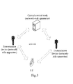
Fig.3 is an architectural diagram of a communication system in an embodiment of the invention; -
Fig.4 is a schematic functional structural diagram of a user equipment in an embodiment of the invention; -
Fig.5 is a schematic functional structural diagram of a network-side apparatus in an embodiment of the invention; -
Fig.6 is a flow chart of a user equipment reporting a CQI to a network-side apparatus in an embodiment of the invention; and -
Fig.7 is a flow chart of a network-side apparatus processing a CQI reported from a user equipment in an embodiment of the invention - In the technology of multipoint coordinated transmission, in order to enable the network side to have accurate knowledge of interference to which a user equipment is subjected to thereby correctly perform resource allocation and scheduling, in an embodiment of the invention, the user equipment needs to measure initial CQIs for respective devices in a measurement set, to report the initial CQIs of the respective devices to a network-side apparatus and to transmit channel matrix reference information to the network-side apparatus so that the network-side apparatus calculates a target CQI of the user equipment based upon the received initial CQIs of the respective devices and channel matrix reference information.
- The measurement set includes a first device transmitting service data to the user equipment and at least one second device participating in multipoint coordinated transmission to the user equipment; and the first device and the second device can be base stations of different cells or can be base stations of the same cell.
- In this embodiment, the network-side apparatus can be the first device in the measurement set or can be any one or more devices in the measurement set (which can be the first device or the second device) or can be a central control node connected with all the devices in the measurement set.
- Preferred implementations of the invention will be detailed below with reference to the drawings.
- Referring to
Fig.3 , in an embodiment of the invention, a CoMP-enabled communication system (which can be a TDD system or an FDD system) includes a user equipment and several transmission devices, and there is a multipoint coordinated transmission relationship (which can be either a coordinated scheduling relationship or a joint transmission relationship) between these transmission devices, where one of the transmission devices, i.e., the first device, transmits service data to the user equipment, and the other transmission devices, i.e., the second devices, also participate in multipoint coordinated transmission to the user equipment; and a measurement set for the user equipment is composed of the first device and the at least one second devices, and during network registration of the user equipment, the measurement set is notified in advance from the network side to the user equipment and stored in the user equipment, and the user equipment needs to measure channel information for each device in the measurement set so that the network side accurately estimates interference to which the user equipment is subjected. - The user equipment is configured to determine a measurement set used by the user equipment, the measurement set including the first device transmitting service data to the user equipment and the at least one second device participating in multipoint coordinated transmission to the user equipment, to receive a measurement reference signal transmitted from each device in the measurement set respectively, to measure an initial CQI of each device respectively based upon the measurement reference signal transmitted from the corresponding device, to transmit the derived initial CQIs of the respective devices to a network-side apparatus, and to transmit also channel matrix reference information to the network-side apparatus so that the network-side apparatus calculates a target CQI of the user equipment based upon the received initial CQIs of the respective devices and channel matrix reference information; and
- The network-side apparatus is configured to receive the initial CQIs, of the respective devices in the measurement set, transmitted from the user equipment, to receive the channel matrix reference information originating from the user equipment, and to calculate the target CQI of the user equipment based upon the received initial CQIs of the respective devices and channel matrix reference information.
- Referring to
Fig.4 , in an embodiment of the invention, a user equipment includes a determiningunit 40, a receivingunit 41, a measuringunit 42 and a transmittingunit 43, where: - The determining
unit 40 is configured to determine a measurement set used by the user equipment, where the measurement set includes a first device transmitting service data to the user equipment and at least one second device participating in multipoint coordinated transmission to the user equipment; the receivingunit 41 is configured to receive a measurement reference signal transmitted from each device in the measurement set respectively; - The measuring
unit 42 is configured to measure an initial CQI of each device respectively based upon the measurement reference signal transmitted from the corresponding device; and - The transmitting
unit 43 is configured to transmit the derived initial CQIs of the respective devices to the network-side apparatus and to transmit channel matrix reference information to the network-side apparatus so that the network-side apparatus calculates a target CQI of the user equipment based upon the received initial CQIs of the respective devices and channel matrix reference information. - Referring to
Fig.5 , in an embodiment of the invention, the network-side apparatus includes a communicatingunit 50 and aprocessing unit 51, where: - The communicating
unit 50 is configured to receive initial CQIs, of respective devices in a measurement set, transmitted from a user equipment, where the measurement set includes a first device transmitting service data to the user equipment and at least one second device participating in multipoint coordinated transmission to the user equipment, and to receive channel matrix reference information originating from the user equipment; and - The
processing unit 51 is configured to calculate a target CQI of the user equipment based upon the received initial CQIs of the respective devices and channel matrix reference information. - Based upon the foregoing technical solution, referring to
Fig.6 , in an embodiment of the invention, a user equipment reports a CQI to the network side in the following detailed flow: - Step 600: The user equipment determines a measurement set used by the user equipment, the measurement set including a first device transmitting service data to the user equipment and at least one second device participating in multipoint coordinated transmission to the user equipment.
- The measurement set used by the user equipment can be transmitted to the user equipment after being configured by a base station, and the user equipment determines the measurement set according to an indicator of the base station, for example, the base station notifies a particular measurement set in downlink signaling; or the measurement set can be configured by the user equipment itself in a pattern prescribed with the network side.
- Step 610: The user equipment receives a measurement reference signal transmitted from each device in the measurement set respectively and measures an initial CQI of each device respectively based upon the measurement reference signal transmitted from the corresponding device.
- In this embodiment, the measurement reference signal, transmitted from each device, received by the user equipment includes a CRS and/or a CSI-RS transmitted from the corresponding device.
- The user equipment measures the initial CQI of any device based upon the measurement reference signal transmitted from the device by firstly deriving a channel matrix of the device to the user equipment on respective sub-carriers based upon the measurement reference signal transmitted from the device and then calculating the initial CQI of the device in Formula 1:

- Where
γ qi is the initial CQI of the i-th device in the measurement set of the user equipment q; - Q(·) is a quantization function;
- S is a set of sub-carriers, where S includes sub-carriers in a section of time-frequency resource block, which can be a Physical Resource Block (PRB), a sub-band (including several consecutive PRBs) or the entire bandwidth of a system;
- f(·) is a mapping function to map {γqi (k)} k∈S to a value representing an average channel quality on all the sub-carriers in S, where f(·) can be linear averaging,

- γqi (k) is the initial CQI of the i-th device in the measurement set of the user equipment q on a sub-carrier k, where


- Step 620: The user equipment transmits the derived initial CQIs of the respective devices to the network-side apparatus and transmits channel matrix reference information to the network-side apparatus so that the network-side apparatus calculates a target CQI of the user equipment (that is, a CQI from which the network side finally performs resource scheduling and MCS selection for the user equipment) based upon the received initial CQIs of the respective devices and channel matrix reference information.
- The target CQI of the user equipment can be calculated in the first device or can be calculated in any one or more devices in the measurement set or can be calculated in a central control node connected with all the devices in the measurement set, that is, the network-side apparatus can be the first device, or any one or more devices in the measurement set, or the central control node.
- In this embodiment, the user equipment transmitting the derived initial CQIs of the respective devices to the network-side apparatus refers to that the user equipment transmitting the derived initial CQIs of the respective devices to the first device on an uplink channel or to the any one or more devices in the measurement set (which can include either the first device or the second device) or to the central control node connected with all the devices in the measurement set.
- In the process of the
step 620, the user equipment can transmit the channel matrix reference information to the network-side apparatus in (including but not limited to) the following two approaches: - In a first approach, the user equipment transmits an SRS after transmitting the derived initial CQIs of the respective devices to the network-side apparatus so that each device in the measurement set derives an uplink channel matrix of the user equipment to the corresponding device based upon the received SRS and derives a corresponding downlink channel matrix based upon channel reciprocity and then transmits its own derived downlink channel matrix to the network-side apparatus as the channel matrix reference information.
- In a second approach, the user equipment transmits channel matrices, derived respectively based upon a downlink reference symbol of each device in the measurement set, to the network-side apparatus as the channel matrix reference information after transmitting the derived initial CQIs of the respective devices to the network-side apparatus. At this time the user equipment needs not to transmit an SRS.
- For example, after an SRS transmitted from the user equipment is received by a base station in a specific device in the measurement set, the base station calculates an uplink channel matrix of the user equipment to the device served by the base station according to the received SRS and derives a downlink channel matrix Ĥqi (k) based upon channel reciprocity, and since the user equipment is different in transmission power from the base station and uplink and downlink radio frequency links doe not match, Ĥqi (k) may be different from real downlink channel information Hqi (k) by a constant, i.e., Ĥqi (k) = αHqi (k). In this embodiment, Ĥqi (k) can alternatively be a channel matrix derived by the base station from a feedback by the user equipment, and at this time, the user equipment needs not to transmit an SRS signal.
- Based upon the foregoing embodiment, referring to
Fig.7 , in an embodiment of the invention, a network-side apparatus processes a CQI reported from a user equipment in the following detailed flow: - Step 700: The network-side apparatus receives initial CQIs, of respective devices in a measurement set, transmitted from the user equipment, where the measurement set includes a serving device of the user equipment and a coordinating device participating in multipoint coordinated transmission to the user equipment.
- Alike the network-side apparatus can be the first device in the measurement set or can be any one or more devices in the measurement set or can be a central control node connected with all the devices in the measurement set. If it is more than one base station, then the respective base stations operate under the same principle.
- Step 710: The network side receives channel matrix reference information originating from the user equipment and calculates a target CQI of the user equipment based upon the received initial CQIs of the respective devices and channel matrix reference information.
- In this embodiment, in the process of the
step 710, the network-side apparatus can also receive channel matrix reference information originating from the user equipment in (including but not limited to) the following two approaches: - In a first approach, each device in the measurement set derives a corresponding uplink channel matrix respectively based upon an SRS received from the user equipment and derives a corresponding downlink channel matrix respectively based upon channel reciprocity, and the network-side apparatus receives the downlink channel matrix transmitted from each device respectively and takes the respective downlink channel matrices as the channel matrix reference information.
- In a second approach, the network-side apparatus receives channel matrices, transmitted from the user equipment, derived respectively based upon a downlink reference symbol of each device in the measurement set and takes the respective channel matrices as the channel matrix reference information.
- In this embodiment, the network-side apparatus calculates a target CQI of the user equipment based upon the received initial CQIs of the respective devices and channel matrix reference information particularly as follows: after scheduling is performed by the respective devices in the measurement set (scheduling here can be CoMP-based scheduling or single-device scheduling), the network-side apparatus firstly calculates target CQIs of the user equipment on respective sub-carriers and then maps the derived target CQIs on the respective sub-carriers to a unified value, where:
- The target CQI of the user equipment on any sub-carrier can be calculated in
Formula 2 particularly as follows:
Where: - γ̂q (k) is the target CQI of the user equipment q on a sub-carrier k;
- γ̂qi is the initial CQI of the i-th device in the measurement set of the user equipment q;
-
H qi (k) is a normalized channel matrix derived based upon Ĥqi (k), Ĥqi (k) = αHqi (k), and Hqi (k) is a channel matrix of the i-th device to the user equipment q on the sub-carrier k, -
H qi (k) can be derived based upon Ĥqi (k) variously, for example,
H qi (k) is derived by normalizing the average of ∥Ĥqi (k)∥ over a segment of bandwidth, and a repeated description thereof will be omitted here; - Ui is a set of user equipments finally scheduled by the i-th device in the measurement set;
- wq is a pre-coding weight of the user equipment q;
- NR,q is the number of receiving antennas of the user equipment q;
- A is the measurement set;
-
γ qp is the initial CQI of the p-th device in the measurement set of the user equipment q, where p≠i; -
H qp (k) is a normalized channel matrix derived based upon Ĥqp (k), Ĥqp(k) = αHqp (k), and Hqp(k) is a channel matrix of the p-th device to the user equipment q on the sub-carrier k, where p≠i; Up is a set of user equipments finally scheduled by the p-th device in the measurement set, where p≠i; and - wl is a pre-coding weight of a
user equipment 1. - Alternatively if the complexity of calculation is allowed, then the target CQI of the user equipment on any sub-carrier can be calculated in Formula 3:
- If the complexity of calculation is allowed, then the network-side apparatus can calculate a CQI output from a detector with the following assumed input-output model:


Where:- γ̂q (k) is the target CQI of the user equipment q on the sub-carrier k;
-
γ qi is the initial CQI of the i-th device in the measurement set of the user equipment q; - gq (k) is the linear detector of the user equipment q on the sub-carrier k;
- Hqi (k) is a normalized channel matrix derived based upon Ĥqi (k), Ĥqi (k) = αHqi (k), and Hqi (k) is a channel matrix of the i-th device to the user equipment q on the sub-carrier k;
- Ui is a set of user equipments finally scheduled by the i-th device in the measurement set;
- wq is a pre-coding weight of the user equipment q;
- A is the measurement set;
-
γ qp is the initial CQI of the p-th device in the measurement set of the user equipment q, where p≠i; -
H qp (k) is a normalized channel matrix derived based upon Ĥqp (k), Ĥqp (k) = αHqp (k), and Hqp (k) is a channel matrix of the p-th device to the user equipment q on the sub-carrier k, where p≠i; - Up is a set of user equipments finally scheduled by the p-th device in the measurement set, where p≠i;
- wl is a pre-coding weight of a
user equipment 1; and - w m is a pre-coding weight of a user equipment m.
- After the target CQIs of the user equipment on the respective sub-carriers are derived in any of the foregoing approaches, the derived target CQIs on the respective sub-carriers are mapped to the unified value in Formula 4 particularly as follows:

Where: - γq is the unified value to which the derived target CQIs on the respective sub-carriers are mapped;
- γ̂p (k) is the target CQI of the user equipment q on the sub-carrier k;
- f(·) is a mapping function which, for example, can be an EESM or another mapping function; and
- S is a set of sub-carriers, where S includes sub-carriers in a segment of bandwidth, which can be a PRB, a sub-band (including several consecutive PRBs) or the entire bandwidth of a system.
- Thus the network-side apparatus maps γ̂ q(k) of the respective sub-carriers to a single CQI value, and here the base station can determine for the user equipment an MCS and a frequency-domain resource for downlink transmission of data based upon the derived single CQI value.
- In the foregoing embodiments, scheduling by the respective devices in the measurement set can be coordinated scheduling or separate single-device scheduling, and for these scenarios, particularly the latter, the use of the technical solution according to the embodiments of the invention can improve their or its accuracy of CQI calculation and MCS selection to thereby improve the performance of the entire system.
- In summary, in the embodiments of the invention, the user equipment feeds the initial CQIs of the respective devices in the measurement set back to the base station in the network-side apparatus according to the measurement reference signals transmitted from the respective devices in the measurement set, and the network-side apparatus calculates the target CQI of the user equipment according to the initial CQIs of the respective devices fed back from the user equipment and the channel matrix reference information fed back from the user equipment, thereby addressing the problem of feeding back a CQI for multipoint coordinated transmission in the TDD system so that the network-side apparatus can derive the target CQI finally used for downlink transmission of data based upon the initial CQIs of the multiple devices fed back from the user equipment, and thus the network side can have accurate knowledge of interference to which the user equipment is subjected and further correctly perform user equipment scheduling, resource allocation and MCS selection to thereby effectively improve the throughout of the system in multipoint coordinated transmission and improve the performance of the system. The present embodiments will be equally applicable to the FDD system, and a repeated description thereof will be omitted here.
- Those skilled in the art shall appreciate that the embodiments of the invention can be embodied as a method, a system or a computer program product. Therefore the invention can be embodied in the form of an all-hardware embodiment, an all-software embodiment or an embodiment of software and hardware in combination. Furthermore the invention can be embodied in the form of a computer program product embodied in one or more computer useable storage mediums (including but not limited to a disk memory, a CD-ROM, an optical memory, etc.) in which computer useable program codes are contained.
- The invention has been described in a flow chart and/or a block diagram of the method, the device (system) and the computer program product according to the embodiments of the invention. It shall be appreciated that respective flows and/or blocks in the flow chart and/or the block diagram and combinations of the flows and/or the blocks in the flow chart and/or the block diagram can be embodied in computer program instructions. These computer program instructions can be loaded onto a general-purpose computer, a specific-purpose computer, an embedded processor or a processor of another programmable data processing device to produce a machine so that the instructions executed on the computer or the processor of the other programmable data processing device create means for performing the functions specified in the flow(s) of the flow chart and/or the block(s) of the block diagram.
- These computer program instructions can also be stored into a computer readable memory capable of directing the computer or the other programmable data processing device to operate in a specific manner so that the instructions stored in the computer readable memory create an article of manufacture including instruction means which perform the functions specified in the flow(s) of the flow chart and/or the block(s) of the block diagram.
- These computer program instructions can also be loaded onto the computer or the other programmable data processing device so that a series of operational steps are performed on the computer or the other programmable data processing device to create a computer implemented process so that the instructions executed on the computer or the other programmable device provide steps for performing the functions specified in the flow(s) of the flow chart and/or the block(s) of the block diagram.
- Although the preferred embodiments of the invention have been described, those skilled in the art benefiting from the underlying inventive concept can make additional modifications and variations to these embodiments. Therefore the appended claims are intended to be construed as encompassing the preferred embodiments and all the modifications and variations coming into the scope of the invention.
- Evidently those skilled in the art can make various modifications and variations to the invention without departing from the spirit and scope of the invention. Thus the invention is also intended to encompass these modifications and variations thereto so long as the modifications and variations come into the scope of the claims appended to the invention and their equivalents.
Claims (25)
- A method of reporting a Channel Quality Indicator, CQI, comprising:a user equipment determining a measurement set used by the user equipment, the measurement set comprising a first device transmitting service data to the user equipment and at least one second device participating in multipoint coordinated transmission to the user equipment;the user equipment receiving a measurement reference signal transmitted from each device in the measurement set respectively and measuring an initial CQI of each device respectively based upon the measurement reference signal transmitted from the corresponding device; andthe user equipment transmitting the derived initial CQIs of the respective devices to a network-side apparatus and transmitting channel matrix reference information to the network-side apparatus so that the network-side apparatus calculates a target CQI of the user equipment based upon the received initial CQIs of the respective devices and channel matrix reference information.
- The method according to claim 1, wherein the user equipment receiving a measurement reference signal transmitted from each device in the measurement set respectively comprises:the user equipment receiving a Cell-specific Reference Signal, CRS, and/or a Channel State Information-Reference Signal, CSI-RS, transmitted from each device in the measurement set respectively.
- The method according to claim 1 or 2, wherein the user equipment measuring the initial CQI of any device based upon the measurement reference signal transmitted from the device comprises:the user equipment deriving channel matrices of the any device to the user equipment on respective sub-carriers based upon the measurement reference signal transmitted from the any device; andthe user equipment calculating the initial CQI of the any device based upon the channel matrices of the any device to the user equipment on the respective sub-carriers in a formula of
 γ̂qi is an initial CQI of the i-th device in the measurement set of the user equipment q;Q(·) is a quantization function;S is a set of sub-carriers;f(·) is a mapping function to map {γqi (k)} k∈S to a value representing an average channel quality on all the sub-carriers in S; andγqi (k) is an initial CQI of the i-th device in the measurement set of the user equipment q on a sub-carrier k, wherein

- The method according to claim 3, wherein the user equipment transmitting the derived initial CQIs of the respective devices to the network-side apparatus comprises:the user equipment transmitting the derived initial CQIs of the respective devices to the first device or to any one or more devices in the measurement set or to a central control node connected with all devices in the measurement set.
- The method according to claim 3, wherein the user equipment transmitting channel matrix reference information to the network-side apparatus comprises:the user equipment transmitting an uplink Sounding Reference Signal, SRS, so that each device in the measurement set derives a corresponding uplink channel matrix respectively based upon the received SRS and derives a corresponding downlink channel matrix respectively based upon channel reciprocity and then transmits its own derived downlink channel matrix to the network-side apparatus as the channel matrix reference information; orthe user equipment transmitting channel matrices, derived respectively based upon downlink reference symbols of respective devices in the measurement set, to the network-side apparatus as the channel matrix reference information.
- A method of processing a Channel Quality Indicator, CQI, comprising:a network-side apparatus receiving initial CQIs, of respective devices in a measurement set, transmitted from a user equipment, the measurement set comprising a first device transmitting service data to the user equipment and at least one second device participating in multipoint coordinated transmission to the user equipment; andthe network-side apparatus receiving channel matrix reference information originating from the user equipment and calculating a target CQI of the user equipment based upon the received initial CQIs of the respective devices and channel matrix reference information.
- The method according to claim 6, wherein the network-side apparatus is the first device of the user equipment or any one or more devices in the measurement set or a central control node connected with all devices in the measurement set.
- The method according to claim 6, wherein the network-side apparatus receiving channel matrix reference information originating from the user equipment comprises:each device in the measurement set deriving a corresponding uplink channel matrix respectively based upon an SRS received from the user equipment and deriving a corresponding downlink channel matrix respectively based upon channel reciprocity, and the network-side apparatus receiving the downlink channel matrix transmitted from the each device respectively and taking the respective downlink channel matrices as the channel matrix reference information; orthe network-side apparatus receiving a channel matrix, transmitted from the user equipment, derived respectively based upon a downlink reference symbol of each device in the measurement set and taking the respective channel matrices as the channel matrix reference information.
- The method according to claim 6, 7 or 8, wherein the network-side apparatus calculating a target CQI of the user equipment based upon the received initial CQIs of the respective devices and channel matrix reference information comprises:after scheduling is performed by the respective devices in the measurement set, the network-side apparatus calculating target CQIs of the user equipment on respective sub-carriers; andthe network-side apparatus mapping the derived target CQIs on the respective sub-carriers to a unified value.
- The method according to claim 9, wherein the network-side apparatus calculates the target CQI of the user equipment on any sub-carrier in a formula of
 γ̂q (k) is a target CQI of the user equipment q on a sub-carrier k;
γ qi is an initial CQI of the i-th device in the measurement set of the user equipment q;H qi (k) is a normalized channel matrix derived based upon Ĥqi (k), Ĥqi (k) = αHqi (k), and Hqi (k) is a channel matrix of the i-th device to the user equipment q on the sub-carrier k;Ui is a set of user equipments finally scheduled by the i-th device in the measurement set;wq is a pre-coding weight of the user equipment q;NR,q is the number of receiving antennas of the user equipment q;A is the measurement set;γ qp is an initial CQI of the p-th device in the measurement set of the user equipment q, wherein p≠i;H qp(k) is a normalized channel matrix derived based upon Ĥqp (k), Ĥqp(k) = αHqp (k), and Hqp(k) is a channel matrix of the p-th device to the user equipment q on the sub-carrier k, wherein p≠i;Up is a set of user equipments finally scheduled by the p-th device in the measurement set, wherein p≠i; andwl is a pre-coding weight of a user equipment 1. - The method according to claim 9, wherein the network-side apparatus calculates the target CQI of the user equipment on any sub-carrier in a formula of
 γ̂q (k) is a target CQI of the user equipment q on a sub-carrier k;
γ qi is an initial CQI of the i-th device in the measurement set of the user equipment q;gq (k) is a linear detector of the user equipment q on the sub-carrier k;Hqi (k) is a normalized channel matrix derived based upon Ĥ qi(k), Ĥqi (k) = αHqi (k), and Hqi (k) is a channel matrix of the i-th device to the user equipment q on the sub-carrier k;Ui is a set of user equipments finally scheduled by the i-th device in the measurement set;wq is a pre-coding weight of the user equipment q;A is the measurement set;γ qp is an initial CQI of the p-th device in the measurement set of the user equipment q, wherein p≠i;H qp(k) is a normalized channel matrix derived based upon Ĥqp (k), Ĥqp(k) = αHqp (k), and Hqp(k) is a channel matrix of the p-th device to the user equipment q on the sub-carrier k, wherein p≠i;Up is a set of user equipments finally scheduled by the p-th device in the measurement set, wherein p≠i;wl is a pre-coding weight of a user equipment 1; andw m is a pre-coding weight of a user equipment m. - The method according to claim 9, wherein the network-side apparatus maps the derived target CQIs on the respective sub-carriers to the unified value in a formula of γq = f({γ̂q (k)} k∈S), wherein γq is the unified value to which the derived target CQIs on the respective sub-carriers are mapped; γ̂q (k) is a target CQI of the user equipment q on a sub-carrier k; f(·) is a mapping function; and S is a set of sub-carriers.
- An apparatus for reporting a Channel Quality Indicator, CQI, comprising:a determining unit configured to determine a measurement set used by the apparatus, the measurement set comprising a first device transmitting service data to the apparatus and at least one second device participating in multipoint coordinated transmission to the apparatus;a receiving unit configured to receive a measurement reference signal transmitted from each device in the measurement set respectively;a measuring unit configured to measure an initial CQI of each device respectively based upon the measurement reference signal transmitted from the corresponding device; anda transmitting unit configured to transmit the derived initial CQIs of the respective devices to a network-side apparatus and to transmit channel matrix reference information to the network-side apparatus so that the network-side apparatus calculates a target CQI of the apparatus based upon the received initial CQIs of the respective devices and channel matrix reference information.
- The apparatus according to claim 13, wherein the receiving unit receiving a measurement reference signal transmitted from each device in the measurement set respectively comprises:the receiving unit receiving a Cell-specific Reference Signal, CRS, and/or a Channel State Information-Reference Signal, CSI-RS, transmitted from each device in the measurement set respectively.
- The apparatus according to claim 13 or 14, wherein the measuring unit measuring the initial CQI of any device based upon the measurement reference signal transmitted from the device comprises:the measuring unit deriving channel matrices of the any device to the apparatus on respective sub-carriers based upon the measurement reference signal transmitted from the any device; andthe measuring unit calculating the initial CQI of the any device based upon the channel matrices of the any device to the apparatus on the respective sub-carriers in a formula of
γ qi = Q(f({γqi (k)) k∈S)), wherein:γ qi is an initial CQI of the i-th device in the measurement set of the reporting apparatus q;Q(·) is a quantization function;S is a set of sub-carriers;f(·) is a mapping function to map {γqi (k)} k∈S to a value representing an average channel quality on all the sub-carriers in S; andγqi (k) is an initial CQI of the i-th device in the measurement set of the reporting apparatus q on a sub-carrier k, wherein

- The apparatus according to claim 15, wherein the transmitting unit transmitting the derived initial CQIs of the respective devices to the network-side apparatus comprises:the transmitting unit transmitting the derived initial CQIs of the respective devices to the first device or to any one or more devices in the measurement set or to a central control node connected with all devices in the measurement set.
- The apparatus according to claim 15, wherein the transmitting unit transmitting channel matrix reference information to the network-side apparatus comprises:the transmitting unit transmitting an uplink Sounding Reference Signal, SRS, so that each device in the measurement set derives a corresponding uplink channel matrix respectively based upon the received SRS and derives a corresponding downlink channel matrix respectively based upon channel reciprocity and then transmits its own derived downlink channel matrix to the network-side apparatus as the channel matrix reference information; orthe transmitting unit transmitting a channel matrix, derived respectively based upon a downlink reference symbol of each device in the measurement set, to the network-side apparatus as the channel matrix reference information.
- An apparatus for processing a Channel Quality Indicator, CQI, comprising:a communicating unit configured to receive initial CQIs, of respective devices in a measurement set, transmitted from a user equipment and to receive channel matrix reference information originating from the user equipment, the measurement set comprising a first device transmitting service data to the user equipment and at least one second device participating in multipoint coordinated transmission to the user equipment; anda processing unit configured to calculate a target CQI of the user equipment based upon the received initial CQIs of the respective devices and channel matrix reference information.
- The apparatus according to claim 18, wherein the apparatus is the first device transmitting service data to the user equipment or any one or more device base stations in the measurement set or a central control node connected with all devices in the measurement set.
- The apparatus according to claim 18, wherein the communicating unit receiving channel matrix reference information originating from the user equipment comprises:each device in the measurement set deriving a corresponding uplink channel matrix respectively based upon an SRS received from the user equipment and deriving a corresponding downlink channel matrix respectively based upon channel reciprocity, and the communicating unit receiving the downlink channel matrix transmitted from the each device respectively and taking the respective downlink channel matrices as the channel matrix reference information; orthe communicating unit receiving a channel matrix, transmitted from the user equipment, derived respectively based upon a downlink reference symbol of each device in the measurement set and taking the respective channel matrices as the channel matrix reference information.
- The apparatus according to claim 18, 19 or 20, wherein the processing unit calculating a target CQI of the user equipment based upon the received initial CQIs of the respective devices and channel matrix reference information comprises:after scheduling is performed by the respective devices in the measurement set, the processing unit calculating target CQIs of the user equipment on respective sub-carriers; andthe processing unit mapping the derived target CQIs on the respective sub-carriers to a unified value.
- The apparatus according to claim 21, wherein the processing unit calculates the target CQI of the user equipment on any sub-carrier in a formula of
 γ̂q (k) is a target CQI of the user equipment q on a sub-carrier k;
γ qi is an initial CQI of the i-th device in the measurement set of the user equipment q;H qi (k) is a normalized channel matrix derived based upon Ĥqi (k), Ĥqi (k) = αHqi (k), and Hqi (k) is a channel matrix of the i-th device to the user equipment q on the sub-carrier k;Ui is a set of user equipments finally scheduled by the i-th device in the measurement set;Ni is the number of user equipments finally scheduled by the i-th device in the measurement set;wq is a pre-coding weight of the user equipment q;NR,q is the number of receiving antennas of the user equipment q;A is the measurement set;γ qp is an initial CQI of the p-th device in the measurement set of the user equipment q, wherein p≠i;H qp(k) is a normalized channel matrix derived based upon Ĥqp (k), Ĥqp(k) = αHqp (k), and Hqp(k) is a channel matrix of the p-th device to the user equipment q on the sub-carrier k, wherein p≠i;Up is a set of user equipments finally scheduled by the p-th device in the measurement set, wherein p≠i; andwl is a pre-coding weight of a user equipment 1. - The apparatus according to claim 21, wherein the processing unit calculates the target CQI of the user equipment on any sub-carrier in a formula of
 γ̂q (k) is a target CQI of the user equipment q on a sub-carrier k;
γ qi is an initial CQI of the i-th device in the measurement set of the user equipment q;gq (k) is a linear detector of the user equipment q on the sub-carrier k;Hqi (k) is a normalized channel matrix derived based upon Ĥqi (k), Ĥqi (k) = αHqi (k), and Hqi (k) is a channel matrix of the i-th device to the user equipment q on the sub-carrier k;Ui is a set of user equipments finally scheduled by the i-th device in the measurement set;wq is a pre-coding weight of the user equipment q;A is the measurement set;γ qp is an initial CQI of the p-th device in the measurement set of the user equipment q, wherein p≠i;H qp(k) is a normalized channel matrix derived based upon Ĥqp (k), Ĥqp(k) = αHqp (k), and Hqp(k) is a channel matrix of the p-th device to the user equipment q on the sub-carrier k, wherein p≠i;Up is a set of user equipments finally scheduled by the p-th device in the measurement set, wherein p≠i;wl is a pre-coding weight of a user equipment 1; andw m is a pre-coding weight of a user equipment m. - The apparatus according to claim 21, wherein the processing unit maps the derived target CQIs on the respective sub-carriers to the unified value in a formula of γq = f({γ̂q (k)} k ∈S), wherein γq is the unified value to which the derived target CQIs on the respective sub-carriers are mapped; γ̂q (k) is a target CQI of the user equipment q on a sub-carrier k; f(·) is a mapping function; and S is a set of sub-carriers.
- A system for reporting and processing a Channel Quality Indicator, CQI, comprising:a user equipment configured to determine a measurement set used by the user equipment, the measurement set comprising a first device transmitting service data to the user equipment and at least one second device participating in multipoint coordinated transmission to the user equipment; and to receive a measurement reference signal transmitted from each device in the measurement set respectively, to measure an initial CQI of each device respectively based upon the measurement reference signal transmitted from the corresponding device, to transmit the derived initial CQIs of the respective devices to a network-side apparatus, and to transmit channel matrix reference information to the network-side apparatus so that the network-side apparatus calculates a target CQI of the user equipment based upon the received initial CQIs of the respective devices and channel matrix reference information; andthe network-side apparatus configured to receive the initial CQIs, of the respective devices in the measurement set, transmitted from the user equipment, to receive the channel matrix reference information originating from the user equipment and to calculate the target CQI of the user equipment based upon the received initial CQIs of the respective devices and channel matrix reference information.
Applications Claiming Priority (2)
| Application Number | Priority Date | Filing Date | Title |
|---|---|---|---|
| CN201110102148.2A CN102149130B (en) | 2011-04-22 | 2011-04-22 | Method, device and system for reporting channel quality indicator |
| PCT/CN2012/073438 WO2012142913A1 (en) | 2011-04-22 | 2012-03-31 | Method, device, and system for reporting channel quality indicator |
Publications (3)
| Publication Number | Publication Date |
|---|---|
| EP2701425A1 true EP2701425A1 (en) | 2014-02-26 |
| EP2701425A4 EP2701425A4 (en) | 2014-09-17 |
| EP2701425B1 EP2701425B1 (en) | 2020-01-01 |
Family
ID=44423063
Family Applications (1)
| Application Number | Title | Priority Date | Filing Date |
|---|---|---|---|
| EP12774811.9A Active EP2701425B1 (en) | 2011-04-22 | 2012-03-31 | Method, device, and system for reporting channel quality indicator |
Country Status (6)
| Country | Link |
|---|---|
| US (1) | US9252932B2 (en) |
| EP (1) | EP2701425B1 (en) |
| JP (1) | JP5681833B2 (en) |
| KR (1) | KR101548577B1 (en) |
| CN (1) | CN102149130B (en) |
| WO (1) | WO2012142913A1 (en) |
Cited By (2)
| Publication number | Priority date | Publication date | Assignee | Title |
|---|---|---|---|---|
| EP2779508A4 (en) * | 2011-12-14 | 2015-05-06 | Huawei Tech Co Ltd | METHOD AND DEVICE FOR OBTAINING CHANNEL STATUS INFORMATION |
| EP2993934A4 (en) * | 2013-06-04 | 2016-06-22 | Huawei Tech Co Ltd | METHOD AND DEVICE FOR DATA TRANSMISSION AND USER EQUIPMENT |
Families Citing this family (37)
| Publication number | Priority date | Publication date | Assignee | Title |
|---|---|---|---|---|
| CN102149130B (en) * | 2011-04-22 | 2014-01-01 | 电信科学技术研究院 | Method, device and system for reporting channel quality indicator |
| CN102291740B (en) * | 2011-08-16 | 2014-05-21 | 电信科学技术研究院 | Method and device for transmitting channel quality indication (CQI) |
| CN102237968B (en) * | 2011-08-16 | 2013-11-06 | 电信科学技术研究院 | Channel state information transmission method and device |
| CN102291839B (en) * | 2011-08-16 | 2014-07-09 | 电信科学技术研究院 | Method and device for transmitting CQI (channel quality indicator) information |
| US8797966B2 (en) * | 2011-09-23 | 2014-08-05 | Ofinno Technologies, Llc | Channel state information transmission |
| CN102368697B (en) * | 2011-09-30 | 2018-04-03 | 中兴通讯股份有限公司 | Interferometry signals, interferometry and feedback method and its device |
| US8885569B2 (en) | 2011-12-19 | 2014-11-11 | Ofinno Technologies, Llc | Beamforming signaling in a wireless network |
| US8953478B2 (en) * | 2012-01-27 | 2015-02-10 | Intel Corporation | Evolved node B and method for coherent coordinated multipoint transmission with per CSI-RS feedback |
| US9204317B2 (en) | 2012-05-11 | 2015-12-01 | Telefonaktiebolaget L M Ericsson (Publ) | Methods and arrangements for CSI reporting |
| US9407343B2 (en) * | 2012-08-31 | 2016-08-02 | Google Technology Holdings LLC | Method and apparatus for mitigating downlink interference |
| CN103718635B (en) * | 2013-03-14 | 2018-02-02 | 华为技术有限公司 | Method and base station for scheduling user equipment |
| JP6141510B2 (en) * | 2013-04-08 | 2017-06-07 | エルジー エレクトロニクス インコーポレイティド | Channel state information reporting method and apparatus therefor for split beamforming in a wireless communication system |
| CN105210315B (en) * | 2013-05-07 | 2017-12-19 | Lg电子株式会社 | The method and its equipment of measurement are performed in a wireless communication system |
| KR101492542B1 (en) | 2013-08-30 | 2015-02-23 | 에스케이텔레콤 주식회사 | An apparatus and method for allocating wireless resource of telecommunication system using carrier aggregation |
| EP3094128A4 (en) * | 2014-01-29 | 2017-01-11 | Huawei Technologies Co., Ltd. | Method, apparatus and system for coordinated communication |
| WO2015147524A1 (en) * | 2014-03-25 | 2015-10-01 | 한국전자통신연구원 | Terminal, base station, and operation method thereof in distributed antenna system |
| EP3217714B1 (en) | 2014-11-07 | 2019-09-25 | Huawei Technologies Co., Ltd. | Wireless network coverage enhancement method, apparatus and system |
| US20160226647A1 (en) * | 2015-01-30 | 2016-08-04 | Nokia Solutions And Networks Oy | Reference precoding vectors for multiple rank indications for channel quality indication (cqi) reporting in a wireless |
| CN106817720B (en) * | 2015-11-27 | 2019-07-02 | 中兴通讯股份有限公司 | A method and device for acquiring channel information |
| US10602507B2 (en) * | 2016-09-29 | 2020-03-24 | At&T Intellectual Property I, L.P. | Facilitating uplink communication waveform selection |
| US10644924B2 (en) | 2016-09-29 | 2020-05-05 | At&T Intellectual Property I, L.P. | Facilitating a two-stage downlink control channel in a wireless communication system |
| US10206232B2 (en) | 2016-09-29 | 2019-02-12 | At&T Intellectual Property I, L.P. | Initial access and radio resource management for integrated access and backhaul (IAB) wireless networks |
| CN107888268B (en) * | 2016-09-30 | 2023-03-31 | 华为技术有限公司 | CSI measuring method and device |
| CN107979402B (en) * | 2016-10-25 | 2020-09-08 | 华为技术有限公司 | Method and device for measuring channel state information |
| CN107070581B (en) * | 2016-12-29 | 2019-10-25 | 上海华为技术有限公司 | A kind of interference elimination method and base station |
| CN108282807B (en) * | 2017-01-06 | 2023-11-10 | 华为技术有限公司 | Method and device for measuring, selecting and reporting channel quality information |
| US11246051B2 (en) | 2017-08-04 | 2022-02-08 | Lg Electronics Inc. | Method and apparatus for interference measurement in wireless communication system |
| CN111684741B (en) * | 2018-02-09 | 2022-07-22 | 中兴通讯股份有限公司 | Method and apparatus for multi-layer data transmission |
| CN110247690B (en) * | 2018-03-09 | 2021-10-01 | 华为技术有限公司 | Method and apparatus for informing channel quality |
| CN111278005B (en) * | 2019-01-22 | 2021-09-24 | 维沃移动通信有限公司 | Capability information reporting method, precoding matrix indication feedback method and related equipment |
| CN111953457B (en) * | 2019-05-14 | 2022-06-21 | 上海朗帛通信技术有限公司 | Method and apparatus in a node used for wireless communication |
| CN112020092B (en) * | 2019-05-31 | 2022-05-24 | 华为技术有限公司 | Channel information acquisition method and device |
| TWI768770B (en) * | 2021-03-16 | 2022-06-21 | 瑞昱半導體股份有限公司 | Wireless communication device and method |
| CN116017345B (en) * | 2021-10-21 | 2025-10-21 | 宸芯科技股份有限公司 | Unicast communication method, device, computer equipment and medium in vehicle network |
| CN117375781B (en) * | 2022-06-30 | 2026-01-27 | 华为技术有限公司 | Indication method and device of reference signal |
| CN118265043A (en) * | 2022-12-26 | 2024-06-28 | 维沃移动通信有限公司 | Performance monitoring method, terminal and network side equipment of AI unit |
| WO2026007704A1 (en) * | 2024-07-04 | 2026-01-08 | Mediatek Inc. | Full duplex device-to-device communication csi and pmi signaling framework based on ue measurement and feedback |
Family Cites Families (15)
| Publication number | Priority date | Publication date | Assignee | Title |
|---|---|---|---|---|
| CN101127747B (en) * | 2006-08-14 | 2010-09-08 | 大唐移动通信设备有限公司 | A method and system for frequency domain scheduling in time division duplex multiplexing system |
| EP2070229B1 (en) * | 2006-10-05 | 2016-03-09 | Telefonaktiebolaget LM Ericsson (publ) | Method for predicting channel quality indicator (cqi) values. |
| CN101557249B (en) * | 2008-04-07 | 2012-11-07 | 上海贝尔阿尔卡特股份有限公司 | Method and device for controlling cooperative transmission of downlink signal in wireless communication system |
| CN101686077B (en) * | 2008-09-26 | 2012-10-03 | 电信科学技术研究院 | Method and device for multi-point synergetic transmission |
| WO2010080632A2 (en) * | 2008-12-18 | 2010-07-15 | Nec Laboratories America, Inc. | Mu-mimo-ofdma systems and methods for servicing overlapping co-scheduled users |
| CN101753186B (en) * | 2008-12-19 | 2013-04-03 | 电信科学技术研究院 | Channel quality information estimating method used for transmitting multi-flow beam forming data |
| CN101841847B (en) * | 2009-03-18 | 2013-03-13 | 电信科学技术研究院 | Feedback method, system and device for channel quality indication information |
| CN101854658B (en) * | 2009-03-31 | 2013-09-11 | 电信科学技术研究院 | Method and system for processing channel quality indication information |
| CN101854233B (en) | 2009-04-03 | 2013-01-23 | 电信科学技术研究院 | Method and equipment for processing channel quality indication information |
| US8711716B2 (en) * | 2009-06-19 | 2014-04-29 | Texas Instruments Incorporated | Multiple CQI feedback for cellular networks |
| CN101997587B (en) | 2009-08-14 | 2014-11-05 | 中兴通讯股份有限公司 | Method and device for determining channel quality indicator (CQI) value in coordinated multi-point transmission/reception (COMP) |
| KR20110019284A (en) * | 2009-08-19 | 2011-02-25 | 주식회사 팬택 | Method and apparatus for transmitting uplink wideband measurement signal in wireless communication system, method for estimating downlink channel using same |
| CN101997583B (en) * | 2009-08-21 | 2015-07-01 | 索尼株式会社 | Method and device for pairing uplink multi-user multi-input multi-output (MIMO) users supporting cooperation multi-point transmission |
| JP5210278B2 (en) | 2009-10-05 | 2013-06-12 | 株式会社エヌ・ティ・ティ・ドコモ | Radio base station apparatus, mobile terminal apparatus and radio communication method |
| CN102149130B (en) | 2011-04-22 | 2014-01-01 | 电信科学技术研究院 | Method, device and system for reporting channel quality indicator |
-
2011
- 2011-04-22 CN CN201110102148.2A patent/CN102149130B/en active Active
-
2012
- 2012-03-31 EP EP12774811.9A patent/EP2701425B1/en active Active
- 2012-03-31 WO PCT/CN2012/073438 patent/WO2012142913A1/en not_active Ceased
- 2012-03-31 US US14/113,216 patent/US9252932B2/en active Active
- 2012-03-31 KR KR1020137030892A patent/KR101548577B1/en active Active
- 2012-03-31 JP JP2014505492A patent/JP5681833B2/en active Active
Cited By (3)
| Publication number | Priority date | Publication date | Assignee | Title |
|---|---|---|---|---|
| EP2779508A4 (en) * | 2011-12-14 | 2015-05-06 | Huawei Tech Co Ltd | METHOD AND DEVICE FOR OBTAINING CHANNEL STATUS INFORMATION |
| EP2993934A4 (en) * | 2013-06-04 | 2016-06-22 | Huawei Tech Co Ltd | METHOD AND DEVICE FOR DATA TRANSMISSION AND USER EQUIPMENT |
| US9980260B2 (en) | 2013-06-04 | 2018-05-22 | Huawei Technologies Co., Ltd. | Data transmission method and apparatus, and user equipment |
Also Published As
| Publication number | Publication date |
|---|---|
| KR20140009519A (en) | 2014-01-22 |
| CN102149130B (en) | 2014-01-01 |
| EP2701425A4 (en) | 2014-09-17 |
| CN102149130A (en) | 2011-08-10 |
| KR101548577B1 (en) | 2015-09-11 |
| JP5681833B2 (en) | 2015-03-11 |
| WO2012142913A1 (en) | 2012-10-26 |
| US20140056272A1 (en) | 2014-02-27 |
| EP2701425B1 (en) | 2020-01-01 |
| US9252932B2 (en) | 2016-02-02 |
| JP2014512770A (en) | 2014-05-22 |
Similar Documents
| Publication | Publication Date | Title |
|---|---|---|
| US9252932B2 (en) | Method, device, and system for reporting channel quality indicator | |
| EP2701423B1 (en) | Method and device for measuring interference in coordinated multipoint transmission | |
| EP3906624B1 (en) | Method and apparatus for interference measurement in wireless communication system | |
| US10454555B2 (en) | Channel state information feedback method and apparatus for 2-dimensional massive MIMO communication system | |
| EP3337053B1 (en) | Communication technique using csi-rs in mobile communication system | |
| EP2800290B1 (en) | Method and device for processing channel state information | |
| CN109155693B (en) | Low complexity multi-configuration CSI reporting | |
| EP2648445B1 (en) | Method and device for reporting channel state | |
| CN105991231B (en) | Method and device for obtaining channel state information CSI | |
| US20250125843A1 (en) | Methods and apparatuses for port index signaling for non-precoder matrix indicator (pmi) channel state information (csi) feedback | |
| EP3565154A1 (en) | Configuration of coordinated multipoint transmission hypotheses for channel state information reporting | |
| CN102474408B (en) | Method for operating a radio station in a mobile network | |
| CN102036393A (en) | Method and equipment for determining multi-cell channel information | |
| RU2012130026A (en) | SYSTEMS AND METHODS FOR TRANSMISSION OF INFORMATION ON QUALITY OF A CHANNEL IN WIRELESS COMMUNICATION SYSTEMS | |
| CN103580779B (en) | Channel quality instruction information reporting and determining method and equipment | |
| CN106888062B (en) | CQI estimation and SINR determination method and related equipment | |
| KR20170020270A (en) | Method and apparatus of tranceiving a reference signal in a communication system | |
| CN103814598A (en) | Channel quality information estimation method and device, base station and network center processing equipment | |
| US9615280B2 (en) | Calculating and reporting channel characteristics | |
| US9119082B1 (en) | Reference signal design for interference measurement | |
| CN102291839A (en) | Method and device for transmitting CQI (channel quality indicator) information | |
| US9048970B1 (en) | Feedback for cooperative multipoint transmission systems | |
| CN111886915A (en) | Base station, method, program, and recording medium |
Legal Events
| Date | Code | Title | Description |
|---|---|---|---|
| PUAI | Public reference made under article 153(3) epc to a published international application that has entered the european phase |
Free format text: ORIGINAL CODE: 0009012 |
|
| 17P | Request for examination filed |
Effective date: 20131121 |
|
| AK | Designated contracting states |
Kind code of ref document: A1 Designated state(s): AL AT BE BG CH CY CZ DE DK EE ES FI FR GB GR HR HU IE IS IT LI LT LU LV MC MK MT NL NO PL PT RO RS SE SI SK SM TR |
|
| DAX | Request for extension of the european patent (deleted) | ||
| A4 | Supplementary search report drawn up and despatched |
Effective date: 20140814 |
|
| RIC1 | Information provided on ipc code assigned before grant |
Ipc: H04W 24/10 20090101AFI20140808BHEP |
|
| STAA | Information on the status of an ep patent application or granted ep patent |
Free format text: STATUS: EXAMINATION IS IN PROGRESS |
|
| 17Q | First examination report despatched |
Effective date: 20180404 |
|
| GRAP | Despatch of communication of intention to grant a patent |
Free format text: ORIGINAL CODE: EPIDOSNIGR1 |
|
| STAA | Information on the status of an ep patent application or granted ep patent |
Free format text: STATUS: GRANT OF PATENT IS INTENDED |
|
| INTG | Intention to grant announced |
Effective date: 20190724 |
|
| GRAS | Grant fee paid |
Free format text: ORIGINAL CODE: EPIDOSNIGR3 |
|
| GRAA | (expected) grant |
Free format text: ORIGINAL CODE: 0009210 |
|
| STAA | Information on the status of an ep patent application or granted ep patent |
Free format text: STATUS: THE PATENT HAS BEEN GRANTED |
|
| AK | Designated contracting states |
Kind code of ref document: B1 Designated state(s): AL AT BE BG CH CY CZ DE DK EE ES FI FR GB GR HR HU IE IS IT LI LT LU LV MC MK MT NL NO PL PT RO RS SE SI SK SM TR |
|
| REG | Reference to a national code |
Ref country code: GB Ref legal event code: FG4D |
|
| REG | Reference to a national code |
Ref country code: AT Ref legal event code: REF Ref document number: 1221385 Country of ref document: AT Kind code of ref document: T Effective date: 20200115 Ref country code: CH Ref legal event code: EP |
|
| REG | Reference to a national code |
Ref country code: DE Ref legal event code: R096 Ref document number: 602012066926 Country of ref document: DE |
|
| REG | Reference to a national code |
Ref country code: IE Ref legal event code: FG4D |
|
| REG | Reference to a national code |
Ref country code: NL Ref legal event code: MP Effective date: 20200101 |
|
| REG | Reference to a national code |
Ref country code: LT Ref legal event code: MG4D |
|
| PG25 | Lapsed in a contracting state [announced via postgrant information from national office to epo] |
Ref country code: NL Free format text: LAPSE BECAUSE OF FAILURE TO SUBMIT A TRANSLATION OF THE DESCRIPTION OR TO PAY THE FEE WITHIN THE PRESCRIBED TIME-LIMIT Effective date: 20200101 Ref country code: CZ Free format text: LAPSE BECAUSE OF FAILURE TO SUBMIT A TRANSLATION OF THE DESCRIPTION OR TO PAY THE FEE WITHIN THE PRESCRIBED TIME-LIMIT Effective date: 20200101 Ref country code: LT Free format text: LAPSE BECAUSE OF FAILURE TO SUBMIT A TRANSLATION OF THE DESCRIPTION OR TO PAY THE FEE WITHIN THE PRESCRIBED TIME-LIMIT Effective date: 20200101 Ref country code: PT Free format text: LAPSE BECAUSE OF FAILURE TO SUBMIT A TRANSLATION OF THE DESCRIPTION OR TO PAY THE FEE WITHIN THE PRESCRIBED TIME-LIMIT Effective date: 20200527 Ref country code: FI Free format text: LAPSE BECAUSE OF FAILURE TO SUBMIT A TRANSLATION OF THE DESCRIPTION OR TO PAY THE FEE WITHIN THE PRESCRIBED TIME-LIMIT Effective date: 20200101 Ref country code: NO Free format text: LAPSE BECAUSE OF FAILURE TO SUBMIT A TRANSLATION OF THE DESCRIPTION OR TO PAY THE FEE WITHIN THE PRESCRIBED TIME-LIMIT Effective date: 20200401 Ref country code: RS Free format text: LAPSE BECAUSE OF FAILURE TO SUBMIT A TRANSLATION OF THE DESCRIPTION OR TO PAY THE FEE WITHIN THE PRESCRIBED TIME-LIMIT Effective date: 20200101 |
|
| PG25 | Lapsed in a contracting state [announced via postgrant information from national office to epo] |
Ref country code: BG Free format text: LAPSE BECAUSE OF FAILURE TO SUBMIT A TRANSLATION OF THE DESCRIPTION OR TO PAY THE FEE WITHIN THE PRESCRIBED TIME-LIMIT Effective date: 20200401 Ref country code: GR Free format text: LAPSE BECAUSE OF FAILURE TO SUBMIT A TRANSLATION OF THE DESCRIPTION OR TO PAY THE FEE WITHIN THE PRESCRIBED TIME-LIMIT Effective date: 20200402 Ref country code: LV Free format text: LAPSE BECAUSE OF FAILURE TO SUBMIT A TRANSLATION OF THE DESCRIPTION OR TO PAY THE FEE WITHIN THE PRESCRIBED TIME-LIMIT Effective date: 20200101 Ref country code: SE Free format text: LAPSE BECAUSE OF FAILURE TO SUBMIT A TRANSLATION OF THE DESCRIPTION OR TO PAY THE FEE WITHIN THE PRESCRIBED TIME-LIMIT Effective date: 20200101 Ref country code: IS Free format text: LAPSE BECAUSE OF FAILURE TO SUBMIT A TRANSLATION OF THE DESCRIPTION OR TO PAY THE FEE WITHIN THE PRESCRIBED TIME-LIMIT Effective date: 20200501 Ref country code: HR Free format text: LAPSE BECAUSE OF FAILURE TO SUBMIT A TRANSLATION OF THE DESCRIPTION OR TO PAY THE FEE WITHIN THE PRESCRIBED TIME-LIMIT Effective date: 20200101 |
|
| REG | Reference to a national code |
Ref country code: DE Ref legal event code: R097 Ref document number: 602012066926 Country of ref document: DE |
|
| PG25 | Lapsed in a contracting state [announced via postgrant information from national office to epo] |
Ref country code: EE Free format text: LAPSE BECAUSE OF FAILURE TO SUBMIT A TRANSLATION OF THE DESCRIPTION OR TO PAY THE FEE WITHIN THE PRESCRIBED TIME-LIMIT Effective date: 20200101 Ref country code: DK Free format text: LAPSE BECAUSE OF FAILURE TO SUBMIT A TRANSLATION OF THE DESCRIPTION OR TO PAY THE FEE WITHIN THE PRESCRIBED TIME-LIMIT Effective date: 20200101 Ref country code: MC Free format text: LAPSE BECAUSE OF FAILURE TO SUBMIT A TRANSLATION OF THE DESCRIPTION OR TO PAY THE FEE WITHIN THE PRESCRIBED TIME-LIMIT Effective date: 20200101 Ref country code: ES Free format text: LAPSE BECAUSE OF FAILURE TO SUBMIT A TRANSLATION OF THE DESCRIPTION OR TO PAY THE FEE WITHIN THE PRESCRIBED TIME-LIMIT Effective date: 20200101 Ref country code: RO Free format text: LAPSE BECAUSE OF FAILURE TO SUBMIT A TRANSLATION OF THE DESCRIPTION OR TO PAY THE FEE WITHIN THE PRESCRIBED TIME-LIMIT Effective date: 20200101 Ref country code: SK Free format text: LAPSE BECAUSE OF FAILURE TO SUBMIT A TRANSLATION OF THE DESCRIPTION OR TO PAY THE FEE WITHIN THE PRESCRIBED TIME-LIMIT Effective date: 20200101 Ref country code: SM Free format text: LAPSE BECAUSE OF FAILURE TO SUBMIT A TRANSLATION OF THE DESCRIPTION OR TO PAY THE FEE WITHIN THE PRESCRIBED TIME-LIMIT Effective date: 20200101 |
|
| REG | Reference to a national code |
Ref country code: CH Ref legal event code: PL |
|
| PLBE | No opposition filed within time limit |
Free format text: ORIGINAL CODE: 0009261 |
|
| STAA | Information on the status of an ep patent application or granted ep patent |
Free format text: STATUS: NO OPPOSITION FILED WITHIN TIME LIMIT |
|
| REG | Reference to a national code |
Ref country code: AT Ref legal event code: MK05 Ref document number: 1221385 Country of ref document: AT Kind code of ref document: T Effective date: 20200101 |
|
| 26N | No opposition filed |
Effective date: 20201002 |
|
| REG | Reference to a national code |
Ref country code: BE Ref legal event code: MM Effective date: 20200331 |
|
| PG25 | Lapsed in a contracting state [announced via postgrant information from national office to epo] |
Ref country code: LU Free format text: LAPSE BECAUSE OF NON-PAYMENT OF DUE FEES Effective date: 20200331 |
|
| PG25 | Lapsed in a contracting state [announced via postgrant information from national office to epo] |
Ref country code: IE Free format text: LAPSE BECAUSE OF NON-PAYMENT OF DUE FEES Effective date: 20200331 Ref country code: IT Free format text: LAPSE BECAUSE OF FAILURE TO SUBMIT A TRANSLATION OF THE DESCRIPTION OR TO PAY THE FEE WITHIN THE PRESCRIBED TIME-LIMIT Effective date: 20200101 Ref country code: AT Free format text: LAPSE BECAUSE OF FAILURE TO SUBMIT A TRANSLATION OF THE DESCRIPTION OR TO PAY THE FEE WITHIN THE PRESCRIBED TIME-LIMIT Effective date: 20200101 Ref country code: LI Free format text: LAPSE BECAUSE OF NON-PAYMENT OF DUE FEES Effective date: 20200331 Ref country code: CH Free format text: LAPSE BECAUSE OF NON-PAYMENT OF DUE FEES Effective date: 20200331 |
|
| PG25 | Lapsed in a contracting state [announced via postgrant information from national office to epo] |
Ref country code: BE Free format text: LAPSE BECAUSE OF NON-PAYMENT OF DUE FEES Effective date: 20200331 Ref country code: PL Free format text: LAPSE BECAUSE OF FAILURE TO SUBMIT A TRANSLATION OF THE DESCRIPTION OR TO PAY THE FEE WITHIN THE PRESCRIBED TIME-LIMIT Effective date: 20200101 Ref country code: SI Free format text: LAPSE BECAUSE OF FAILURE TO SUBMIT A TRANSLATION OF THE DESCRIPTION OR TO PAY THE FEE WITHIN THE PRESCRIBED TIME-LIMIT Effective date: 20200101 |
|
| REG | Reference to a national code |
Ref country code: DE Ref legal event code: R081 Ref document number: 602012066926 Country of ref document: DE Owner name: DATANG MOBILE COMMUNICATIONS EQUIPMENT CO., LT, CN Free format text: FORMER OWNER: CHINA ACADEMY OF TELECOMMUNICATIONS TECHNOLOGY, BEIJING, CN |
|
| REG | Reference to a national code |
Ref country code: GB Ref legal event code: 732E Free format text: REGISTERED BETWEEN 20211007 AND 20211013 |
|
| PG25 | Lapsed in a contracting state [announced via postgrant information from national office to epo] |
Ref country code: TR Free format text: LAPSE BECAUSE OF FAILURE TO SUBMIT A TRANSLATION OF THE DESCRIPTION OR TO PAY THE FEE WITHIN THE PRESCRIBED TIME-LIMIT Effective date: 20200101 Ref country code: MT Free format text: LAPSE BECAUSE OF FAILURE TO SUBMIT A TRANSLATION OF THE DESCRIPTION OR TO PAY THE FEE WITHIN THE PRESCRIBED TIME-LIMIT Effective date: 20200101 Ref country code: CY Free format text: LAPSE BECAUSE OF FAILURE TO SUBMIT A TRANSLATION OF THE DESCRIPTION OR TO PAY THE FEE WITHIN THE PRESCRIBED TIME-LIMIT Effective date: 20200101 |
|
| PG25 | Lapsed in a contracting state [announced via postgrant information from national office to epo] |
Ref country code: MK Free format text: LAPSE BECAUSE OF FAILURE TO SUBMIT A TRANSLATION OF THE DESCRIPTION OR TO PAY THE FEE WITHIN THE PRESCRIBED TIME-LIMIT Effective date: 20200101 Ref country code: AL Free format text: LAPSE BECAUSE OF FAILURE TO SUBMIT A TRANSLATION OF THE DESCRIPTION OR TO PAY THE FEE WITHIN THE PRESCRIBED TIME-LIMIT Effective date: 20200101 |
|
| P01 | Opt-out of the competence of the unified patent court (upc) registered |
Effective date: 20230512 |
|
| PGFP | Annual fee paid to national office [announced via postgrant information from national office to epo] |
Ref country code: GB Payment date: 20260324 Year of fee payment: 15 |
|
| PGFP | Annual fee paid to national office [announced via postgrant information from national office to epo] |
Ref country code: DE Payment date: 20260319 Year of fee payment: 15 |
|
| PGFP | Annual fee paid to national office [announced via postgrant information from national office to epo] |
Ref country code: FR Payment date: 20260320 Year of fee payment: 15 |