EP2701257A2 - Procédé de transport de courant via un réseau électrique maillé - Google Patents
Procédé de transport de courant via un réseau électrique maillé Download PDFInfo
- Publication number
- EP2701257A2 EP2701257A2 EP13180266.2A EP13180266A EP2701257A2 EP 2701257 A2 EP2701257 A2 EP 2701257A2 EP 13180266 A EP13180266 A EP 13180266A EP 2701257 A2 EP2701257 A2 EP 2701257A2
- Authority
- EP
- European Patent Office
- Prior art keywords
- signal
- power
- controller
- power grid
- devices
- Prior art date
- Legal status (The legal status is an assumption and is not a legal conclusion. Google has not performed a legal analysis and makes no representation as to the accuracy of the status listed.)
- Granted
Links
- 238000000034 method Methods 0.000 title claims abstract description 20
- 239000011159 matrix material Substances 0.000 claims description 23
- 230000008054 signal transmission Effects 0.000 claims description 12
- 230000004913 activation Effects 0.000 claims description 6
- 238000001514 detection method Methods 0.000 claims description 4
- 230000005611 electricity Effects 0.000 claims description 4
- 238000012544 monitoring process Methods 0.000 claims description 4
- 238000005259 measurement Methods 0.000 description 7
- 230000007274 generation of a signal involved in cell-cell signaling Effects 0.000 description 6
- 238000004891 communication Methods 0.000 description 5
- 238000010248 power generation Methods 0.000 description 5
- 230000008859 change Effects 0.000 description 4
- 230000005540 biological transmission Effects 0.000 description 3
- 238000010586 diagram Methods 0.000 description 3
- 230000006870 function Effects 0.000 description 3
- 238000010521 absorption reaction Methods 0.000 description 2
- 230000000903 blocking effect Effects 0.000 description 2
- 230000001681 protective effect Effects 0.000 description 2
- 230000002123 temporal effect Effects 0.000 description 2
- 230000003213 activating effect Effects 0.000 description 1
- 238000004422 calculation algorithm Methods 0.000 description 1
- 238000004364 calculation method Methods 0.000 description 1
- 238000010276 construction Methods 0.000 description 1
- 230000003111 delayed effect Effects 0.000 description 1
- 230000008569 process Effects 0.000 description 1
- 230000004044 response Effects 0.000 description 1
- 238000000926 separation method Methods 0.000 description 1
- 238000004088 simulation Methods 0.000 description 1
- 239000013589 supplement Substances 0.000 description 1
Images
Classifications
-
- H—ELECTRICITY
- H02—GENERATION; CONVERSION OR DISTRIBUTION OF ELECTRIC POWER
- H02H—EMERGENCY PROTECTIVE CIRCUIT ARRANGEMENTS
- H02H7/00—Emergency protective circuit arrangements specially adapted for specific types of electric machines or apparatus or for sectionalised protection of cable or line systems, and effecting automatic switching in the event of an undesired change from normal working conditions
- H02H7/26—Sectionalised protection of cable or line systems, e.g. for disconnecting a section on which a short-circuit, earth fault, or arc discharge has occured
- H02H7/28—Sectionalised protection of cable or line systems, e.g. for disconnecting a section on which a short-circuit, earth fault, or arc discharge has occured for meshed systems
-
- H—ELECTRICITY
- H02—GENERATION; CONVERSION OR DISTRIBUTION OF ELECTRIC POWER
- H02H—EMERGENCY PROTECTIVE CIRCUIT ARRANGEMENTS
- H02H7/00—Emergency protective circuit arrangements specially adapted for specific types of electric machines or apparatus or for sectionalised protection of cable or line systems, and effecting automatic switching in the event of an undesired change from normal working conditions
- H02H7/26—Sectionalised protection of cable or line systems, e.g. for disconnecting a section on which a short-circuit, earth fault, or arc discharge has occured
- H02H7/261—Sectionalised protection of cable or line systems, e.g. for disconnecting a section on which a short-circuit, earth fault, or arc discharge has occured involving signal transmission between at least two stations
Definitions
- the invention relates to a method for transporting electricity over a meshed power network according to the preamble of claim 1.
- a corresponding device is from the WO 2011/015587 A2 known.
- a circuit breaker is provided for selectively disconnecting the corresponding string.
- the circuit breaker is opened using a central monitoring unit and downstream controllers when an error is detected in the relevant string by means of a power sensor.
- DE 40 27 918 A2 as well as the DE 40 27 919 A1 each relate to a method and an apparatus for selectively disconnecting line sections in power supply networks.
- adjacent line sections are connected to each other by means of control units.
- the control units in turn communicate with each other via signal lines for data exchange.
- an overcurrent or short circuit can be detected and a line section can be selectively disconnected by means of the control units.
- the DE 100 08 185 A1 discloses a method for selective protection against short circuits in stationary load circuits when using at least one power source with current regulation characteristic.
- the detection of the short circuit at the current-controlled energy source by means of at least one circuit breaker, which connects the current-controlled power source to the power grid. It is determined the temporal change in the energy absorption capacity of the power grid. When exceeding or falling below a predetermined allowable threshold for the temporal change in the energy absorption capacity of the power grid, the connection between the current-controlled power source and the power grid is disconnected.
- the DE 197 49 698 A1 discloses a circuit arrangement for selectivity control of a turn-off operation when a short-circuit occurs in a power distribution network.
- Two subnetworks, each with its own energy supply, can be connected to one another via a dome switch.
- the connection of the two subnetworks is provided with a detector for determining the direction of energy flow.
- An overcurrent release of the dome switch has a signal input for receiving blocking signals from overcurrent releases of outgoing switches of both subnetworks.
- the blocking signals of each subnetwork are combined to form a group signal.
- the EP 2 290 774 A1 relates to a protection device for protecting a power grid.
- a memory for electrical energy is connected in parallel to the power grid.
- the memory discharges at least part of the stored electrical energy into the power grid. Due to the discharge voltage generated thereby, a threshold value of a safety device is exceeded and the safety device is activated.
- the aforementioned devices and methods are used to secure energy supply networks against interference.
- the object of the invention is to eliminate the disadvantages of the prior art.
- a method is to be specified that allows the use of an existing power grid with improved efficiency.
- the method should be as simple and inexpensive as possible according to another object of the invention.
- a second safety device which comprises a controller, a plurality of tripping devices for opening the circuit breaker and a plurality of measuring and signal generating devices with which the power network is monitored for disturbances, wherein the control with the measuring and signal generating devices, the tripping devices and a control center for Data exchange is connected, with the ongoing monitoring of a load condition of the power grid, wherein the controller is set in an active operating state by an activation signal generated by the control center is detected when exceeding a predetermined load limit, wherein in the active operating state of the control signal paths between the measuring and signal generating devices and the triggering devices are enabled, wherein when a fault in the power network is detected by means of a measuring and signal generating device a shutdown signal is generated and transmitted to the controller, wherein by means of the control at least one of the tripping devices is selected, and wherein the switch-off signal is forwarded to the at least one selected triggering device via at least one freely switched signal path, so that the thus activatable circuit breaker is opened and the corresponding power
- disurbance means an operating state of the meshed power network, in which the load flow is interrupted at at least one point in the power grid.
- the method according to the invention it is possible to operate a power grid up to the maximum permissible thermal load limit.
- the capacity of an existing power grid can be used very efficiently.
- the power network is monitored for faults by means of a second safety device.
- the second securing device comprises a controller, which is connected on the one hand to a plurality of measuring and signal generating devices and on the other hand to the triggering devices.
- a shutdown signal is generated by means of at least one of the measuring and signal generating devices and transmitted to the controller.
- the control at least one of the triggering devices is selected and the switch-off signal is forwarded to the selected triggering device.
- the selected triggering device then causes an opening of its associated at least one circuit breaker and the separation of the corresponding power generating device from the power grid.
- circuit breaker means a device which z. B. on the occurrence of a short circuit, automatically disconnects a power generating device from the mains.
- the opening of the circuit breaker is autonomous, d. H. the circuit breaker is not controlled by the control center for this purpose. It can be controlled for this purpose, for example by a short-circuit protection relay or the like.
- the term "tripping device” is generally understood to mean a device with which a shutdown signal is converted into a corresponding signal to open or close a circuit breaker.
- the triggering device may be a power relay.
- the triggering device may also be a protective relay or a bay control device or the like. It is also conceivable, as a triggering device encompassed by the circuit breaker further tripping device, for. As the short-circuit protection relay to use.
- the controller is connected to the control center for data exchange. This makes it possible to configure the controller. In particular, the shutdown relationships between the measurement and signal generation devices and the triggering devices can be changed.
- the controller can be designed, for example, as a switchable shunting distributor, in which a selection matrix for forwarding the shutdown signals can be changed by means of the control center.
- the control is put into an active operating state by an activation signal generated by the control station when an exceeding of a predetermined load limit value is detected. Ie. as long as the predetermined load limit is not determined by the control center, the controller is in a passive operating state or off.
- the forwarding of a shutdown signal can be safely and reliably prevented as long as the controller is not in the active operating state. It can thus be achieved, in particular, that shutdown signals are disregarded as long as a load limit specified by the control center has not been detected and, as a result, the control has not been set to the active operating state.
- load limit is to be understood in the context of the present invention in general terms.
- the load limit may result from current, voltage, load flow direction measurements, or the like. It can also be the result of calculations or simulations of a program which is operated for monitoring and / or control, in particular load flow control, in the control center.
- signal paths between the measuring and signal generating devices and the tripping devices are enabled.
- the signal paths are expediently signal paths for the transmission of binary signals.
- the transmission of binary signals is particularly fast and insensitive to interference. It allows a particularly fast control of a circuit breaker and thus a rapid disconnection of a selected power generating device from the mains.
- the further shutdown signal can be generated, for example, by a short-circuit protection relay, be a shutdown command of the control points or be detected by a sudden change in a measured variable.
- the measuring and signal generating device is set from a passive to an active operating state with a time delay, when adjustable response threshold values for the current flowing through it and a load flow direction prevailing in it are exceeded.
- the shutdown signal can be generated in this case only in the active operating state.
- the time delay can be selected, for example, so that switching from the passive to the active operating state is not effected solely by dynamic load fluctuations and / or short circuits in the power grid.
- the time delay may be, for example, 2 to 10 seconds, preferably 4 to 8 seconds.
- the controller, the measuring and signal generating devices and the tripping devices are connected by means of binary signal transmission means for signal transmission.
- the selection of the triggering device is carried out by means of a predetermined selection matrix stored in the controller.
- the selection matrix can be calculated using a program.
- the shutdown relationships between the measurement and signal generation devices and the tripping devices are determined.
- Safety margins can be set such that, in the event of a fault, at least one power generation device is safely and reliably selected and disconnected from the power supply.
- the selection matrix is replaced recurrently by an updated further selection matrix newly calculated in the control center as a function of the current load state.
- the Abschaltisingen between the measuring and signal generating devices and the triggering devices are determined as a function of the load state of the power network reproduced and transmitted to the control center recurring parameters.
- the shutdown relationships may be optimized according to a predetermined algorithm such that in the event of a failure, only a minimum number of power generation devices are disconnected from the power grid.
- the signal paths are predetermined by the selection matrix, which are enabled in the active operating state of the controller.
- the triggering device comprises a receiving unit for receiving a binary signal transmitted via the binary signal transmission device. Upon receipt of the binary signal, the circuit breaker is opened.
- the implementation of the method according to the invention can be carried out largely using conventionally available components, in particular conventionally available circuit breakers and the like.
- the combination according to the invention and the connection of the components make it possible to utilize a power network up to the thermal load limit.
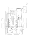
- Fig. 1 is denoted by the reference numeral 1 generally a meshed power network.
- the reference numeral 2 designates power generating devices, which are each connected via a power switch S to the power grid 1.
- the power generation devices are, for example, renewable power generation devices.
- the power switches S are part of a first safety device. Thus, for example, in the case of a short circuit, a power generating device 2 assigned to the respective power switch S can be disconnected from the power grid 1.
- a second safety device is provided.
- Each of the power switch S is for triggering a triggering device 3, z.
- a command relay power relay or a protective device assigned.
- the tripping devices 3 are connected to a control center L in Fig. 1 connected by broken lines communication links 4 connected to the data exchange.
- the reference numeral 5 denotes measuring and signal generating devices with which, for example, the current, the load flow direction and the like in the power grid 1 are detected.
- the measurement and signal generation devices 5 are connected to a controller 7 via binary signal transmission devices 6 indicated by solid lines.
- the controller 7 may be formed, for example, in the manner of an intelligent crossbar distributor.
- the controller 7 is connected to the tripping devices 3 by means of further binary signal transmission devices 8. Further is the controller 7 is connected by means of a communication link 4 with the control center L.
- the measurement and signal generation devices 5 are also connected to the control center L via communication links.
- the second safety device comprises in particular the tripping devices 3, the measuring and signal generating device 5, the controller 7 and the control center L and the communication connections provided for data exchange.
- the second safety device is a supplement to a power supply, which is protected in a conventional manner with a first safety device.
- the second safety device uses the power switches already provided by the first safety device. It also uses a network monitoring program available in the control center. However, an additional program for controlling the second safety device, in particular for activating the control 7, is provided in the control center, which extends the network monitoring program.
- the control center L has a load limit value. When the load state exceeds the load limit, the control station L sends an activation signal to the controller 7. When the controller 7 receives the activation signal, it becomes according to a selection matrix A predetermined switching paths enabled.
- the measuring and signal generating devices 5 constantly monitor the branches of the power network 1 assigned to them for faults. For this purpose, in particular, the respective current flowing through them and the respective load flow direction prevailing in them are measured, and further downshift signals occurring in them are detected. A fault is detected if further shutdown signals and / or a large change in measured values are detected.
- the measurement and signal generation device 5 is expediently set to an active operating state with a time delay. In the active operating state, upon detection of a fault by the measuring and signal generating device 5, a switch-off signal for opening at least one power switch S is generated. This switch-off signal is output without delay or delayed.
- the shutdown signal is z. B.
- the shutdown signal can also be generated only when the fault condition persists, for example, at least 5 to 7 seconds.
- the switch-off signal is forwarded according to the selection matrix A specified there on at least one predetermined switching path via at least one further binary signal transmission device 8 to at least one of the tripping devices 3.
- a trigger device 3 receives a shutdown signal, this generates a signal with the z.
- a power relay is controlled and the circuit breaker S is opened.
- a secured with the circuit breaker S is Power generating device 2 separated from the power grid 1.
- the selection matrix A can be permanently stored in the controller 7 in a so-called "offline" mode.
- a switch-off signal generated by a measuring and signal generating device 5 is forwarded on a switching path predetermined by the selection matrix A to a predetermined triggering device 3 via the corresponding further binary signal transmission device 8.
- the controller 7 it is also possible to operate the controller 7 in a so-called "online" mode.
- the selection matrix A is recalculated in the control center L on the basis of the parameters collected there by means of the program.
- the selection matrix A is then replaced recurrently by the newly computed further selection matrix A '(not shown).
- the updating of the selection matrix A on the basis of the respective load state of the power grid 1 enables an even more efficient use of the power grid 1 up to its thermal load limits.
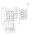
- Fig. 2 shows a block diagram of a second safety device.
- the selection matrix A stored in the controller 7 is shown by way of example on the basis of thick black lines.
- one or more transmission paths is fixed for each of a measuring and signal transmission device 5 generated shutdown signal.
- a switch-off signal is transmitted to a tripping device 3 via the binary signal transmission devices 6, 8 marked with the thick line.
- the reference numeral 9 denotes switches.
- the switches 9 are closed in the case of receiving an activation signal sent by the control station L.
- the switching paths according to the selection matrix A are switched through in the controller 7. Ie.
- a switch-off signal is generated by means of one of the measuring and signal-generating devices 5, this is rapidly and efficiently redistributed to one or more of the tripping devices 3 via the selection matrix A.
- the corresponding power switches S are opened and the thus secured power generating devices 2 separated from the power grid 1.
Priority Applications (1)
| Application Number | Priority Date | Filing Date | Title |
|---|---|---|---|
| PL13180266T PL2701257T3 (pl) | 2012-08-22 | 2013-08-13 | Sposób transportu energii elektrycznej przez rozproszoną sieć elektroenergetyczną |
Applications Claiming Priority (1)
| Application Number | Priority Date | Filing Date | Title |
|---|---|---|---|
| DE102012214927.9A DE102012214927A1 (de) | 2012-08-22 | 2012-08-22 | Verfahren zum Transport von Strom über ein vermaschtes Stromnetz |
Publications (3)
| Publication Number | Publication Date |
|---|---|
| EP2701257A2 true EP2701257A2 (fr) | 2014-02-26 |
| EP2701257A3 EP2701257A3 (fr) | 2018-01-24 |
| EP2701257B1 EP2701257B1 (fr) | 2020-07-01 |
Family
ID=48985615
Family Applications (1)
| Application Number | Title | Priority Date | Filing Date |
|---|---|---|---|
| EP13180266.2A Active EP2701257B1 (fr) | 2012-08-22 | 2013-08-13 | Procédé de transport de courant via un réseau électrique maillé |
Country Status (4)
| Country | Link |
|---|---|
| EP (1) | EP2701257B1 (fr) |
| DE (1) | DE102012214927A1 (fr) |
| ES (1) | ES2812583T3 (fr) |
| PL (1) | PL2701257T3 (fr) |
Citations (7)
| Publication number | Priority date | Publication date | Assignee | Title |
|---|---|---|---|---|
| DE4027917A1 (de) | 1990-09-03 | 1992-03-05 | Siemens Ag | Verfahren und vorrichtung zum selektiven abtrennen von leitungsabschnitten in energieversorgungsnetzen |
| DE4027918A1 (de) | 1990-09-03 | 1992-03-05 | Siemens Ag | Verfahren und vorrichtung zum selektiven abtrennen von leitungsabschnitten in energieversorgungsnetzen |
| DE4027919A1 (de) | 1990-09-03 | 1992-03-05 | Siemens Ag | Verfahren und vorrichtung zum selektiven abtrennen von leitungsabschnitten in energieversorgungsnetzen |
| DE19749698A1 (de) | 1997-10-28 | 1999-04-29 | Siemens Ag | Schutzschaltungsanordnung für ein Energieverteilungsnetz |
| DE10008185A1 (de) | 2000-02-18 | 2001-09-06 | Elbas Elek Sche Bahnsysteme In | Verfahren zum selektiven Schutz bei Kurzschlüssen in stationären Verbraucherstromkreisen |
| WO2011015587A2 (fr) | 2009-08-06 | 2011-02-10 | Sma Solar Technology Ag | Dispositif destiné à transmettre lénergie électrique dune pluralité de chaînes de modules photovoltaïques au réseau électrique |
| EP2290774A1 (fr) | 2009-08-31 | 2011-03-02 | EMforce B.V. | Dispositif et procédé pour protéger le réseau de distribution électrique contre les défauts de courant |
Family Cites Families (4)
| Publication number | Priority date | Publication date | Assignee | Title |
|---|---|---|---|---|
| US3277344A (en) * | 1963-02-06 | 1966-10-04 | Gen Electric | Static protective relays |
| US6496342B1 (en) * | 1999-02-12 | 2002-12-17 | Bitronics Inc. | Distributed monitoring and protection system for a distributed power network |
| DE10133881A1 (de) * | 2001-07-12 | 2003-01-30 | Siemens Ag | Schutzanordnung und Schutzverfahren für eine Strombahn |
| GB0813916D0 (en) * | 2008-07-31 | 2008-09-03 | Rolls Royce Plc | A Protection arrangement |
-
2012
- 2012-08-22 DE DE102012214927.9A patent/DE102012214927A1/de not_active Ceased
-
2013
- 2013-08-13 PL PL13180266T patent/PL2701257T3/pl unknown
- 2013-08-13 ES ES13180266T patent/ES2812583T3/es active Active
- 2013-08-13 EP EP13180266.2A patent/EP2701257B1/fr active Active
Patent Citations (7)
| Publication number | Priority date | Publication date | Assignee | Title |
|---|---|---|---|---|
| DE4027917A1 (de) | 1990-09-03 | 1992-03-05 | Siemens Ag | Verfahren und vorrichtung zum selektiven abtrennen von leitungsabschnitten in energieversorgungsnetzen |
| DE4027918A1 (de) | 1990-09-03 | 1992-03-05 | Siemens Ag | Verfahren und vorrichtung zum selektiven abtrennen von leitungsabschnitten in energieversorgungsnetzen |
| DE4027919A1 (de) | 1990-09-03 | 1992-03-05 | Siemens Ag | Verfahren und vorrichtung zum selektiven abtrennen von leitungsabschnitten in energieversorgungsnetzen |
| DE19749698A1 (de) | 1997-10-28 | 1999-04-29 | Siemens Ag | Schutzschaltungsanordnung für ein Energieverteilungsnetz |
| DE10008185A1 (de) | 2000-02-18 | 2001-09-06 | Elbas Elek Sche Bahnsysteme In | Verfahren zum selektiven Schutz bei Kurzschlüssen in stationären Verbraucherstromkreisen |
| WO2011015587A2 (fr) | 2009-08-06 | 2011-02-10 | Sma Solar Technology Ag | Dispositif destiné à transmettre lénergie électrique dune pluralité de chaînes de modules photovoltaïques au réseau électrique |
| EP2290774A1 (fr) | 2009-08-31 | 2011-03-02 | EMforce B.V. | Dispositif et procédé pour protéger le réseau de distribution électrique contre les défauts de courant |
Also Published As
| Publication number | Publication date |
|---|---|
| EP2701257B1 (fr) | 2020-07-01 |
| ES2812583T3 (es) | 2021-03-17 |
| DE102012214927A1 (de) | 2014-02-27 |
| EP2701257A3 (fr) | 2018-01-24 |
| PL2701257T3 (pl) | 2021-04-19 |
Similar Documents
| Publication | Publication Date | Title |
|---|---|---|
| EP2297830B1 (fr) | Disjoncteur rapide pour une batterie haute puissance dans un réseau autonome de courant continu | |
| DE102012109012B4 (de) | Schaltungsanordnung für ein Solarkraftwerk mit einer Gleichspannungsquelle für eine Offsetspannung | |
| DE102014108657A1 (de) | Schutzschaltgerät | |
| WO2011138319A1 (fr) | Procédé pour limiter la tension de générateur d'une installation photovoltaïque en cas de danger et installation photovoltaïque correspondante | |
| EP3313710A1 (fr) | Système et procédé de suppression automatique de courts-circuits dans un bus d'alimentaton | |
| DE102008010979A1 (de) | Bordnetz für ein Kraftfahrzeug | |
| DE102011089851B4 (de) | Vorrichtung zur unterbrechungsfreien Stromversorgung von elektrischen Verbrauchern und Verfahren zum Betrieb der Vorrichtung | |
| WO2010066279A1 (fr) | Procédé et appareil de protection pour surveiller une barre omnibus d'un réseau de distribution d'énergie électrique | |
| WO2010020411A1 (fr) | Dispositif de limitation des courants de fuite dans une installation à courant alternatif et basse tension | |
| EP2926455B1 (fr) | Dispositif d'interruption de courants continus dans des branches de dérivation d'un noeud de réseau de tension continue | |
| WO2012139656A1 (fr) | Réseau de distribution d'énergie et procédé d'exploitation de ce réseau | |
| WO2012139657A2 (fr) | Réseau de distribution d'énergie et son procédé de fonctionnement | |
| DE102013216939A1 (de) | Schalteranordnung in einem Stromverteilungssystem | |
| EP2701257B1 (fr) | Procédé de transport de courant via un réseau électrique maillé | |
| EP2500208B2 (fr) | Agencement de circuit de protection | |
| DE102011082342A1 (de) | Anordnung zur Stromverteilung mit zwei miteinander verbundenen Schaltern, insbesondere Leistungsschaltern für Niederspannungen | |
| DE10133881A1 (de) | Schutzanordnung und Schutzverfahren für eine Strombahn | |
| EP2880731B1 (fr) | Détection de défaillances dans un réseau d'alimentation en énergie à injection d'énergie décentralisée | |
| DE102006002245B4 (de) | Verfahren zur Überwachung eines abschaltbaren Kabels in einem elektrischen Netz, dafür geeignete Überwachungsvorrichtung sowie Überwachungssystem | |
| EP3148028A1 (fr) | Dispositif de protection pour un dispositif d'alimentation en energie et dispositif d'alimentation en energie comprenant un tel dispositif de protection | |
| DE102011078551A1 (de) | Einspeiseüberlastschutzvorrichtung und Anordnung zur Stromüberwachung | |
| DE202011109187U1 (de) | Sicherheitsvorrichtung für elektrische Anlagen | |
| DE102011082339A1 (de) | Anordnung zur Stromverteilung mit zwei miteinander verbundenen Schaltern, insbesondere Leistungsschaltern für Niederspannungen | |
| DE102022127913A1 (de) | Schutzsystem und Verfahren zum Schützen elektrischer und/oder elektronischer Einrichtungen vor einem Fehlerstrom und entsprechend eingerichtetes Kraftfahrzeug | |
| WO2014154233A1 (fr) | Boîte de jonction pour le raccordement électrique d'une pluralité de générateurs photovoltaïques et installation de production d'énergie photovoltaïque |
Legal Events
| Date | Code | Title | Description |
|---|---|---|---|
| PUAI | Public reference made under article 153(3) epc to a published international application that has entered the european phase |
Free format text: ORIGINAL CODE: 0009012 |
|
| AK | Designated contracting states |
Kind code of ref document: A2 Designated state(s): AL AT BE BG CH CY CZ DE DK EE ES FI FR GB GR HR HU IE IS IT LI LT LU LV MC MK MT NL NO PL PT RO RS SE SI SK SM TR |
|
| AX | Request for extension of the european patent |
Extension state: BA ME |
|
| RAP1 | Party data changed (applicant data changed or rights of an application transferred) |
Owner name: BAYERNWERK AG |
|
| PUAL | Search report despatched |
Free format text: ORIGINAL CODE: 0009013 |
|
| AK | Designated contracting states |
Kind code of ref document: A3 Designated state(s): AL AT BE BG CH CY CZ DE DK EE ES FI FR GB GR HR HU IE IS IT LI LT LU LV MC MK MT NL NO PL PT RO RS SE SI SK SM TR |
|
| AX | Request for extension of the european patent |
Extension state: BA ME |
|
| RIC1 | Information provided on ipc code assigned before grant |
Ipc: H02H 7/28 20060101AFI20171221BHEP Ipc: H02H 7/26 20060101ALI20171221BHEP |
|
| STAA | Information on the status of an ep patent application or granted ep patent |
Free format text: STATUS: REQUEST FOR EXAMINATION WAS MADE |
|
| 17P | Request for examination filed |
Effective date: 20180710 |
|
| RBV | Designated contracting states (corrected) |
Designated state(s): AL AT BE BG CH CY CZ DE DK EE ES FI FR GB GR HR HU IE IS IT LI LT LU LV MC MK MT NL NO PL PT RO RS SE SI SK SM TR |
|
| GRAP | Despatch of communication of intention to grant a patent |
Free format text: ORIGINAL CODE: EPIDOSNIGR1 |
|
| STAA | Information on the status of an ep patent application or granted ep patent |
Free format text: STATUS: GRANT OF PATENT IS INTENDED |
|
| INTG | Intention to grant announced |
Effective date: 20200326 |
|
| GRAS | Grant fee paid |
Free format text: ORIGINAL CODE: EPIDOSNIGR3 |
|
| GRAA | (expected) grant |
Free format text: ORIGINAL CODE: 0009210 |
|
| STAA | Information on the status of an ep patent application or granted ep patent |
Free format text: STATUS: THE PATENT HAS BEEN GRANTED |
|
| AK | Designated contracting states |
Kind code of ref document: B1 Designated state(s): AL AT BE BG CH CY CZ DE DK EE ES FI FR GB GR HR HU IE IS IT LI LT LU LV MC MK MT NL NO PL PT RO RS SE SI SK SM TR |
|
| REG | Reference to a national code |
Ref country code: AT Ref legal event code: REF Ref document number: 1287052 Country of ref document: AT Kind code of ref document: T Effective date: 20200715 Ref country code: CH Ref legal event code: EP |
|
| REG | Reference to a national code |
Ref country code: IE Ref legal event code: FG4D Free format text: LANGUAGE OF EP DOCUMENT: GERMAN |
|
| REG | Reference to a national code |
Ref country code: DE Ref legal event code: R096 Ref document number: 502013014860 Country of ref document: DE |
|
| REG | Reference to a national code |
Ref country code: DE Ref legal event code: R081 Ref document number: 502013014860 Country of ref document: DE Owner name: BAYERNWERK NETZ GMBH, DE Free format text: FORMER OWNER: BAYERNWERK AG, 93049 REGENSBURG, DE |
|
| RAP2 | Party data changed (patent owner data changed or rights of a patent transferred) |
Owner name: BAYERNWERK NETZ GMBH |
|
| REG | Reference to a national code |
Ref country code: NL Ref legal event code: FP |
|
| REG | Reference to a national code |
Ref country code: NO Ref legal event code: T2 Effective date: 20200701 |
|
| REG | Reference to a national code |
Ref country code: SE Ref legal event code: TRGR |
|
| REG | Reference to a national code |
Ref country code: GB Ref legal event code: 732E Free format text: REGISTERED BETWEEN 20200917 AND 20200923 |
|
| REG | Reference to a national code |
Ref country code: LT Ref legal event code: MG4D |
|
| PG25 | Lapsed in a contracting state [announced via postgrant information from national office to epo] |
Ref country code: BG Free format text: LAPSE BECAUSE OF FAILURE TO SUBMIT A TRANSLATION OF THE DESCRIPTION OR TO PAY THE FEE WITHIN THE PRESCRIBED TIME-LIMIT Effective date: 20201001 |
|
| REG | Reference to a national code |
Ref country code: SK Ref legal event code: T3 Ref document number: E 35414 Country of ref document: SK |
|
| PG25 | Lapsed in a contracting state [announced via postgrant information from national office to epo] |
Ref country code: FI Free format text: LAPSE BECAUSE OF FAILURE TO SUBMIT A TRANSLATION OF THE DESCRIPTION OR TO PAY THE FEE WITHIN THE PRESCRIBED TIME-LIMIT Effective date: 20200701 Ref country code: GR Free format text: LAPSE BECAUSE OF FAILURE TO SUBMIT A TRANSLATION OF THE DESCRIPTION OR TO PAY THE FEE WITHIN THE PRESCRIBED TIME-LIMIT Effective date: 20201002 Ref country code: HR Free format text: LAPSE BECAUSE OF FAILURE TO SUBMIT A TRANSLATION OF THE DESCRIPTION OR TO PAY THE FEE WITHIN THE PRESCRIBED TIME-LIMIT Effective date: 20200701 Ref country code: PT Free format text: LAPSE BECAUSE OF FAILURE TO SUBMIT A TRANSLATION OF THE DESCRIPTION OR TO PAY THE FEE WITHIN THE PRESCRIBED TIME-LIMIT Effective date: 20201102 Ref country code: LT Free format text: LAPSE BECAUSE OF FAILURE TO SUBMIT A TRANSLATION OF THE DESCRIPTION OR TO PAY THE FEE WITHIN THE PRESCRIBED TIME-LIMIT Effective date: 20200701 |
|
| REG | Reference to a national code |
Ref country code: NL Ref legal event code: PD Owner name: BAYERNWERK NETZ GMBH; DE Free format text: DETAILS ASSIGNMENT: CHANGE OF OWNER(S), ASSIGNMENT; FORMER OWNER NAME: BAYERNWERK AG Effective date: 20210125 |
|
| PG25 | Lapsed in a contracting state [announced via postgrant information from national office to epo] |
Ref country code: IS Free format text: LAPSE BECAUSE OF FAILURE TO SUBMIT A TRANSLATION OF THE DESCRIPTION OR TO PAY THE FEE WITHIN THE PRESCRIBED TIME-LIMIT Effective date: 20201101 Ref country code: LV Free format text: LAPSE BECAUSE OF FAILURE TO SUBMIT A TRANSLATION OF THE DESCRIPTION OR TO PAY THE FEE WITHIN THE PRESCRIBED TIME-LIMIT Effective date: 20200701 Ref country code: RS Free format text: LAPSE BECAUSE OF FAILURE TO SUBMIT A TRANSLATION OF THE DESCRIPTION OR TO PAY THE FEE WITHIN THE PRESCRIBED TIME-LIMIT Effective date: 20200701 |
|
| REG | Reference to a national code |
Ref country code: AT Ref legal event code: PC Ref document number: 1287052 Country of ref document: AT Kind code of ref document: T Owner name: BAYERNWERK NETZ GMBH, DE Effective date: 20210118 |
|
| REG | Reference to a national code |
Ref country code: ES Ref legal event code: FG2A Ref document number: 2812583 Country of ref document: ES Kind code of ref document: T3 Effective date: 20210317 |
|
| PG25 | Lapsed in a contracting state [announced via postgrant information from national office to epo] |
Ref country code: MC Free format text: LAPSE BECAUSE OF FAILURE TO SUBMIT A TRANSLATION OF THE DESCRIPTION OR TO PAY THE FEE WITHIN THE PRESCRIBED TIME-LIMIT Effective date: 20200701 |
|
| REG | Reference to a national code |
Ref country code: DE Ref legal event code: R097 Ref document number: 502013014860 Country of ref document: DE |
|
| PG25 | Lapsed in a contracting state [announced via postgrant information from national office to epo] |
Ref country code: DK Free format text: LAPSE BECAUSE OF FAILURE TO SUBMIT A TRANSLATION OF THE DESCRIPTION OR TO PAY THE FEE WITHIN THE PRESCRIBED TIME-LIMIT Effective date: 20200701 Ref country code: EE Free format text: LAPSE BECAUSE OF FAILURE TO SUBMIT A TRANSLATION OF THE DESCRIPTION OR TO PAY THE FEE WITHIN THE PRESCRIBED TIME-LIMIT Effective date: 20200701 Ref country code: LU Free format text: LAPSE BECAUSE OF NON-PAYMENT OF DUE FEES Effective date: 20200813 Ref country code: SM Free format text: LAPSE BECAUSE OF FAILURE TO SUBMIT A TRANSLATION OF THE DESCRIPTION OR TO PAY THE FEE WITHIN THE PRESCRIBED TIME-LIMIT Effective date: 20200701 Ref country code: RO Free format text: LAPSE BECAUSE OF FAILURE TO SUBMIT A TRANSLATION OF THE DESCRIPTION OR TO PAY THE FEE WITHIN THE PRESCRIBED TIME-LIMIT Effective date: 20200701 |
|
| PLBE | No opposition filed within time limit |
Free format text: ORIGINAL CODE: 0009261 |
|
| STAA | Information on the status of an ep patent application or granted ep patent |
Free format text: STATUS: NO OPPOSITION FILED WITHIN TIME LIMIT |
|
| REG | Reference to a national code |
Ref country code: BE Ref legal event code: MM Effective date: 20200831 |
|
| PG25 | Lapsed in a contracting state [announced via postgrant information from national office to epo] |
Ref country code: AL Free format text: LAPSE BECAUSE OF FAILURE TO SUBMIT A TRANSLATION OF THE DESCRIPTION OR TO PAY THE FEE WITHIN THE PRESCRIBED TIME-LIMIT Effective date: 20200701 |
|
| 26N | No opposition filed |
Effective date: 20210406 |
|
| PG25 | Lapsed in a contracting state [announced via postgrant information from national office to epo] |
Ref country code: BE Free format text: LAPSE BECAUSE OF NON-PAYMENT OF DUE FEES Effective date: 20200831 Ref country code: SI Free format text: LAPSE BECAUSE OF FAILURE TO SUBMIT A TRANSLATION OF THE DESCRIPTION OR TO PAY THE FEE WITHIN THE PRESCRIBED TIME-LIMIT Effective date: 20200701 Ref country code: IE Free format text: LAPSE BECAUSE OF NON-PAYMENT OF DUE FEES Effective date: 20200813 |
|
| PG25 | Lapsed in a contracting state [announced via postgrant information from national office to epo] |
Ref country code: TR Free format text: LAPSE BECAUSE OF FAILURE TO SUBMIT A TRANSLATION OF THE DESCRIPTION OR TO PAY THE FEE WITHIN THE PRESCRIBED TIME-LIMIT Effective date: 20200701 Ref country code: MT Free format text: LAPSE BECAUSE OF FAILURE TO SUBMIT A TRANSLATION OF THE DESCRIPTION OR TO PAY THE FEE WITHIN THE PRESCRIBED TIME-LIMIT Effective date: 20200701 Ref country code: CY Free format text: LAPSE BECAUSE OF FAILURE TO SUBMIT A TRANSLATION OF THE DESCRIPTION OR TO PAY THE FEE WITHIN THE PRESCRIBED TIME-LIMIT Effective date: 20200701 |
|
| PG25 | Lapsed in a contracting state [announced via postgrant information from national office to epo] |
Ref country code: MK Free format text: LAPSE BECAUSE OF FAILURE TO SUBMIT A TRANSLATION OF THE DESCRIPTION OR TO PAY THE FEE WITHIN THE PRESCRIBED TIME-LIMIT Effective date: 20200701 |
|
| PGFP | Annual fee paid to national office [announced via postgrant information from national office to epo] |
Ref country code: NL Payment date: 20230823 Year of fee payment: 11 |
|
| PGFP | Annual fee paid to national office [announced via postgrant information from national office to epo] |
Ref country code: NO Payment date: 20230822 Year of fee payment: 11 Ref country code: IT Payment date: 20230831 Year of fee payment: 11 Ref country code: GB Payment date: 20230824 Year of fee payment: 11 Ref country code: ES Payment date: 20230918 Year of fee payment: 11 Ref country code: CZ Payment date: 20230728 Year of fee payment: 11 Ref country code: CH Payment date: 20230902 Year of fee payment: 11 Ref country code: AT Payment date: 20230818 Year of fee payment: 11 |
|
| PGFP | Annual fee paid to national office [announced via postgrant information from national office to epo] |
Ref country code: SK Payment date: 20230803 Year of fee payment: 11 Ref country code: SE Payment date: 20230823 Year of fee payment: 11 Ref country code: PL Payment date: 20230731 Year of fee payment: 11 Ref country code: FR Payment date: 20230821 Year of fee payment: 11 Ref country code: DE Payment date: 20230822 Year of fee payment: 11 |