EP2700966A1 - Battery state estimation device and method - Google Patents
Battery state estimation device and method Download PDFInfo
- Publication number
- EP2700966A1 EP2700966A1 EP13761507.6A EP13761507A EP2700966A1 EP 2700966 A1 EP2700966 A1 EP 2700966A1 EP 13761507 A EP13761507 A EP 13761507A EP 2700966 A1 EP2700966 A1 EP 2700966A1
- Authority
- EP
- European Patent Office
- Prior art keywords
- battery
- soc
- state
- estimating
- variable
- Prior art date
- Legal status (The legal status is an assumption and is not a legal conclusion. Google has not performed a legal analysis and makes no representation as to the accuracy of the status listed.)
- Granted
Links
Images

Classifications
-
- G—PHYSICS
- G01—MEASURING; TESTING
- G01R—MEASURING ELECTRIC VARIABLES; MEASURING MAGNETIC VARIABLES
- G01R31/00—Arrangements for testing electric properties; Arrangements for locating electric faults; Arrangements for electrical testing characterised by what is being tested not provided for elsewhere
- G01R31/36—Arrangements for testing, measuring or monitoring the electrical condition of accumulators or electric batteries, e.g. capacity or state of charge [SoC]
- G01R31/382—Arrangements for monitoring battery or accumulator variables, e.g. SoC
- G01R31/3842—Arrangements for monitoring battery or accumulator variables, e.g. SoC combining voltage and current measurements
-
- G—PHYSICS
- G01—MEASURING; TESTING
- G01R—MEASURING ELECTRIC VARIABLES; MEASURING MAGNETIC VARIABLES
- G01R19/00—Arrangements for measuring currents or voltages or for indicating presence or sign thereof
- G01R19/165—Indicating that current or voltage is either above or below a predetermined value or within or outside a predetermined range of values
-
- G—PHYSICS
- G01—MEASURING; TESTING
- G01R—MEASURING ELECTRIC VARIABLES; MEASURING MAGNETIC VARIABLES
- G01R31/00—Arrangements for testing electric properties; Arrangements for locating electric faults; Arrangements for electrical testing characterised by what is being tested not provided for elsewhere
- G01R31/36—Arrangements for testing, measuring or monitoring the electrical condition of accumulators or electric batteries, e.g. capacity or state of charge [SoC]
-
- G—PHYSICS
- G01—MEASURING; TESTING
- G01R—MEASURING ELECTRIC VARIABLES; MEASURING MAGNETIC VARIABLES
- G01R31/00—Arrangements for testing electric properties; Arrangements for locating electric faults; Arrangements for electrical testing characterised by what is being tested not provided for elsewhere
- G01R31/36—Arrangements for testing, measuring or monitoring the electrical condition of accumulators or electric batteries, e.g. capacity or state of charge [SoC]
- G01R31/367—Software therefor, e.g. for battery testing using modelling or look-up tables
-
- G—PHYSICS
- G01—MEASURING; TESTING
- G01R—MEASURING ELECTRIC VARIABLES; MEASURING MAGNETIC VARIABLES
- G01R31/00—Arrangements for testing electric properties; Arrangements for locating electric faults; Arrangements for electrical testing characterised by what is being tested not provided for elsewhere
- G01R31/36—Arrangements for testing, measuring or monitoring the electrical condition of accumulators or electric batteries, e.g. capacity or state of charge [SoC]
- G01R31/392—Determining battery ageing or deterioration, e.g. state of health
Definitions
- the present disclosure relates to an apparatus and method for estimating a battery state, and more particularly, to an apparatus and method for estimating a more accurate battery state such as a state of charge (SOC) of a battery by using an extended Kalman filter in consideration of a current offset of a current sensor included in the battery.
- SOC state of charge
- lithium secondary batteries have little to no memory effect in comparison with nickel-based secondary batteries, and thus lithium secondary batteries are gaining a lot of attention for their advantages of free charging/discharging, low self-discharging, and high energy density.
- Hybrid vehicles and electric vehicles are supplied with power for driving the vehicles from the charging/discharging energy of battery packs. Therefore, in comparison with vehicles powered by an engine alone, they have higher fuel efficiency and can eliminate or lessen the emission of pollutants, which adds to the appeal of hybrid vehicles and electric vehicles. Accordingly, research and development for vehicle batteries essential to hybrid vehicles and electric vehicles have intensified with gaining interest.
- a battery is used for various kinds of mobile devices such as a notebook or a vehicle and has a limit in service time. Therefore, it is important to check accurate information of the SOC of the battery.
- the SOC is useful in weighing up an available service time of the battery and therefore is considered to be very important information to a user of the corresponding device.
- a general device using a battery such as a notebook, a cellular phone or a vehicle estimates SOC of the battery, checks an available service time or capacity of the battery from the estimated SOC, and provides the information to the user.
- the SOC of a battery generally represents a residual capacity as a percentage of Full Charge Capacity (FCC) of the battery.
- FCC Full Charge Capacity
- various methods may be used; however, the most representative method is estimating the SOC by means of current integration.
- current integration input/output currents of the battery are accumulated and added or subtracted to/from an initial capacity to obtain the SOC.
- a battery state such as SOC is not accurately estimated due to a current offset as described above, serious inconvenience or damage may be caused to a user.
- SOC of the battery is estimated excessively higher than its actual value, the user may not charge the battery as the user may not be able to predict exhaustion of SOC of the battery, which may cause the battery to fully discharge while the vehicle is running.
- a battery fully discharges while a vehicle is running can lead to many inconveniences such as vehicles being towed or even traffic accidents.
- the present disclosure is designed to solve the problems of the related art, and therefore the present disclosure is directed to providing an apparatus and method which may more accurately estimate a battery state such as a state of charge (SOC) of a battery by using an extended Kalman filter by determining whether to trust a current sensor or a battery model according to a current offset of the current sensor.
- SOC state of charge
- an apparatus for estimating a battery state which includes a measurement unit for measuring a terminal voltage, a charging/discharging current and a current offset value of a battery; a prediction unit for predicting a state variable and an output variable by using a state equation which includes a state of charge (SOC) and an overpotential of the battery as state variables and includes a terminal voltage of the battery as an output variable; a correction unit for correcting the predicted state variable by comparing the predicted output variable with an output variable measured by the measurement unit; a SOC estimation unit for estimating SOC of the battery by means of the corrected state variable; and a control unit for selecting a single state variable to estimate SOC of the battery according to the measured current offset value, so that the SOC estimation unit estimates SOC of the battery by means of the selected state variable.
- SOC state of charge
- control unit may select the overpotential as a state variable for estimating the SOC, so that the SOC estimation unit estimates SOC of the battery by means of the corrected overpotential.
- the SOC estimation unit may calculate an open circuit voltage (OCV) of the battery by means of the corrected overpotential and estimate SOC of the battery by means of the calculated OCV.
- OCV open circuit voltage
- control unit may select SOC as a state variable for estimating the SOC, so that the SOC estimation unit estimates the corrected SOC as SOC of the battery.
- the apparatus for estimating a battery state may further include a SOH estimation unit for estimating SOH of the battery according to the SOC estimated by the SOC estimation unit.
- a battery management system which includes the apparatus for estimating a battery state as described above.
- a vehicle which includes the apparatus for estimating a battery state as described above.
- a method for estimating a battery state which includes measuring a terminal voltage, a charging/discharging current and a current offset value of a battery; predicting a state variable and an output variable by using a state equation which includes SOC and an overpotential of the battery as state variables and includes a terminal voltage of the battery as an output variable; correcting the predicted state variable by comparing the predicted output variable with a measured output variable; and selecting a single state variable to estimate SOC of the battery according to the measured current offset value and estimating SOC of the battery by means of the selected state variable.
- the battery state since a battery state such as SOC is estimated using an extended Kalman filter, the battery state may be estimated more accurately.
- the SOC of the battery may be accurately estimated.
- a battery state since whether to estimate an SOC according to a measured current value or an overpotential value is determined based on a current offset value, a battery state may be more accurately estimated in consideration of a current offset.
- SOC is determined by means of the overpotential value included in a state variable, while if the current offset value is not greater than the reference value, the estimated SOC value is determined according to SOC included in the state variable. Therefore, if the current offset value exceeds a certain level, SOC of the battery is estimated depending on the battery model, while if the current offset value is not greater than a certain level, SOC of the battery is estimated depending on the current sensor. Therefore, SOC may be suitably estimated according to the current offset.
- a user since a user may be provided with a full-discharge point of a battery despite an offset of a current sensor, a user may better cope with a full-discharge state by charging the battery or the like, thereby preventing any unexpected accidents, damages or similar inconveniences.
- Fig. 1 is a block diagram schematically showing a function configuration of an apparatus for estimating a battery state (hereinafter, also referred to as a "battery state estimating apparatus") according to an embodiment of the present disclosure.
- the battery state estimating apparatus may include a measurement unit 110, a prediction unit 120, a correction unit 130, a control unit 160 and a SOC estimation unit 140.
- the measurement unit 110 measures a terminal voltage and a charging/discharging current of a battery.
- the charging/discharging current of a battery may be measured by a current measurement unit provided at a conventional battery pack, such as a current sensor.
- the measurement unit 110 measures a current offset value of a battery.
- the current offset value of a battery means a difference between a measured current value and an actual current value flowing along a charge/discharge path of the battery, which is caused by an offset of the current sensor (the current measurement unit).
- the current offset value may be regarded as 2A. This current offset phenomenon may occur due to degradation of the current sensor or the like.
- the measurement unit 110 may measure the current offset value in various ways, for example by measuring a voltage of the battery. For example, when a current does not flow through a battery, the measurement unit 110 may determine the current offset value by measuring a value sensed by the current sensor.
- the prediction unit 120 and the correction unit 130 predict and correct a state variable and an output variable by using an algorithm.
- the prediction unit 120 and the correction unit 130 according to the present disclosure may use an extended Kalman filter as an algorithm for predicting and correcting the state variable and the output variable.
- the Kalman filter is one of the techniques for modeling operations of a battery and predicting SOC based on the model and circularly predicts an internal state of a dynamic system by using output values of a system.
- the extended Kalman filter uses the basic principle of the Kalman filter and is applied to a non-linear function, instead of a linear function.
- SOC of a battery is estimated by using the extended Kalman filter.
- the principle of the extended Kalman filter is well known in the art, and this specification will focus on the distinctive features of the present disclosure.
- the prediction unit 120 predicts a state variable and an output variable by using a state equation.
- the state equation may include a system equation in relation with the state variable and a measurement equation in relation with the output variable.
- the state variable of the state equation may include SOC and overpotential of a battery
- the output variable of the state equation may include a terminal voltage of the battery.
- Equation 1 is a general system equation of the extended Kalman filter
- Equation 2 is a general measurement equation
- k represents a time step.
- x k represents a state variable which is to be estimated
- u k is a current of the battery
- w k is a system noise component.
- y k is an output variable which may be measured
- z k is a measurement noise component.
- the prediction unit 120 may include SOC and overpotential of the battery as a state variable and include a terminal voltage of the battery as an output variable.
- SOC of the battery represents a state of charge of the battery
- the overpotential of the battery means a value obtained by subtracting an open circuit voltage (OCV) from the terminal voltage of the battery.
- Equations 3 and 4 k represents a time step, x 1(k+1) and x 2(k+1) respectively represents SOC and overpotential of a present stage, namely predicted values of SOC and overpotential, and x 1(k) and x 2(k) respectively represent SOC and overpotential of a previous stage.
- u 1(k) and u 2(k) respectively represent a present battery current and a previous battery current, and w 1(k) and w 2(k) represent system noise components.
- A, B and C are variables representing characteristics of a battery, such as battery resistance and capacitance, which may be determined through experiments.
- ⁇ ekf is a variable in relation with capacity of the battery, which may be determined through experiments.
- y k represents a terminal voltage of the battery
- H 1 is a variable representing a correlation between SOC and OCV, which may be determined through experiments.
- the prediction unit 120 may predict a state variable by using a system equation like Equation 3 and predict an output variable by using an output equation like Equation 4.
- the prediction unit 120 may predict a state variable in relation with SOC and overpotential by using the input of an initial parameter. However, in the following stages, the prediction unit 120 may predict a state variable by means of the state variable corrected by the correction unit 130.
- the prediction unit 120 may predict a dispersion of errors caused by state variable estimation, namely estimated error dispersion.
- the estimated error dispersion (P k ) may be calculated according to Equation 5 below.
- P k A k - 1 ⁇ P k - 1 ⁇ A k - 1 T + WQW T
- a k-1 represents 1 0 0 C
- a k-1 T represents a transposed matrix of A k-1
- W represents W 1 W 2
- Q represents a process noise parameter
- WQW T represents a dispersion value of system noise.
- the correction unit 130 compares the output variable predicted by the prediction unit 120 with the output variable measured by the measurement unit 110. In addition, the correction unit 130 corrects the predicted state variable by means of the comparison result.
- the correction unit 130 may generate a Kalman gain (K k ), namely a gain factor, by using Equation 6 below.
- K k P k ⁇ C k T P k ⁇ C k T + VRV T
- V and R represent measurement noise parameters
- VRV T a dispersion value of measurement noise
- the correction unit 130 may correct the predicted state variable by means of the predicted output variable and the measured output variable together with the gain factor as in Equation 7 below.
- x k ' represents a predicted state variable
- x k represents a corrected value
- K k represents a gain factor, namely a Kalman gain
- y k represents a measured output variable, namely a measured battery terminal voltage
- g (x k , u k ) represents an output variable predicted by the prediction unit 120, namely a predicted battery terminal voltage.
- the corrected state variable may be input as a previous value for predicting a state variable of a next stage.
- x k ' of Equation 7 may be input as x k of Equation 1 and used to predict a state variable x (k+1) of a next stage.
- correction unit 130 may correct the estimated error dispersion predicted by the prediction unit 120 by using the Kalman gain, as expressed in Equation 8 below.
- P k ⁇ 1 - K k ⁇ C k ⁇ P k
- P k ' represents a corrected value of the predicted estimated error dispersion
- P k represents a Kalman gain
- C k represents [ H 1 1].
- the corrected estimated error dispersion may be input as a previous value for predicting an estimated error dispersion of a next stage.
- P k ' of Equation 8 may be input as P k-1 of Equation 5 and used to predict an estimated error dispersion P k of a next stage.
- the SOC estimation unit 140 estimates SOC of the battery by means of the state variable corrected by the correction unit 130.
- the state variable corrected by the correction unit 130 may include SOC and overpotential. Therefore, the SOC estimation unit 140 may estimate SOC by means of the SOC corrected by the correction unit 130 or the overpotential corrected by the correction unit 130.
- the control unit 160 selects a single state variable for estimating SOC of the battery according to the current offset value measured by the measurement unit 110.
- the SOC estimation unit 140 uses the corrected SOC or the corrected overpotential as a state variable in order to estimate SOC, and the control unit 160 may select which state variable is used between them.
- control unit 160 may select one of the corrected SOC and the corrected overpotential and allow the SOC estimation unit 140 to estimate SOC of the battery by means of the selected state variable.
- control unit 160 may determine which state variable is used to estimate SOC of the battery according to the current offset value measured by the measurement unit 110.
- control unit 160 may compare the measured current offset value with a reference value.
- the reference value is a current value to be compared with the measured value having a current offset and may be a predetermined value.
- the reference value may be a maximum value of current errors with which the current value measured by the current sensor may be regarded reliable when estimating SOC of the battery.
- the reference value may be 0A.
- the state variable for estimating SOC may be different depending on the presence of the current offset value.
- the reference value having a current offset may be stored in advance in a memory provided at the inside or outside of the control unit 160.
- the control unit 160 selects the overpotential as a state variable for estimating SOC. Therefore, in this case, the SOC estimation unit 140 may estimate SOC of the battery by means of the overpotential corrected by the correction unit 130.
- Equation 7 x 2(k+1) which is a state variable in relation with the overpotential in Equation 3 may be corrected by Equation 7 and used to estimate SOC of the battery.
- the SOC estimation unit 140 may calculate an open circuit voltage (OCV) of the battery by means of the corrected overpotential and estimate SOC of the battery by means of the calculated OCV.
- OCV open circuit voltage
- the relation between OCV and SOC of the battery may be stored in a storage device such as a memory provided at the inside or outside of the control unit 160 in a form of a mathematical formula or table, by means of experimental measurement or the like.
- the predicted and corrected SOC (x 1(k) ) included as a state variable is determined by means of the measured current value.
- the current offset value is greater than the reference value, the current sensor is not reliable and thus it is inevitable that the SOC determined by means of the measured current value has many errors from the actual SOC. Therefore, according to the embodiment of the present disclosure, when the current offset value is greater than the reference value, the corrected overpotential is used as a state variable instead of the corrected SOC to estimate SOC, thereby allowing more accurate estimation of SOC.
- the current offset value is greater than the reference value, SOC of the battery is estimated depending on the battery model, while the current sensor is not trusted.
- the control unit 160 may select SOC as a state variable for estimating SOC. Therefore, in this case, the SOC estimation unit 140 may estimate the SOC corrected by the correction unit 130 as SOC of the battery.
- a value obtained by correcting x 1(k+1) , predicted in Equation 3 for SOC, according to Equation 7 may be calculated as an estimated SOC value of the battery.
- the current offset value is not greater than the reference value, the current offset is regarded negligible. Therefore, in this case, the predicted and corrected SOC included as a state variable may be intactly regarded as an estimated SOC value of the battery. In other words, if the current offset value is not greater than the reference value, the current sensor may be trusted and the SOC determined by means of the measured current value may be used as an estimated SOC value of the battery.
- control unit 160 may determine which state variable is used to estimate SOC.
- control unit 160 may determine which state variable is used, by changing a system noise component of the state equation.
- Equation 3 w 1(k) and w 2(k) represent system noise components, and the control unit 160 may determine which state variable is used to estimate SOC by changing w 1(k) and w 2(k) .
- control unit 160 may determine which state variable is used to estimate SOC, by changing a ratio of the system noise component with respect to state variables in the state equation according to the measured current offset value.
- the control unit 160 may select overpotential as a state variable for estimating SOC. For this, the control unit 160 may change a ratio of w 1(k) which is a system noise component with respect to the state variable x 1(k) to w 2(k) which is a system noise component with respect to the state variable x 2(k) , for SOC, namely w 1(k) :w 2(k) .
- the control unit 160 sets w 1(k) :w 2(k) as 1:0.1, and then if the current offset value is 2A greater than the reference value, the control unit 160 may change w 1(k) :w 2(k) into 1:0.01. In other words, if the current offset value is greater than the reference value, the control unit may change a parameter w 2 from 0.1 to 0.01 in the meaning that the current sensor is not trusted but the battery model is trusted. In addition, in this case, if the current offset value becomes smaller than the reference value later, the control unit may change the parameter w 2 from 0.01 to 0.1 again so that the current sensor is trusted and a sensed current value may give an influence on the algorithm.
- control unit 160 increases the size of w 1(k) with respect to w 2(k) , thereby allowing SOC to be estimated according to x 1(k) .
- the measurement unit 110 may measure a temperature of the battery.
- the control unit 160 may change a ratio of the system noise component with respect to state variables according to the battery temperature measured by the measurement unit 110.
- the control unit 160 may select SOC as a state variable for estimating SOC of the battery. In this case, the control unit 160 may allow the SOC estimation unit 140 to estimate the corrected SOC according to Equation 7 to be estimated as SOC of the battery.
- the battery temperature is low, the reliability of battery SOC estimation using OCV or the like may deteriorate. Therefore, in this embodiment, if the battery temperature is lower than a predetermined level, the SOC predicted and corrected as a state variable may be intactly used as the estimated SOC value of the battery. In other words, if the battery temperature is not higher than a predetermined temperature, the battery model according to OCV of the battery is not trusted, but the current sensor is trusted.
- the predetermined temperature may be experimentally determined in advance as a lowest temperature which represents a maximum error allowable when estimating SOC of the battery according to OCV.
- the predetermined temperature may be stored in advance in a memory provided at the inside or outside of the control unit 160.
- the control unit 160 may calculate a value obtained by correcting the state variable x 1(k+1) for SOC of Equation 3 according to Equation 7 as the estimated SOC value.
- the battery state estimating apparatus may further include a SOH estimation unit 150.
- the SOH estimation unit 150 may estimate a state of health (SOH) of the battery by means of the SOC estimated by the SOC estimation unit 140.
- the performance of the battery such as power and capacity may degrade due to continuous use, and therefore SOH of the battery may continuously decrease.
- the SOH of the battery may be estimated according to the SOC of the battery, which is obvious to those skilled in the art and not described in detail here.
- the current offset may also be considered when estimating the SOH. Therefore, according to the embodiment of the present disclosure, SOH of the battery may be predicted more accurately in consideration of the current offset.
- the battery state estimating apparatus may be implemented as being included in a battery management system (BMS) of a battery pack.
- BMS battery management system
- the battery management system according to the present disclosure may include the battery state estimating apparatus described above.
- the battery management system is a management device for controlling charging/discharging operations of a battery pack as a whole, and such a BMS is generally included in a battery pack protection device.
- the BMS may include a micro controller unit (MCU), and the control unit 160 of the battery state estimating apparatus may be implemented using such a MCU.
- MCU micro controller unit
- the battery state estimating apparatus may be included in a vehicle.
- an electric vehicle including a hybrid vehicle, supplies a driving power of a motor by using a battery, and thus it is very important to estimate a battery state such as SOC when operating the battery. Since the vehicle according to the present disclosure includes the battery state estimating apparatus described above, even though an offset of a current sensor occurs, SOC and SOH of the battery may be estimated more accurately.
- Fig. 2 is a schematic flowchart for illustrating a method for estimating a battery state according to an embodiment of the present disclosure.
- a subject of each operation may be a component of the battery state estimating apparatus described above.
- the method for estimating a battery state measures a terminal voltage, a charging/discharging current and a current offset value of a battery (S110).
- the terminal voltage, the charging/discharging current and the current offset value of a battery does not have to be measured at the same time. In particular, it is not mandatory to measure the terminal voltage or the current offset value of the battery before Step S 120.
- a state equation including SOC and overpotential of the battery as a state variable namely a system equation
- a measured current value is input thereto to predict a state variable (S120).
- an initial parameter of the battery may be input as the state variable.
- a predicted state variable is input to a state equation including a terminal voltage of the battery as an output variable, namely an output equation, to predict an output variable (S130).
- the output variable predicted as above is compared with the measured output variable to correct the predicted state variable (S160).
- the terminal voltage of the battery predicted in Step S130 is compared with the terminal voltage of the battery measured in Step S110, and the predicted state variable may be corrected according to the comparison result in Step S120.
- an estimated error dispersion P k may be predicted (S 140), and a Kalman gain K k may be calculated as a gain factor by means of the estimated error dispersion result (S150).
- the Kalman gain calculated in Step S150 may be used to correct the state variable in Step S160 together with the terminal voltage predicted in Step S130 and the terminal voltage measured in Step S110.
- the corrected state variable may include a state variable in relation with SOC of the battery and a state variable in relation with overpotential of the battery, and one of these state variables may be selected to estimate SOC of the battery in Step S170.
- the state variable may be selected according to the current offset value measured in Step S110.
- Step S170 a single state variable is selected to estimate SOC of the battery according to the current offset value of the battery, and SOC of the battery is estimated by means of the selected state variable. For example, if the current offset value measured in Step S110 is greater than the reference value, in Step S170, SOC may be estimated by means of the corrected overpotential.
- the state variable corrected in Step S160 may be input as a previous value in Step S 120 and used to predict a state variable of a next stage.
- the estimated error dispersion may be further corrected (S180).
- the estimated error dispersion value predicted in Step S140 may be corrected according to the Kalman gain calculated in Step S150, and the estimated error dispersion value corrected as described above may be input as a previous value in Step S 140 and used to predict an estimated error dispersion of a next stage.
- unit just represents a logic component and is not limited to a physically distinguishable component, as apparent to those skilled in the art.
Landscapes
- Physics & Mathematics (AREA)
- General Physics & Mathematics (AREA)
- Secondary Cells (AREA)
Abstract
Description
- The present disclosure relates to an apparatus and method for estimating a battery state, and more particularly, to an apparatus and method for estimating a more accurate battery state such as a state of charge (SOC) of a battery by using an extended Kalman filter in consideration of a current offset of a current sensor included in the battery.
- The present application claims priority to Korean Patent Application No.
10-2012-0027284 - Recently, with the active development of storage batteries, robots, satellites, and the like, along with the dramatically increasing demand for portable electronic products such as laptop computers, video cameras, mobile phones, and the like, research and development for high-performance secondary batteries capable of repeatedly charging and discharging has been actively made.
- Currently, nickel-cadmium batteries, nickel-metal hydride batteries, nickel-zinc batteries, lithium secondary batteries, and the like are used as commercial secondary batteries. Among them, lithium secondary batteries have little to no memory effect in comparison with nickel-based secondary batteries, and thus lithium secondary batteries are gaining a lot of attention for their advantages of free charging/discharging, low self-discharging, and high energy density.
- Particularly, with the steady exhaustion of carbon energy and increasing interest in the environment, the demand for hybrid vehicles and electric vehicles is recently gradually increasing all over the world including United States, Europe, Japan, and the Republic of Korea. Hybrid vehicles and electric vehicles are supplied with power for driving the vehicles from the charging/discharging energy of battery packs. Therefore, in comparison with vehicles powered by an engine alone, they have higher fuel efficiency and can eliminate or lessen the emission of pollutants, which adds to the appeal of hybrid vehicles and electric vehicles. Accordingly, research and development for vehicle batteries essential to hybrid vehicles and electric vehicles have intensified with gaining interest.
- As described above, a battery is used for various kinds of mobile devices such as a notebook or a vehicle and has a limit in service time. Therefore, it is important to check accurate information of the SOC of the battery. The SOC is useful in weighing up an available service time of the battery and therefore is considered to be very important information to a user of the corresponding device. For this reason, a general device using a battery such as a notebook, a cellular phone or a vehicle estimates SOC of the battery, checks an available service time or capacity of the battery from the estimated SOC, and provides the information to the user.
- The SOC of a battery generally represents a residual capacity as a percentage of Full Charge Capacity (FCC) of the battery. In order to estimate the SOC of a battery, various methods may be used; however, the most representative method is estimating the SOC by means of current integration. In the current integration, input/output currents of the battery are accumulated and added or subtracted to/from an initial capacity to obtain the SOC.
- In this current integration method, since SOC is estimated from a current measured by a current sensor installed on a charge/discharge path of the battery, accurate sensing of the current sensor is very important. However, the current sensor may cause a current offset between an actual current and a measured current value due to degradation. If such a current offset occurs, an actual SOC may be different from the estimated SOC due to a current offset value which is a difference between the measured current value and the actual current value. In particular, when SOC of a battery is estimated using an algorithm such as a Kalman filter, the difference in SOC caused by such a current offset value is continually accumulated, which gradually increases an error of the estimated SOC value. However, a conventional SOC estimation technique does not consider such a current offset when estimating SOC, which results in inaccurate estimation of SOC.
- If a battery state such as SOC is not accurately estimated due to a current offset as described above, serious inconvenience or damage may be caused to a user. In particular, in case of a battery used for an electric vehicle, if SOC of the battery is estimated excessively higher than its actual value, the user may not charge the battery as the user may not be able to predict exhaustion of SOC of the battery, which may cause the battery to fully discharge while the vehicle is running. In addition, if a battery fully discharges while a vehicle is running can lead to many inconveniences such as vehicles being towed or even traffic accidents.
- The present disclosure is designed to solve the problems of the related art, and therefore the present disclosure is directed to providing an apparatus and method which may more accurately estimate a battery state such as a state of charge (SOC) of a battery by using an extended Kalman filter by determining whether to trust a current sensor or a battery model according to a current offset of the current sensor.
- Other objects and advantages of the present disclosure will be understood from the following descriptions and become apparent by the embodiments of the present disclosure. In addition, it is understood that the objects and advantages of the present disclosure may be implemented by components defined in the appended claims or their combinations.
- In one aspect of the present disclosure, there is provided an apparatus for estimating a battery state, which includes a measurement unit for measuring a terminal voltage, a charging/discharging current and a current offset value of a battery; a prediction unit for predicting a state variable and an output variable by using a state equation which includes a state of charge (SOC) and an overpotential of the battery as state variables and includes a terminal voltage of the battery as an output variable; a correction unit for correcting the predicted state variable by comparing the predicted output variable with an output variable measured by the measurement unit; a SOC estimation unit for estimating SOC of the battery by means of the corrected state variable; and a control unit for selecting a single state variable to estimate SOC of the battery according to the measured current offset value, so that the SOC estimation unit estimates SOC of the battery by means of the selected state variable.
- Preferably, when the measured current offset value is greater than a reference value, the control unit may select the overpotential as a state variable for estimating the SOC, so that the SOC estimation unit estimates SOC of the battery by means of the corrected overpotential.
- Also preferably, the SOC estimation unit may calculate an open circuit voltage (OCV) of the battery by means of the corrected overpotential and estimate SOC of the battery by means of the calculated OCV.
- Also preferably, when the measured current offset value is not greater than the reference value, the control unit may select SOC as a state variable for estimating the SOC, so that the SOC estimation unit estimates the corrected SOC as SOC of the battery.
- Also preferably, the apparatus for estimating a battery state may further include a SOH estimation unit for estimating SOH of the battery according to the SOC estimated by the SOC estimation unit.
- In another aspect of the present disclosure, there is also provided a battery management system, which includes the apparatus for estimating a battery state as described above.
- In another aspect of the present disclosure, there is also provided a vehicle, which includes the apparatus for estimating a battery state as described above.
- In another aspect of the present disclosure, there is also provided a method for estimating a battery state, which includes measuring a terminal voltage, a charging/discharging current and a current offset value of a battery; predicting a state variable and an output variable by using a state equation which includes SOC and an overpotential of the battery as state variables and includes a terminal voltage of the battery as an output variable; correcting the predicted state variable by comparing the predicted output variable with a measured output variable; and selecting a single state variable to estimate SOC of the battery according to the measured current offset value and estimating SOC of the battery by means of the selected state variable.
- According to the present disclosure, since a battery state such as SOC is estimated using an extended Kalman filter, the battery state may be estimated more accurately. In particular, even though a current sensor for estimating a charging/discharging current of a battery has a current offset value, the SOC of the battery may be accurately estimated. In other words, since whether to estimate an SOC according to a measured current value or an overpotential value is determined based on a current offset value, a battery state may be more accurately estimated in consideration of a current offset.
- In particular, according to an embodiment of the present disclosure, if the current offset value is greater than a reference value, SOC is determined by means of the overpotential value included in a state variable, while if the current offset value is not greater than the reference value, the estimated SOC value is determined according to SOC included in the state variable. Therefore, if the current offset value exceeds a certain level, SOC of the battery is estimated depending on the battery model, while if the current offset value is not greater than a certain level, SOC of the battery is estimated depending on the current sensor. Therefore, SOC may be suitably estimated according to the current offset.
- For this reason, since a user may be provided with a full-discharge point of a battery despite an offset of a current sensor, a user may better cope with a full-discharge state by charging the battery or the like, thereby preventing any unexpected accidents, damages or similar inconveniences.
- The accompanying drawings illustrate preferred embodiments of the present disclosure and, together with the foregoing disclosure, serve to provide further understanding of the technical spirit of the present disclosure. However, the present disclosure is not to be construed as being limited to the drawings.
-
Fig. 1 is a block diagram schematically showing a function configuration of an apparatus for estimating a battery state according to an embodiment of the present disclosure; and -
Fig. 2 is a schematic flowchart for illustrating a method for estimating a battery state according to an embodiment of the present disclosure. - Hereinafter, preferred embodiments of the present disclosure will be described in detail with reference to the accompanying drawings. Prior to the description, it should be understood that the terms used in the specification and the appended claims should not be construed as limited to general and dictionary meanings, but interpreted based on the meanings and concepts corresponding to technical aspects of the present disclosure on the basis of the principle that the inventor is allowed to define terms appropriately for the best explanation.
- Therefore, the description proposed herein is just a preferable example for the purpose of illustrations only, not intended to limit the scope of the disclosure, so it should be understood that other equivalents and modifications could be made thereto without departing from the spirit and scope of the disclosure.
-
Fig. 1 is a block diagram schematically showing a function configuration of an apparatus for estimating a battery state (hereinafter, also referred to as a "battery state estimating apparatus") according to an embodiment of the present disclosure. - Referring to
Fig. 1 , the battery state estimating apparatus according to the present disclosure may include ameasurement unit 110, aprediction unit 120, acorrection unit 130, acontrol unit 160 and aSOC estimation unit 140. - The
measurement unit 110 measures a terminal voltage and a charging/discharging current of a battery. At this time, the charging/discharging current of a battery may be measured by a current measurement unit provided at a conventional battery pack, such as a current sensor. - In particular, the
measurement unit 110 according to the present disclosure measures a current offset value of a battery. Here, the current offset value of a battery means a difference between a measured current value and an actual current value flowing along a charge/discharge path of the battery, which is caused by an offset of the current sensor (the current measurement unit). For example, in the case a current does not actually flow along the charge/discharge path of a battery but the current sensor measures that a current of 2A flows, the current offset value may be regarded as 2A. This current offset phenomenon may occur due to degradation of the current sensor or the like. - The
measurement unit 110 may measure the current offset value in various ways, for example by measuring a voltage of the battery. For example, when a current does not flow through a battery, themeasurement unit 110 may determine the current offset value by measuring a value sensed by the current sensor. - The
prediction unit 120 and thecorrection unit 130 predict and correct a state variable and an output variable by using an algorithm. In particular, theprediction unit 120 and thecorrection unit 130 according to the present disclosure may use an extended Kalman filter as an algorithm for predicting and correcting the state variable and the output variable. - The Kalman filter is one of the techniques for modeling operations of a battery and predicting SOC based on the model and circularly predicts an internal state of a dynamic system by using output values of a system. The extended Kalman filter uses the basic principle of the Kalman filter and is applied to a non-linear function, instead of a linear function. In the present disclosure, SOC of a battery is estimated by using the extended Kalman filter. The principle of the extended Kalman filter is well known in the art, and this specification will focus on the distinctive features of the present disclosure.
- The
prediction unit 120 predicts a state variable and an output variable by using a state equation. Here, the state equation may include a system equation in relation with the state variable and a measurement equation in relation with the output variable. In particular, the state variable of the state equation may include SOC and overpotential of a battery, and the output variable of the state equation may include a terminal voltage of the battery. - The general state equation of the extended Kalman filter used in the
prediction unit 120 of the present disclosure may be expressed like Equations 1 and 2 below.

- Equation 1 is a general system equation of the extended Kalman filter, and Equation 2 is a general measurement equation.
- Here, k represents a time step. In addition, xk represents a state variable which is to be estimated, uk is a current of the battery, and wk is a system noise component. In addition, yk is an output variable which may be measured, and zk is a measurement noise component.
- With respect to the state equation, the
prediction unit 120 according to the present disclosure may include SOC and overpotential of the battery as a state variable and include a terminal voltage of the battery as an output variable. Here, SOC of the battery represents a state of charge of the battery, and the overpotential of the battery means a value obtained by subtracting an open circuit voltage (OCV) from the terminal voltage of the battery. - Therefore, the state equation used in the
prediction unit 120 according to the present disclosure may be more concretely expressed like Equations 3 and 4 below.

- In Equations 3 and 4, k represents a time step, x1(k+1) and x2(k+1) respectively represents SOC and overpotential of a present stage, namely predicted values of SOC and overpotential, and x1(k) and x2(k) respectively represent SOC and overpotential of a previous stage. In addition, u1(k) and u2(k) respectively represent a present battery current and a previous battery current, and w1(k) and w2(k) represent system noise components. Moreover, A, B and C are variables representing characteristics of a battery, such as battery resistance and capacitance, which may be determined through experiments. Further, αekf is a variable in relation with capacity of the battery, which may be determined through experiments.
- In addition, yk represents a terminal voltage of the battery, and H1 is a variable representing a correlation between SOC and OCV, which may be determined through experiments.
- The
prediction unit 120 may predict a state variable by using a system equation like Equation 3 and predict an output variable by using an output equation like Equation 4. - In particular, in a first stage, the
prediction unit 120 may predict a state variable in relation with SOC and overpotential by using the input of an initial parameter. However, in the following stages, theprediction unit 120 may predict a state variable by means of the state variable corrected by thecorrection unit 130. - In addition, the
prediction unit 120 may predict a dispersion of errors caused by state variable estimation, namely estimated error dispersion. At this time, the estimated error dispersion (Pk) may be calculated according to Equation 5 below.
- Here, Ak-1 represents


- The
correction unit 130 compares the output variable predicted by theprediction unit 120 with the output variable measured by themeasurement unit 110. In addition, thecorrection unit 130 corrects the predicted state variable by means of the comparison result. - For this, the
correction unit 130 may generate a Kalman gain (Kk), namely a gain factor, by using Equation 6 below.
- Here, Pk represents estimated error dispersion, and Ck represents [H1 1]. In addition, V and R represent measurement noise parameters, and VRVT a dispersion value of measurement noise.
- If the gain factor is obtained as described above, the
correction unit 130 may correct the predicted state variable by means of the predicted output variable and the measured output variable together with the gain factor as in Equation 7 below.
- Here, xk' represents a predicted state variable, xk represents a corrected value, and Kk represents a gain factor, namely a Kalman gain. In addition, yk represents a measured output variable, namely a measured battery terminal voltage, and g (xk, uk) represents an output variable predicted by the
prediction unit 120, namely a predicted battery terminal voltage. - If the predicted state variable is corrected as described above, the corrected state variable may be input as a previous value for predicting a state variable of a next stage. For example, xk' of Equation 7 may be input as xk of Equation 1 and used to predict a state variable x(k+1) of a next stage.
- In addition, the
correction unit 130 may correct the estimated error dispersion predicted by theprediction unit 120 by using the Kalman gain, as expressed in Equation 8 below.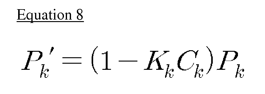
- Here, Pk' represents a corrected value of the predicted estimated error dispersion, Pk, and Kk represents a Kalman gain. In addition, Ck represents [H1 1].
- If the predicted estimated error dispersion is corrected as described above, the corrected estimated error dispersion may be input as a previous value for predicting an estimated error dispersion of a next stage. For example, Pk' of Equation 8 may be input as Pk-1 of Equation 5 and used to predict an estimated error dispersion Pk of a next stage.
- The
SOC estimation unit 140 estimates SOC of the battery by means of the state variable corrected by thecorrection unit 130. Here, the state variable corrected by thecorrection unit 130 may include SOC and overpotential. Therefore, theSOC estimation unit 140 may estimate SOC by means of the SOC corrected by thecorrection unit 130 or the overpotential corrected by thecorrection unit 130. - The
control unit 160 selects a single state variable for estimating SOC of the battery according to the current offset value measured by themeasurement unit 110. In other words, theSOC estimation unit 140 uses the corrected SOC or the corrected overpotential as a state variable in order to estimate SOC, and thecontrol unit 160 may select which state variable is used between them. - Therefore, the
control unit 160 may select one of the corrected SOC and the corrected overpotential and allow theSOC estimation unit 140 to estimate SOC of the battery by means of the selected state variable. - At this time, the
control unit 160 according to the present disclosure may determine which state variable is used to estimate SOC of the battery according to the current offset value measured by themeasurement unit 110. - For this, the
control unit 160 may compare the measured current offset value with a reference value. Here, the reference value is a current value to be compared with the measured value having a current offset and may be a predetermined value. The reference value may be a maximum value of current errors with which the current value measured by the current sensor may be regarded reliable when estimating SOC of the battery. - For example, the reference value may be 0A. In this case, the state variable for estimating SOC may be different depending on the presence of the current offset value. The reference value having a current offset may be stored in advance in a memory provided at the inside or outside of the
control unit 160. - Preferably, if the current offset value measured by the
measurement unit 110 is greater than a predetermined reference value, thecontrol unit 160 selects the overpotential as a state variable for estimating SOC. Therefore, in this case, theSOC estimation unit 140 may estimate SOC of the battery by means of the overpotential corrected by thecorrection unit 130. - For example, x2(k+1) which is a state variable in relation with the overpotential in Equation 3 may be corrected by Equation 7 and used to estimate SOC of the battery.
- In more detail, the
SOC estimation unit 140 may calculate an open circuit voltage (OCV) of the battery by means of the corrected overpotential and estimate SOC of the battery by means of the calculated OCV. Here, the relation between OCV and SOC of the battery may be stored in a storage device such as a memory provided at the inside or outside of thecontrol unit 160 in a form of a mathematical formula or table, by means of experimental measurement or the like. - The predicted and corrected SOC (x1(k)) included as a state variable is determined by means of the measured current value. However, if the current offset value is greater than the reference value, the current sensor is not reliable and thus it is inevitable that the SOC determined by means of the measured current value has many errors from the actual SOC. Therefore, according to the embodiment of the present disclosure, when the current offset value is greater than the reference value, the corrected overpotential is used as a state variable instead of the corrected SOC to estimate SOC, thereby allowing more accurate estimation of SOC. In other words, according to this embodiment, if the current offset value is greater than the reference value, SOC of the battery is estimated depending on the battery model, while the current sensor is not trusted.
- Also preferably, if the current offset value measured by the
measurement unit 110 is not greater than the reference value, thecontrol unit 160 may select SOC as a state variable for estimating SOC. Therefore, in this case, theSOC estimation unit 140 may estimate the SOC corrected by thecorrection unit 130 as SOC of the battery. - For example, a value obtained by correcting x1(k+1), predicted in Equation 3 for SOC, according to Equation 7 may be calculated as an estimated SOC value of the battery.
- If the current offset value is not greater than the reference value, the current offset is regarded negligible. Therefore, in this case, the predicted and corrected SOC included as a state variable may be intactly regarded as an estimated SOC value of the battery. In other words, if the current offset value is not greater than the reference value, the current sensor may be trusted and the SOC determined by means of the measured current value may be used as an estimated SOC value of the battery.
- As described above, the
control unit 160 may determine which state variable is used to estimate SOC. In particular, thecontrol unit 160 may determine which state variable is used, by changing a system noise component of the state equation. - For example, in Equation 3, w1(k) and w2(k) represent system noise components, and the
control unit 160 may determine which state variable is used to estimate SOC by changing w1(k) and w2(k). - At this time,
control unit 160 may determine which state variable is used to estimate SOC, by changing a ratio of the system noise component with respect to state variables in the state equation according to the measured current offset value. - For example, it is assumed that the reference value for the current offset value is 0A and the measured current offset value is 2A. At this time, since the measured current offset value is greater than the reference value, the
control unit 160 may select overpotential as a state variable for estimating SOC. For this, thecontrol unit 160 may change a ratio of w1(k) which is a system noise component with respect to the state variable x1(k) to w2(k) which is a system noise component with respect to the state variable x2(k), for SOC, namely w1(k):w2(k). - In more detail, when the current offset value is 0A, the
control unit 160 sets w1(k):w2(k) as 1:0.1, and then if the current offset value is 2A greater than the reference value, thecontrol unit 160 may change w1(k):w2(k) into 1:0.01. In other words, if the current offset value is greater than the reference value, the control unit may change a parameter w2 from 0.1 to 0.01 in the meaning that the current sensor is not trusted but the battery model is trusted. In addition, in this case, if the current offset value becomes smaller than the reference value later, the control unit may change the parameter w2 from 0.01 to 0.1 again so that the current sensor is trusted and a sensed current value may give an influence on the algorithm. - In other words, if the current offset value becomes smaller than the reference value later, the
control unit 160 increases the size of w1(k) with respect to w2(k), thereby allowing SOC to be estimated according to x1(k). - Also preferably, the
measurement unit 110 may measure a temperature of the battery. In this case, thecontrol unit 160 may change a ratio of the system noise component with respect to state variables according to the battery temperature measured by themeasurement unit 110. - At this time, more preferably, if the measured battery temperature is not higher than a predetermined temperature, the
control unit 160 may select SOC as a state variable for estimating SOC of the battery. In this case, thecontrol unit 160 may allow theSOC estimation unit 140 to estimate the corrected SOC according to Equation 7 to be estimated as SOC of the battery. - If the battery temperature is low, the reliability of battery SOC estimation using OCV or the like may deteriorate. Therefore, in this embodiment, if the battery temperature is lower than a predetermined level, the SOC predicted and corrected as a state variable may be intactly used as the estimated SOC value of the battery. In other words, if the battery temperature is not higher than a predetermined temperature, the battery model according to OCV of the battery is not trusted, but the current sensor is trusted.
- Therefore, at this time, the predetermined temperature may be experimentally determined in advance as a lowest temperature which represents a maximum error allowable when estimating SOC of the battery according to OCV. The predetermined temperature may be stored in advance in a memory provided at the inside or outside of the
control unit 160. - For example, if the predetermined temperature is determined as 0°C and the battery temperature measured by the
measurement unit 110 is 0°C or below, thecontrol unit 160 may calculate a value obtained by correcting the state variable x1(k+1) for SOC of Equation 3 according to Equation 7 as the estimated SOC value. - Preferably, the battery state estimating apparatus according to the present disclosure may further include a
SOH estimation unit 150. TheSOH estimation unit 150 may estimate a state of health (SOH) of the battery by means of the SOC estimated by theSOC estimation unit 140. - The performance of the battery such as power and capacity may degrade due to continuous use, and therefore SOH of the battery may continuously decrease. The SOH of the battery may be estimated according to the SOC of the battery, which is obvious to those skilled in the art and not described in detail here. According to the present disclosure, since SOC of the battery is estimated in consideration of a current offset and SOH of the battery is estimated according to the estimated SOC, the current offset may also be considered when estimating the SOH. Therefore, according to the embodiment of the present disclosure, SOH of the battery may be predicted more accurately in consideration of the current offset.
- Meanwhile, the battery state estimating apparatus according to the present disclosure may be implemented as being included in a battery management system (BMS) of a battery pack. In other words, the battery management system according to the present disclosure may include the battery state estimating apparatus described above. Here, the battery management system is a management device for controlling charging/discharging operations of a battery pack as a whole, and such a BMS is generally included in a battery pack protection device. In particular, the BMS may include a micro controller unit (MCU), and the
control unit 160 of the battery state estimating apparatus may be implemented using such a MCU. - In addition, the battery state estimating apparatus according to the present disclosure may be included in a vehicle. In particular, an electric vehicle, including a hybrid vehicle, supplies a driving power of a motor by using a battery, and thus it is very important to estimate a battery state such as SOC when operating the battery. Since the vehicle according to the present disclosure includes the battery state estimating apparatus described above, even though an offset of a current sensor occurs, SOC and SOH of the battery may be estimated more accurately.
-
Fig. 2 is a schematic flowchart for illustrating a method for estimating a battery state according to an embodiment of the present disclosure. InFig. 2 , a subject of each operation may be a component of the battery state estimating apparatus described above. - As shown in
Fig. 2 , the method for estimating a battery state according to the present disclosure measures a terminal voltage, a charging/discharging current and a current offset value of a battery (S110). Here, the terminal voltage, the charging/discharging current and the current offset value of a battery does not have to be measured at the same time. In particular, it is not mandatory to measure the terminal voltage or the current offset value of the battery beforeStep S 120. - Next, a state equation including SOC and overpotential of the battery as a state variable, namely a system equation, is set and a measured current value is input thereto to predict a state variable (S120). At this time, at a first stage, an initial parameter of the battery may be input as the state variable.
- In addition, a predicted state variable is input to a state equation including a terminal voltage of the battery as an output variable, namely an output equation, to predict an output variable (S130).
- Next, the output variable predicted as above is compared with the measured output variable to correct the predicted state variable (S160). In other words, the terminal voltage of the battery predicted in Step S130 is compared with the terminal voltage of the battery measured in Step S110, and the predicted state variable may be corrected according to the comparison result in Step S120.
- For this, after
Step S 130, an estimated error dispersion Pk may be predicted (S 140), and a Kalman gain Kk may be calculated as a gain factor by means of the estimated error dispersion result (S150). In addition, the Kalman gain calculated in Step S150 may be used to correct the state variable in Step S160 together with the terminal voltage predicted in Step S130 and the terminal voltage measured in Step S110. - If the state variable is corrected as described above, SOC is estimated by means of the corrected state variable (S 170). However, the corrected state variable may include a state variable in relation with SOC of the battery and a state variable in relation with overpotential of the battery, and one of these state variables may be selected to estimate SOC of the battery in Step S170. At this time, the state variable may be selected according to the current offset value measured in Step S110. In other words, in Step S170, a single state variable is selected to estimate SOC of the battery according to the current offset value of the battery, and SOC of the battery is estimated by means of the selected state variable. For example, if the current offset value measured in Step S110 is greater than the reference value, in Step S170, SOC may be estimated by means of the corrected overpotential.
- Meanwhile, the state variable corrected in Step S160 may be input as a previous value in
Step S 120 and used to predict a state variable of a next stage. - In addition, after Step S160, the estimated error dispersion may be further corrected (S180). In other words, the estimated error dispersion value predicted in Step S140 may be corrected according to the Kalman gain calculated in Step S150, and the estimated error dispersion value corrected as described above may be input as a previous value in
Step S 140 and used to predict an estimated error dispersion of a next stage. - The present disclosure has been described in detail. However, it should be understood that the detailed description and specific examples, while indicating preferred embodiments of the disclosure, are given by way of illustration only, since various changes and modifications within the spirit and scope of the disclosure will become apparent to those skilled in the art from this detailed description.
- Meanwhile, even though the term "unit" has been used in the specification, the term "unit" just represents a logic component and is not limited to a physically distinguishable component, as apparent to those skilled in the art.
Claims (15)
- An apparatus for estimating a battery state, comprising:a measurement unit for measuring a terminal voltage, a charging/discharging current and a current offset value of a battery;a prediction unit for predicting a state variable and an output variable by using a state equation which includes a state of charge (SOC) and an overpotential of the battery as state variables and includes a terminal voltage of the battery as an output variable;a correction unit for correcting the predicted state variable by comparing the predicted output variable with an output variable measured by the measurement unit;a SOC estimation unit for estimating SOC of the battery by means of the corrected state variable; anda control unit for selecting a single state variable to estimate SOC of the battery according to the measured current offset value, so that the SOC estimation unit estimates SOC of the battery by means of the selected state variable.
- The apparatus for estimating a battery state according to claim 1,
wherein when the measured current offset value is greater than a reference value, the control unit selects the overpotential as a state variable for estimating the SOC, so that the SOC estimation unit estimates SOC of the battery by means of the corrected overpotential. - The apparatus for estimating a battery state according to claim 2,
wherein the SOC estimation unit calculates an open circuit voltage (OCV) of the battery by means of the corrected overpotential and estimates SOC of the battery according to the calculated OCV. - The apparatus for estimating a battery state according to claim 2,
wherein when the measured current offset value is not greater than the reference value, the control unit selects SOC as a state variable for estimating the SOC, so that the SOC estimation unit estimates the corrected SOC as SOC of the battery. - The apparatus for estimating a battery state according to claim 1,
wherein the control unit changes a system noise component of the state equation according to the measured current offset value. - The apparatus for estimating a battery state according to claim 5,
wherein the control unit changes a ratio of the system noise component with respect to the state variables according to the measured current offset value. - The apparatus for estimating a battery state according to claim 1,
wherein the prediction unit predicts a next state variable and a next output variable by means of the state variable corrected by the correction unit as a previous value. - The apparatus for estimating a battery state according to claim 1,
wherein the measurement unit further measures a temperature of the battery, and
wherein the control unit changes a ratio of a system noise component with respect to the state variables according to the measured temperature of the battery. - The apparatus for estimating a battery state according to claim 8,
wherein when the measured temperature of the battery is not higher than a predetermined temperature, the control unit selects SOC as a state variable for estimating SOC of the battery, so that the SOC estimation unit estimates the corrected SOC as SOC of the battery. - The apparatus for estimating a battery state according to claim 1,
wherein the prediction unit predicts the state variable by using a following equation:
where x1(k+1) and x2(k+1) respectively represent SOC and overpotential of a present stage, x1(k) and x2(k) respectively represent SOC and overpotential of a previous stage, u1(k) and u2(k) respectively represent a present battery current and a previous battery current, w1(k) and w2(k) represent system noise components, A, B and C are variables in relation with battery characteristics, αekf is a variable in relation with battery capacity, and k represents a time step. - The apparatus for estimating a battery state according to claim 1,
wherein the correction unit corrects the predicted state variable by means of a gain factor, the predicted output variable and the measured output variable. - The apparatus for estimating a battery state according to claim 1, further comprising a SOH estimation unit for estimating SOH of the battery according to the SOC estimated by the SOC estimation unit.
- A battery management system, which includes the apparatus for estimating a battery state, defined in any one of the claims 1 to 12.
- A vehicle, which includes the apparatus for estimating a battery state, defined in the any one of claims 1 to 12.
- A method for estimating a battery state, comprising:measuring a terminal voltage, a charging/discharging current and a current offset value of a battery;predicting a state variable and an output variable according to a state equation which includes SOC and an overpotential of the battery as state variables and includes a terminal voltage of the battery as an output variable;correcting the predicted state variable by comparing the predicted output variable with a measured output variable; andselecting a single state variable to estimate SOC of the battery according to the measured current offset value and estimating SOC of the battery by means of the selected state variable.
Applications Claiming Priority (2)
| Application Number | Priority Date | Filing Date | Title |
|---|---|---|---|
| KR20120027284A KR101486470B1 (en) | 2012-03-16 | 2012-03-16 | Apparatus and method for estimating battery state |
| PCT/KR2013/002087 WO2013137672A1 (en) | 2012-03-16 | 2013-03-15 | Battery state estimation device and method |
Publications (3)
| Publication Number | Publication Date |
|---|---|
| EP2700966A1 true EP2700966A1 (en) | 2014-02-26 |
| EP2700966A4 EP2700966A4 (en) | 2015-11-11 |
| EP2700966B1 EP2700966B1 (en) | 2016-08-31 |
Family
ID=49161495
Family Applications (1)
| Application Number | Title | Priority Date | Filing Date |
|---|---|---|---|
| EP13761507.6A Active EP2700966B1 (en) | 2012-03-16 | 2013-03-15 | Apparatus and method for estimating battery state |
Country Status (6)
| Country | Link |
|---|---|
| US (1) | US10267864B2 (en) |
| EP (1) | EP2700966B1 (en) |
| JP (1) | JP5850142B2 (en) |
| KR (1) | KR101486470B1 (en) |
| CN (1) | CN103620432B (en) |
| WO (1) | WO2013137672A1 (en) |
Cited By (3)
| Publication number | Priority date | Publication date | Assignee | Title |
|---|---|---|---|---|
| EP3252489A4 (en) * | 2015-01-28 | 2018-01-24 | LG Chem, Ltd. | Device and method for estimating state of battery |
| EP3165934A4 (en) * | 2014-10-24 | 2018-03-28 | LG Chem, Ltd. | Apparatus for estimating charge state of secondary battery and method therefor |
| EP3588115A4 (en) * | 2017-09-07 | 2020-04-29 | LG Chem, Ltd. | DEVICE AND METHOD FOR ESTIMATING THE CHARGE OF A BATTERY |
Families Citing this family (60)
| Publication number | Priority date | Publication date | Assignee | Title |
|---|---|---|---|---|
| EP2899834B1 (en) * | 2012-09-21 | 2021-02-24 | Nissan Motor Co., Ltd | Charge state calculation device and charge state calculation method |
| KR20150024561A (en) * | 2013-08-27 | 2015-03-09 | 삼성에스디아이 주식회사 | Battery management system and driving method thereof |
| KR102079038B1 (en) * | 2013-09-30 | 2020-02-19 | 현대모비스 주식회사 | Intelligent Battery Sensor Apparatus and Method thereof |
| KR101632351B1 (en) | 2013-10-14 | 2016-06-21 | 주식회사 엘지화학 | Apparatus for estimating state of hybrid secondary battery and Method thereof |
| KR101708885B1 (en) * | 2013-10-14 | 2017-02-21 | 주식회사 엘지화학 | Apparatus for estimating state of secondary battery including blended cathode material and Method thereof |
| JP6287509B2 (en) * | 2014-04-08 | 2018-03-07 | 株式会社豊田自動織機 | Secondary battery SOC estimation apparatus and estimation method |
| KR101529515B1 (en) * | 2014-06-12 | 2015-06-17 | 국방과학연구소 | Apparatus and method for estimating battery charge state using mmae-ekf |
| EP2963434B1 (en) | 2014-06-30 | 2021-08-11 | Foundation Of Soongsil University-Industry Cooperation | Battery state estimation method and system using dual extended kalman filter, and recording medium for performing the method |
| CN104181470B (en) * | 2014-09-10 | 2017-04-26 | 山东大学 | Battery state-of-charge (SOC) estimation method based on nonlinear prediction extended Kalman filtering |
| TWI528043B (en) | 2014-10-14 | 2016-04-01 | 國立中山大學 | Battery SOC/SOH estimation circuit |
| WO2016064198A1 (en) * | 2014-10-24 | 2016-04-28 | 주식회사 엘지화학 | Apparatus for estimating charge state of secondary battery and method therefor |
| FR3029299B1 (en) * | 2014-11-28 | 2016-12-09 | Renault Sa | AUTOMATIC METHOD FOR DETERMINING THE CHARGING STATE OF A BATTERY |
| CN104460469B (en) * | 2014-12-25 | 2017-07-28 | 歌尔股份有限公司 | A kind of environmental sensor and a kind of measurement of ambient parameter and Forecasting Methodology |
| KR102338460B1 (en) | 2015-01-22 | 2021-12-13 | 삼성전자주식회사 | Method and apparatus for estimating state of battery |
| CN105068007A (en) * | 2015-07-01 | 2015-11-18 | 清华大学 | Method and system for predicting changes of parameters of lithium ion battery model |
| CN105137358B (en) * | 2015-08-27 | 2018-06-26 | 张家港莫特普数据科技有限公司 | The SOC/SOH Forecasting Methodologies of power battery based on big data self-study mechanism |
| KR102502450B1 (en) * | 2015-11-02 | 2023-02-22 | 삼성전자주식회사 | Method and apparatus of charging battery |
| CN105301511A (en) * | 2015-11-12 | 2016-02-03 | 华晨汽车集团控股有限公司 | Method for utilizing joint extended Kalman filter to pre-estimate battery state of charge |
| KR102533878B1 (en) * | 2015-12-07 | 2023-05-23 | 현대모비스 주식회사 | Method and apparatus for correcting measurement error in battery management system |
| KR102325681B1 (en) * | 2015-12-07 | 2021-11-15 | 현대모비스 주식회사 | Method and apparatus for correcting measurement error in battery management system |
| US9925888B2 (en) | 2016-03-02 | 2018-03-27 | Ford Global Technologies, Llc | Battery cell state of charge initialization in a presence of voltage measurement uncertainty |
| CN109416389B (en) * | 2016-06-28 | 2021-06-29 | 亚德诺半导体国际无限责任公司 | Wireless Sensors for Battery Systems |
| WO2018127296A1 (en) * | 2017-01-09 | 2018-07-12 | Volvo Truck Corporation | A method and arrangement for determining the state of charge of a battery pack |
| US11320491B2 (en) | 2017-03-06 | 2022-05-03 | Volvo Truck Corporation | Battery cell state of charge estimation method and a battery state monitoring system |
| KR102179677B1 (en) | 2017-04-12 | 2020-11-17 | 주식회사 엘지화학 | Apparatus and method for calculating soc |
| CN107688155B (en) * | 2017-10-19 | 2019-12-27 | 中国矿业大学 | Battery residual capacity estimation method used in battery management system |
| KR102239365B1 (en) | 2017-10-20 | 2021-04-09 | 주식회사 엘지화학 | Apparatus for estimating state of charge of battery |
| KR102203245B1 (en) * | 2017-11-01 | 2021-01-13 | 주식회사 엘지화학 | Apparatus and method for estimating SOC of battery |
| KR102437477B1 (en) * | 2017-12-26 | 2022-08-26 | 주식회사 엘지에너지솔루션 | Battery management system and method for calculating a full charge capacity of a battery |
| CN109991552B (en) * | 2017-12-29 | 2021-01-15 | 微宏动力系统(湖州)有限公司 | A method for estimating the remaining capacity of a battery |
| KR102398073B1 (en) * | 2018-01-09 | 2022-05-12 | 주식회사 엘지에너지솔루션 | Apparatus and method for correcting state of charge in battery |
| KR102458526B1 (en) * | 2018-02-07 | 2022-10-25 | 주식회사 엘지에너지솔루션 | Apparatus and method for estimating soc base on operating state of battery |
| KR102349235B1 (en) * | 2018-02-14 | 2022-01-07 | 주식회사 엘지에너지솔루션 | Apparatus and method for estimating state of charge for battery |
| JP6978339B2 (en) * | 2018-02-16 | 2021-12-08 | 株式会社半導体エネルギー研究所 | Secondary battery charge status estimation device and abnormality detection device, and secondary battery management system |
| KR102429307B1 (en) * | 2018-02-19 | 2022-08-03 | 주식회사 엘지에너지솔루션 | Apparatus for estimating state of secondary battery |
| KR102783337B1 (en) | 2018-02-20 | 2025-03-19 | 주식회사 엘지에너지솔루션 | Apparatus and method for calculating State Of Charge |
| CN108448665A (en) * | 2018-03-08 | 2018-08-24 | 合肥新胜电达电子科技有限公司 | A kind of intelligent charging system that accumulator group is charged and conserved |
| KR102650965B1 (en) | 2018-04-23 | 2024-03-25 | 삼성에스디아이 주식회사 | Method of estimating battery states |
| KR101944313B1 (en) * | 2018-04-30 | 2019-02-01 | 쌍용자동차 주식회사 | Battery life prediction apparatus |
| KR102318754B1 (en) * | 2018-05-18 | 2021-10-27 | 엘에스일렉트릭(주) | Optimal control Method of DC-DC Converter |
| JP7091999B2 (en) * | 2018-11-09 | 2022-06-28 | トヨタ自動車株式会社 | Battery control device |
| CN109725188B (en) * | 2018-12-29 | 2021-10-01 | 蜂巢能源科技有限公司 | A current measurement method and device |
| CN109633477B (en) * | 2019-01-04 | 2021-04-16 | 深圳市计量质量检测研究院 | Real-time monitoring method of battery pack health status based on EKF-GPR and daily fragment data |
| US11391781B2 (en) | 2019-02-15 | 2022-07-19 | Lg Energy Solution, Ltd. | SOC estimating apparatus and method |
| KR102859090B1 (en) * | 2019-03-07 | 2025-09-12 | 주식회사 엘지에너지솔루션 | Battery state of health estimation method and battery pack using the same |
| WO2021040306A1 (en) * | 2019-08-23 | 2021-03-04 | 주식회사 엘지화학 | Method for predicting soh of battery and battery pack employing same |
| KR102821614B1 (en) * | 2019-10-29 | 2025-06-16 | 주식회사 엘지에너지솔루션 | Soc estimation method and baterry system using the same |
| KR102824433B1 (en) * | 2019-10-31 | 2025-06-23 | 주식회사 엘지에너지솔루션 | Method for estimating of battery's state of charge and Battery Management System |
| US11397214B2 (en) * | 2020-01-17 | 2022-07-26 | Semiconductor Components Industries, Llc | Methods and apparatus for a battery |
| KR102856837B1 (en) * | 2020-03-23 | 2025-09-05 | 주식회사 엘지에너지솔루션 | Apparatus and method for setting battery parameter |
| JP7499591B2 (en) * | 2020-03-25 | 2024-06-14 | エナジーウィズ株式会社 | BATTERY STATE ESTIMATION DEVICE AND BATTERY STATE ESTIMATION METHOD |
| CN111474481B (en) * | 2020-04-13 | 2022-08-09 | 深圳埃瑞斯瓦特新能源有限公司 | Battery SOC estimation method and device based on extended Kalman filtering algorithm |
| JP7485566B2 (en) * | 2020-08-12 | 2024-05-16 | 日立グローバルライフソリューションズ株式会社 | BATTERY STATE ESTIMATION DEVICE, BATTERY STATE ESTIMATION METHOD, AND PROGRAM |
| KR20220100469A (en) | 2021-01-08 | 2022-07-15 | 주식회사 엘지에너지솔루션 | Battery management apparatus and method of the same |
| US11801768B2 (en) | 2021-05-05 | 2023-10-31 | Toyota Motor North America, Inc. | Transport battery health |
| KR102885238B1 (en) | 2021-09-08 | 2025-11-12 | 삼성전자주식회사 | Electronic device for estimating battery state and method for operating method thereof |
| KR102878315B1 (en) * | 2022-01-04 | 2025-10-28 | 주식회사 엘지에너지솔루션 | Apparatus and method for estimating state of battery |
| KR102416009B1 (en) * | 2022-02-10 | 2022-06-30 | 이중휘 | Apparatus and method for estimating soc of battery |
| KR102412606B1 (en) * | 2022-02-10 | 2022-06-22 | 이중휘 | Apparatus and method for estimating soh of battery |
| KR20250114770A (en) * | 2024-01-22 | 2025-07-29 | 주식회사 배러머신 | Method and apparatus for generating safe deep neural network model for safely predicting battery status |
Family Cites Families (26)
| Publication number | Priority date | Publication date | Assignee | Title |
|---|---|---|---|---|
| JPH07274411A (en) * | 1994-03-30 | 1995-10-20 | Mitsubishi Electric Corp | Vehicle power generation control device |
| US6621250B1 (en) | 1999-09-09 | 2003-09-16 | Toyota Jidosha Kabushiki Kaisha | Battery capacity measuring and remaining capacity calculating system |
| JP2002238181A (en) * | 2001-02-13 | 2002-08-23 | Denso Corp | In-vehicle battery charge state detection device |
| JP4071207B2 (en) * | 2004-03-12 | 2008-04-02 | 株式会社日本自動車部品総合研究所 | Battery current measuring device |
| JP4830382B2 (en) * | 2005-07-19 | 2011-12-07 | 日産自動車株式会社 | Secondary battery charge rate estimation device |
| JP4923462B2 (en) * | 2005-07-25 | 2012-04-25 | 日産自動車株式会社 | Secondary battery charge rate estimation device |
| JP2007057399A (en) * | 2005-08-25 | 2007-03-08 | Nissan Motor Co Ltd | Output correction device for current sensor |
| KR100740106B1 (en) * | 2005-09-12 | 2007-07-16 | 삼성에스디아이 주식회사 | Battery Management System and Its Driving Method |
| JP4984527B2 (en) * | 2005-12-27 | 2012-07-25 | トヨタ自動車株式会社 | Secondary battery charge state estimation device and charge state estimation method |
| US7400115B2 (en) * | 2006-02-09 | 2008-07-15 | Lg Chem, Ltd. | System, method, and article of manufacture for determining an estimated combined battery state-parameter vector |
| KR100804698B1 (en) | 2006-06-26 | 2008-02-18 | 삼성에스디아이 주식회사 | The method of assuming the state of charge of the battery, battery management system using the method and the driving method of the battery management system using the method |
| KR100861232B1 (en) * | 2006-12-12 | 2008-10-02 | 넥스콘 테크놀러지 주식회사 | Battery residual capacity correction method of hybrid electric vehicle |
| KR100878123B1 (en) * | 2007-05-14 | 2009-01-12 | 주식회사 엘지화학 | Method and system for battery state and parameter estimation |
| JP4893653B2 (en) * | 2008-02-19 | 2012-03-07 | トヨタ自動車株式会社 | Vehicle, rechargeable battery state of charge estimation method and vehicle control method |
| KR101065591B1 (en) * | 2008-12-30 | 2011-09-20 | 한국전기연구원 | Battery management system and method for estimating battery charge state |
| JP2010203854A (en) * | 2009-03-02 | 2010-09-16 | Nissan Motor Co Ltd | Device of estimating internal state of secondary battery |
| JP2011106952A (en) * | 2009-11-17 | 2011-06-02 | Honda Motor Co Ltd | Method for estimating residual capacity of battery |
| JP4689755B1 (en) * | 2010-03-23 | 2011-05-25 | 古河電気工業株式会社 | Battery internal state estimation device and battery internal state estimation method |
| WO2011122310A1 (en) * | 2010-03-30 | 2011-10-06 | 本田技研工業株式会社 | Method for detecting battery capacity of secondary battery |
| JP5640477B2 (en) * | 2010-06-08 | 2014-12-17 | マツダ株式会社 | Battery remaining capacity detection method and detection apparatus |
| KR20120004670A (en) * | 2010-07-07 | 2012-01-13 | 인셀스(주) | Car battery sensor |
| JP5393619B2 (en) * | 2010-08-26 | 2014-01-22 | カルソニックカンセイ株式会社 | Battery charge rate estimation device |
| JP5329500B2 (en) * | 2010-09-06 | 2013-10-30 | カルソニックカンセイ株式会社 | Battery charge rate estimation device |
| JP5419832B2 (en) * | 2010-09-07 | 2014-02-19 | カルソニックカンセイ株式会社 | Battery capacity calculation device and battery capacity calculation method |
| US9201121B2 (en) * | 2010-12-06 | 2015-12-01 | Texas Instruments Incorporated | System and method for sensing battery capacity |
| EP2761317A2 (en) * | 2011-09-30 | 2014-08-06 | KPIT Technologies Limited | A system and method for determining state of charge of a battery |
-
2012
- 2012-03-16 KR KR20120027284A patent/KR101486470B1/en active Active
-
2013
- 2013-03-15 EP EP13761507.6A patent/EP2700966B1/en active Active
- 2013-03-15 JP JP2014512778A patent/JP5850142B2/en active Active
- 2013-03-15 WO PCT/KR2013/002087 patent/WO2013137672A1/en not_active Ceased
- 2013-03-15 CN CN201380001829.7A patent/CN103620432B/en active Active
- 2013-11-15 US US14/081,711 patent/US10267864B2/en active Active
Cited By (4)
| Publication number | Priority date | Publication date | Assignee | Title |
|---|---|---|---|---|
| EP3165934A4 (en) * | 2014-10-24 | 2018-03-28 | LG Chem, Ltd. | Apparatus for estimating charge state of secondary battery and method therefor |
| EP3252489A4 (en) * | 2015-01-28 | 2018-01-24 | LG Chem, Ltd. | Device and method for estimating state of battery |
| EP3588115A4 (en) * | 2017-09-07 | 2020-04-29 | LG Chem, Ltd. | DEVICE AND METHOD FOR ESTIMATING THE CHARGE OF A BATTERY |
| US11231466B2 (en) | 2017-09-07 | 2022-01-25 | Lg Energy Solution, Ltd. | Apparatus and method for estimating a state of charge of a battery |
Also Published As
| Publication number | Publication date |
|---|---|
| US10267864B2 (en) | 2019-04-23 |
| KR101486470B1 (en) | 2015-01-26 |
| CN103620432A (en) | 2014-03-05 |
| EP2700966B1 (en) | 2016-08-31 |
| US20140074416A1 (en) | 2014-03-13 |
| CN103620432B (en) | 2016-05-18 |
| KR20130105123A (en) | 2013-09-25 |
| JP5850142B2 (en) | 2016-02-03 |
| JP2014522488A (en) | 2014-09-04 |
| EP2700966A4 (en) | 2015-11-11 |
| WO2013137672A1 (en) | 2013-09-19 |
Similar Documents
| Publication | Publication Date | Title |
|---|---|---|
| US10267864B2 (en) | Battery management system including apparatus for estimating battery state | |
| EP3605127B1 (en) | Device and method for estimating battery resistance | |
| US8004243B2 (en) | Battery capacity estimating method and apparatus | |
| US11391779B2 (en) | Battery capacity estimation apparatus and method, and battery management apparatus provided with same and method thereof | |
| EP2321663B1 (en) | Apparatus and method for estimating state of health of battery based on battery voltage variation pattern | |
| EP3076518B1 (en) | Power storage system and method for charging secondary cell | |
| KR101983392B1 (en) | Apparatus and Method for estimating the battery SOC | |
| JP7231657B2 (en) | battery controller | |
| KR101702868B1 (en) | Method for determining the capacity of a battery cell | |
| JP4864383B2 (en) | Deterioration state estimation device for power storage device | |
| EP2442126A2 (en) | Battery management system and method of estimating battery state of charge | |
| US11187755B2 (en) | Apparatus and method for estimating SOC of battery | |
| CN102576055A (en) | Method for Determining and/or Predicting Maximum Capacity of a Battery | |
| JP6577990B2 (en) | Internal state estimation device | |
| CN105938181A (en) | Electric power storage element management apparatus, electric power storage element management method, electric power storage element management program, electric power storage element module and movable body | |
| JP2019049412A (en) | Battery pack state estimation device | |
| KR101498764B1 (en) | Method and apparatus for battery resistance estimation, and battery management system using the same | |
| WO2020085011A1 (en) | Battery control device | |
| KR102688034B1 (en) | Apparatus and method for estimating charging time of secondary battery | |
| CN104204831A (en) | Method for determining a maximum available constant current of a battery, arrangement for carrying out said method, battery combined with said type of arrangement and motor vehicle comprising said type of battery | |
| US20230314516A1 (en) | Discharge voltage graph prediction method and battery system using the same | |
| JPWO2020085097A1 (en) | Battery control device | |
| JP5886225B2 (en) | Battery control device and battery control method | |
| KR102375843B1 (en) | Apparatus and method for managing battery | |
| KR101584755B1 (en) | Apparatus and method for predicting output voltage for battery |
Legal Events
| Date | Code | Title | Description |
|---|---|---|---|
| PUAI | Public reference made under article 153(3) epc to a published international application that has entered the european phase |
Free format text: ORIGINAL CODE: 0009012 |
|
| 17P | Request for examination filed |
Effective date: 20131119 |
|
| AK | Designated contracting states |
Kind code of ref document: A1 Designated state(s): AL AT BE BG CH CY CZ DE DK EE ES FI FR GB GR HR HU IE IS IT LI LT LU LV MC MK MT NL NO PL PT RO RS SE SI SK SM TR |
|
| DAX | Request for extension of the european patent (deleted) | ||
| RA4 | Supplementary search report drawn up and despatched (corrected) |
Effective date: 20151014 |
|
| RIC1 | Information provided on ipc code assigned before grant |
Ipc: G01R 19/165 20060101ALI20151008BHEP Ipc: G01R 31/36 20060101AFI20151008BHEP |
|
| GRAP | Despatch of communication of intention to grant a patent |
Free format text: ORIGINAL CODE: EPIDOSNIGR1 |
|
| INTG | Intention to grant announced |
Effective date: 20160613 |
|
| GRAJ | Information related to disapproval of communication of intention to grant by the applicant or resumption of examination proceedings by the epo deleted |
Free format text: ORIGINAL CODE: EPIDOSDIGR1 |
|
| GRAS | Grant fee paid |
Free format text: ORIGINAL CODE: EPIDOSNIGR3 |
|
| GRAA | (expected) grant |
Free format text: ORIGINAL CODE: 0009210 |
|
| INTG | Intention to grant announced |
Effective date: 20160613 |
|
| RAP1 | Party data changed (applicant data changed or rights of an application transferred) |
Owner name: LG CHEM, LTD. |
|
| RIN1 | Information on inventor provided before grant (corrected) |
Inventor name: KIM, CHEOL-TAEK Inventor name: PARK, KYU-HA |
|
| AK | Designated contracting states |
Kind code of ref document: B1 Designated state(s): AL AT BE BG CH CY CZ DE DK EE ES FI FR GB GR HR HU IE IS IT LI LT LU LV MC MK MT NL NO PL PT RO RS SE SI SK SM TR |
|
| REG | Reference to a national code |
Ref country code: CH Ref legal event code: EP Ref country code: GB Ref legal event code: FG4D |
|
| REG | Reference to a national code |
Ref country code: IE Ref legal event code: FG4D |
|
| REG | Reference to a national code |
Ref country code: DE Ref legal event code: R096 Ref document number: 602013010936 Country of ref document: DE |
|
| REG | Reference to a national code |
Ref country code: AT Ref legal event code: REF Ref document number: 825440 Country of ref document: AT Kind code of ref document: T Effective date: 20161015 |
|
| REG | Reference to a national code |
Ref country code: LT Ref legal event code: MG4D |
|
| REG | Reference to a national code |
Ref country code: NL Ref legal event code: MP Effective date: 20160831 |
|
| REG | Reference to a national code |
Ref country code: AT Ref legal event code: MK05 Ref document number: 825440 Country of ref document: AT Kind code of ref document: T Effective date: 20160831 |
|
| PG25 | Lapsed in a contracting state [announced via postgrant information from national office to epo] |
Ref country code: LT Free format text: LAPSE BECAUSE OF FAILURE TO SUBMIT A TRANSLATION OF THE DESCRIPTION OR TO PAY THE FEE WITHIN THE PRESCRIBED TIME-LIMIT Effective date: 20160831 Ref country code: HR Free format text: LAPSE BECAUSE OF FAILURE TO SUBMIT A TRANSLATION OF THE DESCRIPTION OR TO PAY THE FEE WITHIN THE PRESCRIBED TIME-LIMIT Effective date: 20160831 Ref country code: NO Free format text: LAPSE BECAUSE OF FAILURE TO SUBMIT A TRANSLATION OF THE DESCRIPTION OR TO PAY THE FEE WITHIN THE PRESCRIBED TIME-LIMIT Effective date: 20161130 Ref country code: RS Free format text: LAPSE BECAUSE OF FAILURE TO SUBMIT A TRANSLATION OF THE DESCRIPTION OR TO PAY THE FEE WITHIN THE PRESCRIBED TIME-LIMIT Effective date: 20160831 Ref country code: FI Free format text: LAPSE BECAUSE OF FAILURE TO SUBMIT A TRANSLATION OF THE DESCRIPTION OR TO PAY THE FEE WITHIN THE PRESCRIBED TIME-LIMIT Effective date: 20160831 |
|
| REG | Reference to a national code |
Ref country code: FR Ref legal event code: PLFP Year of fee payment: 5 |
|
| PG25 | Lapsed in a contracting state [announced via postgrant information from national office to epo] |
Ref country code: LV Free format text: LAPSE BECAUSE OF FAILURE TO SUBMIT A TRANSLATION OF THE DESCRIPTION OR TO PAY THE FEE WITHIN THE PRESCRIBED TIME-LIMIT Effective date: 20160831 Ref country code: SE Free format text: LAPSE BECAUSE OF FAILURE TO SUBMIT A TRANSLATION OF THE DESCRIPTION OR TO PAY THE FEE WITHIN THE PRESCRIBED TIME-LIMIT Effective date: 20160831 Ref country code: ES Free format text: LAPSE BECAUSE OF FAILURE TO SUBMIT A TRANSLATION OF THE DESCRIPTION OR TO PAY THE FEE WITHIN THE PRESCRIBED TIME-LIMIT Effective date: 20160831 Ref country code: GR Free format text: LAPSE BECAUSE OF FAILURE TO SUBMIT A TRANSLATION OF THE DESCRIPTION OR TO PAY THE FEE WITHIN THE PRESCRIBED TIME-LIMIT Effective date: 20161201 Ref country code: AT Free format text: LAPSE BECAUSE OF FAILURE TO SUBMIT A TRANSLATION OF THE DESCRIPTION OR TO PAY THE FEE WITHIN THE PRESCRIBED TIME-LIMIT Effective date: 20160831 Ref country code: NL Free format text: LAPSE BECAUSE OF FAILURE TO SUBMIT A TRANSLATION OF THE DESCRIPTION OR TO PAY THE FEE WITHIN THE PRESCRIBED TIME-LIMIT Effective date: 20160831 |
|
| PG25 | Lapsed in a contracting state [announced via postgrant information from national office to epo] |
Ref country code: RO Free format text: LAPSE BECAUSE OF FAILURE TO SUBMIT A TRANSLATION OF THE DESCRIPTION OR TO PAY THE FEE WITHIN THE PRESCRIBED TIME-LIMIT Effective date: 20160831 Ref country code: EE Free format text: LAPSE BECAUSE OF FAILURE TO SUBMIT A TRANSLATION OF THE DESCRIPTION OR TO PAY THE FEE WITHIN THE PRESCRIBED TIME-LIMIT Effective date: 20160831 |
|
| PG25 | Lapsed in a contracting state [announced via postgrant information from national office to epo] |
Ref country code: PL Free format text: LAPSE BECAUSE OF FAILURE TO SUBMIT A TRANSLATION OF THE DESCRIPTION OR TO PAY THE FEE WITHIN THE PRESCRIBED TIME-LIMIT Effective date: 20160831 Ref country code: CZ Free format text: LAPSE BECAUSE OF FAILURE TO SUBMIT A TRANSLATION OF THE DESCRIPTION OR TO PAY THE FEE WITHIN THE PRESCRIBED TIME-LIMIT Effective date: 20160831 Ref country code: SM Free format text: LAPSE BECAUSE OF FAILURE TO SUBMIT A TRANSLATION OF THE DESCRIPTION OR TO PAY THE FEE WITHIN THE PRESCRIBED TIME-LIMIT Effective date: 20160831 Ref country code: DK Free format text: LAPSE BECAUSE OF FAILURE TO SUBMIT A TRANSLATION OF THE DESCRIPTION OR TO PAY THE FEE WITHIN THE PRESCRIBED TIME-LIMIT Effective date: 20160831 Ref country code: BE Free format text: LAPSE BECAUSE OF FAILURE TO SUBMIT A TRANSLATION OF THE DESCRIPTION OR TO PAY THE FEE WITHIN THE PRESCRIBED TIME-LIMIT Effective date: 20160831 Ref country code: SK Free format text: LAPSE BECAUSE OF FAILURE TO SUBMIT A TRANSLATION OF THE DESCRIPTION OR TO PAY THE FEE WITHIN THE PRESCRIBED TIME-LIMIT Effective date: 20160831 Ref country code: BG Free format text: LAPSE BECAUSE OF FAILURE TO SUBMIT A TRANSLATION OF THE DESCRIPTION OR TO PAY THE FEE WITHIN THE PRESCRIBED TIME-LIMIT Effective date: 20161130 Ref country code: PT Free format text: LAPSE BECAUSE OF FAILURE TO SUBMIT A TRANSLATION OF THE DESCRIPTION OR TO PAY THE FEE WITHIN THE PRESCRIBED TIME-LIMIT Effective date: 20170102 |
|
| REG | Reference to a national code |
Ref country code: DE Ref legal event code: R097 Ref document number: 602013010936 Country of ref document: DE |
|
| PG25 | Lapsed in a contracting state [announced via postgrant information from national office to epo] |
Ref country code: IT Free format text: LAPSE BECAUSE OF FAILURE TO SUBMIT A TRANSLATION OF THE DESCRIPTION OR TO PAY THE FEE WITHIN THE PRESCRIBED TIME-LIMIT Effective date: 20160831 |
|
| PLBE | No opposition filed within time limit |
Free format text: ORIGINAL CODE: 0009261 |
|
| STAA | Information on the status of an ep patent application or granted ep patent |
Free format text: STATUS: NO OPPOSITION FILED WITHIN TIME LIMIT |
|
| 26N | No opposition filed |
Effective date: 20170601 |
|
| PG25 | Lapsed in a contracting state [announced via postgrant information from national office to epo] |
Ref country code: SI Free format text: LAPSE BECAUSE OF FAILURE TO SUBMIT A TRANSLATION OF THE DESCRIPTION OR TO PAY THE FEE WITHIN THE PRESCRIBED TIME-LIMIT Effective date: 20160831 |
|
| REG | Reference to a national code |
Ref country code: CH Ref legal event code: PL |
|
| PG25 | Lapsed in a contracting state [announced via postgrant information from national office to epo] |
Ref country code: MC Free format text: LAPSE BECAUSE OF FAILURE TO SUBMIT A TRANSLATION OF THE DESCRIPTION OR TO PAY THE FEE WITHIN THE PRESCRIBED TIME-LIMIT Effective date: 20160831 |
|
| REG | Reference to a national code |
Ref country code: IE Ref legal event code: MM4A |
|
| PG25 | Lapsed in a contracting state [announced via postgrant information from national office to epo] |
Ref country code: LU Free format text: LAPSE BECAUSE OF NON-PAYMENT OF DUE FEES Effective date: 20170315 |
|
| REG | Reference to a national code |
Ref country code: FR Ref legal event code: PLFP Year of fee payment: 6 |
|
| PG25 | Lapsed in a contracting state [announced via postgrant information from national office to epo] |
Ref country code: CH Free format text: LAPSE BECAUSE OF NON-PAYMENT OF DUE FEES Effective date: 20170331 Ref country code: IE Free format text: LAPSE BECAUSE OF NON-PAYMENT OF DUE FEES Effective date: 20170315 Ref country code: LI Free format text: LAPSE BECAUSE OF NON-PAYMENT OF DUE FEES Effective date: 20170331 |
|
| PG25 | Lapsed in a contracting state [announced via postgrant information from national office to epo] |
Ref country code: MT Free format text: LAPSE BECAUSE OF NON-PAYMENT OF DUE FEES Effective date: 20170315 |
|
| PG25 | Lapsed in a contracting state [announced via postgrant information from national office to epo] |
Ref country code: AL Free format text: LAPSE BECAUSE OF FAILURE TO SUBMIT A TRANSLATION OF THE DESCRIPTION OR TO PAY THE FEE WITHIN THE PRESCRIBED TIME-LIMIT Effective date: 20160831 |
|
| PG25 | Lapsed in a contracting state [announced via postgrant information from national office to epo] |
Ref country code: HU Free format text: LAPSE BECAUSE OF FAILURE TO SUBMIT A TRANSLATION OF THE DESCRIPTION OR TO PAY THE FEE WITHIN THE PRESCRIBED TIME-LIMIT; INVALID AB INITIO Effective date: 20130315 |
|
| PG25 | Lapsed in a contracting state [announced via postgrant information from national office to epo] |
Ref country code: CY Free format text: LAPSE BECAUSE OF NON-PAYMENT OF DUE FEES Effective date: 20160831 |
|
| PG25 | Lapsed in a contracting state [announced via postgrant information from national office to epo] |
Ref country code: MK Free format text: LAPSE BECAUSE OF FAILURE TO SUBMIT A TRANSLATION OF THE DESCRIPTION OR TO PAY THE FEE WITHIN THE PRESCRIBED TIME-LIMIT Effective date: 20160831 |
|
| PG25 | Lapsed in a contracting state [announced via postgrant information from national office to epo] |
Ref country code: TR Free format text: LAPSE BECAUSE OF FAILURE TO SUBMIT A TRANSLATION OF THE DESCRIPTION OR TO PAY THE FEE WITHIN THE PRESCRIBED TIME-LIMIT Effective date: 20160831 |
|
| PG25 | Lapsed in a contracting state [announced via postgrant information from national office to epo] |
Ref country code: IS Free format text: LAPSE BECAUSE OF FAILURE TO SUBMIT A TRANSLATION OF THE DESCRIPTION OR TO PAY THE FEE WITHIN THE PRESCRIBED TIME-LIMIT Effective date: 20161231 |
|
| REG | Reference to a national code |
Ref country code: DE Ref legal event code: R081 Ref document number: 602013010936 Country of ref document: DE Owner name: LG ENERGY SOLUTION LTD., KR Free format text: FORMER OWNER: LG CHEM. LTD., SEOUL, KR Ref country code: DE Ref legal event code: R081 Ref document number: 602013010936 Country of ref document: DE Owner name: LG ENERGY SOLUTION, LTD., KR Free format text: FORMER OWNER: LG CHEM. LTD., SEOUL, KR |
|
| P01 | Opt-out of the competence of the unified patent court (upc) registered |
Effective date: 20230512 |
|
| REG | Reference to a national code |
Ref country code: GB Ref legal event code: 732E Free format text: REGISTERED BETWEEN 20230824 AND 20230831 |
|
| REG | Reference to a national code |
Ref country code: DE Ref legal event code: R081 Ref document number: 602013010936 Country of ref document: DE Owner name: LG ENERGY SOLUTION, LTD., KR Free format text: FORMER OWNER: LG ENERGY SOLUTION LTD., SEOUL, KR |
|
| PGFP | Annual fee paid to national office [announced via postgrant information from national office to epo] |
Ref country code: GB Payment date: 20260224 Year of fee payment: 14 |
|
| PGFP | Annual fee paid to national office [announced via postgrant information from national office to epo] |
Ref country code: DE Payment date: 20260220 Year of fee payment: 14 |
|
| PGFP | Annual fee paid to national office [announced via postgrant information from national office to epo] |
Ref country code: FR Payment date: 20260224 Year of fee payment: 14 |