EP2700844A1 - Engagement chain unit - Google Patents
Engagement chain unit Download PDFInfo
- Publication number
- EP2700844A1 EP2700844A1 EP12774681.6A EP12774681A EP2700844A1 EP 2700844 A1 EP2700844 A1 EP 2700844A1 EP 12774681 A EP12774681 A EP 12774681A EP 2700844 A1 EP2700844 A1 EP 2700844A1
- Authority
- EP
- European Patent Office
- Prior art keywords
- interlocking
- chain
- tooth plates
- pair
- chains
- Prior art date
- Legal status (The legal status is an assumption and is not a legal conclusion. Google has not performed a legal analysis and makes no representation as to the accuracy of the status listed.)
- Granted
Links
Images



Classifications
-
- F—MECHANICAL ENGINEERING; LIGHTING; HEATING; WEAPONS; BLASTING
- F16—ENGINEERING ELEMENTS AND UNITS; GENERAL MEASURES FOR PRODUCING AND MAINTAINING EFFECTIVE FUNCTIONING OF MACHINES OR INSTALLATIONS; THERMAL INSULATION IN GENERAL
- F16H—GEARING
- F16H19/00—Gearings comprising essentially only toothed gears or friction members and not capable of conveying indefinitely-continuing rotary motion
- F16H19/02—Gearings comprising essentially only toothed gears or friction members and not capable of conveying indefinitely-continuing rotary motion for interconverting rotary or oscillating motion and reciprocating motion
-
- F—MECHANICAL ENGINEERING; LIGHTING; HEATING; WEAPONS; BLASTING
- F16—ENGINEERING ELEMENTS AND UNITS; GENERAL MEASURES FOR PRODUCING AND MAINTAINING EFFECTIVE FUNCTIONING OF MACHINES OR INSTALLATIONS; THERMAL INSULATION IN GENERAL
- F16G—BELTS, CABLES, OR ROPES, PREDOMINANTLY USED FOR DRIVING PURPOSES; CHAINS; FITTINGS PREDOMINANTLY USED THEREFOR
- F16G13/00—Chains
- F16G13/02—Driving-chains
- F16G13/04—Toothed chains
-
- B—PERFORMING OPERATIONS; TRANSPORTING
- B66—HOISTING; LIFTING; HAULING
- B66F—HOISTING, LIFTING, HAULING OR PUSHING, NOT OTHERWISE PROVIDED FOR, e.g. DEVICES WHICH APPLY A LIFTING OR PUSHING FORCE DIRECTLY TO THE SURFACE OF A LOAD
- B66F3/00—Devices, e.g. jacks, adapted for uninterrupted lifting of loads
- B66F3/02—Devices, e.g. jacks, adapted for uninterrupted lifting of loads with racks actuated by pinions
- B66F3/06—Devices, e.g. jacks, adapted for uninterrupted lifting of loads with racks actuated by pinions with racks comprising pivotable toothed sections or segments, e.g. arranged in pairs
-
- F—MECHANICAL ENGINEERING; LIGHTING; HEATING; WEAPONS; BLASTING
- F16—ENGINEERING ELEMENTS AND UNITS; GENERAL MEASURES FOR PRODUCING AND MAINTAINING EFFECTIVE FUNCTIONING OF MACHINES OR INSTALLATIONS; THERMAL INSULATION IN GENERAL
- F16G—BELTS, CABLES, OR ROPES, PREDOMINANTLY USED FOR DRIVING PURPOSES; CHAINS; FITTINGS PREDOMINANTLY USED THEREFOR
- F16G13/00—Chains
- F16G13/18—Chains having special overall characteristics
- F16G13/20—Chains having special overall characteristics stiff; Push-pull chains
-
- F—MECHANICAL ENGINEERING; LIGHTING; HEATING; WEAPONS; BLASTING
- F16—ENGINEERING ELEMENTS AND UNITS; GENERAL MEASURES FOR PRODUCING AND MAINTAINING EFFECTIVE FUNCTIONING OF MACHINES OR INSTALLATIONS; THERMAL INSULATION IN GENERAL
- F16H—GEARING
- F16H19/00—Gearings comprising essentially only toothed gears or friction members and not capable of conveying indefinitely-continuing rotary motion
- F16H19/02—Gearings comprising essentially only toothed gears or friction members and not capable of conveying indefinitely-continuing rotary motion for interconverting rotary or oscillating motion and reciprocating motion
- F16H19/06—Gearings comprising essentially only toothed gears or friction members and not capable of conveying indefinitely-continuing rotary motion for interconverting rotary or oscillating motion and reciprocating motion comprising flexible members, e.g. an endless flexible member
- F16H19/0636—Gearings comprising essentially only toothed gears or friction members and not capable of conveying indefinitely-continuing rotary motion for interconverting rotary or oscillating motion and reciprocating motion comprising flexible members, e.g. an endless flexible member the flexible member being a non-buckling chain
-
- F—MECHANICAL ENGINEERING; LIGHTING; HEATING; WEAPONS; BLASTING
- F16—ENGINEERING ELEMENTS AND UNITS; GENERAL MEASURES FOR PRODUCING AND MAINTAINING EFFECTIVE FUNCTIONING OF MACHINES OR INSTALLATIONS; THERMAL INSULATION IN GENERAL
- F16H—GEARING
- F16H55/00—Elements with teeth or friction surfaces for conveying motion; Worms, pulleys or sheaves for gearing mechanisms
- F16H55/02—Toothed members; Worms
- F16H55/30—Chain-wheels
-
- Y—GENERAL TAGGING OF NEW TECHNOLOGICAL DEVELOPMENTS; GENERAL TAGGING OF CROSS-SECTIONAL TECHNOLOGIES SPANNING OVER SEVERAL SECTIONS OF THE IPC; TECHNICAL SUBJECTS COVERED BY FORMER USPC CROSS-REFERENCE ART COLLECTIONS [XRACs] AND DIGESTS
- Y10—TECHNICAL SUBJECTS COVERED BY FORMER USPC
- Y10T—TECHNICAL SUBJECTS COVERED BY FORMER US CLASSIFICATION
- Y10T74/00—Machine element or mechanism
- Y10T74/18—Mechanical movements
- Y10T74/18056—Rotary to or from reciprocating or oscillating
- Y10T74/18088—Rack and pinion type
- Y10T74/18096—Shifting rack
Definitions
- the present invention relates to an interlocking chain unit used in manufacturing facilities in various manufacturing fields, transportation facilities in the transportation field, nursing care facilities in medical and welfare fields, and stage facilities in art fields, and moving a driven body forward and backward.
- a drive unit As a drive unit, a drive unit is known that moves a driven object such as a heavy object by using a pair of interlocking chains, which are also referred to as zip chains. Specifically, the pair of interlocking chains are interlocked with each other and integrally driven (for example, refer to Patent Document 1).
- a silent chain transmission device has known in which noise and vibrations caused in driving of chains are suppressed by defining shapes of faces of link plates to be interlocked with inner flanks, i.e., sprocket teeth (for example, refer to Patent Document 2).
- an object of the invention is to provide an interlocking chain unit in which inner tooth plates and outer tooth plates are reliably and firmly interlocked with each other and rigidity of the pair of interlocking chains, which are interlocked and integrated with each other, is increased to thereby avoid buckling and twisting of the rigidified chain portion.
- the invention according to claim 1 provides an interlocking chain unit comprising a pair of interlocking chains.
- Each interlocking chain is formed by connecting, with pairs of front and rear coupling pins, a large number of inner tooth plates and a large number of outer tooth plates in a chain longitudinal direction.
- the outer tooth plates are arranged to be adjacent to outer sides of the inner tooth plates and have partial overlap regions with the inner tooth plates.
- the interlocking chains are configured to become interlocked with each other to integrally become rigid in a rigid chain forward and backward movement direction and to become disengaged from each other to bifurcate.
- hook-shaped interlocking end faces of the two inner tooth plates interlocked with each other form plate overlap regions when the pair of interlocking chains are seen in a plate normal direction, which is orthogonal to plate main faces of the inner tooth plates and the outer tooth plates.
- Respective buckling restricting end faces of the two outer tooth plates come in contact with each other in a diagonal direction with respect to the rigid chain forward and backward movement direction.
- the plate overlap regions are formed by outlines of the two plate overlap portions having outer edges defined by contact portion faces, where the hook-shaped interlocking end faces of the two inner tooth plates are in contact with each other, and flat buckling restricting end faces of the two outer tooth plates in contact with each other.
- the invention according to claim 1 provides the interlocking chain unit according to claim 1, in which the pair of interlocking chains are interlocked with each other by chain movement restricting means for restricting movements of the pair of interlocking chains in the rigid chain forward and backward movement direction.
- the invention according to claim 3 provides the interlocking chain unit according to claim 2, in which the chain movement restricting means is a drive sprocket provided in an interlocking chain type forward and backward actuating device configured to move a driven body forward and backward according to chain forward and backward movements based on interlocking and disengagement of the pair of interlocking chains.
- the chain movement restricting means is a drive sprocket provided in an interlocking chain type forward and backward actuating device configured to move a driven body forward and backward according to chain forward and backward movements based on interlocking and disengagement of the pair of interlocking chains.
- the interlocking chain unit according to claim 1 of the present invention includes a pair of interlocking chains each formed by connecting, with pairs of front and rear coupling pins, a large number of inner tooth plates and a large number of outer tooth plates in a chain longitudinal direction.
- the outer tooth plates are arranged to be adjacent to the outer sides of the inner tooth plates and have partial overlap regions with the inner tooth plates.
- the interlocking chains are configured become interlocked with each other to integrally become rigid and to become disengaged from each other to bifurcate. Therefore, it is possible to switch between the rigid state of the chains and the bifurcating state of the chains according to the forward and backward movements of the pair of interlocking chains, and also to exert particular effects corresponding to the following unique structures.
- the hook-shaped interlocking end faces of the two inner tooth plates interlocked with each other form the plate overlap regions when the pair of interlocking chains are seen in the plate normal direction orthogonal to the plate main faces of the inner tooth plates and the outer tooth plates.
- the plate overlap regions are formed by the outlines of the two plate overlap portions having the outer edges defined by the contact portion faces where the hook-shaped interlocking end faces of the two inner tooth plates are in contact with each other and the flat buckling restricting end faces of the two outer tooth plates in contact with each other.
- the inner tooth plates are firmly and reliably interlocked with each other, the firm and reliable interlocking between the outer tooth plates due to the interlocking between the inner tooth plates is achieved, and the rigidity of the pair of interlocking chains interlocked and integrated with each other is increased to thereby avoid the buckling and the twisting of the rigidified chain portion.
- the respective buckling restricting end faces of the two outer tooth plates come in contact with each other in a diagonal direction with respect to the rigid chain forward and backward movement direction to thereby allow the compression forces acting on the buckling restricting end faces in the rigid chain forward and backward movement direction to escape in the above-described diagonal direction and also the hook-shaped interlocking end faces restrict disengagement of the pair of interlocking chains. Therefore, while avoiding loading of stress on the buckling restricting end faces, the inner tooth plates and the outer tooth plates are firmly and reliably interlocked with each other and the rigidity of the pair of interlocking chains interlocked and integrated with each other is increased to thereby reliably avoid the buckling and the twisting of the rigidified chain portion.
- any or all of the inner tooth plates, the outer tooth plates, and the coupling pins are elastically deformed to make the pair of interlocking chains rigid and to remove play between parts in forming the plate overlap regions. Therefore, while the interlocking chains are made rigid and the play between the parts is removed by the elastic deformation, backlash is further reduced. As a result, the inner tooth plates and the outer tooth plates are firmly and reliably interlocked with each other and the rigidity of the pair of interlocking chains interlocked and integrated with each other is increased to thereby further avoid the buckling and the twisting of the rigidified chain portion.
- the pair of interlocking chains are interlocked with each other by the chain movement restricting means for restricting the movements of the pair of interlocking chains in the rigid chain forward and backward movement direction. Since the interlocking chains are interlocked with each other while the outer tooth plates and the inner tooth plates are guided in the rigid chain forward and backward movement direction, it is possible to achieve reliable interlocking between the pair of interlocking chains.
- the chain movement restricting means is a drive sprocket provided in an interlocking chain type forward and backward actuating device configured to move a driven body forward and backward according to the chain forward and backward movements based on the interlocking and the disengagement of the pair of interlocking chains. Since the driven body is driven to move forward and backward by the rigidified chain portion having the increased rigidity, it is possible to achieve accurate forward and backward movements of the driven body to predetermined positions while avoiding buckling and twisting of the rigidified chain portion.
- An interlocking chain unit includes a pair of interlocking chains each formed by connecting, with pairs of front and rear coupling pins, a large number of inner tooth plates and a large number of outer tooth plates, which are arranged to be adjacent to outer sides of the inner tooth plates and have partial overlap regions with the inner tooth plates, in a chain longitudinal direction.
- the interlocking chains become interlocked with each other to integrally become rigid in a rigid chain forward and backward movement direction and become disengaged from each other to bifurcate.
- hook-shaped interlocking end faces of the two inner tooth plates interlocked with each other form plate overlap regions when the pair of interlocking chains are seen in a plate normal direction orthogonal to plate main faces of the inner tooth plates and the outer tooth plates, and buckling restricting end faces of the two outer tooth plates come in contact with each other in a diagonal direction with respect to the rigid chain forward and backward movement direction.
- the plate overlap regions are formed by outlines of the two plate overlap portions having outer edges defined by contact portion faces where the hook-shaped interlocking end faces of the two inner tooth plates are in contact with each other and flat buckling restricting end faces of the two outer tooth plates in contact with each other.
- the interlocking chain unit may be constituted by a plurality of rows of chain units in which a large number of link units are respectively coupled in the chain longitudinal direction.
- the link unit includes inner tooth plates and outer tooth plates located outside of the inner tooth plates. An inner tooth plate and an outer tooth plate constitute one set of the link unit facing in the chain width direction.
- the interlocking chain unit may also be constituted by a chain unit of a single row.
- the interlocking chain type forward and backward actuating device including the interlocking chain units according to the invention does not cause any problem in forward and backward operations even if an installation face is a floor face where the interlocking chain type forward and backward actuating device stands or a ceiling face where the interlocking chain type forward and backward actuating device is suspended. Further, even if the installation face is a vertical wall face where the interlocking chain type forward and backward actuating device is cantilevered, the device has no trouble in the above-described forward and backward movements.
- An interlocking chain unit 100 according to one embodiment of the invention will be described below based on Figs. 1 and 2 .
- Fig. 1 is a perspective view of an exploded state of the interlocking chain unit according to the embodiment of the invention
- Fig. 2 is a front view of an interlocked portion where a pair of interlocking chains are interlocked with each other.
- the interlocking chain unit 100 is what is called a zip chain and includes a pair of interlocking chains 110, 110 each formed by connecting, with pairs of front and rear coupling pins 113, 113, a large number of inner tooth plates 111 and a large number of outer tooth plates 112, which are arranged to be adjacent to outer sides of the inner tooth plates 111 and have partial overlap regions with the inner tooth plates 111, in a chain longitudinal direction.
- the interlocking chains 110, 110 become interlocked with each other to integrally become rigid in a rigid chain forward and backward movement direction A and become disengaged from each other to bifurcate.
- Rollers 115 are fitted over bushings 114, which are fitted in the inner tooth plates 111, into which the coupling pins 113 are loosely fitted, and which are respectively arranged between a pair of inner tooth plates 111, 111 facing each other in a chain width direction W.
- the interlocking chain unit 100 is formed such that, when the pair of interlocking chains 110, 110 become interlocked with each other, the hook-shaped interlocking end faces 111a, 111a of the two inner tooth plates 111, 111 interlocked with each other form plate overlap regions P when the pair of interlocking chains 110, 110 are seen in a plate normal direction, i.e., a chain width direction W, which is orthogonal to the plate main faces 111P, 112P of the inner tooth plates 111 and the outer tooth plates 112.
- the plate overlap regions P are formed by the outlines of the two plate overlap portions Pa, Pa having the outer edges defined by the contact portion faces 111aa, 111aa, where the hook-shaped interlocking end faces 111a, 111a of the two inner tooth plates 111, 111 contact each other and the flat buckling restricting end faces 112b, 112b of the two outer tooth plates 112, 112 contact each other.
- General shapes of the outlines of the two plate overlap portions Pa, Pa are point-symmetric about the point C of intersection between the hook-shaped interlocking end faces 111a, 111a and the buckling restricting end faces 112b, 112b.
- the inner tooth plates 111, 111 are firmly and reliably interlocked with each other, the firm and reliable interlocking between the outer tooth plates 112, 112 due to the interlocking between the inner tooth plates 111, 111 is achieved, and the rigidity of the pair of interlocking chains 110, 110 interlocked and integrated with each other is increased to thereby avoid the buckling and the twisting of the rigidified chain portion 100A.
- the entire general shapes of the outlines of the two plate overlap portions Pa, Pa are not necessarily point-symmetric about the point C of intersection between the hook-shaped interlocking end faces 111a, 111a and the buckling restricting end faces 112b, 112b. If at least parts of the general shapes of the outlines of the two plate overlap portions Pa, Pa are point-symmetric about the point C of intersection, the above-described effects of avoiding the buckling and the twisting are sufficiently obtained.
- the buckling restricting end faces 112b, 112b of the two outer tooth plates 112, 112 come in contact with each other in a diagonal direction T with respect to the rigid chain forward and backward movement direction A to thereby allow the compression forces acting on the buckling restricting end faces 112b, 112b in the rigid chain forward and backward movement direction A to escape in the above-described diagonal direction T and also the hook-shaped interlocking end faces 111a, 111a restrict disengagement of the pair of interlocking chains 110, 110.
- the inner tooth plates 111, 111 and the outer tooth plates 112, 112 are firmly and reliably interlocked with each other and the rigidity of the pair of interlocking chains 110, 110 interlocked and integrated with each other is increased to thereby reliably avoid the buckling and the twisting of the rigidified chain portion 100A.
- any or all of the inner tooth plates 111, the outer tooth plates 112, and the coupling pins 113 are elastically deformed to make the pair of interlocking chains rigid and to remove play between parts in forming the plate overlap regions P. Therefore, while the interlocking chains 110, 110 are made rigid to remove the play between the parts due to the elastic deformation, backlash is further reduced. As a result, the inner tooth plates 111, 111 and the outer tooth plates 112, 112 are firmly and reliably interlocked with each other and the rigidity of the pair of interlocking chains 110, 110 interlocked and integrated with each other is increased to further avoid the buckling and the twisting of the rigidified chain portion 100A.
- the pair of interlocking chains 110, 110 are interlocked with each other by chain movement restricting means M, M for restricting movements of the pair of interlocking chains 110, 110 in the rigid chain forward and backward movement direction A. Therefore, while the outer tooth plates 112 and the inner tooth plates 111 are guided into the rigid chain forward and backward movement direction A, the interlocking chains 110, 110 are interlocked with each other to thereby achieve reliable interlocking between the pair of interlocking chains 110, 110.
- the chain movement restricting means M, M may be any means, if they retain the interlocking chain unit 100 from opposite sides and guide the interlocking chain unit 100 into the rigid chain forward and backward movement direction A in a region between the chain movement restricting means M, M.
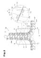
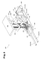
- Fig. 3 is a perspective view of the interlocking chain type forward and backward actuating device 200 including the interlocking chain units according to the invention.
- Fig. 4 is a perspective view of Fig. 3 from which a lifting table and a pantograph arm are removed.
- Fig. 5 is a partially enlarged view of a vicinity of a drive sprocket shown in Fig 4 .
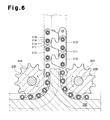
- Fig. 6 is a diagram showing a state of contact between a chain guide plate and the interlocking chains.
- the interlocking chain type forward and backward actuating device 200 having the above-described interlocking chain units 100 lifts and lowers a lifting table 210, on which a heavy object (not shown) is placed, in parallel with an installation floor face G as shown in Fig. 3 .
- the interlocking chain type forward and backward actuating device 200 includes the following as basic device structures: a base plate 220 mounted on the installation floor face G, with which the above-described lifting table 210 lifts and lowers in parallel; a pair of drive sprockets 240 facing each other and rotating in opposite directions, i.e., normal and reverse directions in the same plane and about a pair of rotating shafts 230 arranged parallel with the base plate 220; a pair of interlocking chain units 100, 100 each formed by paired pair of interlocking chains 110, 110 configured to lift and lower the lifting table 210 by becoming disengaged from the pair of drive sprockets 240, 240; the above-described lifting table 210 mounted to upper ends of the interlocking chain units 100, 100 and integrally lifting and lowering; power transmitting chains 252 for transmitting power to a speed changing gear set 253 for rotating the pair of drive sprockets 240, 240; a drive motor
- Chain housing means 270 are located in a region around the maximum lowering position of the lifting table 210, i.e., outside and away from a projected planform of the lifting table 210 similarly to the drive motor 250.
- one of the pair of interlocking chains 110, 110 disengaged from each other is housed into the chain housing means 270 formed by a chain housing box 271 of a chain reeling type arranged on a side of the drive motor 250 and the other of the pair of interlocking chains 110, 110 is housed into the chain housing means 270 formed by a straight housing rail 272 arranged on an opposite side facing the drive motor 250.
- the interlocking chain type forward and backward actuating device 200 is formed by providing a lifting and lowering assisting guide means 280, which is called an X-shaped pantograph arm and is formed by inner arms 281 and outer arms 282 by connecting upper and lower two stages, between the lifting table 210 and the base plate 220 on the installation floor face G to guide stable lifting and lowering movements of the lifting table 210.
- a lifting and lowering assisting guide means 280 which is called an X-shaped pantograph arm and is formed by inner arms 281 and outer arms 282 by connecting upper and lower two stages, between the lifting table 210 and the base plate 220 on the installation floor face G to guide stable lifting and lowering movements of the lifting table 210.
- Slide rails 283 slide lower ends of the inner arms 281 in response to the lifting and lowering movements.
- the pair of interlocking chains 110, 110 are respectively unreeled from the chain housing means 270 formed by the chain housing box 271 and the straight housing rail 272 by the pair of drive sprockets 240, 240 interlocked with the rollers 115, and the pair of interlocking chains 110, 110 are lifted at equal speeds and swiftly by the two power transmitting chains 252 looped over output gears 251 according to output of the drive motor 250 while supporting total weight of the lifting table 210 on which a lifted and lowered object (not shown), which is a heavy object, is placed.
- the above-described lifting and lowering assisting guide means 280 which is called the X-shaped pantograph arm and is formed by the inner arms 281 and the outer arms 282 by connecting the upper and lower two stages, guides the stable lifting movement of the lifting table 210.
- the pair of interlocking chains 110, 110 are disengaged from each other and respectively retracted into the chain housing means 270 formed by the chain housing box 271 and the straight housing rail 272 by the pair of drive sprockets 240, 240, and the pair of interlocking chains 110, 110 are lowered at equal speeds and swiftly by the two power transmitting chains 252 looped over the output gears 251 according to the output of the drive motor 250 while supporting the total weight of the lifting table 210, on which the heavy object (not shown) is placed.
- the above-described X-shaped lifting and lowering assisting guide means 280 formed by the inner arms 281 and the outer arms 282 by connecting the upper and lower two stages guides the stable lowering movement of the lifting table 210 while being folded.
- the drive sprockets 240 which are examples of the "chain movement restricting means" in the invention, move the lifting table 210, i.e., the driven body forward and backward according to the chain forward and backward movements based on the interlocking and disengagement of the pair of interlocking chains 110, 110.
- the rigidified chain portions 100A having the increased rigidity drives the lifting table 210 forward and backward. Therefore, the interlocking chain units 100 can accurately move the lifting table 210 forward and backward to the predetermined positions while avoiding buckling and twisting of the rigidified chain portions 110A.
- the hook-shaped interlocking end faces 111a, 111a of the two inner tooth plates 111, 111 interlocked with each other form the plate overlap regions P when the pair of interlocking chains 110, 110 are seen in the plate normal direction, i.e., the chain width direction W, orthogonal to the respective plate main faces 111P, 112P of the inner tooth plates 111 and the outer tooth plates 112.
- the plate overlap regions P are formed by the outlines of the two plate overlap portions Pa, Pa having the outer edges defined by the contact portion faces 111aa, 111aa, where the hook-shaped interlocking end faces 111a, 111a of the two inner tooth plates 111, 111 are in contact with each other and the flat buckling restricting end faces 112b, 112b of the two outer tooth plates 112, 112 in contact with each other.
- the general shapes of the outlines of the two plate overlap portions Pa, Pa are point-symmetric about the point C of intersection between the hook-shaped interlocking end faces 111a, 111a and the buckling restricting end faces 112b, 112b.
- the inner tooth plates 111, 111 are firmly and reliably interlocked with each other, the firm and reliable interlocking between the outer tooth plates 112, 112 due to the interlocking between the inner tooth plates 111, 111 is achieved, and the rigidity of the pair of interlocking chains 110, 110 interlocked and integrated with each other is increased to thereby avoid the buckling and the twisting of the rigidified chain portion 100A.
Landscapes
- Engineering & Computer Science (AREA)
- General Engineering & Computer Science (AREA)
- Mechanical Engineering (AREA)
- Life Sciences & Earth Sciences (AREA)
- Geology (AREA)
- Structural Engineering (AREA)
- Transmission Devices (AREA)
- Attitude Control For Articles On Conveyors (AREA)
Abstract
Description
- The present invention relates to an interlocking chain unit used in manufacturing facilities in various manufacturing fields, transportation facilities in the transportation field, nursing care facilities in medical and welfare fields, and stage facilities in art fields, and moving a driven body forward and backward.
- Conventionally, as a drive unit, a drive unit is known that moves a driven object such as a heavy object by using a pair of interlocking chains, which are also referred to as zip chains. Specifically, the pair of interlocking chains are interlocked with each other and integrally driven (for example, refer to Patent Document 1).
- Also, a silent chain transmission device has known in which noise and vibrations caused in driving of chains are suppressed by defining shapes of faces of link plates to be interlocked with inner flanks, i.e., sprocket teeth (for example, refer to Patent Document 2).
-
- Patent Document 1: Japanese Laid-Open Patent Publication No.
2009-113872 Fig. 5 ) - Patent Document 2: Japanese Laid-Open Utility Model Publication No.
6-13399 Fig. 1 ) - However, the above-described prior art related to the interlocking chains does not mention specific design matters such as interlocking end faces for engaging inner tooth plates and outer tooth plates with each other and buckling restricting end faces for restricting buckling. Therefore, it is difficult to firmly and reliably engage the inner tooth plates with the outer tooth plates.
- Moreover, in the above-described interlocking chains, uneven compression forces are applied to the inner tooth plates and the outer tooth plates when these plates are interlocked with each other and therefore it is difficult to avoid buckling caused in a rigidified chain portion of the pair of interlocking chains, which are interlocked and integrated with each other, and twisting of the rigidified chain portion.
- In other words, unavoidable clearance backlash between parts remains in the chains after the interlocking. Therefore, it is difficult to avoid the buckling caused in the rigidified chain portion and the twisting of the rigidified chain portion by suppressing application of the uneven compression forces in the interlocking.
- Therefore, a technical problem to be solved by the invention, i.e., an object of the invention is to provide an interlocking chain unit in which inner tooth plates and outer tooth plates are reliably and firmly interlocked with each other and rigidity of the pair of interlocking chains, which are interlocked and integrated with each other, is increased to thereby avoid buckling and twisting of the rigidified chain portion.
- To solve the above described problems, the invention according to claim 1 provides an interlocking chain unit comprising a pair of interlocking chains. Each interlocking chain is formed by connecting, with pairs of front and rear coupling pins, a large number of inner tooth plates and a large number of outer tooth plates in a chain longitudinal direction. The outer tooth plates are arranged to be adjacent to outer sides of the inner tooth plates and have partial overlap regions with the inner tooth plates. The interlocking chains are configured to become interlocked with each other to integrally become rigid in a rigid chain forward and backward movement direction and to become disengaged from each other to bifurcate. When the pair of interlocking chains are interlocked with each other, hook-shaped interlocking end faces of the two inner tooth plates interlocked with each other form plate overlap regions when the pair of interlocking chains are seen in a plate normal direction, which is orthogonal to plate main faces of the inner tooth plates and the outer tooth plates. Respective buckling restricting end faces of the two outer tooth plates come in contact with each other in a diagonal direction with respect to the rigid chain forward and backward movement direction. The plate overlap regions are formed by outlines of the two plate overlap portions having outer edges defined by contact portion faces, where the hook-shaped interlocking end faces of the two inner tooth plates are in contact with each other, and flat buckling restricting end faces of the two outer tooth plates in contact with each other. General shapes of the outlines of the two plate overlap portions are point-symmetric about a point of intersection between the hook-shaped interlocking end faces and the buckling restricting end faces. Any or all of the inner tooth plates, the outer tooth plates, and the coupling pins are elastically deformed to make the pair of interlocking chains rigid and to remove play between parts in forming the plate overlap regions.
- To solve the above described problems, the invention according to claim 1 provides the interlocking chain unit according to claim 1, in which the pair of interlocking chains are interlocked with each other by chain movement restricting means for restricting movements of the pair of interlocking chains in the rigid chain forward and backward movement direction.
- To solve the above described problems, the invention according to claim 3 provides the interlocking chain unit according to claim 2, in which the chain movement restricting means is a drive sprocket provided in an interlocking chain type forward and backward actuating device configured to move a driven body forward and backward according to chain forward and backward movements based on interlocking and disengagement of the pair of interlocking chains.
- The interlocking chain unit according to claim 1 of the present invention includes a pair of interlocking chains each formed by connecting, with pairs of front and rear coupling pins, a large number of inner tooth plates and a large number of outer tooth plates in a chain longitudinal direction. The outer tooth plates are arranged to be adjacent to the outer sides of the inner tooth plates and have partial overlap regions with the inner tooth plates. The interlocking chains are configured become interlocked with each other to integrally become rigid and to become disengaged from each other to bifurcate. Therefore, it is possible to switch between the rigid state of the chains and the bifurcating state of the chains according to the forward and backward movements of the pair of interlocking chains, and also to exert particular effects corresponding to the following unique structures.
- In the interlocking chain unit according to claim 1, when the pair of interlocking chains are interlocked with each other, the hook-shaped interlocking end faces of the two inner tooth plates interlocked with each other form the plate overlap regions when the pair of interlocking chains are seen in the plate normal direction orthogonal to the plate main faces of the inner tooth plates and the outer tooth plates. The plate overlap regions are formed by the outlines of the two plate overlap portions having the outer edges defined by the contact portion faces where the hook-shaped interlocking end faces of the two inner tooth plates are in contact with each other and the flat buckling restricting end faces of the two outer tooth plates in contact with each other. General shapes of the outlines of the two plate overlap portions are point-symmetric about the point of intersection between the hook-shaped interlocking end faces and the buckling restricting end faces. As a result, without unevenness of compression forces acting on the buckling restricting end faces on opposite sides of a center of the interlocking chain unit, displacement of the hook-shaped interlocking end faces interlocked with each other in a chain disengaged direction is avoided to thereby avoid disengagement of the pair of interlocking chains. The buckling restricting end faces in contact with each other balance the compression forces acting on the buckling restricting end faces in the same plane, i.e., a plane including the outer tooth plates. In this way, the inner tooth plates are firmly and reliably interlocked with each other, the firm and reliable interlocking between the outer tooth plates due to the interlocking between the inner tooth plates is achieved, and the rigidity of the pair of interlocking chains interlocked and integrated with each other is increased to thereby avoid the buckling and the twisting of the rigidified chain portion.
- The respective buckling restricting end faces of the two outer tooth plates come in contact with each other in a diagonal direction with respect to the rigid chain forward and backward movement direction to thereby allow the compression forces acting on the buckling restricting end faces in the rigid chain forward and backward movement direction to escape in the above-described diagonal direction and also the hook-shaped interlocking end faces restrict disengagement of the pair of interlocking chains. Therefore, while avoiding loading of stress on the buckling restricting end faces, the inner tooth plates and the outer tooth plates are firmly and reliably interlocked with each other and the rigidity of the pair of interlocking chains interlocked and integrated with each other is increased to thereby reliably avoid the buckling and the twisting of the rigidified chain portion.
- Any or all of the inner tooth plates, the outer tooth plates, and the coupling pins are elastically deformed to make the pair of interlocking chains rigid and to remove play between parts in forming the plate overlap regions. Therefore, while the interlocking chains are made rigid and the play between the parts is removed by the elastic deformation, backlash is further reduced. As a result, the inner tooth plates and the outer tooth plates are firmly and reliably interlocked with each other and the rigidity of the pair of interlocking chains interlocked and integrated with each other is increased to thereby further avoid the buckling and the twisting of the rigidified chain portion.
- In the interlocking chain unit according to claim 2, in addition to the effects exerted by the interlocking chain unit according to claim 1, the pair of interlocking chains are interlocked with each other by the chain movement restricting means for restricting the movements of the pair of interlocking chains in the rigid chain forward and backward movement direction. Since the interlocking chains are interlocked with each other while the outer tooth plates and the inner tooth plates are guided in the rigid chain forward and backward movement direction, it is possible to achieve reliable interlocking between the pair of interlocking chains.
- In the interlocking chain unit according to claim 3, in addition to the effects exerted by the interlocking chain unit according to claim 2, the chain movement restricting means is a drive sprocket provided in an interlocking chain type forward and backward actuating device configured to move a driven body forward and backward according to the chain forward and backward movements based on the interlocking and the disengagement of the pair of interlocking chains. Since the driven body is driven to move forward and backward by the rigidified chain portion having the increased rigidity, it is possible to achieve accurate forward and backward movements of the driven body to predetermined positions while avoiding buckling and twisting of the rigidified chain portion.
-
- Fig. 1
- is a perspective view of an exploded state of an interlocking chain unit according to one embodiment of the present invention;
- Fig. 2
- is a front view of an interlocked portion where a pair of interlocking chains are interlocked with each other;
- Fig. 3
- is a perspective view of an interlocking chain type forward and backward actuating device including the interlocking chain units according to the invention;
- Fig. 4
- is a perspective view of
Fig. 3 from which a lifting table and a pantograph arm are removed; - Fig. 5
- is a partially enlarged view of a vicinity of a drive sprocket shown in
Fig 4 ; and - Fig. 6
- is a diagram showing a state of contact between a chain guide plate and the interlocking chains.
- An interlocking chain unit according to the present invention includes a pair of interlocking chains each formed by connecting, with pairs of front and rear coupling pins, a large number of inner tooth plates and a large number of outer tooth plates, which are arranged to be adjacent to outer sides of the inner tooth plates and have partial overlap regions with the inner tooth plates, in a chain longitudinal direction. The interlocking chains become interlocked with each other to integrally become rigid in a rigid chain forward and backward movement direction and become disengaged from each other to bifurcate. When the pair of interlocking chains become interlocked with each other, hook-shaped interlocking end faces of the two inner tooth plates interlocked with each other form plate overlap regions when the pair of interlocking chains are seen in a plate normal direction orthogonal to plate main faces of the inner tooth plates and the outer tooth plates, and buckling restricting end faces of the two outer tooth plates come in contact with each other in a diagonal direction with respect to the rigid chain forward and backward movement direction. The plate overlap regions are formed by outlines of the two plate overlap portions having outer edges defined by contact portion faces where the hook-shaped interlocking end faces of the two inner tooth plates are in contact with each other and flat buckling restricting end faces of the two outer tooth plates in contact with each other. General shapes of the outlines of the two plate overlap portions are point-symmetric about the point of intersection between the hook-shaped interlocking end faces and the buckling restricting end faces. Any or all of the inner tooth plates, the outer tooth plates, and the coupling pins are elastically deformed to make the pair of interlocking chains rigid and to remove play between parts in forming the plate overlap regions. If the interlocking chain unit according to the invention has the above-described structure, the invention may be carried out in any specific modes.
- The interlocking chain unit may be constituted by a plurality of rows of chain units in which a large number of link units are respectively coupled in the chain longitudinal direction. The link unit includes inner tooth plates and outer tooth plates located outside of the inner tooth plates. An inner tooth plate and an outer tooth plate constitute one set of the link unit facing in the chain width direction. The interlocking chain unit may also be constituted by a chain unit of a single row.
- The effects exerted by the above-described buckling restricting end faces of the outer tooth plates and the hook-shaped interlocking end faces of the inner plates are exerted similarly when the outer plates and the inner plates are replaced with each other, i.e., the buckling restricting end faces of the inner tooth plates and the hook-shaped interlocking end faces of the outer tooth plates are replaced with each other.
- Effects similar to the above-described effects are exerted if recessed notches are formed at parts of the hook-shaped interlocking end faces or the buckling restricting end faces of one of the pair of interlocking chains.
- The interlocking chain type forward and backward actuating device including the interlocking chain units according to the invention does not cause any problem in forward and backward operations even if an installation face is a floor face where the interlocking chain type forward and backward actuating device stands or a ceiling face where the interlocking chain type forward and backward actuating device is suspended. Further, even if the installation face is a vertical wall face where the interlocking chain type forward and backward actuating device is cantilevered, the device has no trouble in the above-described forward and backward movements.
- An interlocking
chain unit 100 according to one embodiment of the invention will be described below based onFigs. 1 and2 . -
Fig. 1 is a perspective view of an exploded state of the interlocking chain unit according to the embodiment of the invention, andFig. 2 is a front view of an interlocked portion where a pair of interlocking chains are interlocked with each other. - As shown in
Figs. 1 and2 , the interlockingchain unit 100 according to the embodiment is what is called a zip chain and includes a pair of interlockingchains inner tooth plates 111 and a large number ofouter tooth plates 112, which are arranged to be adjacent to outer sides of theinner tooth plates 111 and have partial overlap regions with theinner tooth plates 111, in a chain longitudinal direction. The interlockingchains -
Rollers 115 are fitted overbushings 114, which are fitted in theinner tooth plates 111, into which the coupling pins 113 are loosely fitted, and which are respectively arranged between a pair ofinner tooth plates - Next, a concrete form of the most characteristic structure of the above-described
interlocking chain unit 100 of the embodiment will be described in more detail based onFigs. 1 and2 . - The interlocking
chain unit 100 is formed such that, when the pair of interlockingchains inner tooth plates chains inner tooth plates 111 and theouter tooth plates 112. The plate overlap regions P are formed by the outlines of the two plate overlap portions Pa, Pa having the outer edges defined by the contact portion faces 111aa, 111aa, where the hook-shaped interlocking end faces 111a, 111a of the twoinner tooth plates outer tooth plates chain unit 100, displacement of the hook-shaped interlocking end faces 111a, 111a interlocked with each other in a chain disengaged direction B is avoided to avoid disengagement of the pair of interlockingchains outer tooth plates 112. In this way, theinner tooth plates outer tooth plates inner tooth plates chains rigidified chain portion 100A. - The entire general shapes of the outlines of the two plate overlap portions Pa, Pa are not necessarily point-symmetric about the point C of intersection between the hook-shaped interlocking end faces 111a, 111a and the buckling restricting end faces 112b, 112b. If at least parts of the general shapes of the outlines of the two plate overlap portions Pa, Pa are point-symmetric about the point C of intersection, the above-described effects of avoiding the buckling and the twisting are sufficiently obtained.
- In the interlocking
chain unit 100, the buckling restricting end faces 112b, 112b of the twoouter tooth plates chains inner tooth plates outer tooth plates chains rigidified chain portion 100A. - In the interlocking
chain unit 100, any or all of theinner tooth plates 111, theouter tooth plates 112, and the coupling pins 113 are elastically deformed to make the pair of interlocking chains rigid and to remove play between parts in forming the plate overlap regions P. Therefore, while the interlockingchains inner tooth plates outer tooth plates chains rigidified chain portion 100A. - Moreover, in the interlocking
chain unit 100, the pair of interlockingchains chains outer tooth plates 112 and theinner tooth plates 111 are guided into the rigid chain forward and backward movement direction A, the interlockingchains chains - The chain movement restricting means M, M may be any means, if they retain the interlocking
chain unit 100 from opposite sides and guide the interlockingchain unit 100 into the rigid chain forward and backward movement direction A in a region between the chain movement restricting means M, M. - Next, based on
Figs. 1 to 6 , an interlocking chain type forward andbackward actuating device 200 having the above-describedinterlocking chain units 100 will be described. -
Fig. 3 is a perspective view of the interlocking chain type forward andbackward actuating device 200 including the interlocking chain units according to the invention.Fig. 4 is a perspective view ofFig. 3 from which a lifting table and a pantograph arm are removed.Fig. 5 is a partially enlarged view of a vicinity of a drive sprocket shown inFig 4 .Fig. 6 is a diagram showing a state of contact between a chain guide plate and the interlocking chains. - The interlocking chain type forward and
backward actuating device 200 having the above-describedinterlocking chain units 100 lifts and lowers a lifting table 210, on which a heavy object (not shown) is placed, in parallel with an installation floor face G as shown inFig. 3 . - As shown in
Figs. 3 to 6 , the interlocking chain type forward andbackward actuating device 200 includes the following as basic device structures: abase plate 220 mounted on the installation floor face G, with which the above-described lifting table 210 lifts and lowers in parallel; a pair ofdrive sprockets 240 facing each other and rotating in opposite directions, i.e., normal and reverse directions in the same plane and about a pair ofrotating shafts 230 arranged parallel with thebase plate 220; a pair of interlockingchain units chains drive sprockets chain units power transmitting chains 252 for transmitting power to a speed changing gear set 253 for rotating the pair ofdrive sprockets drive motor 250 for driving thepower transmitting chains 252; andchain guide plates 260 provided in bifurcation regions between the pair ofdrive sprockets 240 to guide and move the interlockingchain units 100. - Chain housing means 270 are located in a region around the maximum lowering position of the lifting table 210, i.e., outside and away from a projected planform of the lifting table 210 similarly to the
drive motor 250. - In other words, one of the pair of interlocking
chains chain housing box 271 of a chain reeling type arranged on a side of thedrive motor 250 and the other of the pair of interlockingchains straight housing rail 272 arranged on an opposite side facing thedrive motor 250. - The interlocking chain type forward and
backward actuating device 200 is formed by providing a lifting and lowering assisting guide means 280, which is called an X-shaped pantograph arm and is formed byinner arms 281 andouter arms 282 by connecting upper and lower two stages, between the lifting table 210 and thebase plate 220 on the installation floor face G to guide stable lifting and lowering movements of the lifting table 210. - Slide rails 283 slide lower ends of the
inner arms 281 in response to the lifting and lowering movements. - Next, the lifting and lowering movements of the interlocking chain type forward and
backward actuating device 200 including the interlockingchain units 100 according to the embodiment will be described based onFigs. 3 and6 . - As shown in
Figs. 3 and6 , when the lifting table 210 reaches a maximum lifting position, the pair of interlockingchains chain housing box 271 and thestraight housing rail 272 by the pair ofdrive sprockets rollers 115, and the pair of interlockingchains power transmitting chains 252 looped over output gears 251 according to output of thedrive motor 250 while supporting total weight of the lifting table 210 on which a lifted and lowered object (not shown), which is a heavy object, is placed. - At this time, the above-described lifting and lowering assisting guide means 280, which is called the X-shaped pantograph arm and is formed by the
inner arms 281 and theouter arms 282 by connecting the upper and lower two stages, guides the stable lifting movement of the lifting table 210. - On the other hand, when the lifting table 210 reaches the maximum lowering position, the pair of interlocking
chains chain housing box 271 and thestraight housing rail 272 by the pair ofdrive sprockets chains power transmitting chains 252 looped over the output gears 251 according to the output of thedrive motor 250 while supporting the total weight of the lifting table 210, on which the heavy object (not shown) is placed. - At this time, the above-described X-shaped lifting and lowering assisting guide means 280 formed by the
inner arms 281 and theouter arms 282 by connecting the upper and lower two stages guides the stable lowering movement of the lifting table 210 while being folded. - Particularly, in the interlocking chain type forward and
backward actuating device 200, thedrive sprockets 240, which are examples of the "chain movement restricting means" in the invention, move the lifting table 210, i.e., the driven body forward and backward according to the chain forward and backward movements based on the interlocking and disengagement of the pair of interlockingchains rigidified chain portions 100A having the increased rigidity drives the lifting table 210 forward and backward. Therefore, the interlockingchain units 100 can accurately move the lifting table 210 forward and backward to the predetermined positions while avoiding buckling and twisting of the rigidified chain portions 110A. - In the interlocking
chain unit 100 according to the embodiment and obtained as described above, when the pair of interlockingchains inner tooth plates chains inner tooth plates 111 and theouter tooth plates 112. The plate overlap regions P are formed by the outlines of the two plate overlap portions Pa, Pa having the outer edges defined by the contact portion faces 111aa, 111aa, where the hook-shaped interlocking end faces 111a, 111a of the twoinner tooth plates outer tooth plates inner tooth plates outer tooth plates inner tooth plates chains rigidified chain portion 100A. -
- 100
- interlocking chain unit
- 100A
- rigidified chain portion
- 110
- interlocking chain
- 111
- inner tooth plate
- 111a
- hook-shaped interlocking end face of inner tooth plate
- 111aa
- contact portion face of inner tooth plate
- 112b
- buckling restricting end face of outer tooth plate
- 111P, 112P
- plate main face
- 112
- outer tooth plate
- 113
- coupling pin
- 114
- bushing
- 115
- roller
- 200
- interlocking chain type forward and backward actuating device
- 210
- lifting table
- 220
- base plate
- 230
- rotating shaft of drive sprocket
- 240
- driving sprocket
- 250
- drive motor
- 251
- output gear
- 252
- power transmitting chain
- 253
- group of speed change gears
- 260
- chain guide plate
- 270
- chain housing means
- 271
- chain housing box
- 272
- straight housing rail
- 280
- lifting and lowering assisting guide means
- 281
- inner arm
- 282
- outer arm
- A
- rigid chain forward and backward movement direction
- B
- chain disengaged direction
- C
- point of intersection
- G
- installation face
- M
- chain movement restricting means
- P
- plate overlap region
- Pa
- plate overlap portion
- T
- diagonal direction
- W
- chain width direction
Claims (3)
- An interlocking chain unit comprising a pair of interlocking chains, wherein
each interlocking chain is formed by connecting, with pairs of front and rear coupling pins, a large number of inner tooth plates and a large number of outer tooth plates in a chain longitudinal direction,
the outer tooth plates are arranged to be adjacent to outer sides of the inner tooth plates and have partial overlap regions with the inner tooth plates, and
the interlocking chains are configured to become interlocked with each other to integrally become rigid in a rigid chain forward and backward movement direction and to become disengaged from each other to bifurcate,
the interlocking chain unit being characterized in that when the pair of interlocking chains are interlocked with each other, hook-shaped interlocking end faces of the two inner tooth plates interlocked with each other form plate overlap regions when the pair of interlocking chains are seen in a plate normal direction, which is orthogonal to plate main faces of the inner tooth plates and the outer tooth plates,
respective buckling restricting end faces of the two outer tooth plates come in contact with each other in a diagonal direction with respect to the rigid chain forward and backward movement direction,
the plate overlap regions are formed by outlines of the two plate overlap portions having outer edges defined by contact portion faces, where the hook-shaped interlocking end faces of the two inner tooth plates are in contact with each other, and flat buckling restricting end faces of the two outer tooth plates in contact with each other, general shapes of the outlines of the two plate overlap portions are point-symmetric about a point of intersection between the hook-shaped interlocking end faces and the buckling restricting end faces, and
any or all of the inner tooth plates, the outer tooth plates, and the coupling pins are elastically deformed to make the pair of interlocking chains rigid and to remove play between parts in forming the plate overlap regions. - The interlocking chain unit according to claim 1, characterized in that the pair of interlocking chains are interlocked with each other by chain movement restricting means for restricting movements of the pair of interlocking chains in the rigid chain forward and backward movement direction.
- The interlocking chain unit according to claim 2, characterized in that the chain movement restricting means is a drive sprocket provided in an interlocking chain type forward and backward actuating device configured to move a driven body forward and backward according to chain forward and backward movements based on interlocking and disengagement of the pair of interlocking chains.
Applications Claiming Priority (2)
| Application Number | Priority Date | Filing Date | Title |
|---|---|---|---|
| JP2011094434A JP4865923B1 (en) | 2011-04-20 | 2011-04-20 | Meshing chain unit |
| PCT/JP2012/056703 WO2012144281A1 (en) | 2011-04-20 | 2012-03-15 | Engagement chain unit |
Publications (3)
| Publication Number | Publication Date |
|---|---|
| EP2700844A1 true EP2700844A1 (en) | 2014-02-26 |
| EP2700844A4 EP2700844A4 (en) | 2015-10-07 |
| EP2700844B1 EP2700844B1 (en) | 2019-09-11 |
Family
ID=45781857
Family Applications (1)
| Application Number | Title | Priority Date | Filing Date |
|---|---|---|---|
| EP12774681.6A Active EP2700844B1 (en) | 2011-04-20 | 2012-03-15 | Engagement chain unit |
Country Status (7)
| Country | Link |
|---|---|
| US (1) | US9482313B2 (en) |
| EP (1) | EP2700844B1 (en) |
| JP (1) | JP4865923B1 (en) |
| KR (1) | KR101532503B1 (en) |
| CN (1) | CN103492756B (en) |
| ES (1) | ES2759580T3 (en) |
| WO (1) | WO2012144281A1 (en) |
Cited By (3)
| Publication number | Priority date | Publication date | Assignee | Title |
|---|---|---|---|---|
| DE102016006302A1 (en) * | 2016-05-27 | 2017-11-30 | B. Ketterer Söhne GmbH & Co. KG | Height adjustment device for a piece of furniture |
| FR3061753A1 (en) * | 2017-01-10 | 2018-07-13 | Serapid - France | THRUST CHAIN DEVICE |
| US10830535B2 (en) | 2016-03-18 | 2020-11-10 | I.M.A. Industria Macchine Automatiche S.P.A. | Apparatus for loading and unloading a freeze-dryer |
Families Citing this family (14)
| Publication number | Priority date | Publication date | Assignee | Title |
|---|---|---|---|---|
| DE102012113082A1 (en) * | 2012-12-24 | 2014-06-26 | Tsubaki Kabelschlepp GmbH | Energy guiding device with at least one drive device for long travel distances |
| CN104514855A (en) * | 2013-09-29 | 2015-04-15 | 张铭勇 | Chain pole and chain pole device |
| JP6468583B2 (en) * | 2014-08-01 | 2019-02-13 | 株式会社不動テトラ | Underground work device and underground work method using the same |
| KR101633850B1 (en) | 2015-01-22 | 2016-06-27 | 임오배 | Lifting Apparatus Of Toothed Gear Chain |
| FR3095024B1 (en) * | 2019-04-10 | 2021-08-06 | Serapid France | RIGID FLEXIBLE MULTILINEAR ACTUATOR |
| CN110406418B (en) * | 2019-09-24 | 2020-01-10 | 国创新能源汽车能源与信息创新中心(江苏)有限公司 | Movement mechanism with flexibly variable rigidity |
| CN110816752B (en) * | 2019-10-14 | 2024-05-28 | 南京市同亮科技有限公司 | Traction mechanism for marine rescue ship |
| KR102840047B1 (en) * | 2019-10-25 | 2025-07-28 | 엘지디스플레이 주식회사 | Display device |
| CN113103890B (en) * | 2021-05-17 | 2022-10-25 | 青岛特来电新能源科技有限公司 | Telescopic arm, charging manipulator and charging device |
| US11787069B2 (en) * | 2021-11-01 | 2023-10-17 | Oliver Crispin Robotics Limited | Insertion tool with flexible spine |
| KR102888575B1 (en) * | 2021-12-27 | 2025-11-19 | 엘지디스플레이 주식회사 | Display device |
| CN118323715A (en) * | 2023-01-12 | 2024-07-12 | 深圳市海柔创新科技有限公司 | Pick and place components, forks, robots and storage systems |
| EP4497967A1 (en) * | 2023-07-28 | 2025-01-29 | ABB E-mobility B.V. | Belt and actuator belt system |
| WO2025129312A1 (en) * | 2023-12-18 | 2025-06-26 | Jansen Van Rensburg Hendrik | Hollow segmented linear actuator |
Family Cites Families (36)
| Publication number | Priority date | Publication date | Assignee | Title |
|---|---|---|---|---|
| US2574657A (en) * | 1945-10-23 | 1951-11-13 | Harold C Pierce | Flexible power transmitting mechanism |
| US3645146A (en) * | 1969-09-29 | 1972-02-29 | Tony Nagin | Interlocking chain structure |
| FR2258342B1 (en) | 1974-01-17 | 1978-04-21 | Sietam | |
| JPS51131060A (en) * | 1975-05-06 | 1976-11-15 | Tsubakimoto Chain Co | Interlocking chain device |
| JPS6458883A (en) | 1987-08-27 | 1989-03-06 | Toto Ltd | Combination faucet |
| JPH0613399Y2 (en) | 1988-02-08 | 1994-04-06 | ボーグ・ワーナー・オートモーティブ株式会社 | Silent chain transmission |
| JPH0312646A (en) | 1989-06-12 | 1991-01-21 | Asahi Chem Ind Co Ltd | Novel dyestuff recording material |
| JPH053300A (en) | 1990-10-05 | 1993-01-08 | Nippon Steel Corp | Semiconductor device |
| FR2667926B1 (en) | 1990-10-11 | 1993-02-19 | Burri Alain Sa | TRANSFORMABLE STRUCTURE ELEMENT. |
| US5355643A (en) | 1991-10-04 | 1994-10-18 | Alain Burri Sa | Transformable structural element |
| JPH0746079Y2 (en) | 1993-04-22 | 1995-10-18 | 株式会社明電舎 | Inverter automatic switching device |
| WO1996019405A1 (en) | 1994-12-19 | 1996-06-27 | Sanin Boruto Seisakujo Co., Ltd. | Rod-shaped extension body |
| JPH09119495A (en) * | 1995-10-24 | 1997-05-06 | Sanin Booruto Seisakusho:Kk | Stretch feeding device for band body |
| US5690571A (en) | 1996-09-11 | 1997-11-25 | Borg-Warner Automotive, Inc. | Hybrid roller and silent chain |
| US5895880A (en) | 1997-10-14 | 1999-04-20 | Western Design Howden | Zipper chain projectile rammer |
| JP3370928B2 (en) | 1998-03-30 | 2003-01-27 | 株式会社椿本チエイン | Lifting device using meshing chain |
| WO2005108821A1 (en) | 2004-05-12 | 2005-11-17 | Vkr Holding A/S | Push-pull chain and actuator |
| CN2837608Y (en) | 2004-05-12 | 2006-11-15 | Vkr控股公司 | Push-pull chain and actuator |
| US7621078B2 (en) | 2005-01-20 | 2009-11-24 | Drs Sustainment Systems, Inc. | Telescoping mast having variable height locking and a chain erection mechanism with a cable management system |
| JP4657131B2 (en) | 2006-03-30 | 2011-03-23 | トヨタ自動車株式会社 | Stock conveyor |
| JP2008256202A (en) | 2007-03-13 | 2008-10-23 | Moritoshi Kondou | Expansion device |
| JP4723538B2 (en) * | 2007-06-21 | 2011-07-13 | 株式会社椿本チエイン | Engagement chain type lifting device |
| JP4970162B2 (en) | 2007-06-22 | 2012-07-04 | 株式会社椿本チエイン | Engagement chain type lifting device |
| JP2009113872A (en) | 2007-11-01 | 2009-05-28 | Tsubakimoto Chain Co | Meshing chain for driving lifting and lowering |
| JP4509165B2 (en) * | 2007-11-01 | 2010-07-21 | 株式会社椿本チエイン | Engagement multi-row chain for lifting drive |
| JP2009242010A (en) | 2008-03-28 | 2009-10-22 | Tsubakimoto Chain Co | Meshing chain type lifting device |
| JP4641548B2 (en) | 2008-04-11 | 2011-03-02 | 株式会社椿本チエイン | Engagement chain type lifting device |
| JP5340670B2 (en) | 2008-08-22 | 2013-11-13 | 株式会社椿本チエイン | Engagement multi-row chain for lifting drive |
| JP4662499B2 (en) * | 2008-08-29 | 2011-03-30 | 株式会社椿本チエイン | Meshing chain |
| JP4662500B2 (en) * | 2008-09-09 | 2011-03-30 | 株式会社椿本チエイン | Engagement chain drive |
| JP4662503B2 (en) | 2008-12-09 | 2011-03-30 | 株式会社椿本チエイン | Meshing chain |
| JP4860772B1 (en) | 2011-01-05 | 2012-01-25 | 株式会社椿本チエイン | Stopper for meshing chain |
| JP5079892B2 (en) | 2011-01-12 | 2012-11-21 | 株式会社椿本チエイン | Engagement chain type advance / retreat actuator |
| JP4897093B1 (en) | 2011-01-27 | 2012-03-14 | 株式会社椿本チエイン | Engagement chain type advance / retreat actuator |
| JP4897094B1 (en) | 2011-02-10 | 2012-03-14 | 株式会社椿本チエイン | Engagement chain type advance / retreat actuator |
| JP4875216B1 (en) | 2011-05-12 | 2012-02-15 | 株式会社椿本チエイン | Meshing chain unit |
-
2011
- 2011-04-20 JP JP2011094434A patent/JP4865923B1/en active Active
-
2012
- 2012-03-15 ES ES12774681T patent/ES2759580T3/en active Active
- 2012-03-15 EP EP12774681.6A patent/EP2700844B1/en active Active
- 2012-03-15 WO PCT/JP2012/056703 patent/WO2012144281A1/en not_active Ceased
- 2012-03-15 KR KR1020137029427A patent/KR101532503B1/en active Active
- 2012-03-15 US US14/112,077 patent/US9482313B2/en active Active
- 2012-03-15 CN CN201280018797.7A patent/CN103492756B/en active Active
Cited By (5)
| Publication number | Priority date | Publication date | Assignee | Title |
|---|---|---|---|---|
| US10830535B2 (en) | 2016-03-18 | 2020-11-10 | I.M.A. Industria Macchine Automatiche S.P.A. | Apparatus for loading and unloading a freeze-dryer |
| DE102016006302A1 (en) * | 2016-05-27 | 2017-11-30 | B. Ketterer Söhne GmbH & Co. KG | Height adjustment device for a piece of furniture |
| FR3061753A1 (en) * | 2017-01-10 | 2018-07-13 | Serapid - France | THRUST CHAIN DEVICE |
| WO2018130769A1 (en) * | 2017-01-10 | 2018-07-19 | Serapid - France | Thrust chain device |
| US11358842B2 (en) | 2017-01-10 | 2022-06-14 | Serapid—France | Thrust chain device |
Also Published As
| Publication number | Publication date |
|---|---|
| JP2012225439A (en) | 2012-11-15 |
| KR20130140171A (en) | 2013-12-23 |
| ES2759580T3 (en) | 2020-05-11 |
| CN103492756B (en) | 2016-01-20 |
| US20140041467A1 (en) | 2014-02-13 |
| EP2700844A4 (en) | 2015-10-07 |
| KR101532503B1 (en) | 2015-06-29 |
| US9482313B2 (en) | 2016-11-01 |
| WO2012144281A1 (en) | 2012-10-26 |
| EP2700844B1 (en) | 2019-09-11 |
| JP4865923B1 (en) | 2012-02-01 |
| CN103492756A (en) | 2014-01-01 |
Similar Documents
| Publication | Publication Date | Title |
|---|---|---|
| EP2700844B1 (en) | Engagement chain unit | |
| EP2708775B1 (en) | Engagement chain unit | |
| JP4662499B2 (en) | Meshing chain | |
| JP4662503B2 (en) | Meshing chain | |
| JP4723538B2 (en) | Engagement chain type lifting device | |
| KR101116367B1 (en) | Engagement chain type driving device | |
| US8500101B2 (en) | Engagement chain | |
| JP4662504B2 (en) | Engagement chain for lifting drive | |
| JP4509165B2 (en) | Engagement multi-row chain for lifting drive | |
| KR20100023735A (en) | Hoisting and lowering driving engagement multi-row chain | |
| JP2009113872A (en) | Meshing chain for driving lifting and lowering | |
| JP2011105505A (en) | Meshing chain type forward and backward actuating device | |
| JP2011126630A (en) | Meshing chain type lifting device | |
| JP4658109B2 (en) | Engagement chain type lifting device | |
| JP5046899B2 (en) | Engagement chain for lifting drive | |
| JP2009263047A (en) | Engagement chain type lifter | |
| WO2012046491A1 (en) | Engagement chain | |
| JP2011153030A (en) | Engaging chain type advancing and retreating actuator |
Legal Events
| Date | Code | Title | Description |
|---|---|---|---|
| PUAI | Public reference made under article 153(3) epc to a published international application that has entered the european phase |
Free format text: ORIGINAL CODE: 0009012 |
|
| 17P | Request for examination filed |
Effective date: 20131105 |
|
| AK | Designated contracting states |
Kind code of ref document: A1 Designated state(s): AL AT BE BG CH CY CZ DE DK EE ES FI FR GB GR HR HU IE IS IT LI LT LU LV MC MK MT NL NO PL PT RO RS SE SI SK SM TR |
|
| DAX | Request for extension of the european patent (deleted) | ||
| RA4 | Supplementary search report drawn up and despatched (corrected) |
Effective date: 20150909 |
|
| RIC1 | Information provided on ipc code assigned before grant |
Ipc: B66F 3/06 20060101ALI20150903BHEP Ipc: F16G 13/20 20060101ALI20150903BHEP Ipc: F16H 19/06 20060101AFI20150903BHEP |
|
| REG | Reference to a national code |
Ref country code: DE Ref legal event code: R079 Ref document number: 602012063907 Country of ref document: DE Free format text: PREVIOUS MAIN CLASS: F16H0019020000 Ipc: F16H0019060000 |
|
| RIC1 | Information provided on ipc code assigned before grant |
Ipc: F16G 13/04 20060101ALI20190214BHEP Ipc: F16H 19/06 20060101AFI20190214BHEP Ipc: F16G 13/20 20060101ALI20190214BHEP Ipc: B66F 3/06 20060101ALI20190214BHEP |
|
| GRAP | Despatch of communication of intention to grant a patent |
Free format text: ORIGINAL CODE: EPIDOSNIGR1 |
|
| STAA | Information on the status of an ep patent application or granted ep patent |
Free format text: STATUS: GRANT OF PATENT IS INTENDED |
|
| INTG | Intention to grant announced |
Effective date: 20190402 |
|
| GRAS | Grant fee paid |
Free format text: ORIGINAL CODE: EPIDOSNIGR3 |
|
| GRAA | (expected) grant |
Free format text: ORIGINAL CODE: 0009210 |
|
| STAA | Information on the status of an ep patent application or granted ep patent |
Free format text: STATUS: THE PATENT HAS BEEN GRANTED |
|
| AK | Designated contracting states |
Kind code of ref document: B1 Designated state(s): AL AT BE BG CH CY CZ DE DK EE ES FI FR GB GR HR HU IE IS IT LI LT LU LV MC MK MT NL NO PL PT RO RS SE SI SK SM TR |
|
| REG | Reference to a national code |
Ref country code: GB Ref legal event code: FG4D |
|
| REG | Reference to a national code |
Ref country code: CH Ref legal event code: EP |
|
| REG | Reference to a national code |
Ref country code: AT Ref legal event code: REF Ref document number: 1178845 Country of ref document: AT Kind code of ref document: T Effective date: 20190915 |
|
| REG | Reference to a national code |
Ref country code: DE Ref legal event code: R096 Ref document number: 602012063907 Country of ref document: DE Ref country code: IE Ref legal event code: FG4D |
|
| REG | Reference to a national code |
Ref country code: NL Ref legal event code: MP Effective date: 20190911 |
|
| REG | Reference to a national code |
Ref country code: LT Ref legal event code: MG4D |
|
| PG25 | Lapsed in a contracting state [announced via postgrant information from national office to epo] |
Ref country code: SE Free format text: LAPSE BECAUSE OF FAILURE TO SUBMIT A TRANSLATION OF THE DESCRIPTION OR TO PAY THE FEE WITHIN THE PRESCRIBED TIME-LIMIT Effective date: 20190911 Ref country code: BG Free format text: LAPSE BECAUSE OF FAILURE TO SUBMIT A TRANSLATION OF THE DESCRIPTION OR TO PAY THE FEE WITHIN THE PRESCRIBED TIME-LIMIT Effective date: 20191211 Ref country code: NO Free format text: LAPSE BECAUSE OF FAILURE TO SUBMIT A TRANSLATION OF THE DESCRIPTION OR TO PAY THE FEE WITHIN THE PRESCRIBED TIME-LIMIT Effective date: 20191211 Ref country code: HR Free format text: LAPSE BECAUSE OF FAILURE TO SUBMIT A TRANSLATION OF THE DESCRIPTION OR TO PAY THE FEE WITHIN THE PRESCRIBED TIME-LIMIT Effective date: 20190911 Ref country code: FI Free format text: LAPSE BECAUSE OF FAILURE TO SUBMIT A TRANSLATION OF THE DESCRIPTION OR TO PAY THE FEE WITHIN THE PRESCRIBED TIME-LIMIT Effective date: 20190911 Ref country code: LT Free format text: LAPSE BECAUSE OF FAILURE TO SUBMIT A TRANSLATION OF THE DESCRIPTION OR TO PAY THE FEE WITHIN THE PRESCRIBED TIME-LIMIT Effective date: 20190911 |
|
| PG25 | Lapsed in a contracting state [announced via postgrant information from national office to epo] |
Ref country code: GR Free format text: LAPSE BECAUSE OF FAILURE TO SUBMIT A TRANSLATION OF THE DESCRIPTION OR TO PAY THE FEE WITHIN THE PRESCRIBED TIME-LIMIT Effective date: 20191212 Ref country code: LV Free format text: LAPSE BECAUSE OF FAILURE TO SUBMIT A TRANSLATION OF THE DESCRIPTION OR TO PAY THE FEE WITHIN THE PRESCRIBED TIME-LIMIT Effective date: 20190911 Ref country code: RS Free format text: LAPSE BECAUSE OF FAILURE TO SUBMIT A TRANSLATION OF THE DESCRIPTION OR TO PAY THE FEE WITHIN THE PRESCRIBED TIME-LIMIT Effective date: 20190911 Ref country code: AL Free format text: LAPSE BECAUSE OF FAILURE TO SUBMIT A TRANSLATION OF THE DESCRIPTION OR TO PAY THE FEE WITHIN THE PRESCRIBED TIME-LIMIT Effective date: 20190911 |
|
| REG | Reference to a national code |
Ref country code: AT Ref legal event code: MK05 Ref document number: 1178845 Country of ref document: AT Kind code of ref document: T Effective date: 20190911 |
|
| PG25 | Lapsed in a contracting state [announced via postgrant information from national office to epo] |
Ref country code: NL Free format text: LAPSE BECAUSE OF FAILURE TO SUBMIT A TRANSLATION OF THE DESCRIPTION OR TO PAY THE FEE WITHIN THE PRESCRIBED TIME-LIMIT Effective date: 20190911 Ref country code: PL Free format text: LAPSE BECAUSE OF FAILURE TO SUBMIT A TRANSLATION OF THE DESCRIPTION OR TO PAY THE FEE WITHIN THE PRESCRIBED TIME-LIMIT Effective date: 20190911 Ref country code: PT Free format text: LAPSE BECAUSE OF FAILURE TO SUBMIT A TRANSLATION OF THE DESCRIPTION OR TO PAY THE FEE WITHIN THE PRESCRIBED TIME-LIMIT Effective date: 20200113 Ref country code: RO Free format text: LAPSE BECAUSE OF FAILURE TO SUBMIT A TRANSLATION OF THE DESCRIPTION OR TO PAY THE FEE WITHIN THE PRESCRIBED TIME-LIMIT Effective date: 20190911 Ref country code: AT Free format text: LAPSE BECAUSE OF FAILURE TO SUBMIT A TRANSLATION OF THE DESCRIPTION OR TO PAY THE FEE WITHIN THE PRESCRIBED TIME-LIMIT Effective date: 20190911 Ref country code: EE Free format text: LAPSE BECAUSE OF FAILURE TO SUBMIT A TRANSLATION OF THE DESCRIPTION OR TO PAY THE FEE WITHIN THE PRESCRIBED TIME-LIMIT Effective date: 20190911 Ref country code: IT Free format text: LAPSE BECAUSE OF FAILURE TO SUBMIT A TRANSLATION OF THE DESCRIPTION OR TO PAY THE FEE WITHIN THE PRESCRIBED TIME-LIMIT Effective date: 20190911 |
|
| REG | Reference to a national code |
Ref country code: ES Ref legal event code: FG2A Ref document number: 2759580 Country of ref document: ES Kind code of ref document: T3 Effective date: 20200511 |
|
| PG25 | Lapsed in a contracting state [announced via postgrant information from national office to epo] |
Ref country code: SM Free format text: LAPSE BECAUSE OF FAILURE TO SUBMIT A TRANSLATION OF THE DESCRIPTION OR TO PAY THE FEE WITHIN THE PRESCRIBED TIME-LIMIT Effective date: 20190911 Ref country code: SK Free format text: LAPSE BECAUSE OF FAILURE TO SUBMIT A TRANSLATION OF THE DESCRIPTION OR TO PAY THE FEE WITHIN THE PRESCRIBED TIME-LIMIT Effective date: 20190911 Ref country code: CZ Free format text: LAPSE BECAUSE OF FAILURE TO SUBMIT A TRANSLATION OF THE DESCRIPTION OR TO PAY THE FEE WITHIN THE PRESCRIBED TIME-LIMIT Effective date: 20190911 Ref country code: IS Free format text: LAPSE BECAUSE OF FAILURE TO SUBMIT A TRANSLATION OF THE DESCRIPTION OR TO PAY THE FEE WITHIN THE PRESCRIBED TIME-LIMIT Effective date: 20200224 |
|
| REG | Reference to a national code |
Ref country code: DE Ref legal event code: R097 Ref document number: 602012063907 Country of ref document: DE |
|
| PLBE | No opposition filed within time limit |
Free format text: ORIGINAL CODE: 0009261 |
|
| STAA | Information on the status of an ep patent application or granted ep patent |
Free format text: STATUS: NO OPPOSITION FILED WITHIN TIME LIMIT |
|
| PG2D | Information on lapse in contracting state deleted |
Ref country code: IS |
|
| PG25 | Lapsed in a contracting state [announced via postgrant information from national office to epo] |
Ref country code: DK Free format text: LAPSE BECAUSE OF FAILURE TO SUBMIT A TRANSLATION OF THE DESCRIPTION OR TO PAY THE FEE WITHIN THE PRESCRIBED TIME-LIMIT Effective date: 20190911 Ref country code: IS Free format text: LAPSE BECAUSE OF FAILURE TO SUBMIT A TRANSLATION OF THE DESCRIPTION OR TO PAY THE FEE WITHIN THE PRESCRIBED TIME-LIMIT Effective date: 20200112 |
|
| 26N | No opposition filed |
Effective date: 20200615 |
|
| PG25 | Lapsed in a contracting state [announced via postgrant information from national office to epo] |
Ref country code: SI Free format text: LAPSE BECAUSE OF FAILURE TO SUBMIT A TRANSLATION OF THE DESCRIPTION OR TO PAY THE FEE WITHIN THE PRESCRIBED TIME-LIMIT Effective date: 20190911 |
|
| PG25 | Lapsed in a contracting state [announced via postgrant information from national office to epo] |
Ref country code: MC Free format text: LAPSE BECAUSE OF FAILURE TO SUBMIT A TRANSLATION OF THE DESCRIPTION OR TO PAY THE FEE WITHIN THE PRESCRIBED TIME-LIMIT Effective date: 20190911 |
|
| REG | Reference to a national code |
Ref country code: CH Ref legal event code: PL |
|
| REG | Reference to a national code |
Ref country code: BE Ref legal event code: MM Effective date: 20200331 |
|
| PG25 | Lapsed in a contracting state [announced via postgrant information from national office to epo] |
Ref country code: LU Free format text: LAPSE BECAUSE OF NON-PAYMENT OF DUE FEES Effective date: 20200315 |
|
| PG25 | Lapsed in a contracting state [announced via postgrant information from national office to epo] |
Ref country code: IE Free format text: LAPSE BECAUSE OF NON-PAYMENT OF DUE FEES Effective date: 20200315 Ref country code: CH Free format text: LAPSE BECAUSE OF NON-PAYMENT OF DUE FEES Effective date: 20200331 Ref country code: LI Free format text: LAPSE BECAUSE OF NON-PAYMENT OF DUE FEES Effective date: 20200331 |
|
| PG25 | Lapsed in a contracting state [announced via postgrant information from national office to epo] |
Ref country code: BE Free format text: LAPSE BECAUSE OF NON-PAYMENT OF DUE FEES Effective date: 20200331 |
|
| GBPC | Gb: european patent ceased through non-payment of renewal fee |
Effective date: 20200315 |
|
| PG25 | Lapsed in a contracting state [announced via postgrant information from national office to epo] |
Ref country code: GB Free format text: LAPSE BECAUSE OF NON-PAYMENT OF DUE FEES Effective date: 20200315 |
|
| PG25 | Lapsed in a contracting state [announced via postgrant information from national office to epo] |
Ref country code: TR Free format text: LAPSE BECAUSE OF FAILURE TO SUBMIT A TRANSLATION OF THE DESCRIPTION OR TO PAY THE FEE WITHIN THE PRESCRIBED TIME-LIMIT Effective date: 20190911 Ref country code: MT Free format text: LAPSE BECAUSE OF FAILURE TO SUBMIT A TRANSLATION OF THE DESCRIPTION OR TO PAY THE FEE WITHIN THE PRESCRIBED TIME-LIMIT Effective date: 20190911 Ref country code: CY Free format text: LAPSE BECAUSE OF FAILURE TO SUBMIT A TRANSLATION OF THE DESCRIPTION OR TO PAY THE FEE WITHIN THE PRESCRIBED TIME-LIMIT Effective date: 20190911 |
|
| PG25 | Lapsed in a contracting state [announced via postgrant information from national office to epo] |
Ref country code: MK Free format text: LAPSE BECAUSE OF FAILURE TO SUBMIT A TRANSLATION OF THE DESCRIPTION OR TO PAY THE FEE WITHIN THE PRESCRIBED TIME-LIMIT Effective date: 20190911 |
|
| PGFP | Annual fee paid to national office [announced via postgrant information from national office to epo] |
Ref country code: ES Payment date: 20250403 Year of fee payment: 14 |
|
| PGFP | Annual fee paid to national office [announced via postgrant information from national office to epo] |
Ref country code: DE Payment date: 20260128 Year of fee payment: 15 |
|
| PGFP | Annual fee paid to national office [announced via postgrant information from national office to epo] |
Ref country code: FR Payment date: 20260209 Year of fee payment: 15 |