EP2700535A1 - Seat track - Google Patents
Seat track Download PDFInfo
- Publication number
- EP2700535A1 EP2700535A1 EP11864063.0A EP11864063A EP2700535A1 EP 2700535 A1 EP2700535 A1 EP 2700535A1 EP 11864063 A EP11864063 A EP 11864063A EP 2700535 A1 EP2700535 A1 EP 2700535A1
- Authority
- EP
- European Patent Office
- Prior art keywords
- rotating pins
- supporting body
- seat track
- recesses
- rail
- Prior art date
- Legal status (The legal status is an assumption and is not a legal conclusion. Google has not performed a legal analysis and makes no representation as to the accuracy of the status listed.)
- Withdrawn
Links
Images


Classifications
-
- B—PERFORMING OPERATIONS; TRANSPORTING
- B60—VEHICLES IN GENERAL
- B60N—SEATS SPECIALLY ADAPTED FOR VEHICLES; VEHICLE PASSENGER ACCOMMODATION NOT OTHERWISE PROVIDED FOR
- B60N2/00—Seats specially adapted for vehicles; Arrangement or mounting of seats in vehicles
- B60N2/02—Seats specially adapted for vehicles; Arrangement or mounting of seats in vehicles the seat or part thereof being movable, e.g. adjustable
- B60N2/04—Seats specially adapted for vehicles; Arrangement or mounting of seats in vehicles the seat or part thereof being movable, e.g. adjustable the whole seat being movable
- B60N2/06—Seats specially adapted for vehicles; Arrangement or mounting of seats in vehicles the seat or part thereof being movable, e.g. adjustable the whole seat being movable slidable
- B60N2/08—Seats specially adapted for vehicles; Arrangement or mounting of seats in vehicles the seat or part thereof being movable, e.g. adjustable the whole seat being movable slidable characterised by the locking device
- B60N2/0806—Seats specially adapted for vehicles; Arrangement or mounting of seats in vehicles the seat or part thereof being movable, e.g. adjustable the whole seat being movable slidable characterised by the locking device with pin alignment systems, e.g. with at least one of a plurality of locking pins always aligned w.r.t. at least one of a plurality of pin-receiving elements
-
- B—PERFORMING OPERATIONS; TRANSPORTING
- B60—VEHICLES IN GENERAL
- B60N—SEATS SPECIALLY ADAPTED FOR VEHICLES; VEHICLE PASSENGER ACCOMMODATION NOT OTHERWISE PROVIDED FOR
- B60N2/00—Seats specially adapted for vehicles; Arrangement or mounting of seats in vehicles
- B60N2/02—Seats specially adapted for vehicles; Arrangement or mounting of seats in vehicles the seat or part thereof being movable, e.g. adjustable
- B60N2/04—Seats specially adapted for vehicles; Arrangement or mounting of seats in vehicles the seat or part thereof being movable, e.g. adjustable the whole seat being movable
- B60N2/06—Seats specially adapted for vehicles; Arrangement or mounting of seats in vehicles the seat or part thereof being movable, e.g. adjustable the whole seat being movable slidable
- B60N2/07—Slide construction
- B60N2/0702—Slide construction characterised by its cross-section
- B60N2/0705—Slide construction characterised by its cross-section omega-shaped
-
- B—PERFORMING OPERATIONS; TRANSPORTING
- B60—VEHICLES IN GENERAL
- B60N—SEATS SPECIALLY ADAPTED FOR VEHICLES; VEHICLE PASSENGER ACCOMMODATION NOT OTHERWISE PROVIDED FOR
- B60N2/00—Seats specially adapted for vehicles; Arrangement or mounting of seats in vehicles
- B60N2/02—Seats specially adapted for vehicles; Arrangement or mounting of seats in vehicles the seat or part thereof being movable, e.g. adjustable
- B60N2/04—Seats specially adapted for vehicles; Arrangement or mounting of seats in vehicles the seat or part thereof being movable, e.g. adjustable the whole seat being movable
- B60N2/06—Seats specially adapted for vehicles; Arrangement or mounting of seats in vehicles the seat or part thereof being movable, e.g. adjustable the whole seat being movable slidable
- B60N2/07—Slide construction
- B60N2/0702—Slide construction characterised by its cross-section
- B60N2/0715—C or U-shaped
-
- B—PERFORMING OPERATIONS; TRANSPORTING
- B60—VEHICLES IN GENERAL
- B60N—SEATS SPECIALLY ADAPTED FOR VEHICLES; VEHICLE PASSENGER ACCOMMODATION NOT OTHERWISE PROVIDED FOR
- B60N2/00—Seats specially adapted for vehicles; Arrangement or mounting of seats in vehicles
- B60N2/02—Seats specially adapted for vehicles; Arrangement or mounting of seats in vehicles the seat or part thereof being movable, e.g. adjustable
- B60N2/04—Seats specially adapted for vehicles; Arrangement or mounting of seats in vehicles the seat or part thereof being movable, e.g. adjustable the whole seat being movable
- B60N2/06—Seats specially adapted for vehicles; Arrangement or mounting of seats in vehicles the seat or part thereof being movable, e.g. adjustable the whole seat being movable slidable
- B60N2/08—Seats specially adapted for vehicles; Arrangement or mounting of seats in vehicles the seat or part thereof being movable, e.g. adjustable the whole seat being movable slidable characterised by the locking device
- B60N2/0812—Location of the latch
- B60N2/0818—Location of the latch inside the rail
-
- B—PERFORMING OPERATIONS; TRANSPORTING
- B60—VEHICLES IN GENERAL
- B60N—SEATS SPECIALLY ADAPTED FOR VEHICLES; VEHICLE PASSENGER ACCOMMODATION NOT OTHERWISE PROVIDED FOR
- B60N2/00—Seats specially adapted for vehicles; Arrangement or mounting of seats in vehicles
- B60N2/02—Seats specially adapted for vehicles; Arrangement or mounting of seats in vehicles the seat or part thereof being movable, e.g. adjustable
- B60N2/04—Seats specially adapted for vehicles; Arrangement or mounting of seats in vehicles the seat or part thereof being movable, e.g. adjustable the whole seat being movable
- B60N2/06—Seats specially adapted for vehicles; Arrangement or mounting of seats in vehicles the seat or part thereof being movable, e.g. adjustable the whole seat being movable slidable
- B60N2/08—Seats specially adapted for vehicles; Arrangement or mounting of seats in vehicles the seat or part thereof being movable, e.g. adjustable the whole seat being movable slidable characterised by the locking device
- B60N2/0831—Movement of the latch
- B60N2/0837—Movement of the latch pivoting
- B60N2/0843—Movement of the latch pivoting about a longitudinal axis
Definitions
- the present invention relates to a seat track which is installed for adjusting longitudinal position of a vehicle seat.
- the seat track is also required to pursue a lighter weight while its performance is the same as or better than before.
- the Korean patent shows a structure where the locking between the upper rail and the lower rail is made through a number of protrusions formed at a rotating locking member.
- a seat track of an improved type is introduced which accomplishes slimmer product and performance improvement with a comprehensive study of the conventional seat tracks including the Korean patent and the US patent.
- the object of the present invention is to provide a seat track of an enhanced type compared to conventional technology in order to accomplish a miniaturization and performance improvement at the same time.
- the present invention provides a seat track comprising a fixed rail of a channel structure having laterally inner walls which extend vertically and have recesses with a predetermined interval in a longitudinal direction; a moving rail sliding along the fixed rail and having laterally vertical walls which face the inner walls of the fixed rail and have a plurality of through holes with a predetermined interval in the longitudinal direction; and a locking member having a supporting body received and installed between the vertical walls of the moving rail to face a plurality of the through holes, a plurality of rotating pins supported by the supporting body and rotating between a locking position where a plurality of the rotating pins are inserted in the recesses of the fixed rail through the through holes and an unlocking position where a plurality of the rotating pins are separated from the recesses, a guide spring supported by the supporting body and pressing a plurality of the rotating pins to rotate toward the unlocking position, and an unlocking body sliding along the supporting body due to an outer force to press a plurality of the rotating pins to rotate from
- a plurality of the rotating pins are provided as a pair at both lateral sides and supported by the supporting body to rotate in the opposite directions therebetween, and also provided to be inserted into the recesses of the inner walls of the fixed rail through the through holes of the vertical walls of the moving rail.
- a plurality of the rotating pins which are provided as a pair at both lateral sides are penetrated and supported to rotate by a pair of hinge shaft inserted in the supporting body in the longitudinal direction.
- the unlocking body has a plurality of push arms in a pair at both lateral sides to correspond to each of a plurality of the rotating pins, and the supporting body has a plurality of guiding recesses at both lateral sides to guide the slide of a plurality of the push arms.
- the unlocking body has a surface plate received between the vertical walls of the moving rail as well as above the supporting body and integrally formed with a plurality of the push arms, and an input pin mounted on the surface plate to protrude to an outside through an upper surface of the moving rail.
- a plurality of the rotating pins are arrayed alternately along the longitudinal direction of the supporting body therebetween at both lateral sides, and the supporting body has a plurality of chamber walls to receive a plurality of the rotating pins per two rotating pins from different lateral sides therebetween in the longitudinal direction.
- the guide spring has a guide body of a stripe shape extending along a side surface of the supporting body, and a plurality of spring arms extending from the guide body to press a plurality of the rotating pins respectively.
- the miniaturization of the product can be accomplished by the locking member inserted into the moving rail.
- an enhanced locking performance of the seat track can be accomplished by the locking mechanism distinguished from that of the conventional technology where the locking between the moving rail and the fixed rail is made by the rotation of a number of rotating pins.
- the seat track 100 comprises a fixed rail 110 fixed to a vehicle body and having a channel structure, and a moving rail 120 fixed to a seat through a combining bolt 101 and located at an inner side of the fixed rail 110 to slide longitudinally along the fixed rail 110.
- the seat track 100 comprises a locking member 130 shown in Fig. 3 as means for locking and unlocking a slide of the moving rail 120 with regard to the fixed rail 110.
- the numeral 102 indicates a ball bearing and a bearing holder which are disposed between the fixed rail 110 and the moving rail 120 when the rails 110, 120 are combined.
- the fixed rail 110 has at laterally inner walls 112 extending vertically a number of recesses 112 which are provided with a predetermined pitch therebetween in the longitudinal direction.
- the recesses 112 are formed to correspond laterally between the inner walls 112.
- the moving rail 120 is coupled to the fixed rail 110 at the inner side of the fixed rail 110 to slide longitudinally so that the laterally vertical walls 121 face laterally inner walls 111 of the fixed rail 110.
- each vertical wall 121 has at its longitudinally center part a plurality of through holes 124 formed at a predetermined interval therebetween.
- rotating pins 133' of the locking member 130 protrude through the through holes 124 to be inserted into the recesses 112 of the fixed rail 110.
- the locking member 130 has a supporting body 131, a plurality of the rotating pins 133 penetrated and rotatably supported by a hinge shaft 132 which is inserted into the supporting body 131, a guide spring 134 elastically pressing the rotating pins 133, and an unlocking body 135 guided by the supporting body 131 in a vertical direction to operate the rotating pins 133 to rotate.
- the supporting body 131 is received between the laterally vertical walls 121 (refer to Fig. 3 ) of the moving rail 120 and it is installed and fixed at an inside of the moving rail 120 by combining combining holes 131a formed on an upper surface at both ends thereof to combining holes 122 of the moving rail 120.
- Each of the rotating pins 133 has a pin hole 133a at its end part.
- the hinge shaft 132 is inserted into the pin hole 133a, so that each rotating pin 133 can rotate freely around the hinge shaft 132.
- a plurality of the rotating pins 133 are provided eight pieces per each lateral side to rotate with regard to the supporting body 131 in the opposite directions therebetween.
- the left rotating pins 133' and the right rotating pins 133 are arrayed alternately therebetween along the longitudinal direction of the supporting body 131. That is, the relation where the left rotating pin 133' is located at the front (left in Fig. 4 ) and the right rotating pin 133 is located next to it is maintained throughout the whole rotating pins 133 and 133'.
- a plurality of chamber walls 131b are formed in the supporting body 131 along its longitudinal direction.
- the left rotating pin 133' and the right rotating pin 133 are received in a pair in each of eight compartments S formed by the chamber walls 131b.
- This structure where the left and the right rotating pins 133 and 133' are faced to each other and received in a pair can contribute to a decrease of the minimum slide interval, that is pitch, to lock the moving rail 120 with regard to the fixed rail 110.
- the seat integrally slid with the moving rail 120 can be fixed nearer to the position the user wants.
- the guide spring 134 has a guide body 134a of a shape of a stripe extending along a lateral surface of the supporting body 131.
- the guide body 134a is inserted in a slit 131a of the supporting body 131.
- a plurality of spring arms 134b extending from the guide body 134a elastically press the rotating pins 133 upwardly.
- the rotating pins 133 are maintained to be rotated upwardly by the spring arms 134b if there is no outer force.
- the unlocking body 135 has a surface plate 135a extending in the longitudinal direction of the supporting body 131 and eight push arms 135b extending downwardly from both lateral side of the surface plate 135a.
- the push arms 135b of both lateral sides protrude to cross paths therebetween in order to correspond one to one to each of the rotating pins 133, 133'.
- the unlocking body 135 slides up and down while a plurality of the push arms 135b are guided by a plurality of guiding recesses 131c which are formed at both lateral sides of the supporting body 131.
- An input pin 135c is coupled onto the surface plate 135a of the unlocking body 135 to protrude to an outside through an opening 123 of the moving rail 120 (refer to Fig. 1 ).
- Fig. 5 and Fig. 6 are imaginary sectional views of the seat track 100 along line AA in Fig. 2 .
- Fig. 5 shows the rotating pin 133' located at a locking position and
- Fig. 6 shows the rotating pin 133' at an unlocking position.
- the locking member 130 according to this exemplary embodiment of the present invention is disposed within the moving rail 120 except a part of the rotating pins 133, 133'.
- the rotating pin 133' which is not pressed downwardly by the push arm 135b of the unlocking body 135, is elastically pressed upwardly by the spring arm 134b of the guide spring to be maintained rotated counterclockwise to a locking position.
- the rotating pin 133' protrudes through the through hole 124 of the moving rail 120 to be inserted into the recess 112 of the fixed rail 110 so that the moving rail 120 is in the locking state with regard to the fixed rail 110.
- Fig. 6 shows an unlocking state. If the unlocking body 135 is lowered by an outer force through the input pin 135c, the rotating pin 133' is maintained rotated clockwise to an unlocking position due to the pressure of the push arm 135b.
- the rotating pin 133' is rotated and separated from the recess 112 of the fixed rail 110, so that the moving rail 120 is in the unlocking state with regard to the fixed rail 110.
- the seat track 100 comprises a plurality of the chamber walls 131b in the supporting body 131 (refer to Fig. 4 ) and a pair of the left and the right rotating pins 133 and 133' are received for each chamber wall 131b.
- both pin 133' and 133 within the same chamber wall are located very close to each other in the longitudinal direction while they operate with the recess 112 of the fixed rail 110.
- the seat track 100 of this exemplary embodiment of the present invention has the moving rail 120 whose minimum slide interval to make its locking state, that is the pitch, is the same as the distance that the rotating pins 133, 133' have moved from Fig. 7 (a) to Fig. 7 (c) or from Fig. 7 (c) to Fig. 7 (e) .
- the user of the seat can adjust the longitudinal position of the seat per the interval from Fig. 7 (a) to Fig. 7 (c) or from Fig. 7 (c) to Fig. 7 (e) , which also means the positional adjustment can be made per quite smaller interval compared to the conventional art.
- Fig. 7 (b) and (d) can be regarded as the locking state between the rails 110 and 120 because at least some of the rotating pins 133, 133' exist within the recesses 112 while they are movable a little back and forth. That is, according to the present invention, even if there is a gap between the recesses 112 and the rotating pins 133, 133' inserted therein, at least a fully unlocking sate where completely no rotating pins 133, 133' are inserted into the recesses 112 can be prevented. Therefore, the moving rail 120 is prevented from sliding due to an outer force.
Abstract
Description
- The present invention relates to a seat track which is installed for adjusting longitudinal position of a vehicle seat.
- To meet a recent trend of a slimmer and lighter vehicle, the seat track is also required to pursue a lighter weight while its performance is the same as or better than before.
- In this regard, the inventors of this application have introduced a seat track of so-called insert type where locking means for locking between an upper rail and a lower rail are inserted in the upper rail as can be seen in Korean patent registration No.
10-0848004 - The Korean patent shows a structure where the locking between the upper rail and the lower rail is made through a number of protrusions formed at a rotating locking member.
- On the other hand,
US patent registration No. 7,207,541 "LOCKING DEVICE WITH SEVERAL LOCKING PINS" (registration date: April 24, 2007)(hereinafter referred to as 'US patent') shows a mechanism where locking protrusions of a locking member are operated separately therebetween. - In the US patent, a structure is shown where the locking is made by a number of sliding locking pins inserted into the lower rail through the upper rail.
- In this invention, a seat track of an improved type is introduced which accomplishes slimmer product and performance improvement with a comprehensive study of the conventional seat tracks including the Korean patent and the US patent.
- The object of the present invention is to provide a seat track of an enhanced type compared to conventional technology in order to accomplish a miniaturization and performance improvement at the same time.
- In order to accomplish the above object, the present invention provides a seat track comprising a fixed rail of a channel structure having laterally inner walls which extend vertically and have recesses with a predetermined interval in a longitudinal direction; a moving rail sliding along the fixed rail and having laterally vertical walls which face the inner walls of the fixed rail and have a plurality of through holes with a predetermined interval in the longitudinal direction; and a locking member having a supporting body received and installed between the vertical walls of the moving rail to face a plurality of the through holes, a plurality of rotating pins supported by the supporting body and rotating between a locking position where a plurality of the rotating pins are inserted in the recesses of the fixed rail through the through holes and an unlocking position where a plurality of the rotating pins are separated from the recesses, a guide spring supported by the supporting body and pressing a plurality of the rotating pins to rotate toward the unlocking position, and an unlocking body sliding along the supporting body due to an outer force to press a plurality of the rotating pins to rotate from the locking position to the unlocking position.
- According to an aspect of the present invention, a plurality of the rotating pins are provided as a pair at both lateral sides and supported by the supporting body to rotate in the opposite directions therebetween, and also provided to be inserted into the recesses of the inner walls of the fixed rail through the through holes of the vertical walls of the moving rail.
- According to an aspect of the present invention, a plurality of the rotating pins which are provided as a pair at both lateral sides are penetrated and supported to rotate by a pair of hinge shaft inserted in the supporting body in the longitudinal direction.
- According to an aspect of the present invention, the unlocking body has a plurality of push arms in a pair at both lateral sides to correspond to each of a plurality of the rotating pins, and the supporting body has a plurality of guiding recesses at both lateral sides to guide the slide of a plurality of the push arms.
- According to an aspect of the present invention, the unlocking body has a surface plate received between the vertical walls of the moving rail as well as above the supporting body and integrally formed with a plurality of the push arms, and an input pin mounted on the surface plate to protrude to an outside through an upper surface of the moving rail.
- According to an aspect of the present invention, a plurality of the rotating pins are arrayed alternately along the longitudinal direction of the supporting body therebetween at both lateral sides, and the supporting body has a plurality of chamber walls to receive a plurality of the rotating pins per two rotating pins from different lateral sides therebetween in the longitudinal direction.
- According to an aspect of the present invention, the guide spring has a guide body of a stripe shape extending along a side surface of the supporting body, and a plurality of spring arms extending from the guide body to press a plurality of the rotating pins respectively.
- According to the seat track of the present invention as described above, the miniaturization of the product can be accomplished by the locking member inserted into the moving rail. Also, an enhanced locking performance of the seat track can be accomplished by the locking mechanism distinguished from that of the conventional technology where the locking between the moving rail and the fixed rail is made by the rotation of a number of rotating pins.
-
-
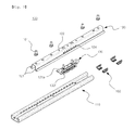
Fig. 1 is a perspective view of a seat track according to an exemplary embodiment of the present invention; -
Fig. 2 is a side view of the seat track ofFig. 1 ; -
Fig. 3 is an exploded perspective view the seat track ofFig. 1 ; -
Fig. 4 is an exploded perspective view of the locking member in the seat track ofFig. 3 ; -
Fig. 5 andFig. 6 are imaginary sectional views along AA line of the seat track ofFig. 2 and show a locking state and an unlocking state respectively; and -
Fig. 7 is a schematic view showing a locking process where the locking member is locked to the fixed rail according to a detail movement of the moving rail in the seat track ofFig. 1 . - As shown in
Fig. 1 andFig. 2 , theseat track 100 according to the exemplary embodiment of the present invention comprises afixed rail 110 fixed to a vehicle body and having a channel structure, and a movingrail 120 fixed to a seat through a combiningbolt 101 and located at an inner side of thefixed rail 110 to slide longitudinally along thefixed rail 110. - Also, the
seat track 100 comprises alocking member 130 shown inFig. 3 as means for locking and unlocking a slide of the movingrail 120 with regard to the fixedrail 110. - In
Fig. 3 , thenumeral 102 indicates a ball bearing and a bearing holder which are disposed between thefixed rail 110 and the movingrail 120 when therails - The
fixed rail 110 has at laterallyinner walls 112 extending vertically a number ofrecesses 112 which are provided with a predetermined pitch therebetween in the longitudinal direction. Therecesses 112 are formed to correspond laterally between theinner walls 112. - The moving
rail 120 is coupled to thefixed rail 110 at the inner side of thefixed rail 110 to slide longitudinally so that the laterallyvertical walls 121 face laterallyinner walls 111 of thefixed rail 110. - As shown in
Fig. 3 , eachvertical wall 121 has at its longitudinally center part a plurality of throughholes 124 formed at a predetermined interval therebetween. - As will be described later, rotating pins 133' of the
locking member 130 protrude through the throughholes 124 to be inserted into therecesses 112 of the fixedrail 110. - As shown in
Fig. 4 , thelocking member 130 has a supportingbody 131, a plurality of the rotatingpins 133 penetrated and rotatably supported by ahinge shaft 132 which is inserted into the supportingbody 131, aguide spring 134 elastically pressing the rotatingpins 133, and anunlocking body 135 guided by the supportingbody 131 in a vertical direction to operate the rotatingpins 133 to rotate. - The supporting
body 131 is received between the laterally vertical walls 121 (refer toFig. 3 ) of the movingrail 120 and it is installed and fixed at an inside of the movingrail 120 by combining combiningholes 131a formed on an upper surface at both ends thereof to combiningholes 122 of the movingrail 120. - Each of the rotating
pins 133 has apin hole 133a at its end part. Thehinge shaft 132 is inserted into thepin hole 133a, so that each rotatingpin 133 can rotate freely around thehinge shaft 132. - In the
seat track 100 according to this embodiment of the present invention, a plurality of the rotatingpins 133 are provided eight pieces per each lateral side to rotate with regard to the supportingbody 131 in the opposite directions therebetween. - In this case, the left rotating pins 133' and the right rotating
pins 133 are arrayed alternately therebetween along the longitudinal direction of the supportingbody 131. That is, the relation where the left rotating pin 133' is located at the front (left inFig. 4 ) and the right rotatingpin 133 is located next to it is maintained throughout the whole rotatingpins 133 and 133'. - In this embodiment, a plurality of
chamber walls 131b are formed in the supportingbody 131 along its longitudinal direction. - The left rotating pin 133' and the right rotating
pin 133 are received in a pair in each of eight compartments S formed by thechamber walls 131b. - This structure where the left and the right rotating
pins 133 and 133' are faced to each other and received in a pair can contribute to a decrease of the minimum slide interval, that is pitch, to lock the movingrail 120 with regard to thefixed rail 110. - If the pitch becomes smaller, the seat integrally slid with the moving
rail 120 can be fixed nearer to the position the user wants. - The
guide spring 134 has aguide body 134a of a shape of a stripe extending along a lateral surface of the supportingbody 131. Theguide body 134a is inserted in aslit 131a of the supportingbody 131. A plurality ofspring arms 134b extending from theguide body 134a elastically press the rotatingpins 133 upwardly. - Accordingly, the rotating
pins 133 are maintained to be rotated upwardly by thespring arms 134b if there is no outer force. - The
unlocking body 135 has a surface plate 135a extending in the longitudinal direction of the supportingbody 131 and eightpush arms 135b extending downwardly from both lateral side of the surface plate 135a. - In this case, the
push arms 135b of both lateral sides protrude to cross paths therebetween in order to correspond one to one to each of the rotatingpins 133, 133'. - The
unlocking body 135 slides up and down while a plurality of thepush arms 135b are guided by a plurality of guidingrecesses 131c which are formed at both lateral sides of the supportingbody 131. - An
input pin 135c is coupled onto the surface plate 135a of the unlockingbody 135 to protrude to an outside through an opening 123 of the moving rail 120 (refer toFig. 1 ). - Hereinafter, the operation of the
seat track 100 as described above is described. -
Fig. 5 andFig. 6 are imaginary sectional views of theseat track 100 along line AA inFig. 2 .Fig. 5 shows the rotating pin 133' located at a locking position andFig. 6 shows the rotating pin 133' at an unlocking position. - Referring to
Fig. 5 andFig. 6 , thelocking member 130 according to this exemplary embodiment of the present invention is disposed within the movingrail 120 except a part of the rotatingpins 133, 133'. - To describe the locking state of
Fig. 5 , the rotating pin 133', which is not pressed downwardly by thepush arm 135b of theunlocking body 135, is elastically pressed upwardly by thespring arm 134b of the guide spring to be maintained rotated counterclockwise to a locking position. - Accordingly, the rotating pin 133' protrudes through the
through hole 124 of the movingrail 120 to be inserted into therecess 112 of thefixed rail 110 so that the movingrail 120 is in the locking state with regard to thefixed rail 110. -
Fig. 6 shows an unlocking state. If the unlockingbody 135 is lowered by an outer force through theinput pin 135c, the rotating pin 133' is maintained rotated clockwise to an unlocking position due to the pressure of thepush arm 135b. - Accordingly, the rotating pin 133' is rotated and separated from the
recess 112 of the fixedrail 110, so that the movingrail 120 is in the unlocking state with regard to the fixedrail 110. - As described above, the
seat track 100 according to this exemplary embodiment of the present invention comprises a plurality of thechamber walls 131b in the supporting body 131 (refer toFig. 4 ) and a pair of the left and the rightrotating pins 133 and 133' are received for eachchamber wall 131b. - According to this disposition structure of the
rotating pins 133 and 133', the left rotating pin 133' and the rightrotating pin 133 are located within thesame chamber wall 131b to contact surface to surface therebetween. That is, as shown inFig. 7 , bothpin 133' and 133 within the same chamber wall are located very close to each other in the longitudinal direction while they operate with therecess 112 of the fixedrail 110. - In
Fig. 7 (a) , two left rotating pins 133'-2 and 133'-4 contact the front and rear surfaces of therecesses 112 to make locking, and two right rotating pins 133-2 and 133-8 contact the front and rear surfaces of therecesses 112 to make locking. Therefore, the movingrail 120 is locked with regard to the fixedrail 110. - If the moving
rail 120 is disposed to the left, the rotatingpins 133 and 133' moves integrally to the left as shown inFig. 7 (b) . in this condition, Either of the left and the rightrotating pins 133, 133' does not contact the front or the rear surface of therecess 112 thus making the unlocking sate. - If the
rotating pins 133 and 133' mover further to the left as shown inFig. 7 (c) , two left rotating pins 133'-1 and 133'-7 contact the front and rear surfaces of therecesses 112 to make locking, two right rotating pins 133-5 and 133-7 contact the front and rear surfaces of therecesses 112 to make locking. Therefore, the movingrail 120 is locked with regard to the fixedrail 110. - If the
rotating pins 133 and 133' mover further to the left as shown inFig. 7 (d) , either of the left and the rightrotating pins 133, 133' does not contact the front or the rear surface of therecess 112 thus making the unlocking sate. - If the
rotating pins 133 and 133' mover even further to the left as shown inFig. 7 (e) , two left rotating pins 133'-4 and 133'-6 contact the front and rear surfaces of therecesses 112 to make locking, two right rotating pins 133-2 and 133-4 contact the front and rear surfaces of therecesses 112 to make locking. Therefore, the movingrail 120 is locked with regard to the fixedrail 110. - According to the process as described above, the
seat track 100 of this exemplary embodiment of the present invention has the movingrail 120 whose minimum slide interval to make its locking state, that is the pitch, is the same as the distance that therotating pins 133, 133' have moved fromFig. 7 (a) to Fig. 7 (c) or fromFig. 7 (c) to Fig. 7 (e) . - This means that the user of the seat can adjust the longitudinal position of the seat per the interval from
Fig. 7 (a) to Fig. 7 (c) or fromFig. 7 (c) to Fig. 7 (e) , which also means the positional adjustment can be made per quite smaller interval compared to the conventional art. - Furthermore, even the states shown in
Fig. 7 (b) and (d) can be regarded as the locking state between therails rotating pins 133, 133' exist within therecesses 112 while they are movable a little back and forth. That is, according to the present invention, even if there is a gap between therecesses 112 and therotating pins 133, 133' inserted therein, at least a fully unlocking sate where completely no rotatingpins 133, 133' are inserted into therecesses 112 can be prevented. Therefore, the movingrail 120 is prevented from sliding due to an outer force. - Although the
seat track 100 according to the exemplary embodiment of the present invention has been disclosed, various modifications, additions and substitutions are possible, without departing from the scope and spirit of the invention. Therefore, the above embodiment must be regarded as one example provided for description of the present invention, rather than to limit the present invention.
Claims (7)
- A seat track comprising:a fixed rail of a channel structure having laterally inner walls which extend vertically and have recesses with a predetermined interval in a longitudinal direction;a moving rail sliding along the fixed rail and having laterally vertical walls which face the inner walls of the fixed rail and have a plurality of through holes with a predetermined interval in the longitudinal direction; anda locking member having a supporting body received and installed between the vertical walls of the moving rail to face a plurality of the through holes, a plurality of rotating pins supported by the supporting body and rotating between a locking position where a plurality of the rotating pins are inserted in the recesses of the fixed rail through the through holes and an unlocking position where a plurality of the rotating pins are separated from the recesses, a guide spring supported by the supporting body and pressing a plurality of the rotating pins to rotate toward the unlocking position, and an unlocking body sliding along the supporting body due to an outer force to press a plurality of the rotating pins to rotate from the locking position to the unlocking position.
- The seat track according to claim 1, wherein a plurality of the rotating pins are provided as a pair at both lateral sides and supported by the supporting body to rotate in the opposite directions therebetween, and also provided to be inserted into the recesses of the inner walls of the fixed rail through the through holes of the vertical walls of the moving rail.
- The seat track according to claim 2, wherein a plurality of the rotating pins which are provided as a pair at both lateral sides are penetrated and supported to rotate by a pair of hinge shaft inserted in the supporting body in the longitudinal direction.
- The seat track according to claim 2, wherein the unlocking body has a plurality of push arms in a pair at both lateral sides to correspond to each of a plurality of the rotating pins, and
the supporting body has a plurality of guiding recesses at both lateral sides to guide the slide of a plurality of the push arms. - The seat track according to claim 4, wherein the unlocking body has a surface plate received between the vertical walls of the moving rail as well as above the supporting body and integrally formed with a plurality of the push arms, and an input pin mounted on the surface plate to protrude to an outside through an upper surface of the moving rail.
- The seat track according to claim 2, wherein a plurality of the rotating pins are arrayed alternately along the longitudinal direction of the supporting body therebetween at both lateral sides, and
the supporting body has a plurality of chamber walls to receive a plurality of the rotating pins per two rotating pins from different lateral sides therebetween in the longitudinal direction. - The seat track according to claim 1, wherein the guide spring has a guide body of a stripe shape extending along a side surface of the supporting body, and a plurality of spring arms extending from the guide body to press a plurality of the rotating pins respectively.
Applications Claiming Priority (2)
| Application Number | Priority Date | Filing Date | Title |
|---|---|---|---|
| KR1020110037030A KR101206802B1 (en) | 2011-04-21 | 2011-04-21 | Seat track |
| PCT/KR2011/008945 WO2012144710A1 (en) | 2011-04-21 | 2011-11-23 | Seat track |
Publications (2)
| Publication Number | Publication Date |
|---|---|
| EP2700535A1 true EP2700535A1 (en) | 2014-02-26 |
| EP2700535A4 EP2700535A4 (en) | 2014-10-15 |
Family
ID=47041782
Family Applications (1)
| Application Number | Title | Priority Date | Filing Date |
|---|---|---|---|
| EP11864063.0A Withdrawn EP2700535A4 (en) | 2011-04-21 | 2011-11-23 | Seat track |
Country Status (9)
| Country | Link |
|---|---|
| US (1) | US9067514B2 (en) |
| EP (1) | EP2700535A4 (en) |
| KR (1) | KR101206802B1 (en) |
| CN (1) | CN103492224B (en) |
| BR (1) | BR112013026692A2 (en) |
| CA (1) | CA2832181C (en) |
| MX (1) | MX2013012227A (en) |
| RU (1) | RU2600967C2 (en) |
| WO (1) | WO2012144710A1 (en) |
Cited By (3)
| Publication number | Priority date | Publication date | Assignee | Title |
|---|---|---|---|---|
| DE102014220476B4 (en) | 2014-08-07 | 2019-06-19 | Adient Luxembourg Holding S.À R.L. | Longitudinal adjuster with locking mechanism |
| DE102020129031A1 (en) | 2020-11-04 | 2022-05-05 | Sitech Sp. Z O.O. | Locking mechanism for a seat rail |
| WO2024015033A1 (en) * | 2022-07-13 | 2024-01-18 | Özkiliç Otomoti̇v Ve Koltuk Si̇stemleri̇ Sanayi̇ Ti̇caret Li̇mi̇ted Şi̇rketi̇ | Rail mechanism used in vehicle seats |
Families Citing this family (35)
| Publication number | Priority date | Publication date | Assignee | Title |
|---|---|---|---|---|
| US9415701B2 (en) * | 2011-08-26 | 2016-08-16 | Magna Seating Inc. | Positively engaged latch for seat adjuster assembly |
| CN204236266U (en) * | 2011-10-17 | 2015-04-01 | 费舍尔和同伴有限公司 | Seat track assemblies |
| US10266074B2 (en) * | 2011-10-17 | 2019-04-23 | Fisher & Company, Incorporated | Seat-track assembly |
| JP5949282B2 (en) * | 2012-07-30 | 2016-07-06 | アイシン精機株式会社 | Vehicle seat slide device |
| KR101381577B1 (en) * | 2012-11-28 | 2014-04-07 | 현대다이모스(주) | Locking device for seat rail of vehicle |
| USD754521S1 (en) * | 2012-12-28 | 2016-04-26 | Thk Co., Ltd. | Vehicle seat rail |
| JP6217501B2 (en) * | 2014-02-05 | 2017-10-25 | トヨタ紡織株式会社 | Slide rail |
| US20160083098A1 (en) * | 2014-09-24 | 2016-03-24 | Gulfstream Aerospace Corporation | Aircraft and seat track assemblies for vibration isolation of floor mounted components |
| DE102014225426B4 (en) * | 2014-10-20 | 2022-01-13 | Adient Luxembourg Holding S.À R.L. | Longitudinal adjuster for a vehicle seat and vehicle seat |
| JP6471610B2 (en) * | 2015-05-26 | 2019-02-20 | トヨタ紡織株式会社 | Slide rail |
| JP6520542B2 (en) * | 2015-08-06 | 2019-05-29 | アイシン精機株式会社 | Seat slide device for vehicle |
| JP6589574B2 (en) * | 2015-11-06 | 2019-10-16 | アイシン精機株式会社 | Seat slide device for vehicle |
| US11214374B2 (en) * | 2016-08-01 | 2022-01-04 | Gulfstream Aerospace Corporation | Seat track assemblies for vibration isolation of floor mounted components |
| JP6911393B2 (en) | 2017-03-07 | 2021-07-28 | トヨタ紡織株式会社 | Seat slide device |
| US10470728B2 (en) * | 2017-03-21 | 2019-11-12 | General Electric Company | Orbital rotation positioning device for a C-arm of an imaging system |
| US11065986B2 (en) * | 2017-07-14 | 2021-07-20 | Adient Engineering and IP GmbH | Longitudinal adjuster for a vehicle seat, and vehicle seat |
| WO2019048519A1 (en) * | 2017-09-06 | 2019-03-14 | Adient Engineering and IP GmbH | Actuation mechanism for a longitudinal adjuster, longitudinal adjuster for a vehicle seat, and vehicle seat |
| KR101991344B1 (en) * | 2018-03-15 | 2019-06-20 | 주식회사 오스템 | Locking system of long rail for vehicle seat |
| US10926667B2 (en) * | 2018-05-04 | 2021-02-23 | Lear Corporation | Track assembly |
| IT201800005731A1 (en) * | 2018-05-25 | 2019-11-25 | Slider for a vehicle seat | |
| IT201800006569A1 (en) * | 2018-06-21 | 2019-12-21 | Sliding device for a vehicle seat having an improved locking system | |
| IT201800006650A1 (en) | 2018-06-26 | 2019-12-26 | Sliding device for a vehicle seat having an improved locking system | |
| JP7017490B2 (en) * | 2018-09-27 | 2022-02-08 | トヨタ自動車株式会社 | Vehicle seat structure |
| CN113056388B (en) * | 2018-10-19 | 2023-04-07 | 麦格纳座椅公司 | Removable seat for use with long track assembly |
| US11254241B2 (en) * | 2018-12-18 | 2022-02-22 | Tf-Metal Co., Ltd. | Seat sliding device for vehicles |
| KR102613446B1 (en) | 2018-12-20 | 2023-12-13 | 현대트랜시스 주식회사 | Seat track mechanism for vehicle seat |
| US11807142B2 (en) | 2019-03-06 | 2023-11-07 | Lear Corporation | Electrical track assembly |
| JP7387137B2 (en) * | 2019-07-31 | 2023-11-28 | デルタ工業株式会社 | seat slide adjuster |
| CN114829193A (en) * | 2019-12-20 | 2022-07-29 | 提爱思科技股份有限公司 | Slide locking structure for slide rail device |
| US11225173B2 (en) | 2020-02-12 | 2022-01-18 | Fisher & Company, Incorporated | Seat-track assembly |
| US11835119B2 (en) | 2020-02-21 | 2023-12-05 | Lear Corporation | Track system with a support member |
| US11505141B2 (en) | 2020-10-23 | 2022-11-22 | Lear Corporation | Electrical system with track assembly and support assembly |
| US11708011B2 (en) | 2021-03-05 | 2023-07-25 | Camaco, Llc. | Reinforced track assembly for vehicle seat |
| US11718204B2 (en) * | 2021-03-05 | 2023-08-08 | Camaco, Llc. | Anti-chuck mechanism for seat track assembly |
| WO2023074692A1 (en) * | 2021-10-26 | 2023-05-04 | テイ・エス テック株式会社 | Sliding lock device and method of assembling sliding device |
Citations (2)
| Publication number | Priority date | Publication date | Assignee | Title |
|---|---|---|---|---|
| DE10040593A1 (en) * | 2000-08-16 | 2002-03-07 | Keiper Gmbh & Co | Locking mechanism for car seat mounted on rails which slide in guide rails comprises catches mounted on swivel bearings on seat rails whose axis is parallel to the rails and which are spring loaded to engage in slots in guide rails |
| JP2008149923A (en) * | 2006-12-19 | 2008-07-03 | Shiroki Corp | Lock mechanism for seat track |
Family Cites Families (15)
| Publication number | Priority date | Publication date | Assignee | Title |
|---|---|---|---|---|
| US5918846A (en) * | 1996-12-11 | 1999-07-06 | Meritor Automotive Canada, Inc. | Seat track with continuous engagement and memory easy entry mechanism |
| US6354553B1 (en) * | 2000-03-01 | 2002-03-12 | Dura Global Technologies, Inc. | Seat track assembly with positive lock mechanism |
| KR100366577B1 (en) * | 2000-10-26 | 2003-01-09 | 현대자동차주식회사 | Seat track locking structure for automobile |
| DE50211631D1 (en) | 2001-11-28 | 2008-03-20 | Hammerstein Gmbh C Rob | Locking device with several locking pins |
| US6869057B2 (en) * | 2002-12-20 | 2005-03-22 | Fuji Kiko Co., Ltd. | Seat slide device |
| KR100512889B1 (en) * | 2003-05-27 | 2005-09-07 | 주식회사 오스템 | Locking device of seat-track for vehicles |
| JP2005007982A (en) | 2003-06-18 | 2005-01-13 | Fuji Kiko Co Ltd | Seat slide unit for vehicle |
| JP4433925B2 (en) | 2004-07-27 | 2010-03-17 | アイシン精機株式会社 | Seat slide device |
| JP4984471B2 (en) * | 2005-09-29 | 2012-07-25 | アイシン精機株式会社 | Vehicle seat slide device |
| JP4986036B2 (en) * | 2007-04-05 | 2012-07-25 | トヨタ紡織株式会社 | Vehicle seat slide mechanism |
| KR100848004B1 (en) * | 2007-10-09 | 2008-07-23 | 주식회사 오스템 | Seat moving track assembly |
| US8215602B2 (en) * | 2008-05-23 | 2012-07-10 | Lear Corporation | Longitudinal adjustment apparatus for a vehicle seat |
| JP5164671B2 (en) | 2008-05-29 | 2013-03-21 | 富士機工株式会社 | Vehicle seat slide device |
| WO2010080597A1 (en) * | 2008-12-19 | 2010-07-15 | Lear Corporation | Adjustable seat track with zero chuck lock |
| KR101048162B1 (en) | 2009-03-25 | 2011-07-08 | 주식회사 오스템 | Sheet conveying track device |
-
2011
- 2011-04-21 KR KR1020110037030A patent/KR101206802B1/en active IP Right Grant
- 2011-11-23 CA CA2832181A patent/CA2832181C/en not_active Expired - Fee Related
- 2011-11-23 US US14/111,867 patent/US9067514B2/en not_active Expired - Fee Related
- 2011-11-23 RU RU2013151809/11A patent/RU2600967C2/en not_active IP Right Cessation
- 2011-11-23 WO PCT/KR2011/008945 patent/WO2012144710A1/en active Application Filing
- 2011-11-23 CN CN201180070261.5A patent/CN103492224B/en not_active Expired - Fee Related
- 2011-11-23 EP EP11864063.0A patent/EP2700535A4/en not_active Withdrawn
- 2011-11-23 MX MX2013012227A patent/MX2013012227A/en unknown
- 2011-11-23 BR BR112013026692A patent/BR112013026692A2/en not_active IP Right Cessation
Patent Citations (2)
| Publication number | Priority date | Publication date | Assignee | Title |
|---|---|---|---|---|
| DE10040593A1 (en) * | 2000-08-16 | 2002-03-07 | Keiper Gmbh & Co | Locking mechanism for car seat mounted on rails which slide in guide rails comprises catches mounted on swivel bearings on seat rails whose axis is parallel to the rails and which are spring loaded to engage in slots in guide rails |
| JP2008149923A (en) * | 2006-12-19 | 2008-07-03 | Shiroki Corp | Lock mechanism for seat track |
Non-Patent Citations (1)
| Title |
|---|
| See also references of WO2012144710A1 * |
Cited By (3)
| Publication number | Priority date | Publication date | Assignee | Title |
|---|---|---|---|---|
| DE102014220476B4 (en) | 2014-08-07 | 2019-06-19 | Adient Luxembourg Holding S.À R.L. | Longitudinal adjuster with locking mechanism |
| DE102020129031A1 (en) | 2020-11-04 | 2022-05-05 | Sitech Sp. Z O.O. | Locking mechanism for a seat rail |
| WO2024015033A1 (en) * | 2022-07-13 | 2024-01-18 | Özkiliç Otomoti̇v Ve Koltuk Si̇stemleri̇ Sanayi̇ Ti̇caret Li̇mi̇ted Şi̇rketi̇ | Rail mechanism used in vehicle seats |
Also Published As
| Publication number | Publication date |
|---|---|
| CN103492224B (en) | 2016-03-02 |
| BR112013026692A2 (en) | 2016-12-27 |
| CN103492224A (en) | 2014-01-01 |
| MX2013012227A (en) | 2013-11-01 |
| RU2600967C2 (en) | 2016-10-27 |
| WO2012144710A1 (en) | 2012-10-26 |
| KR101206802B1 (en) | 2012-11-30 |
| RU2013151809A (en) | 2015-05-27 |
| US9067514B2 (en) | 2015-06-30 |
| US20140224954A1 (en) | 2014-08-14 |
| CA2832181A1 (en) | 2012-10-26 |
| EP2700535A4 (en) | 2014-10-15 |
| KR20120119240A (en) | 2012-10-31 |
| CA2832181C (en) | 2016-05-17 |
Similar Documents
| Publication | Publication Date | Title |
|---|---|---|
| EP2700535A1 (en) | Seat track | |
| US7780138B1 (en) | Seat moving track assembly | |
| RU2375534C1 (en) | Multi-function lock | |
| EP2593330B1 (en) | Seat track locking system for vehicle | |
| CN101130347B (en) | Seat slide apparatus for vehicle | |
| EP3254890B1 (en) | Manual type seat cushion extension device and vehicle seat comprising the same | |
| US11535125B2 (en) | Manufacturing method of lower rail of seat slider device | |
| KR101477581B1 (en) | Lock mechanism for seat track slide device | |
| CN107009919A (en) | Seat rail for vehicle with unblock release lever | |
| TWI487467B (en) | Hinge assembly having linear movement and slide type electronic device | |
| WO2008157314A1 (en) | Lock cylinder with locking member | |
| EP3167755B1 (en) | Drawer slide assembly | |
| KR101352762B1 (en) | Seat track | |
| KR101615523B1 (en) | Vehicle seat track having locking system | |
| US20040087212A1 (en) | Card slot assembly with means for preventing insertion of erroneous card having thickness smaller than correct card | |
| CN109421554A (en) | Vehicle seat used adjusting guide rail | |
| KR102013303B1 (en) | Locking mechanism for vehicle seat slide | |
| JP2006168688A (en) | Seat slide device for vehicle | |
| CN2787500Y (en) | Automobile seat track mechanism | |
| CN218448580U (en) | ISOFIX connector | |
| JP7450562B2 (en) | seat sliding device | |
| JP5014286B2 (en) | Vending machine door lock mechanism | |
| CN209443965U (en) | Dual contact is tiltedly locked | |
| JP4595088B2 (en) | Locking device | |
| CN117302036A (en) | Console box |
Legal Events
| Date | Code | Title | Description |
|---|---|---|---|
| PUAI | Public reference made under article 153(3) epc to a published international application that has entered the european phase |
Free format text: ORIGINAL CODE: 0009012 |
|
| 17P | Request for examination filed |
Effective date: 20131121 |
|
| AK | Designated contracting states |
Kind code of ref document: A1 Designated state(s): AL AT BE BG CH CY CZ DE DK EE ES FI FR GB GR HR HU IE IS IT LI LT LU LV MC MK MT NL NO PL PT RO RS SE SI SK SM TR |
|
| DAX | Request for extension of the european patent (deleted) | ||
| A4 | Supplementary search report drawn up and despatched |
Effective date: 20140915 |
|
| RIC1 | Information provided on ipc code assigned before grant |
Ipc: B60N 2/08 20060101AFI20140909BHEP Ipc: B60N 2/06 20060101ALI20140909BHEP |
|
| GRAP | Despatch of communication of intention to grant a patent |
Free format text: ORIGINAL CODE: EPIDOSNIGR1 |
|
| INTG | Intention to grant announced |
Effective date: 20170111 |
|
| STAA | Information on the status of an ep patent application or granted ep patent |
Free format text: STATUS: THE APPLICATION IS DEEMED TO BE WITHDRAWN |
|
| 18D | Application deemed to be withdrawn |
Effective date: 20170523 |