EP2700129B1 - Connector element having second contact securing means - Google Patents
Connector element having second contact securing means Download PDFInfo
- Publication number
- EP2700129B1 EP2700129B1 EP12712673.8A EP12712673A EP2700129B1 EP 2700129 B1 EP2700129 B1 EP 2700129B1 EP 12712673 A EP12712673 A EP 12712673A EP 2700129 B1 EP2700129 B1 EP 2700129B1
- Authority
- EP
- European Patent Office
- Prior art keywords
- securing
- contact
- connector element
- locking
- insertion direction
- Prior art date
- Legal status (The legal status is an assumption and is not a legal conclusion. Google has not performed a legal analysis and makes no representation as to the accuracy of the status listed.)
- Active
Links
Images

Classifications
-
- H—ELECTRICITY
- H01—ELECTRIC ELEMENTS
- H01R—ELECTRICALLY-CONDUCTIVE CONNECTIONS; STRUCTURAL ASSOCIATIONS OF A PLURALITY OF MUTUALLY-INSULATED ELECTRICAL CONNECTING ELEMENTS; COUPLING DEVICES; CURRENT COLLECTORS
- H01R13/00—Details of coupling devices of the kinds covered by groups H01R12/70 or H01R24/00 - H01R33/00
- H01R13/40—Securing contact members in or to a base or case; Insulating of contact members
- H01R13/42—Securing in a demountable manner
- H01R13/424—Securing in base or case composed of a plurality of insulating parts having at least one resilient insulating part
-
- H—ELECTRICITY
- H01—ELECTRIC ELEMENTS
- H01R—ELECTRICALLY-CONDUCTIVE CONNECTIONS; STRUCTURAL ASSOCIATIONS OF A PLURALITY OF MUTUALLY-INSULATED ELECTRICAL CONNECTING ELEMENTS; COUPLING DEVICES; CURRENT COLLECTORS
- H01R13/00—Details of coupling devices of the kinds covered by groups H01R12/70 or H01R24/00 - H01R33/00
- H01R13/40—Securing contact members in or to a base or case; Insulating of contact members
- H01R13/42—Securing in a demountable manner
- H01R13/422—Securing in resilient one-piece base or case, e.g. by friction; One-piece base or case formed with resilient locking means
- H01R13/4223—Securing in resilient one-piece base or case, e.g. by friction; One-piece base or case formed with resilient locking means comprising integral flexible contact retaining fingers
-
- H—ELECTRICITY
- H01—ELECTRIC ELEMENTS
- H01R—ELECTRICALLY-CONDUCTIVE CONNECTIONS; STRUCTURAL ASSOCIATIONS OF A PLURALITY OF MUTUALLY-INSULATED ELECTRICAL CONNECTING ELEMENTS; COUPLING DEVICES; CURRENT COLLECTORS
- H01R13/00—Details of coupling devices of the kinds covered by groups H01R12/70 or H01R24/00 - H01R33/00
- H01R13/40—Securing contact members in or to a base or case; Insulating of contact members
- H01R13/42—Securing in a demountable manner
- H01R13/436—Securing a plurality of contact members by one locking piece or operation
- H01R13/4361—Insertion of locking piece perpendicular to direction of contact insertion
-
- H—ELECTRICITY
- H01—ELECTRIC ELEMENTS
- H01R—ELECTRICALLY-CONDUCTIVE CONNECTIONS; STRUCTURAL ASSOCIATIONS OF A PLURALITY OF MUTUALLY-INSULATED ELECTRICAL CONNECTING ELEMENTS; COUPLING DEVICES; CURRENT COLLECTORS
- H01R13/00—Details of coupling devices of the kinds covered by groups H01R12/70 or H01R24/00 - H01R33/00
- H01R13/46—Bases; Cases
- H01R13/50—Bases; Cases formed as an integral body
- H01R13/501—Bases; Cases formed as an integral body comprising an integral hinge or a frangible part
Definitions
- the present invention relates to an electrical connector element, in particular as part of an electrical plug type connector, having at least one contact receiving member for an electrical contact element which can be inserted into the at least one contact receiving member in an insertion direction as far as its end position, having a locking member by means of which the contact element in its locking position can be secured in the end position against being removed from the at least one contact receiving member counter to the insertion direction, and having a securing member which retains the locking member in the locking position in its securing position, wherein the securing member in the securing position at least partially protrudes into the at least one contact receiving member in order to additionally secure the contact element against being removed from the at least one contact receiving member counter to the insertion direction, wherein a catch element on a securing position of the securing member in the securing position is able to engage with a counter-catch element of the connector element that adjoins the at least one contact receiving member and wherein the securing member has a locking face which is constructed to secure the electrical contact element against being
- JP S62 55880 U and JP H09 147953 A all disclose an electrical connector with a chamber for receiving a terminal secured by a latching element at a first edge of the terminal and a securing member which secures the latching element.
- EP 1 176 670 A1 and EP 1 408 588 A1 describes an electrical connector with a chamber for receiving a terminal secured by a latching element at a first edge of the terminal and a securing member which secures the latching element as well as sits behind a second edge of the terminal, distance from the edge in an insertion direction.
- US 2006/0052004 A1 describes a housing of a connector accommodating a terminal which similar to the teachings of EP 1 176 670 A1 is secured by a latch of the housing and additionally by a retainer in different regions along the insertion direction.
- DE 42 05 974 C1 discloses a plug connector having a main housing formed as a moulding of insulating material including a chamber formed to receive a pin, with the pin having a flange section. As the pin is inserted into the housing, an elastic arm is deflected and has a leading edge that engages the flange to provide retention.
- An interlock element is formed as part of the housing and is integrally coupled by a thin film section. The interlock element can be turned through 90 degrees for a hole to locate over a lug on the arm.
- a disadvantage with connector elements known from the prior art is that an additional, so-called second contact securing means, which supplements the contact primary engagement brought about by the locking members and may help to check correct seating of the contact elements in their end positions, is possible only with difficulty.
- an object of the present invention is to better protect the contact elements from being removed from the contact receiving members and to facilitate checking of correct seating of the contact elements in their end position.
- the contact element can additionally be secured directly to the securing member.
- a fixing or securing of the contact element in the end position that supplements the securing of the contact element by the securing member can be achieved.
- the securing member can perform an additional function, by acting as a second contact securing means. Furthermore, the position of the contact element can be checked using the securing member.
- the securing member may also help to secure the primary engagement brought about by the securing member. It is further possible to increase contact removal forces required to pull the contact elements out counter to the insertion direction, for example, by reaching behind a retention portion of the contact elements, the so-called contact box.
- the retention portion or the contact box may, for example, be used both by the locking member and by the securing member in order to secure the contact element.
- the securing member may thus be provision according to a first advantageous embodiment for the securing member to extend in the securing position at least partially through an aperture into the at least one contact receiving member and to overlap therewith in a projection in the insertion direction.
- the securing member Via the aperture, the securing member can be moved into the contact receiving member in a particularly simple manner and, for example, extend from outside the connector element through the aperture laterally and/or from above into the contact receiving member.
- the aperture may thus provide lateral and/or vertical access to the contact receiving member. Owing to the overlapping with the contact receiving member, the cross-section thereof may be reduced at any desired location in such a manner that, in the region of the cross-section reduction, the contact element is blocked.
- a blocking or additional locking of the contact element in the end position can be produced in a simple manner by the securing member, at least in the securing position, protruding into the at least one contact receiving member counter to a vertical direction extending transversely relative to the insertion direction and/or in a transverse direction of the connector element extending both transversely relative to the vertical direction and transversely relative to the insertion direction.
- a lateral support means that an actuation path or resilient path of the locking member extends substantially parallel with the vertical direction and the locking member is supported transversely relative to the actuation path. Consequently, the locking member can be secured against lateral movements, or laterally retained, which increases the rigidity of the locking and helps to prevent damage to the locking member.
- the locking member and retention member may be arranged at the same height in the insertion direction.
- the securing member or the securing portion thereof may be arranged, for example, slightly offset in the insertion direction upstream of the locking member so that the securing member is carried only when the locking member fails.
- the catch element may, for example, be formed on or as a securing portion of the securing member which may, for example, have a hold-down member for the locking member, a locking face for the contact element, a catch projection and/or a blocking element for preventing premature assembly of connector elements which are not correctly provided with contact elements.
- the securing member may, at least in the securing position, be in alignment with an outer wall portion of the connector element.
- portions of the securing member which protrude from the connector element can consequently be prevented from becoming damaged or making the handling thereof more difficult.
- a portion of the securing member that acts as a blocking element may protrude above the wall portion in a preliminary securing position in order to prevent premature assembly of connector elements which are not correctly provided with contact elements. In the securing position, this blocking element may be embedded in the connector element in such a manner that it allows assembly of the connector element and mating connector element.
- Another possibility for protecting the securing member or the securing thereof to the connector element from damage involves a portion of the connector element for fitting the securing member being directed in the insertion direction and/or extending transversely relative to an outer wall portion of the connector element. Consequently, optionally when handling the connector element, in particular when a blocking element of the securing member in the preliminary securing position prevents assembly with a mating connector, forces acting on the connection can be better transmitted from the securing member to the housing member.
- the securing member may advantageously be connected to the housing member in a simple manner by being hinged thereto. This allows the securing member to be fitted to the housing member in a non-releasable manner.
- the securing member and housing member may also be constructed integrally in this manner.
- the hinge may be protected from damage by the securing member being connected to the connector element at a face of the connector element which is directed substantially in an insertion direction and/or in a connection direction of the connector element.
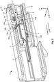
- the structure of a connector element 1 according to the invention will first be explained with reference to the schematic, perspective cross-section thereof shown in Figure 1 .
- the connector element 1 has a housing member 2.
- An insertion portion 3 and a conductor receiving portion 4 are formed on the housing member 2.
- the insertion portion 3 is constructed so as to be able to be connected to a mating connector portion of a mating connector element (not shown).
- the connector element 1 and the mating connector element may be part of an electrical plug type connector.
- a mating connector receiving member 6 which is accessible via an insertion opening 5 is formed in the insertion portion 3.
- two plug type contacts 101 in the form of pin contacts which are formed in each case on a contact element 100.
- the plug type contacts 101 extend substantially parallel with an insertion direction S of the connector element 1 which extends in the present embodiment substantially parallel with a longitudinal direction X of the contact element 1.
- a transverse direction Y of the connector element that extends transversely to the longitudinal direction X two contact elements 100 are arranged beside each other in the present example.
- the longitudinal direction X and transverse direction Y both extend substantially transversely relative to a vertical direction Z of the connector element 1.
- the contact elements 100 are each retained in a contact receiving member 7 which is formed in the conductor receiving portion 4. To this end, a retention portion 102 is formed in each case on the contact elements 100. Furthermore, the contact elements 100 each have a conductor securing portion 103 for securing an electrical conductor (not illustrated) to the contact element 100. Via a contact insertion opening 8, the contact element 100 can be inserted into its contact receiving member 7 in an insertion direction E which extends substantially parallel with the longitudinal direction X with the plug type contact 101 at the front. The retention portion 102 passes a locking member 9 of the connector element 1.
- the locking member 9 protrudes into the contact receiving member 7 in a locking position L transversely relative to the longitudinal extent of the contact receiving member 7 that extends substantially parallel with the longitudinal direction X, in the present case counter to the vertical direction Z.
- the locking member 9 is redirected in the vertical direction Z owing to resilient securing to the connector element in the region of a lower member 10 of the locking member 9.
- the locking zone 12 comprises a catch portion 12a and a hold-down portion 12b.
- the catch portion 12a is formed as a catch projection whose catch face 12a which is directed substantially in the insertion direction E abuts an engagement region 102a of the contact element 100 that is formed on the retention portion 102 and is directed substantially counter to the insertion direction E in an end position F of the contact element 100 shown in Figure 1 .
- the engagement region 102a is formed as a face or corner on the retention portion 102.
- a hold-down face 12b on the hold-down portion 12b is, at least in the end position F, arranged in a vertical direction Z above a hold-down region 102b that is formed on the retention portion 102.
- the connector element 1 has a securing member 13 which can be secured as in the present case to the conductor receiving portion 4.
- the securing member 13 has an actuation portion 14 and a securing portion 15.
- the actuation portion 14 in the form of a type of lever, whose outer side provides an actuation face for applying an actuation force, is secured to a face 17 which is formed on the housing member 2 by means of a lower member of the securing member 13 intended to form a hinge 16 and which is directed substantially in the connection and insertion direction S or E.
- the securing member 13 is connected in a rotationally movable manner to the housing member 2 by means of the hinge 16.
- the securing portion 15 can be moved along a substantially circular actuation path W from the preliminary securing position A of the securing member 13 which is shown here and in which the securing portion 15 is moved out of engagement with the contact receiving member 7, into a securing position B (see Figures 2 and 3 ) of the securing member 13.
- the face 17 is formed on a continuation 18 which extends in a vertical direction Z away from the housing member 2.
- the securing portion 15 is fitted to the actuation portion 14 so as to bend substantially at a right angle from the actuation portion 14 so that the securing portion 15 can extend away from the actuation portion 14 counter to the vertical direction Z as soon as it extends substantially parallel with the longitudinal direction X in the securing position B.
- the securing portion 15 comprises a catch element 15a and a hold-down member 15b.
- the catch element 15a carries out a dual function in that it has a locking face 15c and a catch projection 15d.
- the locking face 15c is constructed to sit in the securing position B in the insertion direction E upstream of the engagement region 102a of the contact element 100 in order, in addition to the catch face 12c, to be able to secure the contact element 100 against movements counter to the insertion direction E.
- the catch projection 15d is in turn constructed so as to co-operate with a counter-catch element (not yet illustrated in this instance) on the housing member in order to engage the securing member 13 in the securing position B.
- the securing portion 15 provides a blocking element 15e in the form of a surface which may prevent complete connection of the connector element 1 with a mating connector element as long as the securing member 13 is in the preliminary securing position A.
- the mating connector element may, for example, be constructed in such a manner that an interrogation region, for example, an edge of a mating connector opening, strikes the blocking element 15e as long as it is not moved into the securing position B. This may signal, for example, that the contact element 100 has not been moved completely into the end position F, whereby the locking zone 12 could be moved upwards out of the contact receiving member 7. Consequently, the hold-down member 15b would rest on an actuation face 12e of the locking zone 12 or be blocked thereby and prevent a movement of the securing member 13 from the preliminary securing position A into the securing position B.
- Figure 2 illustrates the connector element 1 with two contact elements 100 which are each in the end position F and which are locked in their contact receiving members 7 by means of the locking members 9.
- the locking members 9 are secured by the securing member 13 which has been moved from the preliminary securing position A into the securing position B in the locking position L.
- the hold-down member 15b rests on the actuation face 12e or is at least arranged with small spacing therefrom and consequently prevents the locking member 9 from being moved upwards out of the locking position L.
- the securing member 13 secures the locking members 9 in each case laterally in the transverse direction Y by the two catch elements 15a which are formed as securing members 13 each being arranged next to the locking members 9.
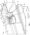
- Figure 3 illustrates how one of the two catch elements 15a is arranged beside one of the locking members 9.
- the securing portion 15 thus protrudes with the catch element 15a into an aperture 20 which extends from outside the housing member 2 into the contact receiving member 7.
- the aperture 20 is provided with an inclined starting member 21.
- the inclined starting member 21 facilitates movement of the securing member 13 from the preliminary securing position A into the securing position B by the catch projection 15d being guided along the inclined starting member, the securing portion 15 being resiliently redirected until the catch projection 15d snap-fits at the lower end of the inclined starting member into a counter-catch element 22 in the form of a catch opening formed on the housing member 2 and secures the securing member 9 in the securing position B by means of engagement.
- the portion of the securing portion 15 that forms the catch element 15a is pushed beside the locking member 9 in the locking position L. Parallel with the transverse direction Y, the locking member 9 is now locked between the securing portion 15 and a partition wall 23.
- the partition wall 23 is formed on the housing member 2 and separates the two contact receiving members 7 from each other.
- the locking face 15c is arranged in the insertion direction E upstream of the engagement region 102a of the contact element 100 and, in addition to the catch face 12c of the locking member 9, prevents the contact element 100 from being pulled counter to the insertion direction E from its contact receiving member 7.
- the actuation portion 14 of the securing member 13 is in alignment in the securing position B with an upper wall portion 24 of the housing member. That is to say, the actuation portion 14 is received in a recess 25 on the housing member.
- the insertion portion 3 may have the requirements in accordance with a connector opening 5 and a mating connector receiving member 6 or, for example, be formed as a connector for insertion.
- the contact elements may form the pin contacts or socket contacts illustrated in this instance as plug type contacts 101.
- the conductor receiving portion 4 may have any number of contact receiving members 7 with contact insertion openings 8 which are formed so as to fit respective contact elements 100. Consequently, the number of locking members 9 may vary in accordance with the number of contact receiving members 7.
- the locking members 9 may be formed in accordance with the respective requirements and be resiliently connected to the housing member 2 by means of lower members 10.
- the securing member 13 may be adapted to the configuration of the locking members 9. It is advantageous for the securing member 13 to be constructed as illustrated herein to secure a plurality of locking receiving members 9 by protecting them, together with its hold-down member 15b, against movements in the vertical direction Z and laterally fixing or securing them at the same time with two portions of its securing portion 15 that are arranged at both sides of the locking members 9, for example, as shown in this instance, by the catch elements 15a. It is further advantageous, but not absolutely necessary, for the contact receiving members 7, the locking members 9 and the securing member 13 to be integrally formed on the housing member 2, that is to say, as integral components thereof.
- a configuration according to the invention of a connector element 1 is not limited to the 180° variant described herein, but can also be used with angled connectors in which, for example, the insertion direction E is bent counter to the connection direction S.
Landscapes
- Connector Housings Or Holding Contact Members (AREA)
- Details Of Connecting Devices For Male And Female Coupling (AREA)
Description
- The present invention relates to an electrical connector element, in particular as part of an electrical plug type connector, having at least one contact receiving member for an electrical contact element which can be inserted into the at least one contact receiving member in an insertion direction as far as its end position, having a locking member by means of which the contact element in its locking position can be secured in the end position against being removed from the at least one contact receiving member counter to the insertion direction, and having a securing member which retains the locking member in the locking position in its securing position, wherein the securing member in the securing position at least partially protrudes into the at least one contact receiving member in order to additionally secure the contact element against being removed from the at least one contact receiving member counter to the insertion direction, wherein a catch element on a securing position of the securing member in the securing position is able to engage with a counter-catch element of the connector element that adjoins the at least one contact receiving member and wherein the securing member has a locking face which is constructed to secure the electrical contact element against being removed from the at least one contact receiving member counter to the insertion direction, wherein the locking member has a catch face formed as a catch projection which in the securing position is directed in the insertion direction and is configured to abut an engagement region, said engagement region being formed as a face or corner on a retention portion of the at least one contact element and being directed counter to the insertion direction, wherein the locking face of the securing portion of the securing member in the securing position is configured to be arranged in the end position in the insertion direction upstream of the engagement region of the retention portion securing the contact element, in addition to the catch face, against movement counter to the insertion direction, so the engagement region of the retention portion is used both by the locking member and by the securing member in order to secure the contact element.
- Such connector elements are known from the prior art. For example, the specification
US 6,024,605 discloses an "inline" connector element, that is to say, a so-called 180° connector, in which locking members in the form of resiliently deflectable catches or catch plates are retained in their locking position by means of a cover which is connected to a housing member of the connector element by means of a type of integral hinge. - Furthermore, the specification
US 5,100,345 A discloses a connector element of the generic type, in which catch members for the contact elements are secured in the locking position by means of a cover which is constructed so as to be able to be displaceably fitted to the housing member. -
US 2009/053916 A1 ,JP S62 55880 U JP H09 147953 A -
EP 1 176 670 A1EP 1 408 588 A1 -
US 2006/0052004 A1 describes a housing of a connector accommodating a terminal which similar to the teachings ofEP 1 176 670 A1 -
DE 42 05 974 C1 discloses a plug connector having a main housing formed as a moulding of insulating material including a chamber formed to receive a pin, with the pin having a flange section. As the pin is inserted into the housing, an elastic arm is deflected and has a leading edge that engages the flange to provide retention. An interlock element is formed as part of the housing and is integrally coupled by a thin film section. The interlock element can be turned through 90 degrees for a hole to locate over a lug on the arm. - A disadvantage with connector elements known from the prior art is that an additional, so-called second contact securing means, which supplements the contact primary engagement brought about by the locking members and may help to check correct seating of the contact elements in their end positions, is possible only with difficulty.
Taking into account these disadvantages, an object of the present invention is to better protect the contact elements from being removed from the contact receiving members and to facilitate checking of correct seating of the contact elements in their end position. - This object is achieved according to the invention in that the catch element has the locking face.
- That is to say, the contact element can additionally be secured directly to the securing member. A fixing or securing of the contact element in the end position that supplements the securing of the contact element by the securing member can be achieved.
- This solution has the advantage that the securing member can perform an additional function, by acting as a second contact securing means. Furthermore, the position of the contact element can be checked using the securing member. The securing member may also help to secure the primary engagement brought about by the securing member. It is further possible to increase contact removal forces required to pull the contact elements out counter to the insertion direction, for example, by reaching behind a retention portion of the contact elements, the so-called contact box. The retention portion or the contact box may, for example, be used both by the locking member and by the securing member in order to secure the contact element.
- The solution according to the invention can be freely combined and further improved with the following additional embodiments which are each advantageous per se.
- There may thus be provision according to a first advantageous embodiment for the securing member to extend in the securing position at least partially through an aperture into the at least one contact receiving member and to overlap therewith in a projection in the insertion direction. Via the aperture, the securing member can be moved into the contact receiving member in a particularly simple manner and, for example, extend from outside the connector element through the aperture laterally and/or from above into the contact receiving member. The aperture may thus provide lateral and/or vertical access to the contact receiving member. Owing to the overlapping with the contact receiving member, the cross-section thereof may be reduced at any desired location in such a manner that, in the region of the cross-section reduction, the contact element is blocked.
- A blocking or additional locking of the contact element in the end position can be produced in a simple manner by the securing member, at least in the securing position, protruding into the at least one contact receiving member counter to a vertical direction extending transversely relative to the insertion direction and/or in a transverse direction of the connector element extending both transversely relative to the vertical direction and transversely relative to the insertion direction.
- Depending on the orientation of an actuation path of the locking member, there may be provision for the securing member in the securing position to laterally support the locking member transversely relative to the insertion direction. In the present instance, a lateral support means that an actuation path or resilient path of the locking member extends substantially parallel with the vertical direction and the locking member is supported transversely relative to the actuation path. Consequently, the locking member can be secured against lateral movements, or laterally retained, which increases the rigidity of the locking and helps to prevent damage to the locking member.
- It is not absolutely necessary in this instance for the locking member and retention member to be arranged at the same height in the insertion direction. Alternatively, the securing member or the securing portion thereof may be arranged, for example, slightly offset in the insertion direction upstream of the locking member so that the securing member is carried only when the locking member fails.
- The catch element may, for example, be formed on or as a securing portion of the securing member which may, for example, have a hold-down member for the locking member, a locking face for the contact element, a catch projection and/or a blocking element for preventing premature assembly of connector elements which are not correctly provided with contact elements.
- The securing member may, at least in the securing position, be in alignment with an outer wall portion of the connector element. On the one hand, portions of the securing member which protrude from the connector element can consequently be prevented from becoming damaged or making the handling thereof more difficult. On the other hand, a portion of the securing member that acts as a blocking element may protrude above the wall portion in a preliminary securing position in order to prevent premature assembly of connector elements which are not correctly provided with contact elements. In the securing position, this blocking element may be embedded in the connector element in such a manner that it allows assembly of the connector element and mating connector element.
- Another possibility for protecting the securing member or the securing thereof to the connector element from damage involves a portion of the connector element for fitting the securing member being directed in the insertion direction and/or extending transversely relative to an outer wall portion of the connector element. Consequently, optionally when handling the connector element, in particular when a blocking element of the securing member in the preliminary securing position prevents assembly with a mating connector, forces acting on the connection can be better transmitted from the securing member to the housing member.
- The securing member may advantageously be connected to the housing member in a simple manner by being hinged thereto. This allows the securing member to be fitted to the housing member in a non-releasable manner. The securing member and housing member may also be constructed integrally in this manner.
- In particular when the securing member is hinged to the housing member, the hinge may be protected from damage by the securing member being connected to the connector element at a face of the connector element which is directed substantially in an insertion direction and/or in a connection direction of the connector element.
- The invention is described in greater detail below by way of example with reference to possible embodiments and the appended drawings. The feature combinations illustrated in those embodiments are intended merely for purposes of illustration. Individual features may also be omitted in accordance with their advantages described above if the advantage of this feature is not important in specific applications. In the drawings:
-
Figure 1 is a schematic, perspective cross-section of a connector element according to the invention having a securing member in a preliminary securing position; -
Figure 2 is a schematic, perspective cross-section of the connector element illustrated inFigure 1 with the securing member in a securing position; and -
Figure 3 is a schematic, perspective detailed view of the connector element shown inFigures 1 and2 , which is partially sectioned in the region of engagement of the securing member in a contact receiving member of the connector element. - The structure of a
connector element 1 according to the invention will first be explained with reference to the schematic, perspective cross-section thereof shown inFigure 1 . Theconnector element 1 has ahousing member 2. Aninsertion portion 3 and aconductor receiving portion 4 are formed on thehousing member 2. Theinsertion portion 3 is constructed so as to be able to be connected to a mating connector portion of a mating connector element (not shown). Theconnector element 1 and the mating connector element may be part of an electrical plug type connector. - A mating
connector receiving member 6 which is accessible via aninsertion opening 5 is formed in theinsertion portion 3. In the matingconnector receiving member 6 there are arranged twoplug type contacts 101 in the form of pin contacts which are formed in each case on acontact element 100. Theplug type contacts 101 extend substantially parallel with an insertion direction S of theconnector element 1 which extends in the present embodiment substantially parallel with a longitudinal direction X of thecontact element 1. In a transverse direction Y of the connector element that extends transversely to the longitudinal direction X, twocontact elements 100 are arranged beside each other in the present example. The longitudinal direction X and transverse direction Y both extend substantially transversely relative to a vertical direction Z of theconnector element 1. - The
contact elements 100 are each retained in acontact receiving member 7 which is formed in theconductor receiving portion 4. To this end, aretention portion 102 is formed in each case on thecontact elements 100. Furthermore, thecontact elements 100 each have aconductor securing portion 103 for securing an electrical conductor (not illustrated) to thecontact element 100. Via acontact insertion opening 8, thecontact element 100 can be inserted into itscontact receiving member 7 in an insertion direction E which extends substantially parallel with the longitudinal direction X with theplug type contact 101 at the front. Theretention portion 102 passes alocking member 9 of theconnector element 1. - The locking
member 9 protrudes into thecontact receiving member 7 in a locking position L transversely relative to the longitudinal extent of thecontact receiving member 7 that extends substantially parallel with the longitudinal direction X, in the present case counter to the vertical direction Z. During the introduction of thecontact element 100, the lockingmember 9 is redirected in the vertical direction Z owing to resilient securing to the connector element in the region of alower member 10 of the lockingmember 9. For ease of redirection, there is formed on the locking member 9 a slightly inclined leadingmember 11 which extends substantially from thelower member 10 to alocking zone 12 of the lockingmember 9. - The locking
zone 12 comprises acatch portion 12a and a hold-downportion 12b. Thecatch portion 12a is formed as a catch projection whosecatch face 12a which is directed substantially in the insertion direction E abuts anengagement region 102a of thecontact element 100 that is formed on theretention portion 102 and is directed substantially counter to the insertion direction E in an end position F of thecontact element 100 shown inFigure 1 . Theengagement region 102a is formed as a face or corner on theretention portion 102. A hold-downface 12b on the hold-downportion 12b is, at least in the end position F, arranged in a vertical direction Z above a hold-downregion 102b that is formed on theretention portion 102. By the hold-downregion 102b being arranged below the hold-downportion 12b, which may abut the hold-downregion 102b or at least be arranged in the vicinity thereof, thecontact element 100 is fixed or secured in the vertical direction Z. - Furthermore, the
connector element 1 has a securingmember 13 which can be secured as in the present case to theconductor receiving portion 4. The securingmember 13 has anactuation portion 14 and a securingportion 15. Theactuation portion 14 in the form of a type of lever, whose outer side provides an actuation face for applying an actuation force, is secured to aface 17 which is formed on thehousing member 2 by means of a lower member of the securingmember 13 intended to form ahinge 16 and which is directed substantially in the connection and insertion direction S or E.The securing member 13 is connected in a rotationally movable manner to thehousing member 2 by means of thehinge 16. Consequently, the securingportion 15 can be moved along a substantially circular actuation path W from the preliminary securing position A of the securingmember 13 which is shown here and in which the securingportion 15 is moved out of engagement with thecontact receiving member 7, into a securing position B (seeFigures 2 and3 ) of the securingmember 13. Theface 17 is formed on acontinuation 18 which extends in a vertical direction Z away from thehousing member 2. - The securing
portion 15 is fitted to theactuation portion 14 so as to bend substantially at a right angle from theactuation portion 14 so that the securingportion 15 can extend away from theactuation portion 14 counter to the vertical direction Z as soon as it extends substantially parallel with the longitudinal direction X in the securing position B. The securingportion 15 comprises acatch element 15a and a hold-down member 15b. Thecatch element 15a carries out a dual function in that it has a lockingface 15c and acatch projection 15d. The lockingface 15c is constructed to sit in the securing position B in the insertion direction E upstream of theengagement region 102a of thecontact element 100 in order, in addition to thecatch face 12c, to be able to secure thecontact element 100 against movements counter to the insertion direction E. Thecatch projection 15d is in turn constructed so as to co-operate with a counter-catch element (not yet illustrated in this instance) on the housing member in order to engage the securingmember 13 in the securing position B. - Furthermore, the securing
portion 15 provides a blockingelement 15e in the form of a surface which may prevent complete connection of theconnector element 1 with a mating connector element as long as the securingmember 13 is in the preliminary securing position A. To this end, the mating connector element may, for example, be constructed in such a manner that an interrogation region, for example, an edge of a mating connector opening, strikes the blockingelement 15e as long as it is not moved into the securing position B. This may signal, for example, that thecontact element 100 has not been moved completely into the end position F, whereby the lockingzone 12 could be moved upwards out of thecontact receiving member 7. Consequently, the hold-down member 15b would rest on anactuation face 12e of the lockingzone 12 or be blocked thereby and prevent a movement of the securingmember 13 from the preliminary securing position A into the securing position B. -
Figure 2 illustrates theconnector element 1 with twocontact elements 100 which are each in the end position F and which are locked in theircontact receiving members 7 by means of thelocking members 9. The lockingmembers 9 are secured by the securingmember 13 which has been moved from the preliminary securing position A into the securing position B in the locking position L. In order to secure thelocking members 9 in the locking position L, the hold-down member 15b rests on theactuation face 12e or is at least arranged with small spacing therefrom and consequently prevents the lockingmember 9 from being moved upwards out of the locking position L. In addition, the securingmember 13 secures thelocking members 9 in each case laterally in the transverse direction Y by the twocatch elements 15a which are formed as securingmembers 13 each being arranged next to thelocking members 9. -
Figure 3 illustrates how one of the twocatch elements 15a is arranged beside one of thelocking members 9. The securingportion 15 thus protrudes with thecatch element 15a into anaperture 20 which extends from outside thehousing member 2 into thecontact receiving member 7. Theaperture 20 is provided with an inclined startingmember 21. The inclined startingmember 21 facilitates movement of the securingmember 13 from the preliminary securing position A into the securing position B by thecatch projection 15d being guided along the inclined starting member, the securingportion 15 being resiliently redirected until thecatch projection 15d snap-fits at the lower end of the inclined starting member into acounter-catch element 22 in the form of a catch opening formed on thehousing member 2 and secures the securingmember 9 in the securing position B by means of engagement. The portion of the securingportion 15 that forms thecatch element 15a is pushed beside the lockingmember 9 in the locking position L. Parallel with the transverse direction Y, the lockingmember 9 is now locked between the securingportion 15 and apartition wall 23. Thepartition wall 23 is formed on thehousing member 2 and separates the twocontact receiving members 7 from each other. - Furthermore, the locking
face 15c is arranged in the insertion direction E upstream of theengagement region 102a of thecontact element 100 and, in addition to thecatch face 12c of the lockingmember 9, prevents thecontact element 100 from being pulled counter to the insertion direction E from itscontact receiving member 7. Furthermore, theactuation portion 14 of the securingmember 13 is in alignment in the securing position B with anupper wall portion 24 of the housing member. That is to say, theactuation portion 14 is received in arecess 25 on the housing member. - In the context of the notion of the invention, deviations from the embodiments described above are possible. For instance, the
insertion portion 3 may have the requirements in accordance with aconnector opening 5 and a matingconnector receiving member 6 or, for example, be formed as a connector for insertion. The contact elements may form the pin contacts or socket contacts illustrated in this instance asplug type contacts 101. Theconductor receiving portion 4 may have any number ofcontact receiving members 7 withcontact insertion openings 8 which are formed so as to fitrespective contact elements 100. Consequently, the number of lockingmembers 9 may vary in accordance with the number ofcontact receiving members 7. The lockingmembers 9 may be formed in accordance with the respective requirements and be resiliently connected to thehousing member 2 by means oflower members 10. - The securing
member 13 may be adapted to the configuration of thelocking members 9. It is advantageous for the securingmember 13 to be constructed as illustrated herein to secure a plurality of locking receivingmembers 9 by protecting them, together with its hold-down member 15b, against movements in the vertical direction Z and laterally fixing or securing them at the same time with two portions of its securingportion 15 that are arranged at both sides of thelocking members 9, for example, as shown in this instance, by thecatch elements 15a. It is further advantageous, but not absolutely necessary, for thecontact receiving members 7, the lockingmembers 9 and the securingmember 13 to be integrally formed on thehousing member 2, that is to say, as integral components thereof. - A configuration according to the invention of a
connector element 1 is not limited to the 180° variant described herein, but can also be used with angled connectors in which, for example, the insertion direction E is bent counter to the connection direction S. -
- 1 Connector element
- 2 Housing member
- 3 Connector portion
- 4 Conductor receiving portion
- 5 Insertion opening
- 6 Mating connector receiving member Conductor fixing portion
- 7 Contact receiving member
- 8 Contact insertion opening
- 9 Locking member
- 10 Lower member of the locking member
- 11 Inclined leading member
- 12 Locking zone
- 12a Catch portion
- 12b Hold-down portion
- 12c Catch face
- 12d Hold-down face
- 12e Actuation face
- 13 Securing member
- 14 Actuation portion
- 15 Securing portion
- 15a Catch element
- 15b Hold-down member
- 15c Locking face
- 15d Catch projection
- 15e Blocking element
- 16 Hinge
- 17 Surface
- 18 Continuation
- 20 Aperture
- 21 Inclined starting member
- 22 Counter-catch element
- 23 Partition wall
- 24 Upper wall portion
- 25 Recess
- 100 Contact element
- 101 Insertion contact
- 102 Retention portion
- 102a Engagement region
- 102b Hold-down region
- 103
- A Preliminary securing position
- B Securing position
- E Insertion direction
- F End position
- L Locking position
- S Connection direction
- W Actuation path
- X Longitudinal direction
- Y Transverse direction
- Z Vertical direction
Claims (8)
- Electrical connector element (1) having at least one contact receiving member (7) for an electrical contact element (100) which can be inserted into the at least one contact receiving member (7) in an insertion direction (E) as far as its end position (F), having a locking member (9) by means of which the contact element (100) in its locking position (L) can be secured in the end position (F) against being removed from the at least one contact receiving member (7) counter to the insertion direction (E), and having a securing member (13) which retains the locking member (9) in the locking position (L) in its securing position (B), wherein the securing member (13) in the securing position (B), in order to additionally secure the contact element (100) against being removed from the at least one contact receiving member (7) counter to the insertion direction (E), at least partially protrudes into the at least one contact receiving member (7), wherein a catch element (15a) on a securing portion (15) of the securing member (13) in the securing position (B) is able to engage with a counter-catch element (22) of the connector element (1) that adjoins the at least one contact receiving member (7), and wherein the securing member (13) has a locking face (15c) which is constructed to secure the electrical contact element (100) against being removed from the at least one contact receiving member (7) counter to the insertion direction (E), wherein the locking member (9) has a catch face (12a) formed as a catch projection which in the securing position (B) is directed in the insertion direction (E) and is configured to abut an engagement region (102a), said engagement region (102a) being formed as a face or corner on a retention portion (102) of the at least one contact element (100) and being directed counter to the insertion direction (E), wherein the locking face (15c) of the securing portion (15) of the securing member (13) in the securing position (B) is configured to be arranged in the end position (F) in the insertion direction (E) upstream of the engagement region (102a) of the retention portion (102) securing the contact element (100), in addition to the catch face (12c), against movement counter to the insertion direction (E), so the engagement region (102a) of the retention portion (102) is used both by the locking member (9) and by the securing member (13) in order to secure the contact element (100), characterized in that the catch element (15a) has the locking face (15c).
- Electrical connector element (1) according to claim 1, characterised in that the securing member (13) extends in the securing position (B) at least partially through an aperture (20) into the at least one contact receiving member (7) and overlaps with the at least one contact receiving member (7) in a projection in the insertion direction (E).
- Electrical connector element (1) according to claim 1 or 2, characterised in that the securing member (13) at least in the securing position (B) protrudes into the at least one contact receiving member (7) counter to a vertical direction (Z) extending transversely relative to the insertion direction (E) and/or in a transverse direction (Y) of the connector element (1) extending both transversely relative to the vertical direction (Z) and transversely relative to the insertion direction (E).
- Electrical connector element (1) according to any one of claims 1 to 3, characterised in that the securing member (13) in the securing position (B) laterally supports the locking member (9) transversely relative to the insertion direction (E).
- Electrical connector element (1) according to any one of claims 1 to 4, characterised in that the securing member (13) at least in the securing position (B) is in alignment with an outer wall portion (24) of the connector element (1).
- Electrical connector element (1) according to any one of claims 1 to 5, characterised in that a portion of the connector element (1) for fitting the securing member (13) is directed in the insertion direction (E).
- Electrical connector element (1) according to any one of claims 1 to 6, characterised in that the securing member (13) is hinged to a housing member (2) of the connector element (1).
- Electrical connector element (1) according to any one of claims 1 to 7, characterised in that the securing member (13) is connected to the connector element (1) at a surface (17) of the connector element (1) which is directed substantially in or counter to the insertion direction (E) and/or in a connection direction (S) of the connector element (1).
Applications Claiming Priority (2)
| Application Number | Priority Date | Filing Date | Title |
|---|---|---|---|
| DE102011002135A DE102011002135B4 (en) | 2011-04-18 | 2011-04-18 | Plug element with second contact fuse |
| PCT/EP2012/056441 WO2012143259A1 (en) | 2011-04-18 | 2012-04-10 | Connector element having second contact securing means |
Publications (2)
| Publication Number | Publication Date |
|---|---|
| EP2700129A1 EP2700129A1 (en) | 2014-02-26 |
| EP2700129B1 true EP2700129B1 (en) | 2018-05-23 |
Family
ID=45932343
Family Applications (1)
| Application Number | Title | Priority Date | Filing Date |
|---|---|---|---|
| EP12712673.8A Active EP2700129B1 (en) | 2011-04-18 | 2012-04-10 | Connector element having second contact securing means |
Country Status (6)
| Country | Link |
|---|---|
| US (1) | US9093770B2 (en) |
| EP (1) | EP2700129B1 (en) |
| JP (1) | JP2014514719A (en) |
| CN (1) | CN103620878B (en) |
| DE (1) | DE102011002135B4 (en) |
| WO (1) | WO2012143259A1 (en) |
Families Citing this family (6)
| Publication number | Priority date | Publication date | Assignee | Title |
|---|---|---|---|---|
| EP2846416B1 (en) * | 2013-08-23 | 2020-02-12 | TE Connectivity India Private Limited | Connector housing with a monolithically integrated terminal positioning assurance device |
| USD750804S1 (en) * | 2013-08-30 | 2016-03-01 | Vkr Holding A/S | Connector element for use in a flashing assembly for roof windows |
| DE202014004431U1 (en) * | 2014-05-27 | 2014-06-12 | Rosenberger Hochfrequenztechnik Gmbh & Co. Kg | Contact holding part with secured train protection |
| JP6088472B2 (en) * | 2014-09-04 | 2017-03-01 | 矢崎総業株式会社 | connector |
| CH714248B1 (en) * | 2017-10-16 | 2023-03-15 | Landis & Gyr Ag | Multi-part housing for consumption meter and safety device for multi-part housing. |
| US11201428B2 (en) * | 2019-09-27 | 2021-12-14 | Aptiv Technologies Limited | Connector assembly with connector lock and terminal retainer |
Citations (5)
| Publication number | Priority date | Publication date | Assignee | Title |
|---|---|---|---|---|
| JPS6255880U (en) * | 1985-09-27 | 1987-04-07 | ||
| DE4205974C1 (en) * | 1992-02-27 | 1993-06-24 | Leopold Kostal Gmbh & Co Kg, 5880 Luedenscheid, De | Electrical plug connector with built-in latching for pins - provides section formed on housing that locates against pin flange and is held by latch stage |
| JPH09147953A (en) * | 1995-11-20 | 1997-06-06 | Sumitomo Wiring Syst Ltd | Connector |
| EP1408588A1 (en) * | 2002-10-09 | 2004-04-14 | Delphi Technologies, Inc. | Electrical connector |
| US20090053916A1 (en) * | 2007-08-21 | 2009-02-26 | Yazaki Corporation | Connector |
Family Cites Families (10)
| Publication number | Priority date | Publication date | Assignee | Title |
|---|---|---|---|---|
| JPH079343Y2 (en) | 1990-04-10 | 1995-03-06 | 矢崎総業株式会社 | Connector with terminal locking device |
| JP2581487Y2 (en) * | 1993-09-16 | 1998-09-21 | 住友電装株式会社 | connector |
| IT1268609B1 (en) * | 1994-09-30 | 1997-03-06 | Framatome Connectors Italia | ELECTRIC CONNECTOR |
| IT1267649B1 (en) * | 1994-12-16 | 1997-02-07 | Framatome Connectors Italia | ELECTRIC CONNECTOR. |
| US6024605A (en) | 1997-12-19 | 2000-02-15 | The Whitaker Corporation | Electrical connector with interlocking living hinge |
| ATE251348T1 (en) * | 2000-07-29 | 2003-10-15 | Whitaker Corp | ELECTRICAL CONNECTOR AND HOUSING FOR SUCH AN ELECTRICAL CONNECTOR |
| JP4047731B2 (en) * | 2003-01-10 | 2008-02-13 | 三菱電線工業株式会社 | Electrical connector |
| JP4356567B2 (en) | 2004-09-09 | 2009-11-04 | 住友電装株式会社 | connector |
| WO2006108610A1 (en) * | 2005-04-11 | 2006-10-19 | Fci | Electrical connector |
| US7914327B2 (en) * | 2008-01-23 | 2011-03-29 | Fci Americas Technology, Inc. | Electrical connector |
-
2011
- 2011-04-18 DE DE102011002135A patent/DE102011002135B4/en not_active Expired - Fee Related
-
2012
- 2012-04-10 CN CN201280029969.0A patent/CN103620878B/en active Active
- 2012-04-10 EP EP12712673.8A patent/EP2700129B1/en active Active
- 2012-04-10 US US14/112,494 patent/US9093770B2/en active Active
- 2012-04-10 JP JP2014505571A patent/JP2014514719A/en active Pending
- 2012-04-10 WO PCT/EP2012/056441 patent/WO2012143259A1/en not_active Ceased
Patent Citations (5)
| Publication number | Priority date | Publication date | Assignee | Title |
|---|---|---|---|---|
| JPS6255880U (en) * | 1985-09-27 | 1987-04-07 | ||
| DE4205974C1 (en) * | 1992-02-27 | 1993-06-24 | Leopold Kostal Gmbh & Co Kg, 5880 Luedenscheid, De | Electrical plug connector with built-in latching for pins - provides section formed on housing that locates against pin flange and is held by latch stage |
| JPH09147953A (en) * | 1995-11-20 | 1997-06-06 | Sumitomo Wiring Syst Ltd | Connector |
| EP1408588A1 (en) * | 2002-10-09 | 2004-04-14 | Delphi Technologies, Inc. | Electrical connector |
| US20090053916A1 (en) * | 2007-08-21 | 2009-02-26 | Yazaki Corporation | Connector |
Also Published As
| Publication number | Publication date |
|---|---|
| JP2014514719A (en) | 2014-06-19 |
| EP2700129A1 (en) | 2014-02-26 |
| US9093770B2 (en) | 2015-07-28 |
| DE102011002135A1 (en) | 2012-10-18 |
| CN103620878A (en) | 2014-03-05 |
| WO2012143259A1 (en) | 2012-10-26 |
| CN103620878B (en) | 2017-06-13 |
| DE102011002135B4 (en) | 2012-12-13 |
| US20140045363A1 (en) | 2014-02-13 |
Similar Documents
| Publication | Publication Date | Title |
|---|---|---|
| US9979131B2 (en) | Electrical connector assembly with improved locking device | |
| EP2929599B1 (en) | Electrical connector and assembly therewith having a spring-apart function | |
| US9093770B2 (en) | Connector element having second contact securing means | |
| EP3248251B1 (en) | Plug-type connector systems | |
| US9059540B2 (en) | Electrical connector assembly, and connector for such assembly | |
| EP1073153B1 (en) | Connector | |
| KR20190074949A (en) | Power connector and power connector apparatus | |
| EP2783428B1 (en) | Lever type connector | |
| US20130330956A1 (en) | Joint Connector | |
| WO2014160995A1 (en) | Connector with tpa | |
| US9853391B2 (en) | Wire connector with integrated coaxial connection and front loaded terminal position assurance structures | |
| EP2051335B1 (en) | A connector | |
| US10511117B2 (en) | Connector | |
| KR102763337B1 (en) | Connector shielding with a guiding protrusion | |
| EP3288118B1 (en) | Electrical connector | |
| EP1801925A1 (en) | A connector | |
| EP3037304B1 (en) | Electrical junction box for vehicle | |
| EP2685570B1 (en) | Electrical plug-in connector assembly with locking member | |
| EP1916746B1 (en) | A connector | |
| EP2839547B1 (en) | Subassembly for an electrical plug type connector and kit | |
| CN107181130B (en) | Connector and connector structure | |
| WO2015114662A1 (en) | Multi function connector positioning assurance device | |
| WO2013149813A1 (en) | Electrical plug element with expandable contact securing device | |
| JP6128056B2 (en) | connector | |
| US20220059962A1 (en) | Connector |
Legal Events
| Date | Code | Title | Description |
|---|---|---|---|
| PUAI | Public reference made under article 153(3) epc to a published international application that has entered the european phase |
Free format text: ORIGINAL CODE: 0009012 |
|
| 17P | Request for examination filed |
Effective date: 20131118 |
|
| AK | Designated contracting states |
Kind code of ref document: A1 Designated state(s): AL AT BE BG CH CY CZ DE DK EE ES FI FR GB GR HR HU IE IS IT LI LT LU LV MC MK MT NL NO PL PT RO RS SE SI SK SM TR |
|
| DAX | Request for extension of the european patent (deleted) | ||
| 17Q | First examination report despatched |
Effective date: 20150430 |
|
| RAP1 | Party data changed (applicant data changed or rights of an application transferred) |
Owner name: TE CONNECTIVITY GERMANY GMBH |
|
| STAA | Information on the status of an ep patent application or granted ep patent |
Free format text: STATUS: EXAMINATION IS IN PROGRESS |
|
| RIC1 | Information provided on ipc code assigned before grant |
Ipc: H01R 13/436 20060101ALI20171115BHEP Ipc: H01R 13/422 20060101AFI20171115BHEP Ipc: H01R 13/50 20060101ALI20171115BHEP |
|
| GRAP | Despatch of communication of intention to grant a patent |
Free format text: ORIGINAL CODE: EPIDOSNIGR1 |
|
| STAA | Information on the status of an ep patent application or granted ep patent |
Free format text: STATUS: GRANT OF PATENT IS INTENDED |
|
| INTG | Intention to grant announced |
Effective date: 20180102 |
|
| GRAS | Grant fee paid |
Free format text: ORIGINAL CODE: EPIDOSNIGR3 |
|
| GRAA | (expected) grant |
Free format text: ORIGINAL CODE: 0009210 |
|
| STAA | Information on the status of an ep patent application or granted ep patent |
Free format text: STATUS: THE PATENT HAS BEEN GRANTED |
|
| AK | Designated contracting states |
Kind code of ref document: B1 Designated state(s): AL AT BE BG CH CY CZ DE DK EE ES FI FR GB GR HR HU IE IS IT LI LT LU LV MC MK MT NL NO PL PT RO RS SE SI SK SM TR |
|
| REG | Reference to a national code |
Ref country code: GB Ref legal event code: FG4D |
|
| REG | Reference to a national code |
Ref country code: CH Ref legal event code: EP |
|
| REG | Reference to a national code |
Ref country code: IE Ref legal event code: FG4D |
|
| REG | Reference to a national code |
Ref country code: AT Ref legal event code: REF Ref document number: 1002259 Country of ref document: AT Kind code of ref document: T Effective date: 20180615 |
|
| REG | Reference to a national code |
Ref country code: DE Ref legal event code: R096 Ref document number: 602012046582 Country of ref document: DE |
|
| REG | Reference to a national code |
Ref country code: NL Ref legal event code: MP Effective date: 20180523 |
|
| REG | Reference to a national code |
Ref country code: LT Ref legal event code: MG4D |
|
| PG25 | Lapsed in a contracting state [announced via postgrant information from national office to epo] |
Ref country code: SE Free format text: LAPSE BECAUSE OF FAILURE TO SUBMIT A TRANSLATION OF THE DESCRIPTION OR TO PAY THE FEE WITHIN THE PRESCRIBED TIME-LIMIT Effective date: 20180523 Ref country code: BG Free format text: LAPSE BECAUSE OF FAILURE TO SUBMIT A TRANSLATION OF THE DESCRIPTION OR TO PAY THE FEE WITHIN THE PRESCRIBED TIME-LIMIT Effective date: 20180823 Ref country code: LT Free format text: LAPSE BECAUSE OF FAILURE TO SUBMIT A TRANSLATION OF THE DESCRIPTION OR TO PAY THE FEE WITHIN THE PRESCRIBED TIME-LIMIT Effective date: 20180523 Ref country code: FI Free format text: LAPSE BECAUSE OF FAILURE TO SUBMIT A TRANSLATION OF THE DESCRIPTION OR TO PAY THE FEE WITHIN THE PRESCRIBED TIME-LIMIT Effective date: 20180523 Ref country code: NO Free format text: LAPSE BECAUSE OF FAILURE TO SUBMIT A TRANSLATION OF THE DESCRIPTION OR TO PAY THE FEE WITHIN THE PRESCRIBED TIME-LIMIT Effective date: 20180823 Ref country code: ES Free format text: LAPSE BECAUSE OF FAILURE TO SUBMIT A TRANSLATION OF THE DESCRIPTION OR TO PAY THE FEE WITHIN THE PRESCRIBED TIME-LIMIT Effective date: 20180523 |
|
| PG25 | Lapsed in a contracting state [announced via postgrant information from national office to epo] |
Ref country code: GR Free format text: LAPSE BECAUSE OF FAILURE TO SUBMIT A TRANSLATION OF THE DESCRIPTION OR TO PAY THE FEE WITHIN THE PRESCRIBED TIME-LIMIT Effective date: 20180824 Ref country code: HR Free format text: LAPSE BECAUSE OF FAILURE TO SUBMIT A TRANSLATION OF THE DESCRIPTION OR TO PAY THE FEE WITHIN THE PRESCRIBED TIME-LIMIT Effective date: 20180523 Ref country code: LV Free format text: LAPSE BECAUSE OF FAILURE TO SUBMIT A TRANSLATION OF THE DESCRIPTION OR TO PAY THE FEE WITHIN THE PRESCRIBED TIME-LIMIT Effective date: 20180523 Ref country code: NL Free format text: LAPSE BECAUSE OF FAILURE TO SUBMIT A TRANSLATION OF THE DESCRIPTION OR TO PAY THE FEE WITHIN THE PRESCRIBED TIME-LIMIT Effective date: 20180523 Ref country code: RS Free format text: LAPSE BECAUSE OF FAILURE TO SUBMIT A TRANSLATION OF THE DESCRIPTION OR TO PAY THE FEE WITHIN THE PRESCRIBED TIME-LIMIT Effective date: 20180523 |
|
| REG | Reference to a national code |
Ref country code: AT Ref legal event code: MK05 Ref document number: 1002259 Country of ref document: AT Kind code of ref document: T Effective date: 20180523 |
|
| PG25 | Lapsed in a contracting state [announced via postgrant information from national office to epo] |
Ref country code: RO Free format text: LAPSE BECAUSE OF FAILURE TO SUBMIT A TRANSLATION OF THE DESCRIPTION OR TO PAY THE FEE WITHIN THE PRESCRIBED TIME-LIMIT Effective date: 20180523 Ref country code: CZ Free format text: LAPSE BECAUSE OF FAILURE TO SUBMIT A TRANSLATION OF THE DESCRIPTION OR TO PAY THE FEE WITHIN THE PRESCRIBED TIME-LIMIT Effective date: 20180523 Ref country code: DK Free format text: LAPSE BECAUSE OF FAILURE TO SUBMIT A TRANSLATION OF THE DESCRIPTION OR TO PAY THE FEE WITHIN THE PRESCRIBED TIME-LIMIT Effective date: 20180523 Ref country code: AT Free format text: LAPSE BECAUSE OF FAILURE TO SUBMIT A TRANSLATION OF THE DESCRIPTION OR TO PAY THE FEE WITHIN THE PRESCRIBED TIME-LIMIT Effective date: 20180523 Ref country code: EE Free format text: LAPSE BECAUSE OF FAILURE TO SUBMIT A TRANSLATION OF THE DESCRIPTION OR TO PAY THE FEE WITHIN THE PRESCRIBED TIME-LIMIT Effective date: 20180523 Ref country code: PL Free format text: LAPSE BECAUSE OF FAILURE TO SUBMIT A TRANSLATION OF THE DESCRIPTION OR TO PAY THE FEE WITHIN THE PRESCRIBED TIME-LIMIT Effective date: 20180523 Ref country code: SK Free format text: LAPSE BECAUSE OF FAILURE TO SUBMIT A TRANSLATION OF THE DESCRIPTION OR TO PAY THE FEE WITHIN THE PRESCRIBED TIME-LIMIT Effective date: 20180523 |
|
| REG | Reference to a national code |
Ref country code: DE Ref legal event code: R097 Ref document number: 602012046582 Country of ref document: DE |
|
| PG25 | Lapsed in a contracting state [announced via postgrant information from national office to epo] |
Ref country code: IT Free format text: LAPSE BECAUSE OF FAILURE TO SUBMIT A TRANSLATION OF THE DESCRIPTION OR TO PAY THE FEE WITHIN THE PRESCRIBED TIME-LIMIT Effective date: 20180523 Ref country code: SM Free format text: LAPSE BECAUSE OF FAILURE TO SUBMIT A TRANSLATION OF THE DESCRIPTION OR TO PAY THE FEE WITHIN THE PRESCRIBED TIME-LIMIT Effective date: 20180523 |
|
| PLBE | No opposition filed within time limit |
Free format text: ORIGINAL CODE: 0009261 |
|
| STAA | Information on the status of an ep patent application or granted ep patent |
Free format text: STATUS: NO OPPOSITION FILED WITHIN TIME LIMIT |
|
| 26N | No opposition filed |
Effective date: 20190226 |
|
| PG25 | Lapsed in a contracting state [announced via postgrant information from national office to epo] |
Ref country code: SI Free format text: LAPSE BECAUSE OF FAILURE TO SUBMIT A TRANSLATION OF THE DESCRIPTION OR TO PAY THE FEE WITHIN THE PRESCRIBED TIME-LIMIT Effective date: 20180523 |
|
| PG25 | Lapsed in a contracting state [announced via postgrant information from national office to epo] |
Ref country code: AL Free format text: LAPSE BECAUSE OF FAILURE TO SUBMIT A TRANSLATION OF THE DESCRIPTION OR TO PAY THE FEE WITHIN THE PRESCRIBED TIME-LIMIT Effective date: 20180523 |
|
| REG | Reference to a national code |
Ref country code: CH Ref legal event code: PL |
|
| REG | Reference to a national code |
Ref country code: BE Ref legal event code: MM Effective date: 20190430 |
|
| GBPC | Gb: european patent ceased through non-payment of renewal fee |
Effective date: 20190410 |
|
| PG25 | Lapsed in a contracting state [announced via postgrant information from national office to epo] |
Ref country code: LU Free format text: LAPSE BECAUSE OF NON-PAYMENT OF DUE FEES Effective date: 20190410 Ref country code: MC Free format text: LAPSE BECAUSE OF FAILURE TO SUBMIT A TRANSLATION OF THE DESCRIPTION OR TO PAY THE FEE WITHIN THE PRESCRIBED TIME-LIMIT Effective date: 20180523 |
|
| PG25 | Lapsed in a contracting state [announced via postgrant information from national office to epo] |
Ref country code: GB Free format text: LAPSE BECAUSE OF NON-PAYMENT OF DUE FEES Effective date: 20190410 Ref country code: LI Free format text: LAPSE BECAUSE OF NON-PAYMENT OF DUE FEES Effective date: 20190430 Ref country code: CH Free format text: LAPSE BECAUSE OF NON-PAYMENT OF DUE FEES Effective date: 20190430 |
|
| PG25 | Lapsed in a contracting state [announced via postgrant information from national office to epo] |
Ref country code: BE Free format text: LAPSE BECAUSE OF NON-PAYMENT OF DUE FEES Effective date: 20190430 |
|
| PG25 | Lapsed in a contracting state [announced via postgrant information from national office to epo] |
Ref country code: TR Free format text: LAPSE BECAUSE OF FAILURE TO SUBMIT A TRANSLATION OF THE DESCRIPTION OR TO PAY THE FEE WITHIN THE PRESCRIBED TIME-LIMIT Effective date: 20180523 |
|
| PG25 | Lapsed in a contracting state [announced via postgrant information from national office to epo] |
Ref country code: IE Free format text: LAPSE BECAUSE OF NON-PAYMENT OF DUE FEES Effective date: 20190410 |
|
| PG25 | Lapsed in a contracting state [announced via postgrant information from national office to epo] |
Ref country code: PT Free format text: LAPSE BECAUSE OF FAILURE TO SUBMIT A TRANSLATION OF THE DESCRIPTION OR TO PAY THE FEE WITHIN THE PRESCRIBED TIME-LIMIT Effective date: 20180924 |
|
| PG25 | Lapsed in a contracting state [announced via postgrant information from national office to epo] |
Ref country code: CY Free format text: LAPSE BECAUSE OF FAILURE TO SUBMIT A TRANSLATION OF THE DESCRIPTION OR TO PAY THE FEE WITHIN THE PRESCRIBED TIME-LIMIT Effective date: 20180523 |
|
| PG25 | Lapsed in a contracting state [announced via postgrant information from national office to epo] |
Ref country code: IS Free format text: LAPSE BECAUSE OF FAILURE TO SUBMIT A TRANSLATION OF THE DESCRIPTION OR TO PAY THE FEE WITHIN THE PRESCRIBED TIME-LIMIT Effective date: 20180923 |
|
| PG25 | Lapsed in a contracting state [announced via postgrant information from national office to epo] |
Ref country code: MT Free format text: LAPSE BECAUSE OF FAILURE TO SUBMIT A TRANSLATION OF THE DESCRIPTION OR TO PAY THE FEE WITHIN THE PRESCRIBED TIME-LIMIT Effective date: 20180523 Ref country code: HU Free format text: LAPSE BECAUSE OF FAILURE TO SUBMIT A TRANSLATION OF THE DESCRIPTION OR TO PAY THE FEE WITHIN THE PRESCRIBED TIME-LIMIT; INVALID AB INITIO Effective date: 20120410 |
|
| PG25 | Lapsed in a contracting state [announced via postgrant information from national office to epo] |
Ref country code: MK Free format text: LAPSE BECAUSE OF FAILURE TO SUBMIT A TRANSLATION OF THE DESCRIPTION OR TO PAY THE FEE WITHIN THE PRESCRIBED TIME-LIMIT Effective date: 20180523 |
|
| PGFP | Annual fee paid to national office [announced via postgrant information from national office to epo] |
Ref country code: DE Payment date: 20250305 Year of fee payment: 14 |
|
| PGFP | Annual fee paid to national office [announced via postgrant information from national office to epo] |
Ref country code: FR Payment date: 20260309 Year of fee payment: 15 |