EP1801925A1 - A connector - Google Patents
A connector Download PDFInfo
- Publication number
- EP1801925A1 EP1801925A1 EP06025972A EP06025972A EP1801925A1 EP 1801925 A1 EP1801925 A1 EP 1801925A1 EP 06025972 A EP06025972 A EP 06025972A EP 06025972 A EP06025972 A EP 06025972A EP 1801925 A1 EP1801925 A1 EP 1801925A1
- Authority
- EP
- European Patent Office
- Prior art keywords
- connector
- lock portion
- bracket
- connector housing
- side wall
- Prior art date
- Legal status (The legal status is an assumption and is not a legal conclusion. Google has not performed a legal analysis and makes no representation as to the accuracy of the status listed.)
- Granted
Links
- 238000001514 detection method Methods 0.000 claims description 2
- 210000003811 finger Anatomy 0.000 description 27
- 238000003780 insertion Methods 0.000 description 14
- 230000037431 insertion Effects 0.000 description 14
- 230000008878 coupling Effects 0.000 description 4
- 238000010168 coupling process Methods 0.000 description 4
- 238000005859 coupling reaction Methods 0.000 description 4
- 230000003014 reinforcing effect Effects 0.000 description 3
- 230000000717 retained effect Effects 0.000 description 3
- 229920003002 synthetic resin Polymers 0.000 description 3
- 239000000057 synthetic resin Substances 0.000 description 3
- 238000010276 construction Methods 0.000 description 2
- 230000000295 complement effect Effects 0.000 description 1
- 230000001419 dependent effect Effects 0.000 description 1
- 230000000694 effects Effects 0.000 description 1
- 238000012423 maintenance Methods 0.000 description 1
- 239000000463 material Substances 0.000 description 1
- 230000013011 mating Effects 0.000 description 1
- 239000002184 metal Substances 0.000 description 1
- 238000005192 partition Methods 0.000 description 1
- 238000004080 punching Methods 0.000 description 1
- 210000003813 thumb Anatomy 0.000 description 1
Images


Classifications
-
- H—ELECTRICITY
- H01—ELECTRIC ELEMENTS
- H01R—ELECTRICALLY-CONDUCTIVE CONNECTIONS; STRUCTURAL ASSOCIATIONS OF A PLURALITY OF MUTUALLY-INSULATED ELECTRICAL CONNECTING ELEMENTS; COUPLING DEVICES; CURRENT COLLECTORS
- H01R13/00—Details of coupling devices of the kinds covered by groups H01R12/70 or H01R24/00 - H01R33/00
- H01R13/40—Securing contact members in or to a base or case; Insulating of contact members
- H01R13/42—Securing in a demountable manner
- H01R13/422—Securing in resilient one-piece base or case, e.g. by friction; One-piece base or case formed with resilient locking means
- H01R13/4223—Securing in resilient one-piece base or case, e.g. by friction; One-piece base or case formed with resilient locking means comprising integral flexible contact retaining fingers
-
- H—ELECTRICITY
- H01—ELECTRIC ELEMENTS
- H01R—ELECTRICALLY-CONDUCTIVE CONNECTIONS; STRUCTURAL ASSOCIATIONS OF A PLURALITY OF MUTUALLY-INSULATED ELECTRICAL CONNECTING ELEMENTS; COUPLING DEVICES; CURRENT COLLECTORS
- H01R13/00—Details of coupling devices of the kinds covered by groups H01R12/70 or H01R24/00 - H01R33/00
- H01R13/40—Securing contact members in or to a base or case; Insulating of contact members
- H01R13/42—Securing in a demountable manner
- H01R13/436—Securing a plurality of contact members by one locking piece or operation
- H01R13/4361—Insertion of locking piece perpendicular to direction of contact insertion
- H01R13/4362—Insertion of locking piece perpendicular to direction of contact insertion comprising a temporary and a final locking position
-
- H—ELECTRICITY
- H01—ELECTRIC ELEMENTS
- H01R—ELECTRICALLY-CONDUCTIVE CONNECTIONS; STRUCTURAL ASSOCIATIONS OF A PLURALITY OF MUTUALLY-INSULATED ELECTRICAL CONNECTING ELEMENTS; COUPLING DEVICES; CURRENT COLLECTORS
- H01R13/00—Details of coupling devices of the kinds covered by groups H01R12/70 or H01R24/00 - H01R33/00
- H01R13/46—Bases; Cases
- H01R13/50—Bases; Cases formed as an integral body
- H01R13/501—Bases; Cases formed as an integral body comprising an integral hinge or a frangible part
-
- H—ELECTRICITY
- H01—ELECTRIC ELEMENTS
- H01R—ELECTRICALLY-CONDUCTIVE CONNECTIONS; STRUCTURAL ASSOCIATIONS OF A PLURALITY OF MUTUALLY-INSULATED ELECTRICAL CONNECTING ELEMENTS; COUPLING DEVICES; CURRENT COLLECTORS
- H01R13/00—Details of coupling devices of the kinds covered by groups H01R12/70 or H01R24/00 - H01R33/00
- H01R13/46—Bases; Cases
- H01R13/516—Means for holding or embracing insulating body, e.g. casing, hoods
- H01R13/518—Means for holding or embracing insulating body, e.g. casing, hoods for holding or embracing several coupling parts, e.g. frames
-
- H—ELECTRICITY
- H01—ELECTRIC ELEMENTS
- H01R—ELECTRICALLY-CONDUCTIVE CONNECTIONS; STRUCTURAL ASSOCIATIONS OF A PLURALITY OF MUTUALLY-INSULATED ELECTRICAL CONNECTING ELEMENTS; COUPLING DEVICES; CURRENT COLLECTORS
- H01R13/00—Details of coupling devices of the kinds covered by groups H01R12/70 or H01R24/00 - H01R33/00
- H01R13/62—Means for facilitating engagement or disengagement of coupling parts or for holding them in engagement
- H01R13/627—Snap or like fastening
- H01R13/6271—Latching means integral with the housing
- H01R13/6273—Latching means integral with the housing comprising two latching arms
-
- H—ELECTRICITY
- H01—ELECTRIC ELEMENTS
- H01R—ELECTRICALLY-CONDUCTIVE CONNECTIONS; STRUCTURAL ASSOCIATIONS OF A PLURALITY OF MUTUALLY-INSULATED ELECTRICAL CONNECTING ELEMENTS; COUPLING DEVICES; CURRENT COLLECTORS
- H01R13/00—Details of coupling devices of the kinds covered by groups H01R12/70 or H01R24/00 - H01R33/00
- H01R13/64—Means for preventing incorrect coupling
- H01R13/641—Means for preventing incorrect coupling by indicating incorrect coupling; by indicating correct or full engagement
-
- H—ELECTRICITY
- H01—ELECTRIC ELEMENTS
- H01R—ELECTRICALLY-CONDUCTIVE CONNECTIONS; STRUCTURAL ASSOCIATIONS OF A PLURALITY OF MUTUALLY-INSULATED ELECTRICAL CONNECTING ELEMENTS; COUPLING DEVICES; CURRENT COLLECTORS
- H01R13/00—Details of coupling devices of the kinds covered by groups H01R12/70 or H01R24/00 - H01R33/00
- H01R13/73—Means for mounting coupling parts to apparatus or structures, e.g. to a wall
-
- H—ELECTRICITY
- H01—ELECTRIC ELEMENTS
- H01R—ELECTRICALLY-CONDUCTIVE CONNECTIONS; STRUCTURAL ASSOCIATIONS OF A PLURALITY OF MUTUALLY-INSULATED ELECTRICAL CONNECTING ELEMENTS; COUPLING DEVICES; CURRENT COLLECTORS
- H01R13/00—Details of coupling devices of the kinds covered by groups H01R12/70 or H01R24/00 - H01R33/00
- H01R13/46—Bases; Cases
- H01R13/514—Bases; Cases composed as a modular blocks or assembly, i.e. composed of co-operating parts provided with contact members or holding contact members between them
Definitions
- the present invention relates to a connector.
- a connector including a pair of connector housings connectable one inside the other (see Japanese Unexamined Patent Publication No. 2000-243502 ).
- a side wall of the outer connector housing located at an outer side in a properly connected state is formed with a lock portion resiliently deformable outward in the thickness direction of this side wall, and the two connector housings can be inseparably held by the engagement of this lock portion with an interlocking portion formed on the inner connector housing.
- the lock portion is resiliently deformable outward in the thickness direction of the side wall in the connector having the above construction, when a strong force acts, for example, in such a direction as to separate the two connector housings, there is a possibility that the lock portion is resiliently deformed outward in the thickness direction of the side wall to be disengaged from the interlocking portion, thereby separating the two connector housings.
- the present invention was developed in view of the above problem and an object thereof is to provide a connector having an increased interlocking force of connector housings.
- a connector comprising:
- At least one pair of guide rails between which the bracket is at least partly insertable are so formed on the side wall of the outer connector housing preferably at the substantially opposite sides of the lock portion and/or the engaging portion as to extend substantially in an inserting direction of the bracket and to project substantially outward in the thickness direction of the side wall.
- the height of the guide rails from the side wall is set to be larger than those of the lock portion and the engaging portion from the side wall.
- the guide rails of the outer connector housing are formed preferably at the substantially opposite sides of the lock portion and the engaging portion, and the height thereof from the side wall preferably is set to be larger than those of the lock portion and the engaging portion from the side wall.
- the lock portion is substantially in the form of a cantilever formed between slits made in the side wall of the outer connector housing and/or extends along an inserting direction of the bracket from a base end thereof toward a free end thereof.
- At least one lock-portion excessive deformation preventing piece for preventing an excessive deformation of the lock portion is provided on the side wall.
- the lock-portion excessive deformation preventing piece at least partly covers the lock portion and/or is formed to span between the pair of guide rails.
- At least one lock-portion excessive deformation preventing piece for covering the lock portion is formed to span between the pair of guide rails.
- the inner connector housing is, for example, fitted in an oblique posture, there is a possibility that the lock portion is pressed outward by an excessive force given from an outer wall of the inner connector housing and may be excessively deformed. In such a case, the lock portion may be plastically deformed to incompletely engage the lock portion and the interlocking portion, whereby the locking force of the two connector housings may be reduced.
- the excessive deformation preventing piece is formed to at least partly cover the lock portion, an excessive deformation of the lock portion can be prevented by the contact of the excessive deformation preventing piece from the outer side even if the lock portion is pressed outward by an excessive force. This can prevent a reduction in the locking force of the two connector housings.
- At least one forcible collision preventing rib is:
- the forcible collision preventing rib extends up to the inner surface of the lock portion, the lock portion can be reinforced by this forcible collision preventing rib.
- the forcible collision preventing rib doubles as a reinforcing member for the lock portion, the connector can be made smaller as compared to a case where a rib for reinforcing the lock portion is separately provided.
- the inner connector housing comprises a frame into which one or more auxiliary connectors are at least partly insertable.
- one or more partial connection detection portions for detecting or avoiding a partial connection of at least part of the auxiliary connectors and the inner connector housing.
- the outer connector housing comprises on or more notches into which one or more finger placing portions for allowing an operation of the outer connector housing can be at least partly accommodated.
- a connector according to this embodiment is provided with at least one male housing 12 (corresponding to a preferred outer connector housing) at least partly accommodating one or more busbars 11 having one or more male tabs 10, and at least one female frame 15 (corresponding to a preferred inner connector housing) which is connectable with the male housing 12 and into which one or more, preferably a plurality of auxiliary connectors 14 at least partly accommodating one or more female terminal fittings 13 are at least partly accommodated.
- the male housing 12 and the female frame 15 With the male housing 12 and the female frame 15 properly connected, the male housing 12 is located substantially outside the female frame 15.
- the male housing 12 is mounted or mountable on or to an unillustrated fixed body via a bracket 16 provided on this fixed body.
- directions of connecting CD the male housing 12 and the female frame 15 are referred to as forward directions and reference is made to FIG. 1 concerning vertical direction.
- the female frame 15 is made e.g. of a synthetic resin and substantially in the form of a block.
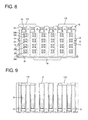
- One or more finger placing portions 17A projecting outward (e.g. upward) are formed at the (preferably substantially opposite) lateral (left and/or right) end(s) of the rear edge (or near thereto) of the lateral (upper) wall of the female frame 15 in FIG. 8.
- at least one finger placing portion 17B projecting outward (e.g. downward) is formed at an intermediate position (preferably near the transverse center) of the rear edge of the lateral (bottom) wall of the female frame 15 in FIG. 8.
- An operator can easily separate the female frame 15 from the male housing 12 by holding the one or more finger placing portions 17A, 17B preferably by the fingers.
- One or more interlocking portions 18 projecting transversely outward are formed at intermediate positions (preferably near the vertical centers) of the (preferably substantially opposite) lateral (left and/or right) wall(s) of the female frame 15 in FIG. 8 and are engageable with one or more respective lock portions 19 of the male housing 12 to be described later.
- the front surface of each interlocking portion 18 preferably is formed into an inclined surface 20A for facilitating a movement of the lock portion 19 onto the interlocking portion 18, and the rear surface thereof is formed into a locking surface 21 A preferably inclined slightly backward toward its projecting end.
- At least one guiding groove 22 extending substantially in forward and backward directions FBD is formed at an intermediate position (preferably near a vertical middle position) of each interlocking portion 18.
- These one or more guiding grooves 22 are engaged or engageable with forcible collision preventing ribs 23 of the male housing 12 to be described later, whereby the entrance of the female frame 15 in an improper orientation (such as in a vertically inclined posture) can be prevented upon at least partly accommodating the female frame 15 into the male housing 12. This can prevent the front end of the female frame 15 from forcibly colliding with the male tabs 10.
- one or more, preferably a plurality of (six in the shown example) accommodating chambers 24 into which the auxiliary connectors 14 are to be at least partly accommodated from an insertion side (preferably substantially from behind) are so formed preferably substantially side by side along width direction WD (transverse direction in FIG. 10) in the female frame 15 as to substantially make openings in the rear wall of the female frame 15.
- the respective accommodating chambers 24 preferably are shaped to substantially be narrow and long in vertical direction (or a direction at an angle different from 0° or 180°, preferably substantially normal to the width direction WD, e.g. vertical direction in FIG. 10), and the adjacent accommodating chambers 24 are at least partly partitioned by one or more partition walls 25.
- One or more, preferably a plurality of (three in the shown example) ribs 26 are so formed on the lateral (left) wall of each accommodating chamber 24 in FIG. 10 as to project inward, to extend substantially forward from the rear edge of the female frame 15, and to be preferably arranged one above another and are designed to guide the entrance of the one or more auxiliary connectors 14 into the accommodating chambers 24 by being engaged with one or more respective guiding grooves 27 formed in the auxiliary connectors 14.
- One or more, preferably a plurality of (four in the shown example) male tab insertion holes 28A through which the one or more male tabs 10 are at least partly inserted are formed preferably one above another in the front wall of each accommodating chamber 24, and a slanted surface 29A for guiding the insertion of the male tab 10 is formed at the opening edge of each male tab insertion hole 28A as shown in FIG. 8.
- a (preferably substantially cantilever-shaped) frame side locking portion 30 is formed in the lateral (ceiling) wall of the (preferably each) accommodating chamber 24 to project substantially forward.
- Parts of the female frame 15 before the frame side locking portions 30 preferably are cut off, so that a disengagement jig (not shown) for forcibly resiliently deforming the frame side locking portions 30 in unlocking direction UD (in a direction at an angle different from 0° or 180°, preferably substantially normal to the connecting direction CD) is at least partly insertable upon separating the female frame 15 from the male housing 12.
- Each frame side locking portion 30 is formed such that the front end thereof is a free end, and comprised of at least one resiliently deformable arm portion 31 and at least one locking projection 32 at least partly projecting into the accommodating chamber 24 substantially at a position of the lower surface of the arm portion 31 (e.g. slightly retracted from the front end).
- the locking projection 32 is designed to retain the auxiliary connector 14 by being engaged with a partial locking or first interacting portion 33 of the auxiliary connector 14 to be described later with the auxiliary connector 14 inserted to a substantially proper position in the accommodating chamber 24.
- the rear surface of the locking projection 32 preferably is formed into an inclined surface 20B so that the locking projection 32 can easily move onto the partial locking or first interacting portion 33 of the auxiliary connector 14, whereas the front surface thereof is formed into a locking surface 21 B preferably slightly inclined forward toward the back.
- a disengagement recess 34 into which the leading end of the disengagement jig (not shown) for forcibly resiliently deforming the frame side locking portion 30 is fittable or insertable is formed in the front end surface of the arm portion 31.
- the front end surface of the arm portion 31 is inclined outward or upward toward the front, so that a portion defined between the upper surface and the front end surface of the arm portion 31 has a pointed configuration.
- Each auxiliary connector 14 is made e.g. of a synthetic resin and preferably has such a flat shape as to have a small dimension in width direction WD (transverse direction in FIG. 11) as shown in FIGS. 11 to 14.
- the partial locking or first interacting portion 33 projecting outward or upward is formed at or near the front end (right end in FIG. 13) of the upper wall of the auxiliary connector 14.
- the front surface of the partial locking or first interacting portion 33 is formed into an inclined surface 20C so that the locking projection 32 of the frame side locking portion 30 can easily move onto the partial locking or first interacting portion 33, whereas the rear surface thereof is formed into a locking surface 21C preferably slightly inclined backward toward the top.
- the inclined surface 20C of the partial locking or first interacting portion 33 of the auxiliary connector 14 comes substantially into sliding contact with the inclined surface 20B of the locking projection 32 of the frame side locking portion 30 (from behind) during the insertion and, accordingly, the frame side locking portion 30 is resiliently deformed in the unlocking direction UD or upward or outward.
- the locking projection 32 of the frame side locking portion 30 moves over the partial locking or first interacting portion 33 of the auxiliary connector 14 to resiliently at least partly restore the frame side locking portion 30, whereby the locking surface 21 B of the locking projection 32 of the frame side locking portion 30 comes into contact with the locking surface 21C of the partial locking or first interacting portion 33 of the auxiliary connector 14 from behind. In this way, the auxiliary connector 14 is prevented from coming out backward (see FIG. 1).
- one or more, preferably a plurality of (four in the shown example) cavities 35 for at least partly accommodating the female terminal fittings 13 are formed preferably one above another (in vertical direction in FIG. 14) in each auxiliary connector 14 and extend substantially in forward and backward directions FBD (transverse direction in FIG. 14).
- the female terminal fittings 13 mounted on or connected to ends of wires 36 are at least partly accommodated in the cavities 35.
- Each female terminal fitting 13 includes a wire connection portion (preferably comprising a barrel portion 37) to be connected (preferably crimped or bent or folded into connection) with the wire 36, and a connecting tube portion 38 formed before the wire connecting portion (preferably the barrel portion 37) and designed to establish an electrical connection with the busbar 11 by the at least partial insertion of the male tab 10 thereinto.
- a locking hole 41 engageable with an auxiliary-connector side locking portion 40 to be described later is formed in the lateral (bottom) wall of the connecting tube portion 38.
- a male tab insertion hole 28B through which the male tab 10 is at least partly inserted is formed in the front wall of each cavity 35, and a tapered or inclined surface 29B for guiding the insertion of the male tab 10 is formed at the opening edge of each male tab insertion hole 28B.
- the (preferably substantially cantilever-shaped) auxiliary-connector side locking portion 40 extending substantially forward and resiliently engageable with the female terminal fitting 13 is formed at the lateral (bottom) wall of preferably each cavity 35.
- This auxiliary-connector side locking portion 40 is resiliently engaged with the locking hole 41 of the aforementioned female terminal fitting 13 to prevent the female terminal fitting 13 from coming out backward.
- a retainer 39 for retaining the properly inserted female terminal fittings 13 preferably in cooperation with the auxiliary-connector side locking portions 40 is formed at a lateral (left) wall 42 of each auxiliary connector 14 in FIGS. 11 and 12.
- the retainer 39 projects substantially forward (rightward in FIG. 13) from the lateral (left) wall 42 of the auxiliary connector 14 preferably while being supported at one end, and is pivotal or rotatable about the base end thereof.
- a retainer accommodating hole (not shown) for at least partly accommodating the retainer 39 is formed in the lateral (left) wall 42 of the auxiliary connector 14.
- the retainer 39 can be held retained or positioned at least partly in the retainer accommodating hole preferably by the engagement of the front edge of the retainer 39 and the edge of the retainer accommodating hole.
- the retainer 39 While being held or positioned in the retainer accommodating hole, the retainer 39 is engaged with the rear edges of the connecting tube portions 38 of the female terminal fittings 13 from an inserting side, preferably substantially from behind, thereby preferably doubly locking the female terminal fittings 13 in cooperation with the auxiliary-connector side locking portions 40 (see FIG. 14).
- one or more, preferably a plurality of (three in the shown example) guiding grooves 27 extending substantially in forward and backward directions FBD are formed one above another in the lateral (right) wall of the (preferably each) auxiliary connector 14 in FIGS. 11 and 12, and are engageable with the aforementioned one or more ribs 26 of the female frame 15.
- the bracket 16 preferably is in the form of a rigid (preferably metal) plate and is to be provided on an unillustrated fixing body used to mount the connector.
- At least one locking section 44 is formed to penetrate or recess the bracket 16 in thickness direction TD, and can inseparably hold the male housing 12 and the bracket 16 by the engagement with at least one engaging portion 45 of the male housing 12 to be described later.
- the male housing 12 is made e.g. of a synthetic resin and includes a receptacle 46 having an open front side and at least one busbar holding portion 47 provided near or behind the receptacle 46 as shown in FIG. 1.
- a receptacle 46 having an open front side and at least one busbar holding portion 47 provided near or behind the receptacle 46 as shown in FIG. 1.
- one or more, preferably a plurality of (e.g. four in the shown example) busbar holding grooves 48 for holding the busbars 11 are formed preferably one substantially above another in a wall surface (back surface of the receptacle 46) of the busbar holding portion exposed to the receptacle 46 and extend in width direction WD (transverse direction in FIG. 16).
- each busbar 11 preferably is formed by punching or cutting or stamping a conductive (preferably metallic) plate material out into a specified (predetermined or predeterminable) shape and includes one or more, preferably a plurality of male tabs 10, at least one coupling portion 49 coupling these male tabs 10, and one or more fixing portions 50 projecting from a side of the coupling portion 49 preferably substantially opposite or corresponding to the male tabs 10.
- Each busbar 11 is held in the corresponding busbar holding groove 48 by having the coupling portion 49 at least partly accommodated in the busbar holding groove 48 and having the one or more fixing portions 50 pressed into one or more respective fixing holes 51 formed in the busbar holding groove 48. With the busbar 11 fixed in the busbar holding groove 48, the male tabs 10 at least partly project into the receptacle 46.
- the lateral (left and/or right) end(s) (upper and/or lower ends in FIG. 18) of the front edge (right end portion in FIG. 18) of the ceiling wall of the receptacle 46 are recessed backward (leftward in FIG. 18) to form one or more notches 52.
- a dimension of the notches 52 substantially in forward and backward directions FBD preferably is set to be substantially equal to the thickness of the aforementioned finger placing portions 17A of the female frame 15 (see FIG. 2).
- one or more finger placing slants 53A sloped outward or up toward the back are formed in the outer surface of the lateral (ceiling) wall of the receptacle 46 to substantially extend from the notches 52.
- the front edge of the lateral or bottom wall of the receptacle 46 in FIG. 16 is recessed backward (leftward in FIG. 18) in an intermediate position (preferably substantially in the transverse center in FIG. 16) to form at least one notch 52.
- a dimension of this notch 52 in forward and backward directions FBD preferably is set to be substantially equal to the thickness of the aforementioned finger placing portion 17B of the female frame 15.
- a finger placing slant 53B sloped outward or down toward the back is formed in the outer surface of the lateral (bottom) wall of the receptacle 46 preferably to extend from this notch 52.
- the rear end surface of the female frame 15 and the front end surface of the male housing 12 preferably are set to be substantially flush with each other with the female frame 15 and the male housing 12 properly connected.
- the outer or upper ends of the finger placing portions 17A of the female frame 15 and/or the outer or bottom end of the finger placing portion 17B preferably are set to be respectively substantially flush with the respective lateral (upper and/or bottom) surface(s) of the male housing 12 with the female frame 15 and the male housing 12 properly connected.
- one or more, preferably a plurality of (e.g. six in this embodiment) partial connection or first detecting ribs 54 project inwardly or down from the inner surface of the lateral (ceiling) wall of the receptacle 46 and extend substantially forward from the rear end of this ceiling wall (or a position close thereto) towards or to a position retracted slightly backward from the front edge of the ceiling wall.
- the front ends of the partial connection detecting ribs 54 are formed to have a downward or inward inclination toward the front, thereby having a pointed or converging configuration. As shown in FIG.
- the frame side locking portion 30 of the female frame 15 remains resiliently deformed upward or outward without being resiliently restored if the auxiliary connector 14 is left insufficiently fitted into the female frame 15. If an attempt is made to fit the female frame 15 into the male housing 12 in this state, the front edge of the frame side locking portion 30 comes substantially into contact with (preferably the front edge of) the partial connection detecting rib 54 formed to project downward or inward from the ceiling wall of the receptacle 46 from front, thereby hindering any further insertion of the auxiliary connector 14. In this way, the partial connection of the auxiliary connector 14 can be detected. Further, the ceiling wall of the receptacle 46 can be reinforced by these partial connection detecting ribs 54.
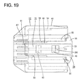
- the front edge of a lateral (left) wall 58 of the receptacle 46 in FIG. 16 is formed to bulge out slightly forward (rightward in FIG. 19) as shown in FIG. 19 and preferably serves as a bracket guiding portion 56 for guiding the bracket 16 to one or more guide rails 55 to be described later.
- the one or more forcible collision preventing ribs 23 extending substantially in forward and backward directions FBD are formed in intermediate positions (preferably substantially in the vertical centers) of the inner surface(s) of lateral (right and/or left) wall(s) 57, 58 of the receptacle 46 in FIG. 16.
- These forcible collision preventing ribs 23 are at least partly fitted into the guiding grooves 22 formed in the female frame 15, thereby preventing the female frame 15 from entering the receptacle 46 in an improper orientation (e.g. in a vertically inclined state) to bring the front end of the female frame 15 into contact with the male tabs 10, and the front edges of the forcible collision preventing ribs 23 are so inclined as to be easily fittable into the guiding grooves 22.
- the one formed on the lateral (right) wall 57 in FIG. 16 extends substantially backward from the front edge of the right wall 57, i.e. from a connecting surface with the female frame 15, whereas the one formed on the substantially opposite lateral (left) wall 58 extends backward from a position slightly retracted backward (rightward in FIG. 22) from the front edge of the lateral (left) wall 58 and/or preferably is substantially aligned with the front end position of the forcible collision preventing rib 23 of the right wall 57 as shown in FIG. 22.
- This can prevent the female frame 15 from being fitted into the receptacle 46 in an improper orientation, e.g. in such an inclined posture with respect to width direction WD that either one of the lateral (left and right) sides of the front end of the female frame 15 precedes the other, thereby preventing the front end of the female frame 15 from coming into contact with the male tabs 10.
- one or more, preferably two slits 59 are formed in an intermediate position (preferably substantially in the vertical center) of the outer surface of (preferably each of) the lateral (right and/or left) wall(s) 57, 58 of the receptacle 46 preferably while being vertically spaced apart by a specified (predetermined or predeterminable) distance.
- These slits extend substantially forward from the rear edge of each of the right and left walls 57, 58 up to an intermediate position (preferably a substantial center position) with respect to forward and backward directions FBD.
- an area between the two upper and lower slits 59 is resiliently deformable outward in the thickness direction of each of the lateral (right and left) walls 57, 58 and serves as a lock portion 19 engageable with the corresponding interlocking portion 18 of the female frame 15 to retain the female frame 15.
- the lock portion 19 formed in the lateral (right) wall 57 extends backward (rightward in FIG. 20) from a base end 60 toward a free end 61.
- the lock portion 19 formed in the substantially opposite lateral (left) wall 58 extends backward (leftward in FIG. 19) from a base end 60 toward a free end 61 along an inserting direction ID of the bracket 16 to be described later into a clearance defined between the guide rails 55.
- a lock projection 63 is formed to project inward from the inner surface of each lock portion 19.
- the front surface (right surface in FIG. 5) of the lock projection 63 preferably is formed into an inclined surface 20D so that the lock projection 63 can easily move onto the interlocking portion 18 of the female frame 15.
- the rear surface (left surface in FIG. 5) of the lock projection 63 is formed into a locking surface 21 D preferably slightly inclined backward toward its projecting end.
- the inclined surface(s) 20A of the interlocking portion(s) 18 of the female frame 15 come(s) into sliding contact with the inclined surface(s) 20D of the lock projection(s) 63 of the lock portion(s) 19 of the male housing 12 during this fitting operation and, accordingly, the lock portion(s) 19 is/are resiliently deformed into the deformation area(s) 62.
- the lock projection(s) 63 of the lock portion(s) 19 move(s) over the interlocking portion(s) 18 of the female frame 15 to resiliently at least partly restore the lock portion(s) 19, whereby the locking surface(s) 21 D of the lock projection(s) 63 come(s) into contact with the locking surface(s) 21A of the interlocking portion(s) 18 of the female frame 15 to retain the female frame 15.
- the aforementioned one or more forcible collision preventing ribs 23 extend on the inner surfaces of the lock portion(s) 19 and serve to reinforce the lock portion(s) 19.
- the forcible collision preventing ribs 23 preferably cross the lock projections 63 in forward and backward directions FBD at intermediate positions (preferably at substantially vertical middle positions).
- one or more, preferably a pair of guide rails 55 which extend substantially in forward and backward directions FBD adjacent (above and/or below) the lock portion 19 and preferably between which the bracket 16 is insertable are formed on the outer surface of the lateral (left) wall 58 of the receptacle 46 to project outward in the thickness direction of the lateral (left) wall 58.
- These guide rails 55 extend substantially backward from positions near the front end of the lateral (left) wall 58 substantially up to positions slightly before the rear edge of the lock portion 19. As shown in FIG.
- the guide rails 55 preferably have a substantially L-shaped cross section when viewed from front, and the bracket 16 is at least partly inserted in the inserting direction ID into an area defined between the outer surface of the left wall 58 and surfaces of the guide rails 55 facing the left wall 58.
- the bracket 16 is stopped at its front end position in the inserting direction ID preferably by the contact of the leading end of the bracket 16 with the back walls of the guide rails 55 (see FIG. 6).
- the engaging portion 45 for fixing the bracket 16 and the male housing 12 to each other by being engaged with the locking section 44 of the bracket 16 preferably is so formed in an area of the outer surface of the lateral (left) wall 58 of the receptacle 46 between the pair of upper and lower guide rails 55 before (at the right side in FIG. 19) the lock portion 19 as to project outward laterally or outwardly or in the thickness direction of the left wall 58 (see FIG. 16).
- the front surface right surface in FIG.
- the engaging portion 45 preferably is formed into an inclined surface 20E so that the bracket 16 can easily move thereonto, whereas the rear surface of the engaging portion 45 is formed into a locking surface 21 E preferably substantially upright with respect to the outer surface of the lateral (left) wall 42.
- the bracket 16 is retained by the contact of the locking surface 21 E of the engaging portion 45 with the opening edge of the locking section 44 of the bracket 16 from front.
- the height of the guide rails 55 from the outer surface of the lateral (left) wall 58 preferably is set to be larger than those of the lock portion 19 and the engaging portion 45 from the outer surface of the left wall 58.
- the lock portion 19 and the engaging portion 45 are protected by the guide rails 55, thereby being prevented from collision with external matters.
- the length of the bracket 16 in forward and backward directions FBD preferably is set such that the bracket 16 is at least partly located in the deformation area 62 of the lock portion 19 with the bracket 16 at least partly inserted between the guide rails 55 and the locking section 44 of the bracket 16 engaged with the engaging portion 45 of the male housing 12.
- the female frame 15 preferably is doubly locked by the lock portion 19 and the bracket 16.
- the one or more busbars 11 are pressed or inserted or fitted into the one or more respective busbar holding grooves 48 of the male housing 12 preferably substantially from front. Then, the one or more fixing portions 50 of the busbars 11 are pressed or fitted into the fixing holes 51 of the busbar holding grooves 48, whereby the busbars 11 are fixed in the busbar holding grooves 48 and the one or more male tabs 10 thereof at least partly project into the receptacle 46.
- the female terminal fittings 13 mounted at the ends of the wires 36 are at least partly inserted into the respective cavities 35 of the auxiliary connectors 14 preferably substantially from behind. Then, the female terminal fittings 13 are retained by the auxiliary-connector side locking portions 40. Thereafter, the retainer 39 preferably is at least partly accommodated into the retainer accommodating hole to preferably doubly lock the female terminal fittings 13.
- the auxiliary connector 14 having the one or more female terminal fittings 13 at least partly accommodated therein is at least partly inserted into each accommodating chamber 24 of the female frame 15 from the inserting side, preferably substantially from behind.
- the inclined surface 20C of the partial locking or first interacting portion 33 of the auxiliary connector 14 comes substantially into sliding contact with the inclined surface 20B of the locking projection 32 of the frame side locking portion 30 (preferably substantially from behind) during this inserting operation and, accordingly, the frame side locking portion 30 is resiliently deformed outward or upward.
- the locking projection 32 of the frame side locking portion 30 moves over the partial locking or first interacting portion 33 of the auxiliary connector 14 to resiliently at least partly restore the frame side locking portion 30, and the locking surface 21 B of the locking projection 32 of the frame side locking portion 30 comes substantially into contact with the locking surface 21C of the partial locking interacting portion 33 of the auxiliary connector 14 (preferably substantially from behind) to prevent the auxiliary connector 14 from coming out backward.
- the auxiliary connector 14 at least partly accommodated in the accommodating chamber 24 of the female frame 15, the rear end of the auxiliary connector 14 is exposed through the rear surface of the female frame 15 so that the wires 36 can be drawn out through the rear surface of the auxiliary connector 14 (see FIG. 15).
- the female frame 15 having the one or more auxiliary connectors 14 at least partly accommodated therein is fitted or inserted into the receptacle 46 of the male housing 12.
- the one or more forcible collision preventing ribs 23 formed in or at the receptacle 46 of the male housing 12 and the one or more guiding grooves 22 formed in the female frame 15 are engaged, and the female frame 15 is at least partly inserted into the receptacle 46. This can prevent the female frame 15 from being inserted in an improper posture such as in a vertically inclined state into the receptacle 46.
- the one or more forcible collision preventing ribs 23 preferably extend backward from substantially transversely symmetrical positions of the lateral (right and left) walls 57, 58 of the receptacle 46, which can prevent the female frame 15 from being inserted into the receptacle 46 in an improper posture such as in such a posture inclined with respect to width direction that either one of the left and right sides of the front end of the female frame 15 precedes the other. In this way, there can be prevented the collision of the front end of the female frame 15 with the male tabs 10 projecting in the receptacle 46, i.e. so-called "forcible collision" resulting from the insertion of the female frame 15 into the receptacle 46 in an improper or inclined posture.
- the inclined surfaces 20A of the interlocking portions 18 of the female frame 15 come into (preferably substantially sliding) contact with the inclined surfaces 20D of the lock projections 63 of the male housing 12 from front and, accordingly, the lock portion(s) 19 is/are resiliently deformed at least partly into the deformation area(s) 62.
- the lock projection(s) 63 of the lock portion(s) 19 move(s) over the interlocking portion(s) 18 of the female frame 15 to resiliently at least partly restore the lock portion(s) 19 and the locking surface(s) 21 D of the lock projection(s) 63 come(s) into contact with the locking surface(s) 21A of the interlocking portion(s) 18 of the female frame 15, thereby retaining the female frame 15.
- the one or more male tabs 10 of the male housing 12 are at least partly inserted in the connecting tube portions 38 of the female terminal fittings 13 through the one or more respective male tab insertion holes 28A of the female frame 15 and the one or more respective male tab insertion holes 28B of the auxiliary connector(s) 14, whereby the male tabs 10 are electrically connected with the female terminal fittings 13.
- specified (predetermined or predeterminable) female terminal fittings 13 are shorted by the busbars 11.
- the frame side locking portion 30 of the female frame 15 remains resiliently deformed outward or upward without being able to be (sufficiently) resiliently restored. If an attempt is made to connect the female frame 15 with the male housing 12 in this state, the front end of the frame side locking portion 30 comes substantially into contact with the front end of the at least one partial connection detecting rib 54 from front to hinder the insertion of the auxiliary connector 14. In this way, the partial connection of the auxiliary connector 14 can be detected or avoided.
- the front end of the frame side locking portion 30 preferably has a specific pointed or converging configuration (e.g.
- the front end of the partial connection detecting rib 54 has a pointed or converging configuration inclined in a substantially complementary manner (backward toward the top) to the specific pointed or converging configuration of the partial connection detecting rib 54.
- the bracket 16 is at least partly inserted into between the guide rails 55 of the male housing 12.
- the outer surface of the bracket guiding portion 56 of the male housing 12 is brought into contact with (preferably the leading end of) the bracket 16. This makes it easier to guide the bracket 16 into the clearance between the guide rails 55.
- the male housing 12 is pushed forward (rightward in FIG. 6) with the bracket 16 held substantially in contact with the bracket guiding portion 56, the leading end of the bracket 16 comes substantially into contact with the inclined surface 20E of the engaging portion 45 of the male housing 12 preferably substantially from front. Then, the bracket 16 moves onto the engaging portion 45 to be resiliently deformed.
- the bracket 16 moves over the engaging portion 45 to be resiliently at least partly restored, whereby the engaging portion 45 of the male housing 12 is at least partly fitted into the locking section 44 of the bracket 16 to bring the locking surface 21 E of the engaging portion 45 into contact with the opening edge of the locking section 44 of the bracket 16 preferably substantially from front. In this way, the bracket 16 is locked. In this state, the leading end of the bracket 16 at least partly enters the area (deformation area 62) outside the lock portion 19 of the male housing 12 in the thickness direction of the lateral (left) wall 58, thereby preventing the lock portion 19 from being resiliently deformed into the deformation area 62.
- the lock portion 19 can be prevented from undergoing such a resilient deformation as to disengage the lock projection 63 thereof from the interlocking portion 18 of the female frame 15. Therefore, the male housing 12 and the female frame 15 can be locked into each other with an increased force.
- the lock portions 19 extend substantially backward (leftward in FIG. 6) from the base ends 60 toward the free ends 61, and this extending direction is along the inserting direction ID (leftward in FIG. 6) of the bracket 16 into the clearance between the guide rails 55. Since the bracket 16 is at least partly inserted in the inserting direction ID into between the guide rails 55 from the base end side of the lock portion 19, the resilient deformation of the base end of the lock portion 19 can be more securely prevented. As a result, the male housing 12 and the female frame 15 can be locked into each other with an even increased force.
- the bracket 16 Upon disassembling the connector assembled as above, for example, for maintenance, the bracket 16 is resiliently deformed outward by an unillustrated jig to disengage the engaging portion 45 and the locking portion 44 and the male housing 12 is pulled backward, whereby the male housing 12 and the bracket 16 can be separated from each other.
- the lock portion(s) 19 is/are resiliently deformed into the deformation area(s) 62 by means of an unillustrated jig to disengage the lock portion(s) 19 and the interlocking portion(s) 18, and the male housing 12 and female frame 15 are pulled backward away from each other to be separated.
- the finger placing portions 17A, 17B since the one or more notches 52 are formed at the front edges of the ceiling wall and the bottom wall of the receptacle 46 of the male housing 12, the one or more finger placing portions 17A, 17B of the female frame 15 are at least partly accommodated in these notches 52, and the one or more finger placing slants 53A, 53B are formed on the outer or upper surface of the ceiling wall and/or on the outer or lower surface of the bottom wall.
- the unillustrated disengagement jig is or can be at least partly inserted into the accommodating chamber 24 through an area of the female frame 15 before the frame side locking portion 30 to bring the leading end thereof substantially into contact with the disengagement recess 34 of the frame side locking portion 30 from front.
- the frame side locking portion 30 is resiliently deformed outward or upward by this disengagement jig to disengage the locking projection 32 of the frame side locking portion 30 and the partial locking interacting portion 33 of the auxiliary connector 14, and the auxiliary connector 14 is or can be pulled backward to be separated from the female frame 15.
- the auxiliary-connector side locking portions 40 are pressed by an unillustrated jig to disengage the female terminal fittings 13, and the female terminal fittings 13 are pulled backward to separate the auxiliary connector 14 and the female terminal fittings 13.
- the resilient deformation of the lock portion 19 can be prevented by the bracket 16 having at least partly entered the deformation space for the lock arm 19.
- the lock portion 19 can be prevented from undergoing such a resilient deformation as to disengage the lock portion 19 and the interlocking portion 18, wherefore the male housing 12 and the female frame 15 can be locked into each other with an increased locking force.
- bracket 16 is at least partly inserted into between the guide rails 55 from the side of the base end 60 of the lock portion 19, the resilient deformation of the base end 60 of the lock portion 19 can be securely prevented. As a result, the male housing 12 and the female frame 15 can be locked into each other with an even increased locking force.
- the one or more guide rails 55 of the male housing 12 are formed at the preferably substantially opposite sides of the lock portion 19 and the engaging portion 45 and the height of at least part of the guide rails 55 from the lateral (left) wall 58 preferably is set to be larger than those of the lock portion 19 and the engaging portion 45 from the lateral (left) wall 58. This can suppress the collision of the lock portion 19 and the engaging portion 45 with external matters.
- the female frame 15 can be prevented from entering the receptacle 46 in an improper orientation (e.g. in a vertically inclined posture) by the engagement of the forcible collision preventing rib(s) 23 of the male housing 12 and the guiding grooves 22 of the female frame 15. This can prevent the male tabs 10 from being broken due to the forcible collision by the female frame 15.
- the one or more forcible collision preventing ribs 23 extend up to the inner surfaces of the lock portion(s) 19, the lock portion(s) 19 can be reinforced thereby.
- the forcible collision preventing ribs 23 double as reinforcing members for the lock portion(s) 19, the connector can be made smaller as compared to a case where ribs are separately provided to reinforce the lock portions 19.
- a lateral (left) wall 58 of a male housing 12 is formed with at least one lock portion 19 resiliently deformable outward in the thickness direction of the lateral (left) wall 58, and the male housing 12 and a female frame 15 are properly connected by the engagement of the lock portion 19 with an interlocking portion 18 formed in the female frame 15.
- a bracket 16 is to be at least partly inserted into a deformation area 62 for the lock portion 19. The resilient deformation of the lock portion 19 can be prevented by the entrance of the bracket 16 into the deformation area 62 for the lock portion 19.
- At least one excessive deformation preventing piece 64 for the lock portion 19 is formed to span or bridge between rear portions (preferably the rear ends) of the pair of guide rail 55 projecting from the male housing 12.
- This excessive deformation preventing piece 64 preferably is designed to at least partly cover the rear end of the lock portion 19 from the outside. Since the construction other than the above is similar or substantially the same as in the first embodiment, it is not described again by identifying the similar or same members by the same reference numerals.
- the lock portion 19 may be pushed outward by an excessive force by the outer wall of the female frame 15, thereby being excessively deformed. In such a case, the lock portion 19 may be plastically deformed to incompletely engage the lock portion 19 and the interlocking portion 18, whereby a connecting force of the female frame 15 and the male housing 12 may be reduced.
- the excessive deformation preventing piece 64 is formed to at least partly cover the lock portion 19 from the outer side in this embodiment.
- an excessive deformation of the lock portion 19 can be prevented by the contact of the excessive deformation preventing piece 64 with the lock portion 19 from the outer side. Therefore, a reduction in the connecting force of the female frame 15 and the male housing 12 can be prevented.
Abstract
Description
- The present invention relates to a connector.
- There has been known a connector including a pair of connector housings connectable one inside the other (see
Japanese Unexamined Patent Publication No. 2000-243502 - Since the lock portion is resiliently deformable outward in the thickness direction of the side wall in the connector having the above construction, when a strong force acts, for example, in such a direction as to separate the two connector housings, there is a possibility that the lock portion is resiliently deformed outward in the thickness direction of the side wall to be disengaged from the interlocking portion, thereby separating the two connector housings.
- The present invention was developed in view of the above problem and an object thereof is to provide a connector having an increased interlocking force of connector housings.
- This object is solved according to the invention by the features of claim 1. Preferred embodiments of the invention are subject of the dependent claims.
- According to the invention, there is provided a connector, comprising:
- at least one pair of connector housings connectable one at least partly inside the other,
- at least one lock portion provided at a side wall of the outer connector housing located at an outer side in a properly connected state of the connector housings and resiliently deformable substantially outward in the thickness direction of the side wall, and
- at least one interlocking portion formed at the inner connector housing and engageable with the lock portion to inseparably hold the two connector housings,
wherein:- at least one engaging portion engageable with at least one locking section formed at a bracket is provided at the side wall of the outer connector housing, and
- the bracket is at least partly inserted or fitted into a deformation area for the lock portion with the locking section of the bracket and the engaging portion of the outer connector housing engaged with each other.
- Accordingly, when the locking section of the bracket and the engaging portion of the outer connector housing are engaged with the outer and inner connector housings substantially properly connected, an outward resilient deformation of the lock portion in the thickness direction of the side wall of the outer connector housing can be prevented by the bracket at least partly inserted into the deformation area for the lock portion. As a result, even if a strong force acts in such a direction as to separate the two connector housings, the disengagement of the lock portion and the interlocking portion can be prevented, wherefore the two connector housings can be locked into each other with an increased force.
- According to a preferred embodiment of the invention, at least one pair of guide rails between which the bracket is at least partly insertable are so formed on the side wall of the outer connector housing preferably at the substantially opposite sides of the lock portion and/or the engaging portion as to extend substantially in an inserting direction of the bracket and to project substantially outward in the thickness direction of the side wall.
- Preferably, the height of the guide rails from the side wall is set to be larger than those of the lock portion and the engaging portion from the side wall.
- Accordingly, the guide rails of the outer connector housing are formed preferably at the substantially opposite sides of the lock portion and the engaging portion, and the height thereof from the side wall preferably is set to be larger than those of the lock portion and the engaging portion from the side wall. Thus, the collision of the lock portion and the engaging portion with external matters can be suppressed.
- Further preferably, the lock portion is substantially in the form of a cantilever formed between slits made in the side wall of the outer connector housing and/or extends along an inserting direction of the bracket from a base end thereof toward a free end thereof.
- Accordingly, an outward resilient deformation of the base end of the lock portion substantially in the thickness direction of the side wall of the outer connector housing can be securely prevented since the bracket is at least partly inserted into between the guide rails from the side of the base end of the lock portion. As a result, the two connector housings can be more securely locked into each other.
- Further preferably, at least one lock-portion excessive deformation preventing piece for preventing an excessive deformation of the lock portion is provided on the side wall.
- Still further preferably, the lock-portion excessive deformation preventing piece at least partly covers the lock portion and/or is formed to span between the pair of guide rails.
- Most preferably, at least one lock-portion excessive deformation preventing piece for covering the lock portion is formed to span between the pair of guide rails.
- If the inner connector housing is, for example, fitted in an oblique posture, there is a possibility that the lock portion is pressed outward by an excessive force given from an outer wall of the inner connector housing and may be excessively deformed. In such a case, the lock portion may be plastically deformed to incompletely engage the lock portion and the interlocking portion, whereby the locking force of the two connector housings may be reduced.
- According to the above preferred embodiment, since the excessive deformation preventing piece is formed to at least partly cover the lock portion, an excessive deformation of the lock portion can be prevented by the contact of the excessive deformation preventing piece from the outer side even if the lock portion is pressed outward by an excessive force. This can prevent a reduction in the locking force of the two connector housings.
- According to a further preferred embodiment of the invention, at least one forcible collision preventing rib:
- is so formed on the inner surface of the side wall of the outer connector housing as to project inward in the thickness direction of the side wall and to extend substantially forward from a connection surface of the outer connector housing with the inner connector housing along a connecting direction with the inner connector housing,
- is engageable with at least one guiding groove formed in an outer surface of a side wall of the inner connector housing, and/or
- extends substantially up to the inner surface of the lock portion.
- Accordingly, a so-called "forcible collision" resulting from an oblique posture of the inner connector housing being fitted can be prevented during the connecting operation of the two connector housings by the engagement of the forcible collision preventing rib formed in the outer connector housing and the guide groove formed in the inner connector housing.
- Further, since the forcible collision preventing rib extends up to the inner surface of the lock portion, the lock portion can be reinforced by this forcible collision preventing rib. In addition, since the forcible collision preventing rib doubles as a reinforcing member for the lock portion, the connector can be made smaller as compared to a case where a rib for reinforcing the lock portion is separately provided.
- Preferably, the inner connector housing comprises a frame into which one or more auxiliary connectors are at least partly insertable.
- Further preferably, there are provided one or more partial connection detection portions for detecting or avoiding a partial connection of at least part of the auxiliary connectors and the inner connector housing.
- Most preferably, the outer connector housing comprises on or more notches into which one or more finger placing portions for allowing an operation of the outer connector housing can be at least partly accommodated.
- These and other objects, features and advantages of the present invention will become more apparent upon reading of the following detailed description of preferred embodiments and accompanying drawings. It should be understood that even though embodiments are separately described, single features thereof may be combined to additional embodiments.
- FIG. 1 is a vertical section of a connector according to a first embodiment of the invention,
- FIG. 2 is a plan view of the connector,
- FIG. 3 is a bottom view of the connector,
- FIG. 4 is a rear view of the connector without wires and female terminal fittings,
- FIG. 5 is a bottom view partly in section of the connector,
- FIG. 6 is a bottom view partly in section showing a state where a bracket is assembled into the connector,
- FIG. 7 is a side view of a female frame,
- FIG. 8 is a front view of the female frame,
- FIG. 9 is a plan view of the female frame,
- FIG. 10 is a rear view of the female frame,
- FIG. 11 is a front view of an auxiliary connector showing a state where a retainer is not accommodated in a retainer accommodating hole,
- FIG. 12 is a front view of the auxiliary connector showing a state where the retainer is accommodated in the retainer accommodating hole,
- FIG. 13 is a side view showing a side surface of the auxiliary connector where the retainer is formed,
- FIG. 14 is a side view partly in section showing a surface of the auxiliary connector opposite to the one where the retainer is formed with female terminal fittings inserted in the auxiliary connector,
- FIG. 15 is a plan view showing a state where the auxiliary connectors are inserted in the female frame,
- FIG. 16 is a front view of the a male housing,
- FIG. 17 is a rear view of the male housing,
- FIG. 18 is a plan view of the male housing,
- FIG. 19 is a left side view of the male housing,
- FIG. 20 is a right side view of the male housing,
- FIG. 21 is a bottom view partly in section of the male housing showing a lock portion and partial connection detecting ribs,
- FIG. 22 is a section along A-A of FIG. 16,
- FIG. 23 is a side view in section showing a partly connected state of the auxiliary connector where the partial connection detecting rib is in contact with a frame side locking portion, and
- FIG. 24 is a left side view of a male housing in a connector according to a second embodiment of the invention.
- A first preferred embodiment of the present invention is described with reference to FIGS. 1 to 23. A connector according to this embodiment is provided with at least one male housing 12 (corresponding to a preferred outer connector housing) at least partly accommodating one or
more busbars 11 having one or moremale tabs 10, and at least one female frame 15 (corresponding to a preferred inner connector housing) which is connectable with themale housing 12 and into which one or more, preferably a plurality ofauxiliary connectors 14 at least partly accommodating one or more femaleterminal fittings 13 are at least partly accommodated. With themale housing 12 and thefemale frame 15 properly connected, themale housing 12 is located substantially outside thefemale frame 15. Themale housing 12 is mounted or mountable on or to an unillustrated fixed body via abracket 16 provided on this fixed body. In the following description, directions of connecting CD themale housing 12 and thefemale frame 15 are referred to as forward directions and reference is made to FIG. 1 concerning vertical direction. - The
female frame 15 is made e.g. of a synthetic resin and substantially in the form of a block. One or morefinger placing portions 17A projecting outward (e.g. upward) are formed at the (preferably substantially opposite) lateral (left and/or right) end(s) of the rear edge (or near thereto) of the lateral (upper) wall of thefemale frame 15 in FIG. 8. Further, at least onefinger placing portion 17B projecting outward (e.g. downward) is formed at an intermediate position (preferably near the transverse center) of the rear edge of the lateral (bottom) wall of thefemale frame 15 in FIG. 8. An operator can easily separate thefemale frame 15 from themale housing 12 by holding the one or morefinger placing portions - One or more interlocking
portions 18 projecting transversely outward are formed at intermediate positions (preferably near the vertical centers) of the (preferably substantially opposite) lateral (left and/or right) wall(s) of thefemale frame 15 in FIG. 8 and are engageable with one or morerespective lock portions 19 of themale housing 12 to be described later. As shown in FIG. 5, the front surface of each interlockingportion 18 preferably is formed into aninclined surface 20A for facilitating a movement of thelock portion 19 onto the interlockingportion 18, and the rear surface thereof is formed into a lockingsurface 21 A preferably inclined slightly backward toward its projecting end. As shown in FIG. 7, at least one guidinggroove 22 extending substantially in forward and backward directions FBD is formed at an intermediate position (preferably near a vertical middle position) of each interlockingportion 18. These one or more guidinggrooves 22 are engaged or engageable with forciblecollision preventing ribs 23 of themale housing 12 to be described later, whereby the entrance of thefemale frame 15 in an improper orientation (such as in a vertically inclined posture) can be prevented upon at least partly accommodating thefemale frame 15 into themale housing 12. This can prevent the front end of thefemale frame 15 from forcibly colliding with themale tabs 10. - As shown in FIG. 10, one or more, preferably a plurality of (six in the shown example)
accommodating chambers 24 into which theauxiliary connectors 14 are to be at least partly accommodated from an insertion side (preferably substantially from behind) are so formed preferably substantially side by side along width direction WD (transverse direction in FIG. 10) in thefemale frame 15 as to substantially make openings in the rear wall of thefemale frame 15. The respectiveaccommodating chambers 24 preferably are shaped to substantially be narrow and long in vertical direction (or a direction at an angle different from 0° or 180°, preferably substantially normal to the width direction WD, e.g. vertical direction in FIG. 10), and the adjacentaccommodating chambers 24 are at least partly partitioned by one ormore partition walls 25. One or more, preferably a plurality of (three in the shown example)ribs 26 are so formed on the lateral (left) wall of eachaccommodating chamber 24 in FIG. 10 as to project inward, to extend substantially forward from the rear edge of thefemale frame 15, and to be preferably arranged one above another and are designed to guide the entrance of the one or moreauxiliary connectors 14 into theaccommodating chambers 24 by being engaged with one or more respective guidinggrooves 27 formed in theauxiliary connectors 14. One or more, preferably a plurality of (four in the shown example) maletab insertion holes 28A through which the one or moremale tabs 10 are at least partly inserted are formed preferably one above another in the front wall of eachaccommodating chamber 24, and aslanted surface 29A for guiding the insertion of themale tab 10 is formed at the opening edge of each maletab insertion hole 28A as shown in FIG. 8. - As shown in FIG. 1, a (preferably substantially cantilever-shaped) frame
side locking portion 30 is formed in the lateral (ceiling) wall of the (preferably each) accommodatingchamber 24 to project substantially forward. Parts of thefemale frame 15 before the frameside locking portions 30 preferably are cut off, so that a disengagement jig (not shown) for forcibly resiliently deforming the frameside locking portions 30 in unlocking direction UD (in a direction at an angle different from 0° or 180°, preferably substantially normal to the connecting direction CD) is at least partly insertable upon separating thefemale frame 15 from themale housing 12. - Each frame
side locking portion 30 is formed such that the front end thereof is a free end, and comprised of at least one resilientlydeformable arm portion 31 and at least one lockingprojection 32 at least partly projecting into theaccommodating chamber 24 substantially at a position of the lower surface of the arm portion 31 (e.g. slightly retracted from the front end). The lockingprojection 32 is designed to retain theauxiliary connector 14 by being engaged with a partial locking or first interactingportion 33 of theauxiliary connector 14 to be described later with theauxiliary connector 14 inserted to a substantially proper position in theaccommodating chamber 24. The rear surface of the lockingprojection 32 preferably is formed into aninclined surface 20B so that the lockingprojection 32 can easily move onto the partial locking or first interactingportion 33 of theauxiliary connector 14, whereas the front surface thereof is formed into a lockingsurface 21 B preferably slightly inclined forward toward the back. Adisengagement recess 34 into which the leading end of the disengagement jig (not shown) for forcibly resiliently deforming the frameside locking portion 30 is fittable or insertable is formed in the front end surface of thearm portion 31. The front end surface of thearm portion 31 is inclined outward or upward toward the front, so that a portion defined between the upper surface and the front end surface of thearm portion 31 has a pointed configuration. - Each
auxiliary connector 14 is made e.g. of a synthetic resin and preferably has such a flat shape as to have a small dimension in width direction WD (transverse direction in FIG. 11) as shown in FIGS. 11 to 14. The partial locking or first interactingportion 33 projecting outward or upward is formed at or near the front end (right end in FIG. 13) of the upper wall of theauxiliary connector 14. The front surface of the partial locking or first interactingportion 33 is formed into aninclined surface 20C so that the lockingprojection 32 of the frameside locking portion 30 can easily move onto the partial locking or first interactingportion 33, whereas the rear surface thereof is formed into a lockingsurface 21C preferably slightly inclined backward toward the top. When theauxiliary connector 14 is at least partly inserted into theaccommodating chamber 24 of thefemale frame 15 from the inserting side, preferably substantially from behind, theinclined surface 20C of the partial locking or first interactingportion 33 of theauxiliary connector 14 comes substantially into sliding contact with theinclined surface 20B of the lockingprojection 32 of the frame side locking portion 30 (from behind) during the insertion and, accordingly, the frameside locking portion 30 is resiliently deformed in the unlocking direction UD or upward or outward. When theauxiliary connector 14 is substantially properly inserted thereafter, the lockingprojection 32 of the frameside locking portion 30 moves over the partial locking or first interactingportion 33 of theauxiliary connector 14 to resiliently at least partly restore the frameside locking portion 30, whereby the lockingsurface 21 B of the lockingprojection 32 of the frameside locking portion 30 comes into contact with the lockingsurface 21C of the partial locking or first interactingportion 33 of theauxiliary connector 14 from behind. In this way, theauxiliary connector 14 is prevented from coming out backward (see FIG. 1). - As shown in FIG. 14, one or more, preferably a plurality of (four in the shown example)
cavities 35 for at least partly accommodating the femaleterminal fittings 13 are formed preferably one above another (in vertical direction in FIG. 14) in eachauxiliary connector 14 and extend substantially in forward and backward directions FBD (transverse direction in FIG. 14). The femaleterminal fittings 13 mounted on or connected to ends ofwires 36 are at least partly accommodated in thecavities 35. Each female terminal fitting 13 includes a wire connection portion (preferably comprising a barrel portion 37) to be connected (preferably crimped or bent or folded into connection) with thewire 36, and a connectingtube portion 38 formed before the wire connecting portion (preferably the barrel portion 37) and designed to establish an electrical connection with thebusbar 11 by the at least partial insertion of themale tab 10 thereinto. A lockinghole 41 engageable with an auxiliary-connectorside locking portion 40 to be described later is formed in the lateral (bottom) wall of the connectingtube portion 38. With the femaleterminal fittings 13 substantially properly inserted, aretainer 39 to be described later is engaged with the rear edges of the connectingtube portions 38 for (preferably double) locking. As shown in FIG. 11, a maletab insertion hole 28B through which themale tab 10 is at least partly inserted is formed in the front wall of eachcavity 35, and a tapered orinclined surface 29B for guiding the insertion of themale tab 10 is formed at the opening edge of each maletab insertion hole 28B. - The (preferably substantially cantilever-shaped) auxiliary-connector
side locking portion 40 extending substantially forward and resiliently engageable with the female terminal fitting 13 is formed at the lateral (bottom) wall of preferably eachcavity 35. This auxiliary-connectorside locking portion 40 is resiliently engaged with the lockinghole 41 of the aforementioned female terminal fitting 13 to prevent the female terminal fitting 13 from coming out backward. - A
retainer 39 for retaining the properly inserted femaleterminal fittings 13 preferably in cooperation with the auxiliary-connectorside locking portions 40 is formed at a lateral (left)wall 42 of eachauxiliary connector 14 in FIGS. 11 and 12. Theretainer 39 projects substantially forward (rightward in FIG. 13) from the lateral (left)wall 42 of theauxiliary connector 14 preferably while being supported at one end, and is pivotal or rotatable about the base end thereof. A retainer accommodating hole (not shown) for at least partly accommodating theretainer 39 is formed in the lateral (left)wall 42 of theauxiliary connector 14. Theretainer 39 can be held retained or positioned at least partly in the retainer accommodating hole preferably by the engagement of the front edge of theretainer 39 and the edge of the retainer accommodating hole. While being held or positioned in the retainer accommodating hole, theretainer 39 is engaged with the rear edges of the connectingtube portions 38 of the femaleterminal fittings 13 from an inserting side, preferably substantially from behind, thereby preferably doubly locking the femaleterminal fittings 13 in cooperation with the auxiliary-connector side locking portions 40 (see FIG. 14). - As shown in FIG. 1, one or more, preferably a plurality of (three in the shown example) guiding
grooves 27 extending substantially in forward and backward directions FBD are formed one above another in the lateral (right) wall of the (preferably each)auxiliary connector 14 in FIGS. 11 and 12, and are engageable with the aforementioned one ormore ribs 26 of thefemale frame 15. - As shown in FIG. 6, the
bracket 16 preferably is in the form of a rigid (preferably metal) plate and is to be provided on an unillustrated fixing body used to mount the connector. At least onelocking section 44 is formed to penetrate or recess thebracket 16 in thickness direction TD, and can inseparably hold themale housing 12 and thebracket 16 by the engagement with at least one engagingportion 45 of themale housing 12 to be described later. - The
male housing 12 is made e.g. of a synthetic resin and includes areceptacle 46 having an open front side and at least onebusbar holding portion 47 provided near or behind thereceptacle 46 as shown in FIG. 1. As shown in FIG. 16, one or more, preferably a plurality of (e.g. four in the shown example)busbar holding grooves 48 for holding thebusbars 11 are formed preferably one substantially above another in a wall surface (back surface of the receptacle 46) of the busbar holding portion exposed to thereceptacle 46 and extend in width direction WD (transverse direction in FIG. 16). - As shown in FIG. 21, each
busbar 11 preferably is formed by punching or cutting or stamping a conductive (preferably metallic) plate material out into a specified (predetermined or predeterminable) shape and includes one or more, preferably a plurality ofmale tabs 10, at least onecoupling portion 49 coupling thesemale tabs 10, and one ormore fixing portions 50 projecting from a side of thecoupling portion 49 preferably substantially opposite or corresponding to themale tabs 10. Eachbusbar 11 is held in the correspondingbusbar holding groove 48 by having thecoupling portion 49 at least partly accommodated in thebusbar holding groove 48 and having the one ormore fixing portions 50 pressed into one or more respective fixing holes 51 formed in thebusbar holding groove 48. With thebusbar 11 fixed in thebusbar holding groove 48, themale tabs 10 at least partly project into thereceptacle 46. - As shown in FIG. 18, the lateral (left and/or right) end(s) (upper and/or lower ends in FIG. 18) of the front edge (right end portion in FIG. 18) of the ceiling wall of the
receptacle 46 are recessed backward (leftward in FIG. 18) to form one ormore notches 52. A dimension of thenotches 52 substantially in forward and backward directions FBD preferably is set to be substantially equal to the thickness of the aforementionedfinger placing portions 17A of the female frame 15 (see FIG. 2). As shown in FIG. 2, one or more finger placing slants 53A sloped outward or up toward the back are formed in the outer surface of the lateral (ceiling) wall of thereceptacle 46 to substantially extend from thenotches 52. With themale housing 12 and thefemale frame 15 properly connected, the outer or upper ends of thefinger placing portions 17A project from the front edges of the finger placing slants 53A, thereby making it easier for an operator to place his fingers on the finger placing portions17A. - Further, the front edge of the lateral or bottom wall of the
receptacle 46 in FIG. 16 is recessed backward (leftward in FIG. 18) in an intermediate position (preferably substantially in the transverse center in FIG. 16) to form at least onenotch 52. A dimension of thisnotch 52 in forward and backward directions FBD preferably is set to be substantially equal to the thickness of the aforementionedfinger placing portion 17B of thefemale frame 15. As shown in FIG. 3, afinger placing slant 53B sloped outward or down toward the back is formed in the outer surface of the lateral (bottom) wall of thereceptacle 46 preferably to extend from thisnotch 52. With themale housing 12 and thefemale frame 15 properly connected, the bottom end of thefinger placing portion 17B projects from the front edge of thefinger placing slant 53B, thereby making it easier for the operator to place his finger on thefinger placing portion 17B. - As shown in FIG. 1, the rear end surface of the
female frame 15 and the front end surface of themale housing 12 preferably are set to be substantially flush with each other with thefemale frame 15 and themale housing 12 properly connected. Further, as shown in FIG. 4, the outer or upper ends of thefinger placing portions 17A of thefemale frame 15 and/or the outer or bottom end of thefinger placing portion 17B preferably are set to be respectively substantially flush with the respective lateral (upper and/or bottom) surface(s) of themale housing 12 with thefemale frame 15 and themale housing 12 properly connected. - As shown in FIGS. 21 and 22, one or more, preferably a plurality of (e.g. six in this embodiment) partial connection or first detecting
ribs 54 project inwardly or down from the inner surface of the lateral (ceiling) wall of thereceptacle 46 and extend substantially forward from the rear end of this ceiling wall (or a position close thereto) towards or to a position retracted slightly backward from the front edge of the ceiling wall. The front ends of the partialconnection detecting ribs 54 are formed to have a downward or inward inclination toward the front, thereby having a pointed or converging configuration. As shown in FIG. 23, the frameside locking portion 30 of thefemale frame 15 remains resiliently deformed upward or outward without being resiliently restored if theauxiliary connector 14 is left insufficiently fitted into thefemale frame 15. If an attempt is made to fit thefemale frame 15 into themale housing 12 in this state, the front edge of the frameside locking portion 30 comes substantially into contact with (preferably the front edge of) the partialconnection detecting rib 54 formed to project downward or inward from the ceiling wall of thereceptacle 46 from front, thereby hindering any further insertion of theauxiliary connector 14. In this way, the partial connection of theauxiliary connector 14 can be detected. Further, the ceiling wall of thereceptacle 46 can be reinforced by these partialconnection detecting ribs 54. - The front edge of a lateral (left)
wall 58 of thereceptacle 46 in FIG. 16 is formed to bulge out slightly forward (rightward in FIG. 19) as shown in FIG. 19 and preferably serves as abracket guiding portion 56 for guiding thebracket 16 to one ormore guide rails 55 to be described later. - The one or more forcible
collision preventing ribs 23 extending substantially in forward and backward directions FBD are formed in intermediate positions (preferably substantially in the vertical centers) of the inner surface(s) of lateral (right and/or left) wall(s) 57, 58 of thereceptacle 46 in FIG. 16. These forciblecollision preventing ribs 23 are at least partly fitted into the guidinggrooves 22 formed in thefemale frame 15, thereby preventing thefemale frame 15 from entering thereceptacle 46 in an improper orientation (e.g. in a vertically inclined state) to bring the front end of thefemale frame 15 into contact with themale tabs 10, and the front edges of the forciblecollision preventing ribs 23 are so inclined as to be easily fittable into the guidinggrooves 22. Out of these forciblecollision preventing ribs 23, the one formed on the lateral (right)wall 57 in FIG. 16 extends substantially backward from the front edge of theright wall 57, i.e. from a connecting surface with thefemale frame 15, whereas the one formed on the substantially opposite lateral (left)wall 58 extends backward from a position slightly retracted backward (rightward in FIG. 22) from the front edge of the lateral (left)wall 58 and/or preferably is substantially aligned with the front end position of the forciblecollision preventing rib 23 of theright wall 57 as shown in FIG. 22. This can prevent thefemale frame 15 from being fitted into thereceptacle 46 in an improper orientation, e.g. in such an inclined posture with respect to width direction WD that either one of the lateral (left and right) sides of the front end of thefemale frame 15 precedes the other, thereby preventing the front end of thefemale frame 15 from coming into contact with themale tabs 10. - As shown in FIGS. 19 and 20, one or more, preferably two
slits 59 are formed in an intermediate position (preferably substantially in the vertical center) of the outer surface of (preferably each of) the lateral (right and/or left) wall(s) 57, 58 of thereceptacle 46 preferably while being vertically spaced apart by a specified (predetermined or predeterminable) distance. These slits extend substantially forward from the rear edge of each of the right and leftwalls lower slits 59 is resiliently deformable outward in the thickness direction of each of the lateral (right and left)walls lock portion 19 engageable with the corresponding interlockingportion 18 of thefemale frame 15 to retain thefemale frame 15. Thelock portion 19 formed in the lateral (right)wall 57 extends backward (rightward in FIG. 20) from abase end 60 toward afree end 61. Further, thelock portion 19 formed in the substantially opposite lateral (left)wall 58 extends backward (leftward in FIG. 19) from abase end 60 toward afree end 61 along an inserting direction ID of thebracket 16 to be described later into a clearance defined between the guide rails 55. One or more spaces outside the lock portion(s) 19 in the thickness direction of the lateral (right and/or left) wall(s) 57, 58 (space above thelock portion 19 in FIG. 5) serve as one ormore deformation areas 62 for the one ormore lock portions 19. Alock projection 63 is formed to project inward from the inner surface of eachlock portion 19. The front surface (right surface in FIG. 5) of thelock projection 63 preferably is formed into aninclined surface 20D so that thelock projection 63 can easily move onto the interlockingportion 18 of thefemale frame 15. The rear surface (left surface in FIG. 5) of thelock projection 63 is formed into a lockingsurface 21 D preferably slightly inclined backward toward its projecting end. When thefemale frame 15 is at least partly fitted into thereceptacle 46 of themale housing 12, the inclined surface(s) 20A of the interlocking portion(s) 18 of thefemale frame 15 come(s) into sliding contact with the inclined surface(s) 20D of the lock projection(s) 63 of the lock portion(s) 19 of themale housing 12 during this fitting operation and, accordingly, the lock portion(s) 19 is/are resiliently deformed into the deformation area(s) 62. When thefemale frame 15 is further fitted to reach a substantially properly inserted state, the lock projection(s) 63 of the lock portion(s) 19 move(s) over the interlocking portion(s) 18 of thefemale frame 15 to resiliently at least partly restore the lock portion(s) 19, whereby the locking surface(s) 21 D of the lock projection(s) 63 come(s) into contact with the locking surface(s) 21A of the interlocking portion(s) 18 of thefemale frame 15 to retain thefemale frame 15. - As shown in FIG. 22, the aforementioned one or more forcible
collision preventing ribs 23 extend on the inner surfaces of the lock portion(s) 19 and serve to reinforce the lock portion(s) 19. The forciblecollision preventing ribs 23 preferably cross thelock projections 63 in forward and backward directions FBD at intermediate positions (preferably at substantially vertical middle positions). - As shown in FIG. 19, one or more, preferably a pair of
guide rails 55 which extend substantially in forward and backward directions FBD adjacent (above and/or below) thelock portion 19 and preferably between which thebracket 16 is insertable are formed on the outer surface of the lateral (left)wall 58 of thereceptacle 46 to project outward in the thickness direction of the lateral (left)wall 58. These guide rails 55 extend substantially backward from positions near the front end of the lateral (left)wall 58 substantially up to positions slightly before the rear edge of thelock portion 19. As shown in FIG. 16, the guide rails 55 preferably have a substantially L-shaped cross section when viewed from front, and thebracket 16 is at least partly inserted in the inserting direction ID into an area defined between the outer surface of theleft wall 58 and surfaces of the guide rails 55 facing theleft wall 58. Thebracket 16 is stopped at its front end position in the inserting direction ID preferably by the contact of the leading end of thebracket 16 with the back walls of the guide rails 55 (see FIG. 6). - As shown in FIG. 19, the engaging
portion 45 for fixing thebracket 16 and themale housing 12 to each other by being engaged with thelocking section 44 of thebracket 16 preferably is so formed in an area of the outer surface of the lateral (left)wall 58 of thereceptacle 46 between the pair of upper andlower guide rails 55 before (at the right side in FIG. 19) thelock portion 19 as to project outward laterally or outwardly or in the thickness direction of the left wall 58 (see FIG. 16). As shown in FIG. 5, the front surface (right surface in FIG. 5) of the engagingportion 45 preferably is formed into aninclined surface 20E so that thebracket 16 can easily move thereonto, whereas the rear surface of the engagingportion 45 is formed into a lockingsurface 21 E preferably substantially upright with respect to the outer surface of the lateral (left)wall 42. Thebracket 16 is retained by the contact of the lockingsurface 21 E of the engagingportion 45 with the opening edge of thelocking section 44 of thebracket 16 from front. - As shown in FIG. 16, the height of the guide rails 55 from the outer surface of the lateral (left)
wall 58 preferably is set to be larger than those of thelock portion 19 and the engagingportion 45 from the outer surface of theleft wall 58. Thus, thelock portion 19 and the engagingportion 45 are protected by the guide rails 55, thereby being prevented from collision with external matters. - As shown in FIG. 6, the length of the
bracket 16 in forward and backward directions FBD preferably is set such that thebracket 16 is at least partly located in thedeformation area 62 of thelock portion 19 with thebracket 16 at least partly inserted between the guide rails 55 and thelocking section 44 of thebracket 16 engaged with the engagingportion 45 of themale housing 12. Thefemale frame 15 preferably is doubly locked by thelock portion 19 and thebracket 16. - Next, functions and effects of this embodiment are described. First, the one or
more busbars 11 are pressed or inserted or fitted into the one or more respectivebusbar holding grooves 48 of themale housing 12 preferably substantially from front. Then, the one ormore fixing portions 50 of thebusbars 11 are pressed or fitted into the fixing holes 51 of thebusbar holding grooves 48, whereby thebusbars 11 are fixed in thebusbar holding grooves 48 and the one or moremale tabs 10 thereof at least partly project into thereceptacle 46. - Next, with the
retainer 39 retracted from the retainer accommodating hole, the femaleterminal fittings 13 mounted at the ends of thewires 36 are at least partly inserted into therespective cavities 35 of theauxiliary connectors 14 preferably substantially from behind. Then, the femaleterminal fittings 13 are retained by the auxiliary-connectorside locking portions 40. Thereafter, theretainer 39 preferably is at least partly accommodated into the retainer accommodating hole to preferably doubly lock the femaleterminal fittings 13. - Subsequently, the
auxiliary connector 14 having the one or more femaleterminal fittings 13 at least partly accommodated therein is at least partly inserted into eachaccommodating chamber 24 of thefemale frame 15 from the inserting side, preferably substantially from behind. Then, theinclined surface 20C of the partial locking or first interactingportion 33 of theauxiliary connector 14 comes substantially into sliding contact with theinclined surface 20B of the lockingprojection 32 of the frame side locking portion 30 (preferably substantially from behind) during this inserting operation and, accordingly, the frameside locking portion 30 is resiliently deformed outward or upward. Thereafter, when theauxiliary connector 14 is substantially properly inserted, the lockingprojection 32 of the frameside locking portion 30 moves over the partial locking or first interactingportion 33 of theauxiliary connector 14 to resiliently at least partly restore the frameside locking portion 30, and the lockingsurface 21 B of the lockingprojection 32 of the frameside locking portion 30 comes substantially into contact with the lockingsurface 21C of the partiallocking interacting portion 33 of the auxiliary connector 14 (preferably substantially from behind) to prevent theauxiliary connector 14 from coming out backward. With theauxiliary connector 14 at least partly accommodated in theaccommodating chamber 24 of thefemale frame 15, the rear end of theauxiliary connector 14 is exposed through the rear surface of thefemale frame 15 so that thewires 36 can be drawn out through the rear surface of the auxiliary connector 14 (see FIG. 15). - Subsequently, the
female frame 15 having the one or moreauxiliary connectors 14 at least partly accommodated therein is fitted or inserted into thereceptacle 46 of themale housing 12. First, the one or more forciblecollision preventing ribs 23 formed in or at thereceptacle 46 of themale housing 12 and the one or more guidinggrooves 22 formed in thefemale frame 15 are engaged, and thefemale frame 15 is at least partly inserted into thereceptacle 46. This can prevent thefemale frame 15 from being inserted in an improper posture such as in a vertically inclined state into thereceptacle 46. Further, the one or more forciblecollision preventing ribs 23 preferably extend backward from substantially transversely symmetrical positions of the lateral (right and left)walls receptacle 46, which can prevent thefemale frame 15 from being inserted into thereceptacle 46 in an improper posture such as in such a posture inclined with respect to width direction that either one of the left and right sides of the front end of thefemale frame 15 precedes the other. In this way, there can be prevented the collision of the front end of thefemale frame 15 with themale tabs 10 projecting in thereceptacle 46, i.e. so-called "forcible collision" resulting from the insertion of thefemale frame 15 into thereceptacle 46 in an improper or inclined posture. - When the
female frame 15 is at least partly inserted into thereceptacle 46, theinclined surfaces 20A of the interlockingportions 18 of thefemale frame 15 come into (preferably substantially sliding) contact with theinclined surfaces 20D of thelock projections 63 of themale housing 12 from front and, accordingly, the lock portion(s) 19 is/are resiliently deformed at least partly into the deformation area(s) 62. When the connecting operation further proceeds and thefemale frame 15 is substantially properly inserted, the lock projection(s) 63 of the lock portion(s) 19 move(s) over the interlocking portion(s) 18 of thefemale frame 15 to resiliently at least partly restore the lock portion(s) 19 and the locking surface(s) 21 D of the lock projection(s) 63 come(s) into contact with the locking surface(s) 21A of the interlocking portion(s) 18 of thefemale frame 15, thereby retaining thefemale frame 15. - When the
male housing 12 and thefemale frame 15 are substantially properly connected, the one or moremale tabs 10 of themale housing 12 are at least partly inserted in the connectingtube portions 38 of the femaleterminal fittings 13 through the one or more respective maletab insertion holes 28A of thefemale frame 15 and the one or more respective male tab insertion holes 28B of the auxiliary connector(s) 14, whereby themale tabs 10 are electrically connected with the femaleterminal fittings 13. As a result, specified (predetermined or predeterminable) femaleterminal fittings 13 are shorted by thebusbars 11. - If the
auxiliary connector 14 is partly fitted into thefemale frame 15 as shown in FIG. 23, the frameside locking portion 30 of thefemale frame 15 remains resiliently deformed outward or upward without being able to be (sufficiently) resiliently restored. If an attempt is made to connect thefemale frame 15 with themale housing 12 in this state, the front end of the frameside locking portion 30 comes substantially into contact with the front end of the at least one partialconnection detecting rib 54 from front to hinder the insertion of theauxiliary connector 14. In this way, the partial connection of theauxiliary connector 14 can be detected or avoided. The front end of the frameside locking portion 30 preferably has a specific pointed or converging configuration (e.g. inclined backward toward the bottom), whereas the front end of the partialconnection detecting rib 54 has a pointed or converging configuration inclined in a substantially complementary manner (backward toward the top) to the specific pointed or converging configuration of the partialconnection detecting rib 54. Thus, if the front end of the frameside locking portion 30 and the front end of the partialconnection detecting rib 54 come substantially into contact with each other, they come into sliding contact to be engaged with the back sides of the mating parts. Therefore, the partly connected state can be securely detected. - With the
male housing 12 and thefemale frame 15 substantially properly connected, thebracket 16 is at least partly inserted into between the guide rails 55 of themale housing 12. First, the outer surface of thebracket guiding portion 56 of themale housing 12 is brought into contact with (preferably the leading end of) thebracket 16. This makes it easier to guide thebracket 16 into the clearance between the guide rails 55. When themale housing 12 is pushed forward (rightward in FIG. 6) with thebracket 16 held substantially in contact with thebracket guiding portion 56, the leading end of thebracket 16 comes substantially into contact with theinclined surface 20E of the engagingportion 45 of themale housing 12 preferably substantially from front. Then, thebracket 16 moves onto the engagingportion 45 to be resiliently deformed. When themale housing 12 is further pushed, thebracket 16 moves over the engagingportion 45 to be resiliently at least partly restored, whereby the engagingportion 45 of themale housing 12 is at least partly fitted into thelocking section 44 of thebracket 16 to bring the lockingsurface 21 E of the engagingportion 45 into contact with the opening edge of thelocking section 44 of thebracket 16 preferably substantially from front. In this way, thebracket 16 is locked. In this state, the leading end of thebracket 16 at least partly enters the area (deformation area 62) outside thelock portion 19 of themale housing 12 in the thickness direction of the lateral (left)wall 58, thereby preventing thelock portion 19 from being resiliently deformed into thedeformation area 62. As a result, even if a force acts in such a direction as to separate themale housing 12 and thefemale frame 15, thelock portion 19 can be prevented from undergoing such a resilient deformation as to disengage thelock projection 63 thereof from the interlockingportion 18 of thefemale frame 15. Therefore, themale housing 12 and thefemale frame 15 can be locked into each other with an increased force. - Further, the
lock portions 19 extend substantially backward (leftward in FIG. 6) from the base ends 60 toward the free ends 61, and this extending direction is along the inserting direction ID (leftward in FIG. 6) of thebracket 16 into the clearance between the guide rails 55. Since thebracket 16 is at least partly inserted in the inserting direction ID into between the guide rails 55 from the base end side of thelock portion 19, the resilient deformation of the base end of thelock portion 19 can be more securely prevented. As a result, themale housing 12 and thefemale frame 15 can be locked into each other with an even increased force. - Upon disassembling the connector assembled as above, for example, for maintenance, the
bracket 16 is resiliently deformed outward by an unillustrated jig to disengage the engagingportion 45 and the lockingportion 44 and themale housing 12 is pulled backward, whereby themale housing 12 and thebracket 16 can be separated from each other. - Subsequently, the lock portion(s) 19 is/are resiliently deformed into the deformation area(s) 62 by means of an unillustrated jig to disengage the lock portion(s) 19 and the interlocking portion(s) 18, and the
male housing 12 andfemale frame 15 are pulled backward away from each other to be separated. At this time, an operator can easily place his fingers on thefinger placing portions more notches 52 are formed at the front edges of the ceiling wall and the bottom wall of thereceptacle 46 of themale housing 12, the one or morefinger placing portions female frame 15 are at least partly accommodated in thesenotches 52, and the one or more finger placing slants 53A, 53B are formed on the outer or upper surface of the ceiling wall and/or on the outer or lower surface of the bottom wall. Since the operator can pull thefemale frame 15 backward, for example, by placing his index finger and middle finger on thefinger placing portions 17A on the ceiling wall and his thumb on thefinger placing portion 17B on the bottom wall, forces can be easily exerted to thefemale frame 15 substantially in a vertically well-balanced manner, which can improve operation efficiency and overall operability. - Subsequently, the unillustrated disengagement jig is or can be at least partly inserted into the
accommodating chamber 24 through an area of thefemale frame 15 before the frameside locking portion 30 to bring the leading end thereof substantially into contact with thedisengagement recess 34 of the frameside locking portion 30 from front. The frameside locking portion 30 is resiliently deformed outward or upward by this disengagement jig to disengage the lockingprojection 32 of the frameside locking portion 30 and the partiallocking interacting portion 33 of theauxiliary connector 14, and theauxiliary connector 14 is or can be pulled backward to be separated from thefemale frame 15. - Subsequently, after the
retainer 39 of theauxiliary connector 14 is removed from the retainer accommodating hole preferably by being swung outward with the base end thereof as a supporting point, the auxiliary-connectorside locking portions 40 are pressed by an unillustrated jig to disengage the femaleterminal fittings 13, and the femaleterminal fittings 13 are pulled backward to separate theauxiliary connector 14 and the femaleterminal fittings 13. - As described above, according to this embodiment, if the
bracket 16 is at least partly inserted into between the guide rails 55 to engage thelocking section 44 of thebracket 16 and the engagingportion 45 of themale housing 12 with themale housing 12 and thefemale frame 15 substantially properly connected, the resilient deformation of thelock portion 19 can be prevented by thebracket 16 having at least partly entered the deformation space for thelock arm 19. Thus, even if a force acts in such a direction as to separate themale housing 12 and thefemale frame 15, thelock portion 19 can be prevented from undergoing such a resilient deformation as to disengage thelock portion 19 and the interlockingportion 18, wherefore themale housing 12 and thefemale frame 15 can be locked into each other with an increased locking force. Further, since thebracket 16 is at least partly inserted into between the guide rails 55 from the side of thebase end 60 of thelock portion 19, the resilient deformation of thebase end 60 of thelock portion 19 can be securely prevented. As a result, themale housing 12 and thefemale frame 15 can be locked into each other with an even increased locking force. - The one or
more guide rails 55 of themale housing 12 are formed at the preferably substantially opposite sides of thelock portion 19 and the engagingportion 45 and the height of at least part of the guide rails 55 from the lateral (left)wall 58 preferably is set to be larger than those of thelock portion 19 and the engagingportion 45 from the lateral (left)wall 58. This can suppress the collision of thelock portion 19 and the engagingportion 45 with external matters. - Further, the
female frame 15 can be prevented from entering thereceptacle 46 in an improper orientation (e.g. in a vertically inclined posture) by the engagement of the forcible collision preventing rib(s) 23 of themale housing 12 and the guidinggrooves 22 of thefemale frame 15. This can prevent themale tabs 10 from being broken due to the forcible collision by thefemale frame 15. Further, since the one or more forciblecollision preventing ribs 23 extend up to the inner surfaces of the lock portion(s) 19, the lock portion(s) 19 can be reinforced thereby. In addition, since the forciblecollision preventing ribs 23 double as reinforcing members for the lock portion(s) 19, the connector can be made smaller as compared to a case where ribs are separately provided to reinforce thelock portions 19. - Accordingly, to provide a connector in which connector housings are locked into each other with an increased force, in a connector, a lateral (left)
wall 58 of amale housing 12 is formed with at least onelock portion 19 resiliently deformable outward in the thickness direction of the lateral (left)wall 58, and themale housing 12 and afemale frame 15 are properly connected by the engagement of thelock portion 19 with an interlockingportion 18 formed in thefemale frame 15. Abracket 16 is to be at least partly inserted into adeformation area 62 for thelock portion 19. The resilient deformation of thelock portion 19 can be prevented by the entrance of thebracket 16 into thedeformation area 62 for thelock portion 19. Thus, even if a force acts in such a direction as to separate themale housing 12 and thefemale frame 15, the disengagement of thelock portion 19 and the interlockingportion 18 can be prevented. Therefore, themale housing 12 and thefemale frame 15 can be locked into each other with an increased force. - Next, a second preferred embodiment of the present invention is described with reference to FIG. 24. In a connector according to this embodiment, at least one excessive
deformation preventing piece 64 for thelock portion 19 is formed to span or bridge between rear portions (preferably the rear ends) of the pair ofguide rail 55 projecting from themale housing 12. This excessivedeformation preventing piece 64 preferably is designed to at least partly cover the rear end of thelock portion 19 from the outside. Since the construction other than the above is similar or substantially the same as in the first embodiment, it is not described again by identifying the similar or same members by the same reference numerals. - If the
female frame 15 is at least partly fitted into thereceptacle 46 of themale housing 12, for example, in an oblique posture, thelock portion 19 may be pushed outward by an excessive force by the outer wall of thefemale frame 15, thereby being excessively deformed. In such a case, thelock portion 19 may be plastically deformed to incompletely engage thelock portion 19 and the interlockingportion 18, whereby a connecting force of thefemale frame 15 and themale housing 12 may be reduced. - In view of the above, the excessive
deformation preventing piece 64 is formed to at least partly cover thelock portion 19 from the outer side in this embodiment. Thus, even if thelock portion 19 is pushed outward by an excessive force, an excessive deformation of thelock portion 19 can be prevented by the contact of the excessivedeformation preventing piece 64 with thelock portion 19 from the outer side. Therefore, a reduction in the connecting force of thefemale frame 15 and themale housing 12 can be prevented. - The present invention is not limited to the above described and illustrated embodiments. For example, the following embodiments are also embraced by the technical scope of the present invention as defined by the claims. Beside the following embodiments, various changes can be made without departing from the scope and spirit of the present invention as defined by the claims.
- (1) Although the guide rails 55 are formed to extend substantially in forward and backward directions FBD in the foregoing embodiments, the present invention is not limited thereto. The guide rails 55 may be formed to extend in any arbitrary direction along the outer surface of the lateral (left)
wall 58 such as vertical direction and/or on any other wall of the connector. - (2) Although the guide rails 55 are provided at the substantially opposite sides of both the engaging
portion 45 and thelock portion 19 in the foregoing embodiments, the guide rails 55 may be not be provided at the opposite sides of the engagingportion 45 if the engagingportion 45 is formed at such a position not to be collided by external matters. - (3) Although the
bracket 16 is at least partly inserted into between the guide rails 55 from the side of thebase end 60 of thelock portion 19 in the foregoing embodiments, the present invention is not limited thereto and thebracket 16 may be inserted into between the guide rails 55 from the side of thefree end 61 of thelock portion 19. By doing so, the leading end of thebracket 16 comes into contact with thefree end 61 of thelock portion 19 located on the interlockingportion 18 if the two connector housing are left partly connected, whereby the partial connection of the two connector housings can be detected. - (4) The excessive
deformation preventing piece 64 can be omitted e.g. if the rigidity of thelock portions 19 is increased to eliminate the likelihood of excessively deforming thelock portion 19. - (5) The forcible
collision preventing ribs 23 may be formed in areas other than the inner surfaces of thelock portions 19 e.g. if the rigidity of thelock portions 19 is increased. - (6) The guide rails 55 are provided on the
male housing 12 in the foregoing embodiment. However, the guide rails 55 can be omitted, for example, if thebracket 16 is formed with a through hole as a locking section, themale housing 12 is formed with an engaging portion in the form of a split pin, thebracket 16 is at least partly fitted to the side wall of the male housing from the outer side in the thickness direction of this side wall to pass the engaging portion through the locking section, and themale housing 12 and thebracket 16 are engaged with each other by the contact of the engaging portion with thebracket 16 from the outer side. - (7) Although the
male housing 12 is provided with the one ormore busbars 11 in the foregoing embodiments, the present invention is not limited thereto and themale housing 12 may be (alternatively or additionally) provided with male terminal fittings. Further, a female housing provided with female terminal fittings may be configured as an outer connector housing, and a male housing provided with male terminal fittings may be configured as an inner connector housing. There is no restriction as to which of male and female connector housings should be an outer connector housing and an inner connector housing provided that the male and female connector housings are connected one inside the other in a properly connected of a connector. -
- 12
- male housing (outer connector housing)
- 15
- female frame (inner connector housing)
- 16
- bracket
- 18
- interlocking portion
- 19
- lock portion
- 22
- guiding groove
- 23
- forcible collision preventing rib
- 44
- locking section
- 45
- engaging portion
- 55
- guide rail
- 58
- left wall (side wall)
- 59
- slit
- 60
- base end
- 61
- free end
- 62
- deformation area
- 64
- excessive deformation preventing piece
Claims (10)
- A connector, comprising:at least one pair of connector housings (12, 15) connectable one at least partly inside the other,at least one lock portion (19) provided at a side wall (58) of the outer connector housing (12) located at an outer side in a properly connected state of the connector housings (12, 15) and resiliently deformable substantially outward in the thickness direction of the side wall (58), andat least one interlocking portion (18) formed at the inner connector housing (15) and engageable with the lock portion (19) to inseparably hold the two connector housings (12, 15),wherein:at least one engaging portion (45) engageable with at least one locking section (44) formed at a bracket (16) is provided at the side wall (58) of the outer connector housing (12), andthe bracket (16) is at least partly inserted into a deformation area (62) for the lock portion (19) with the locking section (44) of the bracket (16) and the engaging portion (45) of the outer connector housing (12) engaged with each other.
- A connector according to claim 1, wherein:at least one pair of guide rails (55) between which the bracket (16) is at least partly insertable are so formed on the side wall (58) of the outer connector housing (12) preferably at the substantially opposite sides of the lock portion (19) and/or the engaging portion (45) as to extend substantially in an inserting direction (ID) of the bracket (16) and to project substantially outward in the thickness direction of the side wall (58).
- A connector according to claim 2, wherein the height of the guide rails (55) from the side wall (58) is set to be larger than those of the lock portion (19) and/or the engaging portion (45) from the side wall (58).
- A connector according to one or more of the preceding claims, wherein the lock portion (19) is substantially in the form of a cantilever formed between slits (59) made in the side wall (58) of the outer connector housing (12) and/or extends substantially along an inserting direction (ID) of the bracket (16) from a base end thereof toward a free end thereof.
- A connector according to one or more of the preceding claims, wherein at least one lock-portion excessive deformation preventing piece (64) for preventing an excessive deformation of the lock portion (19) is provided on the side wall (58).
- A connector according to claim 5, wherein the lock-portion excessive deformation preventing piece (64) at least partly covers the lock portion (19) and/or is formed to span between the pair of guide rails (55).
- A connector according to one or more of the preceding claims, wherein at least one forcible collision preventing rib (13):is so formed on the inner surface of the side wall (58) of the outer connector housing (15) as to project inward in the thickness direction of the side wall (58) and to extend substantially forward from a connection surface of the outer connector housing (12) with the inner connector housing (15) along a connecting direction with the inner connector housing (15),is engageable with at least one guiding groove (22) formed in an outer surface of a side wall of the inner connector housing (15), and/orextends substantially up to the inner surface of the lock portion (19).
- A connector according to one or more of the preceding claims, wherein the inner connector housing (15) comprises a frame (15) into which one or more auxiliary connectors (14) are at least partly insertable.
- A connector according to claim 8, wherein there are provided one or more partial connection detection portions (30; 54) for detecting or avoiding a partial connection of at least part of the auxiliary connectors (14) and the inner connector housing (15).
- A connector according to one or more of the preceding claims, wherein the outer connector housing (12) comprises on or more notches (52) into which one or more finger placing portions (17A; 17B) for allowing an operation of the outer connector housing (15) can be at least partly accommodated.
Applications Claiming Priority (1)
| Application Number | Priority Date | Filing Date | Title |
|---|---|---|---|
| JP2005366725A JP4508098B2 (en) | 2005-12-20 | 2005-12-20 | connector |
Publications (2)
| Publication Number | Publication Date |
|---|---|
| EP1801925A1 true EP1801925A1 (en) | 2007-06-27 |
| EP1801925B1 EP1801925B1 (en) | 2010-08-18 |
Family
ID=37873135
Family Applications (1)
| Application Number | Title | Priority Date | Filing Date |
|---|---|---|---|
| EP06025972A Active EP1801925B1 (en) | 2005-12-20 | 2006-12-14 | A connector |
Country Status (5)
| Country | Link |
|---|---|
| US (1) | US7306486B2 (en) |
| EP (1) | EP1801925B1 (en) |
| JP (1) | JP4508098B2 (en) |
| CN (2) | CN101017941B (en) |
| DE (1) | DE602006016225D1 (en) |
Cited By (1)
| Publication number | Priority date | Publication date | Assignee | Title |
|---|---|---|---|---|
| WO2011073128A1 (en) * | 2009-12-14 | 2011-06-23 | Fci Automotive Holding | Connector assembly |
Families Citing this family (8)
| Publication number | Priority date | Publication date | Assignee | Title |
|---|---|---|---|---|
| JP5176803B2 (en) * | 2008-09-11 | 2013-04-03 | 住友電装株式会社 | Joint connector and wire harness with joint connector |
| JP5637015B2 (en) * | 2011-03-04 | 2014-12-10 | 住友電装株式会社 | connector |
| US8137142B1 (en) | 2011-09-22 | 2012-03-20 | Yazaki North America, Inc. | Connector assembly |
| JP6141612B2 (en) * | 2012-09-21 | 2017-06-07 | 矢崎総業株式会社 | connector |
| JP6774217B2 (en) * | 2016-05-12 | 2020-10-21 | モレックス エルエルシー | connector |
| JP6669008B2 (en) * | 2016-08-25 | 2020-03-18 | 株式会社オートネットワーク技術研究所 | Joint connector for twisted pair wire |
| JPWO2018163382A1 (en) * | 2017-03-09 | 2019-11-07 | 住友電装株式会社 | Multilayer connector and wire harness |
| JP6936266B2 (en) | 2019-03-15 | 2021-09-15 | 矢崎総業株式会社 | connector |
Citations (4)
| Publication number | Priority date | Publication date | Assignee | Title |
|---|---|---|---|---|
| EP0717465A1 (en) * | 1994-10-10 | 1996-06-19 | Molex Incorporated | Electrical connector position assurance system |
| EP0732775A2 (en) * | 1995-03-17 | 1996-09-18 | Molex Incorporated | Electrical connector position assurance system |
| US6364718B1 (en) * | 2001-02-02 | 2002-04-02 | Molex Incorporated | Keying system for electrical connector assemblies |
| US20030162413A1 (en) * | 2002-02-26 | 2003-08-28 | Sumitomo Wiring Systems, Ltd. | Split-type connector and connector assembly |
Family Cites Families (14)
| Publication number | Priority date | Publication date | Assignee | Title |
|---|---|---|---|---|
| JPH0514467Y2 (en) * | 1988-03-01 | 1993-04-16 | ||
| JP2982107B2 (en) * | 1994-10-19 | 1999-11-22 | 矢崎総業株式会社 | Connector half mating detection structure |
| JPH097676A (en) * | 1995-06-23 | 1997-01-10 | Yazaki Corp | Terminal locking structure of connector |
| JP3211735B2 (en) * | 1997-07-29 | 2001-09-25 | 住友電装株式会社 | Female connector |
| JP3529019B2 (en) * | 1997-10-24 | 2004-05-24 | 矢崎総業株式会社 | Connector with holder |
| JP3401192B2 (en) * | 1998-08-10 | 2003-04-28 | 矢崎総業株式会社 | Lever mating connector |
| EP1030411A1 (en) | 1999-02-16 | 2000-08-23 | Sumitomo Wiring Systems, Ltd. | A joint connector |
| DE60011181T2 (en) * | 1999-04-19 | 2005-08-25 | Yazaki Corp. | Connector with double protection of the contacts |
| JP3539673B2 (en) * | 1999-04-27 | 2004-07-07 | 矢崎総業株式会社 | Connector rattling prevention structure |
| JP3841389B2 (en) * | 2000-02-25 | 2006-11-01 | 矢崎総業株式会社 | Connector mating structure |
| JP2003346619A (en) * | 2002-05-29 | 2003-12-05 | Sumitomo Wiring Syst Ltd | Connector |
| JP4088189B2 (en) * | 2003-04-14 | 2008-05-21 | 住友電装株式会社 | connector |
| JP4107230B2 (en) * | 2003-12-05 | 2008-06-25 | 住友電装株式会社 | Connector lock structure |
| JP2005197167A (en) * | 2004-01-09 | 2005-07-21 | Sumitomo Wiring Syst Ltd | Connector |
-
2005
- 2005-12-20 JP JP2005366725A patent/JP4508098B2/en active Active
-
2006
- 2006-12-14 DE DE602006016225T patent/DE602006016225D1/en active Active
- 2006-12-14 EP EP06025972A patent/EP1801925B1/en active Active
- 2006-12-19 US US11/641,156 patent/US7306486B2/en active Active
- 2006-12-20 CN CN2006101732464A patent/CN101017941B/en active Active
- 2006-12-20 CN CNB2006101690550A patent/CN100517878C/en active Active
Patent Citations (4)
| Publication number | Priority date | Publication date | Assignee | Title |
|---|---|---|---|---|
| EP0717465A1 (en) * | 1994-10-10 | 1996-06-19 | Molex Incorporated | Electrical connector position assurance system |
| EP0732775A2 (en) * | 1995-03-17 | 1996-09-18 | Molex Incorporated | Electrical connector position assurance system |
| US6364718B1 (en) * | 2001-02-02 | 2002-04-02 | Molex Incorporated | Keying system for electrical connector assemblies |
| US20030162413A1 (en) * | 2002-02-26 | 2003-08-28 | Sumitomo Wiring Systems, Ltd. | Split-type connector and connector assembly |
Cited By (1)
| Publication number | Priority date | Publication date | Assignee | Title |
|---|---|---|---|---|
| WO2011073128A1 (en) * | 2009-12-14 | 2011-06-23 | Fci Automotive Holding | Connector assembly |
Also Published As
| Publication number | Publication date |
|---|---|
| CN101017941A (en) | 2007-08-15 |
| JP2007172931A (en) | 2007-07-05 |
| US20070141905A1 (en) | 2007-06-21 |
| DE602006016225D1 (en) | 2010-09-30 |
| EP1801925B1 (en) | 2010-08-18 |
| CN101017941B (en) | 2012-09-05 |
| CN100517878C (en) | 2009-07-22 |
| CN1988276A (en) | 2007-06-27 |
| JP4508098B2 (en) | 2010-07-21 |
| US7306486B2 (en) | 2007-12-11 |
Similar Documents
| Publication | Publication Date | Title |
|---|---|---|
| EP1801925B1 (en) | A connector | |
| EP1521335B1 (en) | Connector system | |
| US7396253B2 (en) | Connector and a connector assembly | |
| US8052489B2 (en) | Connector | |
| EP1689041B1 (en) | A connector, a connector testing apparatus and method | |
| EP1983618B1 (en) | A connector | |
| US6769934B2 (en) | Connector and an unlocking jig therefor | |
| US7114999B2 (en) | Connector and a connector assembly | |
| EP1641083B1 (en) | A connector and connector assembly | |
| EP1548894B1 (en) | A connector | |
| US6805564B2 (en) | Split-type connector and connector assembly | |
| EP1801926B1 (en) | A connetor and connector assembly | |
| EP1445838B1 (en) | A connector and a connector assembly | |
| JP4544065B2 (en) | connector | |
| JP4434147B2 (en) | connector | |
| EP2051335B1 (en) | A connector | |
| US7431596B2 (en) | Connector assembly with mold removal hole | |
| US6551146B2 (en) | Connector and a method for assembling a connector | |
| EP1916746B1 (en) | A connector | |
| US6837753B2 (en) | Split-type connector and connector assembly |
Legal Events
| Date | Code | Title | Description |
|---|---|---|---|
| PUAI | Public reference made under article 153(3) epc to a published international application that has entered the european phase |
Free format text: ORIGINAL CODE: 0009012 |
|
| 17P | Request for examination filed |
Effective date: 20061221 |
|
| AK | Designated contracting states |
Kind code of ref document: A1 Designated state(s): AT BE BG CH CY CZ DE DK EE ES FI FR GB GR HU IE IS IT LI LT LU LV MC NL PL PT RO SE SI SK TR |
|
| AX | Request for extension of the european patent |
Extension state: AL BA HR MK YU |
|
| AKX | Designation fees paid |
Designated state(s): DE FR |
|
| GRAP | Despatch of communication of intention to grant a patent |
Free format text: ORIGINAL CODE: EPIDOSNIGR1 |
|
| GRAS | Grant fee paid |
Free format text: ORIGINAL CODE: EPIDOSNIGR3 |
|
| GRAA | (expected) grant |
Free format text: ORIGINAL CODE: 0009210 |
|
| AK | Designated contracting states |
Kind code of ref document: B1 Designated state(s): DE FR |
|
| REF | Corresponds to: |
Ref document number: 602006016225 Country of ref document: DE Date of ref document: 20100930 Kind code of ref document: P |
|
| PLBE | No opposition filed within time limit |
Free format text: ORIGINAL CODE: 0009261 |
|
| STAA | Information on the status of an ep patent application or granted ep patent |
Free format text: STATUS: NO OPPOSITION FILED WITHIN TIME LIMIT |
|
| 26N | No opposition filed |
Effective date: 20110519 |
|
| REG | Reference to a national code |
Ref country code: DE Ref legal event code: R097 Ref document number: 602006016225 Country of ref document: DE Effective date: 20110519 |
|
| REG | Reference to a national code |
Ref country code: FR Ref legal event code: PLFP Year of fee payment: 10 |
|
| REG | Reference to a national code |
Ref country code: FR Ref legal event code: PLFP Year of fee payment: 11 |
|
| REG | Reference to a national code |
Ref country code: DE Ref legal event code: R084 Ref document number: 602006016225 Country of ref document: DE |
|
| REG | Reference to a national code |
Ref country code: FR Ref legal event code: PLFP Year of fee payment: 12 |
|
| PGFP | Annual fee paid to national office [announced via postgrant information from national office to epo] |
Ref country code: DE Payment date: 20211102 Year of fee payment: 16 |
|
| P01 | Opt-out of the competence of the unified patent court (upc) registered |
Effective date: 20230517 |
|
| REG | Reference to a national code |
Ref country code: DE Ref legal event code: R119 Ref document number: 602006016225 Country of ref document: DE |
|
| PG25 | Lapsed in a contracting state [announced via postgrant information from national office to epo] |
Ref country code: DE Free format text: LAPSE BECAUSE OF NON-PAYMENT OF DUE FEES Effective date: 20230701 |
|
| PGFP | Annual fee paid to national office [announced via postgrant information from national office to epo] |
Ref country code: FR Payment date: 20231108 Year of fee payment: 18 |