EP2699021A1 - Verfahren und Vorrichtung zur Messung der eigenen Stimme in einer Hörhilfevorrichtung - Google Patents
Verfahren und Vorrichtung zur Messung der eigenen Stimme in einer Hörhilfevorrichtung Download PDFInfo
- Publication number
- EP2699021A1 EP2699021A1 EP13179859.7A EP13179859A EP2699021A1 EP 2699021 A1 EP2699021 A1 EP 2699021A1 EP 13179859 A EP13179859 A EP 13179859A EP 2699021 A1 EP2699021 A1 EP 2699021A1
- Authority
- EP
- European Patent Office
- Prior art keywords
- differential sensor
- housing
- sensor
- differential
- wearer
- Prior art date
- Legal status (The legal status is an assumption and is not a legal conclusion. Google has not performed a legal analysis and makes no representation as to the accuracy of the status listed.)
- Granted
Links
- 238000000034 method Methods 0.000 title claims abstract description 15
- 210000000613 ear canal Anatomy 0.000 claims abstract description 18
- 230000008569 process Effects 0.000 claims abstract description 4
- 230000004888 barrier function Effects 0.000 claims description 26
- 230000004044 response Effects 0.000 claims description 18
- 239000000725 suspension Substances 0.000 claims description 6
- 239000000463 material Substances 0.000 claims description 4
- 238000004519 manufacturing process Methods 0.000 claims 1
- 238000012545 processing Methods 0.000 description 12
- 230000008901 benefit Effects 0.000 description 8
- 210000000988 bone and bone Anatomy 0.000 description 5
- 238000004422 calculation algorithm Methods 0.000 description 4
- 238000004891 communication Methods 0.000 description 4
- 206010011878 Deafness Diseases 0.000 description 3
- 238000013459 approach Methods 0.000 description 3
- 230000010370 hearing loss Effects 0.000 description 3
- 231100000888 hearing loss Toxicity 0.000 description 3
- 208000016354 hearing loss disease Diseases 0.000 description 3
- 230000003321 amplification Effects 0.000 description 2
- 230000005540 biological transmission Effects 0.000 description 2
- 238000006243 chemical reaction Methods 0.000 description 2
- 239000002131 composite material Substances 0.000 description 2
- 238000010586 diagram Methods 0.000 description 2
- 229920001971 elastomer Polymers 0.000 description 2
- 239000000806 elastomer Substances 0.000 description 2
- 230000006870 function Effects 0.000 description 2
- 239000007943 implant Substances 0.000 description 2
- 230000014759 maintenance of location Effects 0.000 description 2
- 239000012528 membrane Substances 0.000 description 2
- 238000003199 nucleic acid amplification method Methods 0.000 description 2
- 230000035945 sensitivity Effects 0.000 description 2
- XUIMIQQOPSSXEZ-UHFFFAOYSA-N Silicon Chemical compound [Si] XUIMIQQOPSSXEZ-UHFFFAOYSA-N 0.000 description 1
- 230000006978 adaptation Effects 0.000 description 1
- 238000004458 analytical method Methods 0.000 description 1
- 230000015572 biosynthetic process Effects 0.000 description 1
- 238000007635 classification algorithm Methods 0.000 description 1
- 230000003247 decreasing effect Effects 0.000 description 1
- 230000002950 deficient Effects 0.000 description 1
- 230000000593 degrading effect Effects 0.000 description 1
- 238000001514 detection method Methods 0.000 description 1
- 230000000694 effects Effects 0.000 description 1
- 238000001914 filtration Methods 0.000 description 1
- 238000003780 insertion Methods 0.000 description 1
- 230000037431 insertion Effects 0.000 description 1
- 238000002955 isolation Methods 0.000 description 1
- 230000008447 perception Effects 0.000 description 1
- 238000003672 processing method Methods 0.000 description 1
- 230000009467 reduction Effects 0.000 description 1
- 238000000926 separation method Methods 0.000 description 1
- 229910052710 silicon Inorganic materials 0.000 description 1
- 239000010703 silicon Substances 0.000 description 1
- 210000003625 skull Anatomy 0.000 description 1
- 238000003786 synthesis reaction Methods 0.000 description 1
- 238000013022 venting Methods 0.000 description 1
Images


Classifications
-
- H—ELECTRICITY
- H04—ELECTRIC COMMUNICATION TECHNIQUE
- H04R—LOUDSPEAKERS, MICROPHONES, GRAMOPHONE PICK-UPS OR LIKE ACOUSTIC ELECTROMECHANICAL TRANSDUCERS; DEAF-AID SETS; PUBLIC ADDRESS SYSTEMS
- H04R25/00—Deaf-aid sets, i.e. electro-acoustic or electro-mechanical hearing aids; Electric tinnitus maskers providing an auditory perception
- H04R25/60—Mounting or interconnection of hearing aid parts, e.g. inside tips, housings or to ossicles
-
- H—ELECTRICITY
- H04—ELECTRIC COMMUNICATION TECHNIQUE
- H04R—LOUDSPEAKERS, MICROPHONES, GRAMOPHONE PICK-UPS OR LIKE ACOUSTIC ELECTROMECHANICAL TRANSDUCERS; DEAF-AID SETS; PUBLIC ADDRESS SYSTEMS
- H04R25/00—Deaf-aid sets, i.e. electro-acoustic or electro-mechanical hearing aids; Electric tinnitus maskers providing an auditory perception
- H04R25/45—Prevention of acoustic reaction, i.e. acoustic oscillatory feedback
- H04R25/453—Prevention of acoustic reaction, i.e. acoustic oscillatory feedback electronically
-
- H—ELECTRICITY
- H04—ELECTRIC COMMUNICATION TECHNIQUE
- H04R—LOUDSPEAKERS, MICROPHONES, GRAMOPHONE PICK-UPS OR LIKE ACOUSTIC ELECTROMECHANICAL TRANSDUCERS; DEAF-AID SETS; PUBLIC ADDRESS SYSTEMS
- H04R25/00—Deaf-aid sets, i.e. electro-acoustic or electro-mechanical hearing aids; Electric tinnitus maskers providing an auditory perception
- H04R25/60—Mounting or interconnection of hearing aid parts, e.g. inside tips, housings or to ossicles
- H04R25/604—Mounting or interconnection of hearing aid parts, e.g. inside tips, housings or to ossicles of acoustic or vibrational transducers
-
- H—ELECTRICITY
- H04—ELECTRIC COMMUNICATION TECHNIQUE
- H04R—LOUDSPEAKERS, MICROPHONES, GRAMOPHONE PICK-UPS OR LIKE ACOUSTIC ELECTROMECHANICAL TRANSDUCERS; DEAF-AID SETS; PUBLIC ADDRESS SYSTEMS
- H04R1/00—Details of transducers, loudspeakers or microphones
- H04R1/20—Arrangements for obtaining desired frequency or directional characteristics
- H04R1/32—Arrangements for obtaining desired frequency or directional characteristics for obtaining desired directional characteristic only
- H04R1/34—Arrangements for obtaining desired frequency or directional characteristics for obtaining desired directional characteristic only by using a single transducer with sound reflecting, diffracting, directing or guiding means
- H04R1/38—Arrangements for obtaining desired frequency or directional characteristics for obtaining desired directional characteristic only by using a single transducer with sound reflecting, diffracting, directing or guiding means in which sound waves act upon both sides of a diaphragm and incorporating acoustic phase-shifting means, e.g. pressure-gradient microphone
-
- H—ELECTRICITY
- H04—ELECTRIC COMMUNICATION TECHNIQUE
- H04R—LOUDSPEAKERS, MICROPHONES, GRAMOPHONE PICK-UPS OR LIKE ACOUSTIC ELECTROMECHANICAL TRANSDUCERS; DEAF-AID SETS; PUBLIC ADDRESS SYSTEMS
- H04R2225/00—Details of deaf aids covered by H04R25/00, not provided for in any of its subgroups
- H04R2225/023—Completely in the canal [CIC] hearing aids
-
- H—ELECTRICITY
- H04—ELECTRIC COMMUNICATION TECHNIQUE
- H04R—LOUDSPEAKERS, MICROPHONES, GRAMOPHONE PICK-UPS OR LIKE ACOUSTIC ELECTROMECHANICAL TRANSDUCERS; DEAF-AID SETS; PUBLIC ADDRESS SYSTEMS
- H04R2225/00—Details of deaf aids covered by H04R25/00, not provided for in any of its subgroups
- H04R2225/025—In the ear hearing aids [ITE] hearing aids
-
- H—ELECTRICITY
- H04—ELECTRIC COMMUNICATION TECHNIQUE
- H04R—LOUDSPEAKERS, MICROPHONES, GRAMOPHONE PICK-UPS OR LIKE ACOUSTIC ELECTROMECHANICAL TRANSDUCERS; DEAF-AID SETS; PUBLIC ADDRESS SYSTEMS
- H04R2225/00—Details of deaf aids covered by H04R25/00, not provided for in any of its subgroups
- H04R2225/43—Signal processing in hearing aids to enhance the speech intelligibility
-
- H—ELECTRICITY
- H04—ELECTRIC COMMUNICATION TECHNIQUE
- H04R—LOUDSPEAKERS, MICROPHONES, GRAMOPHONE PICK-UPS OR LIKE ACOUSTIC ELECTROMECHANICAL TRANSDUCERS; DEAF-AID SETS; PUBLIC ADDRESS SYSTEMS
- H04R2410/00—Microphones
- H04R2410/05—Noise reduction with a separate noise microphone
-
- H—ELECTRICITY
- H04—ELECTRIC COMMUNICATION TECHNIQUE
- H04R—LOUDSPEAKERS, MICROPHONES, GRAMOPHONE PICK-UPS OR LIKE ACOUSTIC ELECTROMECHANICAL TRANSDUCERS; DEAF-AID SETS; PUBLIC ADDRESS SYSTEMS
- H04R2460/00—Details of hearing devices, i.e. of ear- or headphones covered by H04R1/10 or H04R5/033 but not provided for in any of their subgroups, or of hearing aids covered by H04R25/00 but not provided for in any of its subgroups
- H04R2460/13—Hearing devices using bone conduction transducers
-
- H—ELECTRICITY
- H04—ELECTRIC COMMUNICATION TECHNIQUE
- H04R—LOUDSPEAKERS, MICROPHONES, GRAMOPHONE PICK-UPS OR LIKE ACOUSTIC ELECTROMECHANICAL TRANSDUCERS; DEAF-AID SETS; PUBLIC ADDRESS SYSTEMS
- H04R25/00—Deaf-aid sets, i.e. electro-acoustic or electro-mechanical hearing aids; Electric tinnitus maskers providing an auditory perception
- H04R25/48—Deaf-aid sets, i.e. electro-acoustic or electro-mechanical hearing aids; Electric tinnitus maskers providing an auditory perception using constructional means for obtaining a desired frequency response
-
- H—ELECTRICITY
- H04—ELECTRIC COMMUNICATION TECHNIQUE
- H04R—LOUDSPEAKERS, MICROPHONES, GRAMOPHONE PICK-UPS OR LIKE ACOUSTIC ELECTROMECHANICAL TRANSDUCERS; DEAF-AID SETS; PUBLIC ADDRESS SYSTEMS
- H04R25/00—Deaf-aid sets, i.e. electro-acoustic or electro-mechanical hearing aids; Electric tinnitus maskers providing an auditory perception
- H04R25/60—Mounting or interconnection of hearing aid parts, e.g. inside tips, housings or to ossicles
- H04R25/603—Mounting or interconnection of hearing aid parts, e.g. inside tips, housings or to ossicles of mechanical or electronic switches or control elements
Definitions
- the present subject matter relates generally to hearing assistance systems and more particularly to methods and apparatus for own-voice sensing in a hearing assistance device.
- Hearing assistance devices include a variety of devices such as assistive listening devices, cochlear implants and hearing aids. Hearing aids are useful in improving the hearing and speech comprehension of people who have hearing loss by selectively amplifying certain frequencies according to the hearing loss of the subject.
- a hearing aid typically has three basic parts; a microphone, an amplifier and a speaker.
- the microphone receives sound (acoustic signal) and converts it to an electrical signal and sends it to the amplifier.
- the amplifier increases the power of the signal, in proportion to the hearing loss, and then sends it to the ear through the speaker.
- Cochlear devices may employ electrodes to transmit sound to the patient.
- Undesired sounds such as noise, feedback and the user's own voice may also be amplified, which can result in decreased sound quality and benefit for the user. It is undesirable for the user to hear his or her own voice amplified. Further, if the user is using an ear mold with little or no venting, he or she will experience an occlusion effect where his or her own voice sounds hollow ("talking in a barrel"). Thirdly, if the hearing aid has a noise reduction/environment classification algorithm, the user's own voice can be wrongly detected as desired speech.
- Typical hearing aid microphones have difficulties properly detecting a wearer's own voice. Problems include poor signal to (ambient) noise ratio, poor speech intelligibility, and ingress of foreign debris into the microphone.
- Prior solutions to this problem include: (1) the telecom industry typically uses a directional microphone system either in the housing (on the lateral side of an in-ear device) or on a boom, thereby positioning the microphones closer to the mouth. However, these directional microphones are susceptible to outside ambient noise, thereby degrading SNR and speech intelligibility, and are susceptible to foreign debris; (2) Kruger (U.S. Patent No.
- Darbut U.S. Patent Application No. 2007/0127757 entitled Behind-the-ear auditory device used an acoustic canal pad comprised of a flexible membrane and rigid base such that acoustic signals were amplified and routed to a microphone (paragraph 0130). Furthermore, the single-port (omni) microphone is coupled to this rigid base via "dampening elements whose internal prongs are offset from the external prongs, thereby isolating the microphone from vibration" (paraphrased from paragraphs 0072-3). However, Darbut employs an "at least partially in-ear element' which consists of a standard housing with an 'acoustic pickup cushion pillow' or 'acoustic canal pad' as described in 1(e) above.
- stethoscope-like device functions as a "stethoscope-like" device; specifically, it provides acoustical amplification from vibrations of the cartilaginous portion of the ear canal. Since a standard housing is used for the in-ear element, a second pad is positioned opposite the acoustic canal pad in order to snugly position the standard housing against the cartilaginous portion of the ear canal and thereby allow the stethoscope-like device to amplify properly; (4) Platz (U.S. Patent Application No.
- 2011/0243385 entitled System for picking-up a user's voice used a standard 'one-size-fits-all' earmold to be worn at least partly in a user's ear canal together with an elongated, C-shaped retention element attached to the shell of the earmold and brought into engagement of a user's concha by manual plastic deformation by the user, thereby providing the necessary contact force between an ear microphone (i.e., a microphone oriented acoustically inwardly towards the user's ear canal and adapted for picking up the user's voice via bone conduction from the skull) and the ear canal wall.
- an ear microphone i.e., a microphone oriented acoustically inwardly towards the user's ear canal and adapted for picking up the user's voice via bone conduction from the skull
- a first 'ear' microphone oriented acoustically inward towards the user's ear canal and a second 'ambient' microphone oriented outwardly towards the environment, with a sound port terminating at the outer end of the earmold is used.
- Digital signal processing of the two microphone signals is performed to achieve Blind Source Separation (BSS) of the signals and thus eliminate the need of "bone-conduction microphones which would cause discomfort to the user" (paragraph 0032).
- BSS Blind Source Separation
- the ear-canal microphone will not function properly without the C-shaped retention element engaged within a user's concha.
- this bone conduction microphone "would cause discomfort to the user" (described in paragraph 0032).
- the ear-canal bone conduction microphone depicted in the FIG. 3 of Platz has a separate protrusion from the earmold housing, presumably the cause of user discomfort.
- One aspect of the present subject matter includes an in-the-ear (ITE) hearing assistance device adapted to process sounds, including sounds from a wearer's mouth.
- the device includes a hollow plastic housing adapted to be worn in the ear of the wearer and a differential sensor mounted to an interior surface of the housing in an ear canal of the wearer,
- the differential sensor includes inlets located within the housing and the differential sensor is configured to improve speech intelligibility of sounds from the wearer's mouth, in various embodiments.
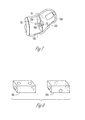
- FIG. 1 illustrates an in-the-ear (ITE) hearing assistance device configured to improve speech intelligibility of sounds from the wearer's mouth, according to one embodiment of the present subject matter.
- ITE in-the-ear
- FIG. 2 illustrates an ITE hearing assistance device configured to improve speech intelligibility of sounds from the wearer's mouth, the device housing including a barrier window, according to one embodiment of the present subject matter.
- FIG. 3 illustrates an ITE hearing assistance device including a vented housing and a barrier window, the device configured to improve speech intelligibility of sounds from the wearer's mouth, according to one embodiment of the present subject matter.
- FIG. 4 illustrates an ITE hearing assistance device including a thin section of housing and a barrier window, the device configured to improve speech intelligibility of sounds from the wearer's mouth, according to one embodiment of the present subject matter.
- FIG. 5 illustrates an ITE hearing assistance device including a differential sensor mounted to an elastomeric suspension, the device configured to improve speech intelligibility of sounds from the wearer's mouth, according to one embodiment of the present subject matter.
- FIG. 6 illustrates an ITE hearing assistance device including a differential sensor integrated into a window barrier, the device configured to improve speech intelligibility of sounds from the wearer's mouth, according to one embodiment of the present subject matter.
- FIG. 7 illustrates an ITE hearing assistance device including a housing divided into multiple separate air cavities, the device configured to improve speech intelligibility of sounds from the wearer's mouth, according to one embodiment of the present subject matter.
- FIG. 8 illustrates second-order pressure differential sensor to be used in an ITE hearing assistance device, the device configured to improve speech intelligibility of sounds from the wearer's mouth, according to one embodiment of the present subject matter.
- FIG. 9 illustrates a combination sensor to be used in an ITE hearing assistance device, the device configured to improve speech intelligibility of sounds from the wearer's mouth, according to one embodiment of the present subject matter.
- FIG. 10 is a graphical diagram illustrating frequency bands for speech intelligibility.
- Modern hearing assistance devices such as hearing aids typically include a processor, such as a digital signal processor in communication with a microphone and receiver. Such designs are adapted to perform a great deal of processing on sounds received by the microphone. These designs can be highly programmable and may use inputs from remote devices, such as wired and wireless devices.
- own-voice is typically detected with some type of boom microphone or directional microphone on the exterior housing.
- own-voice has been previously detected with one (or more) microphones in the faceplate housing.
- In-the-ear (ITE) hearing instruments with sensors positioned along the tip or canal of the earmold rather than the faceplate have also been used. These instruments are targeted for first-responder communication applications such as firefighters and omnidirectional microphones are typically used.
- the acoustical inlet of the omnidirectional microphone can be located at the tip of the earmold so as to sense the sound pressure in the air cavity of the ear canal.
- the microphone is susceptible to foreign debris.
- the plastic ITE housing can contain a small elastomeric bladder with one side-wall of the bladder in contact with the ear canal skin, and the other side of the bladder connected to the microphone inlet, where the inside of the bladder contains a closed air cavity sharing air with the microphone inlet.
- FIG. 10 depicts Speech Intelligibility Index (SH) coefficients, Toward that end, a pressure-differential microphone has an intrinsic response that is commensurate to the SII response and is therefore better suited for own-voice intelligibility. The important frequency bands for speech intelligibility are indicated in the illustrated SII weighted coefficients.
- SH Speech Intelligibility Index
- the present subject matter uses a sensor with a frequency response that resembles the SII weightings.
- omnidirectional microphones have relatively flat frequency responses whereas directional (pressure-differential) microphones have freefield responses that roll off at lower frequencies, thereby resembling the SII weightings as shown above.
- the internal membranes oftypical pressure-differential electret microphones are not loaded with closed air cavities, and for this reason they are more sensitive to bone-conducted vibration than typical omni electret microphones. Differential microphones, therefore, are better suited for this application - not because of their directional polar response in a freefield, but because of their intrinsic frequency response and their susceptibility to bone-conducted vibration.
- the present subject matter includes a differential microphone placed deep in the ear canal, mounted (directly or indirectly) to the plastic ITE housing and contained within the air cavity of the hollow plastic housing.
- Advantages of the present subject matter include: 1) isolation from outside ambient noise, 2) protection from foreign debris, 3) a frequency response that is similar to the SII frequency weightings, and 4) higher sensitivity to bond-conducted vibration. This last item implies that it is advantageous to mount the sensor so as to amplify bone-conducted vibrations in the frequency regions as depicted in the SII weightings.
- the senor could be placed in an elastomeric sleeve so that its resonance frequency, i.e., the compliance of the elastomeric sleeve resonating with the mass of the sensor, enhances the overall response in the SII weighted frequency bands.
- FIG. 1 illustrates an in-the-ear (ITE) hearing assistance device configured to improve speech intelligibility of sounds from the wearer's mouth, according to one embodiment of the present subject matter.
- a differential sensor [200] is mounted rigidly [3] to the hollow plastic housing [100] of the ITE hearing instrument, such that the inlets [2] to differential sensor [200] are all located within closed air cavity [10] of ITE housing [100].
- FIG. 2 illustrates an ITE hearing assistance device configured to improve speech intelligibility of sounds from the wearer's mouth, the device housing including a barrier window, according to one embodiment of the present subject matter.
- the embodiment in FIG. 2 is similar to the embodiment In FIG. 1 except that internal air cavity [10] of hollow plastic housing [100] has a relatively small barrier window [103] positioned at the eartip, proximate to the medial ear canal air cavity.
- Barrier window [103] could also be made of the same material as the housing, or of some other plastic, except that it is thinner than plastic housing [100] in various embodiments.
- Its dimensions and material properties can be engineered to resonate and enhance the differential sensor [200] output in the SII weighted frequency bands.
- the dimensions and material properties of sensor pad [3] also can be engineered to resonate mechanically and enhance the differential sensor [200] output in the SII weighted frequency bands, in various embodiments.
- FIG. 3 illustrates an ITE hearing assistance device including a vented housing and a barrier window, the device configured to improve speech intelligibility of sounds from the wearer's mouth, according to one embodiment of the present subject matter.
- the embodiment in FIG 3 is similar to the embodiment of FIG. 2 , except that ITE housing [100] is vented [101] and the small barrier window [103] is located on the wall of the vent [101] such that the inlets [2] of differential sensor [200] are still positioned within the closed air cavity [10] of ITE housing [100].
- FIG. 4 illustrates an ITE hearing assistance device including a thin section of housing and a barrier window, the device configured to improve speech intelligibility of sounds from the wearer's mouth, according to one embodiment of the present subject matter.
- the embodiment in FIG. 4 is similar to the embodiments of FIGS. 2-3 , except that the small window [103] is located on the side of ITE housing [100] proximate to the ear canal skin.
- a small air cavity [110] is located between the small window [103], alternatively a thin section of the shell itself, and the skin, which is to say, small window [103] is not flush to the skin.
- FIG. 5 illustrates an ITE hearing assistance device including a differential sensor mounted to an elastomeric suspension, the device configured to improve speech intelligibility of sounds from the wearer's mouth, according to one embodiment of the present subject matter.
- the embodiment in FIG. 5 is similar to the previous embodiments except that differential sensor [200] is not rigidly mounted to plastic housing [100] but rather is mounted to an elastomeric suspension [20] whose resonance frequency is engineered to enhance the differential sensor [200] output in the SII weighted frequency bands, in various embodiments,
- FIG. 6 illustrates an ITE hearing assistance device including a differential sensor integrated into a window barrier, the device configured to improve speech intelligibility of sounds from the wearer's mouth, according to one embodiment of the present subject matter.
- the embodiment in FIG 6 is similar to the previous embodiments except that sensor [200] is integrated onto window barrier [120], such that all inlets of sensor [200] remain within hollow plastic housing [100].
- Integrated barrier [120] and sensor [200] have a resonance frequency that is engineered to enhance the sensor output in the SII weighted frequency bands, in various embodiments,
- FIG. 7 illustrates an ITE hearing assistance device including a housing divided into multiple separate air cavities, the device configured to improve speech intelligibility of sounds from the wearer's mouth, according to one embodiment of the present subject matter.
- the ITE housing [100] is divided into two separate air cavities [20] and [30] by barrier [120].
- Differential sensor [200] is integrated into barrier [120] such that acoustical inlet [12] is located within air cavity [20] having a small window barrier [122] and acoustical inlet [13] is located within air cavity [30] having another small window barrier [123], in various embodiments.
- window barriers [122] and [123] could be located on the wall of a vent, as shown in FIG. 3 .
- barrier [120] can be elastomeric or plastic, and engineered to resonate and enhance the sensor output in the SII weighted frequency bands.
- FIG. 8 illustrates second-order pressure differential sensor to be used in an ITE hearing assistance device, the device configured to improve speech intelligibility of sounds from the wearer's mouth, according to one embodiment of the present subject matter.
- FIG. 8 depicts a single, second-order pressure differential sensor which is used in any and all of the above embodiments instead of a first-order pressure differential sensor, thereby increasing its sensitivity to vibration.
- the four inlets can either be arranged linearly, as with a linear quadrupole [201], or as orthogonal pairs [202], as with a tesseral quadrupole.
- FIG, 9 illustrates a combination sensor to be used in an ITE hearing assistance device, the device configured to improve speech intelligibility of sounds from the wearer's mouth, according to one embodiment of the present subject matter.
- the outputs of both an omni [211] and differential [212] sensor are combined to give a system output signal that has extended low frequencies as compared to the output of a differential sensor alone.
- the signals are combined not necessarily to improve speech intelligibility, but to produce sound quality of own-voice that is richer and fuller.
- This combination sensor which can be piggy-backed as shown or conjoined side-by-side, could be used in all of the embodiments shown previously.
- the present subject matter provides ways to arrange and mount a sensor within the housing of an ITE housing instrument so as to improve the speech intelligibility of the sensor's output signal.
- Unique aspects of the present subject matter include, but are not limited to: (1) a single, passive, pressure-differential electret microphone can be used for enhanced speech intelligibility; (2) the passive, pressure-differential microphone can have either a 1 st - or 2 nd -order freefield response; (3) the mounting suspension stiffness is engineered to resonate with the mass of the differential microphone so as to amplify and enhance the sensor's bone-conduction response in the SII weighted frequency bands.
- Engineering includes the choice of elastomer and its geometrical dimensions, particularly its thickness; (4) the tension and effective mass of the elastomeric window barrier, integrated into the wall of the plastic housing, is engineered to resonate with the stiffness of the air cavity within the plastic housing so as to amplify and enhance the sensor's response in the SII weighted frequency bands.
- Engineering includes the choice of elastomer and its geometrical dimensions, particularly its thickness; and (5) a combination module containing both an omni and pressure-differential sensor can be used to extend low frequencies for a sound quality of own-voice that is fuller.
- a sensor comprising a single electret microphone consumes less electrical power than multi-microphone approaches; (2) a sensor comprising a single, pressure-differential electret microphone is more sensitive to bone-conducted vibration as compared to an omni electret microphone; (3) a sensor comprising a single, piezoceramic microphone is more sensitive to bone-conducted vibration as compared to an omni electret microphone; (4) the mounting of the sensor does not require any specialty bladders or pillows that protrude out of the shell, thereby causing potential discomfort to the user; (5) the sensor is located inside of the ITE earmold thereby protecting it from foreign debris; and (6) the output of a second omni sensor can be combined with the output of the differential sensor to extend low frequencies and provide a fuller quality of sound to own-voice.
- Additional embodiments of the present subject matter include, but are not limited to; (1) using a piezoceramic microphone instead of an electret microphone. Piezoceramic microphones were used in hearing instruments briefly in the early 1970's, and are intrinsically more sensitive to (bone conduction) vibration than typical electrets. The piezoceramic microphone can either be omni or differential; (2) using a silicon MEMS microphone instead of an electret microphone. MEMS microphones are used considerably in today's telecom instruments, and may be more sensitive to (bone conduction) vibration than typical electrets. The MEMS microphone can either be omni or differential; (3) in each above embodiment, the output signal of a separate faceplate microphone could be used in a digital signal processing method to enhance the quality of the own-voice sensor signal.
- the faceplate microphone output signal could be combined with the own-voice sensor signal to produce an enhanced system output signal.
- the faceplate microphone output signal could be cross-correlated with the own-voice sensor signal to determine when the user is actually talking, thereby gating the transmission of the own-voice signal; (4) in each above embodiment having a pressure-differential sensor whose output signal is inherently deficient of low frequency energy, a DSP scheme using psychoacoustic bass-enhancement algorithms can be used to artificially extend and enhance the perception of the low-frequency harmonics (60 to 250 Hz) of the speech signal, thereby providing a fuller, richer sound quality of own-voice.
- Benefits of the present subject matter include, but are not limited to: (1) provides higher speech intelligibility; (2) provides protection against foreign debris, (3) uses a pressure-differential sensor that is more susceptible to bone-conducted vibration, (4) uses a pressure-differential sensor that enhances the response in the critical frequency regions for speech intelligibility, (5) uses a suspension system whose resonance frequency is tuned to enhance the response in the critical frequency regions for speech intelligibility, (6) uses a secondary omnidirectional sensor to enhance the fullness of sound quality for own-voice, (7) uses a piezoceramic sensor that is more susceptible to bone-conducted vibration, (8) uses a differential sensor and a DSP algorithm to extend and enhance the low frequency harmonics of the speech signal, thereby providing a fuller, richer sound quality of own voice, (9) uses a faceplate microphone together with a DSP algorithm to gate the transmission of the own-voice signal, uses a faceplate microphone together with a DSP algorithm to
- Hearing assistance devices typically include an enclosure or housing, a microphone, hearing assistance device electronics including processing electronics, and a speaker or receiver.
- Processing electronics include a controller or processor, such as a digital signal processor (DSP), in various embodiments, Other types of processors may be used without departing from the scope of this disclosure.
- DSP digital signal processor
- the microphone is optional.
- the receiver is optional.
- the hearing aids referenced in this patent application include a processor.
- the processor may be a digital signal processor (DSP), microprocessor, microcontroller, other digital logic, or combinations thereof.
- DSP digital signal processor
- the processing of signals referenced in this application can be performed using the processor. Processing may be done in the digital domain, the analog domain, or combinations thereof. Processing may be done using subband processing techniques. Processing may be done with frequency domain or time domain approaches. Some processing may involve both frequency and time domain aspects. For brevet, in some examples drawings may omit certain blocks that perform frequency synthesis, frequency analysis, analog-to-digital conversion, digital-to-analog conversion, amplification, and certain types of filtering and processing.
- the processor is adapted to perform instructions stored in memory which may or may not be explicitly shown.
- memory may be used, including volatile and nonvolatile forms of memory.
- instructions are performed by the processor to perform a number of signal processing tasks.
- analog components are in communication with the processor to perform signaltasks, such as microphone reception, or receiver sound embodiments (i.e., in applications where such transducers are used).
- signaltasks such as microphone reception, or receiver sound embodiments (i.e., in applications where such transducers are used).
- different realizations of the block diagrams, circuits, and processes set forth herein may occur without departing from the scope of the present subject matter.
- hearing assistance devices including hearing aids, including but not limited to, behind-the-ear (BTE), in-the-ear (ITE), in-the-canal (ITC), receiver-in-canal (RIC), or completely-in-the-canal (CIC) type hearing aids.
- BTE behind-the-ear
- ITE in-the-ear
- ITC in-the-canal
- RIC receiver-in-canal
- CIC completely-in-the-canal
- hearing assistance devices including but not limited to, behind-the-ear (BTE), in-the-ear (ITE), in-the-canal (ITC), receiver-in-canal (RIC), or completely-in-the-canal (CIC) type hearing aids.
- BTE behind-the-ear
- ITE in-the-ear
- ITC in-the-canal
- RIC receiver-in-canal
- CIC completely-in-the-canal
- hearing assistance devices including but not limited to, behind-the-ear (BTE), in
- the present subject matter can also be used in hearing assistance devices generally, such as cochlear implant type hearing devices and such as deep insertion devices having a transducer, such as a receiver or microphone, whether custom fitted, standard, open fitted or occlusive fitted. It is understood that other hearing assistance devices not expressly stated herein may be used in conjunction with the present subject matter.
Applications Claiming Priority (1)
| Application Number | Priority Date | Filing Date | Title |
|---|---|---|---|
| US201261682589P | 2012-08-13 | 2012-08-13 |
Publications (2)
| Publication Number | Publication Date |
|---|---|
| EP2699021A1 true EP2699021A1 (de) | 2014-02-19 |
| EP2699021B1 EP2699021B1 (de) | 2016-07-06 |
Family
ID=48918316
Family Applications (1)
| Application Number | Title | Priority Date | Filing Date |
|---|---|---|---|
| EP13179859.7A Active EP2699021B1 (de) | 2012-08-13 | 2013-08-09 | Verfahren und Vorrichtung zur Messung der eigenen Stimme in einer Hörhilfevorrichtung |
Country Status (3)
| Country | Link |
|---|---|
| US (5) | US9042586B2 (de) |
| EP (1) | EP2699021B1 (de) |
| DK (1) | DK2699021T3 (de) |
Cited By (1)
| Publication number | Priority date | Publication date | Assignee | Title |
|---|---|---|---|---|
| EP3684074A1 (de) | 2019-03-29 | 2020-07-22 | Sonova AG | Hörgerät zur eigenen spracherkennung und verfahren zum betrieb des hörgeräts |
Families Citing this family (14)
| Publication number | Priority date | Publication date | Assignee | Title |
|---|---|---|---|---|
| US10334370B2 (en) * | 2009-07-25 | 2019-06-25 | Eargo, Inc. | Apparatus, system and method for reducing acoustic feedback interference signals |
| DK2699021T3 (en) | 2012-08-13 | 2016-09-26 | Starkey Labs Inc | Method and apparatus for self-voice detection in a hearing-aid |
| JP2014155145A (ja) * | 2013-02-13 | 2014-08-25 | Funai Electric Co Ltd | イヤホンマイク |
| JP2015023495A (ja) * | 2013-07-22 | 2015-02-02 | 船井電機株式会社 | イヤホンマイク |
| US20150118960A1 (en) * | 2013-10-28 | 2015-04-30 | Aliphcom | Wearable communication device |
| US9596536B2 (en) | 2015-07-22 | 2017-03-14 | Google Inc. | Microphone arranged in cavity for enhanced voice isolation |
| EP3151583B1 (de) * | 2015-09-30 | 2022-02-02 | Apple Inc. | Ohrhörergehäuse mit buchsenstecker für ohrhörer |
| US10021494B2 (en) | 2015-10-14 | 2018-07-10 | Sonion Nederland B.V. | Hearing device with vibration sensitive transducer |
| WO2017118878A1 (en) * | 2016-01-07 | 2017-07-13 | Sonova Ag | Hearing assistance device transducers and hearing assistance devices with same |
| DE102017114008A1 (de) | 2017-06-23 | 2018-12-27 | USound GmbH | In-Ohr Hörer |
| EP3580639A1 (de) | 2018-02-09 | 2019-12-18 | Starkey Laboratories, Inc. | Verwendung von periaurikulären muskelsignalen zur schätzung der richtung eines höraufmerksamkeitsortes eines benutzers |
| EP3525490A1 (de) * | 2018-02-13 | 2019-08-14 | Oticon A/s | In-ohr-hörgerät, hörgerät und elektro-akustischer wandler |
| EP3627848A1 (de) | 2018-09-20 | 2020-03-25 | Sonova AG | Verfahren zum betrieb eines hörgeräts sowie hörgerät mit einer aktiven entlüftung |
| US20230300509A1 (en) | 2022-03-15 | 2023-09-21 | Starkey Laboratories, Inc. | Hearing device |
Citations (6)
| Publication number | Priority date | Publication date | Assignee | Title |
|---|---|---|---|---|
| US5692059A (en) | 1995-02-24 | 1997-11-25 | Kruger; Frederick M. | Two active element in-the-ear microphone system |
| US20070127757A2 (en) | 2005-07-18 | 2007-06-07 | Soundquest, Inc. | Behind-The-Ear-Auditory Device |
| US20100119086A1 (en) * | 2007-02-28 | 2010-05-13 | Temco Japan Co., Ltd. | Vibration pickup microphone |
| US20100172523A1 (en) * | 2008-12-31 | 2010-07-08 | Starkey Laboratories, Inc. | Method and apparatus for detecting user activities from within a hearing assistance device using a vibration sensor |
| US20100246860A1 (en) * | 2009-03-27 | 2010-09-30 | Motorola, Inc. | Bone conduction assembly for communication headset |
| US20110243385A1 (en) | 2010-03-30 | 2011-10-06 | Sony Corporation | Moving object detection apparatus, moving object detection method, and program |
Family Cites Families (25)
| Publication number | Priority date | Publication date | Assignee | Title |
|---|---|---|---|---|
| US2832842A (en) * | 1952-07-17 | 1958-04-29 | Sonotone Corp | Body contacting inertia reaction electromechanical transducing devices |
| US4150262A (en) | 1974-11-18 | 1979-04-17 | Hiroshi Ono | Piezoelectric bone conductive in ear voice sounds transmitting and receiving apparatus |
| DK164349C (da) * | 1989-08-22 | 1992-11-02 | Oticon As | Hoereapparat med tilbagekoblingskompensation |
| US5812659A (en) | 1992-05-11 | 1998-09-22 | Jabra Corporation | Ear microphone with enhanced sensitivity |
| US5524056A (en) * | 1993-04-13 | 1996-06-04 | Etymotic Research, Inc. | Hearing aid having plural microphones and a microphone switching system |
| US6366678B1 (en) * | 1999-01-07 | 2002-04-02 | Sarnoff Corporation | Microphone assembly for hearing aid with JFET flip-chip buffer |
| US6754359B1 (en) | 2000-09-01 | 2004-06-22 | Nacre As | Ear terminal with microphone for voice pickup |
| AU2003247271A1 (en) | 2002-09-02 | 2004-03-19 | Oticon A/S | Method for counteracting the occlusion effects |
| WO2004068464A2 (en) * | 2003-01-30 | 2004-08-12 | Aliphcom, Inc. | Acoustic vibration sensor |
| US20050058313A1 (en) | 2003-09-11 | 2005-03-17 | Victorian Thomas A. | External ear canal voice detection |
| DE102005032274B4 (de) | 2005-07-11 | 2007-05-10 | Siemens Audiologische Technik Gmbh | Hörvorrichtung und entsprechendes Verfahren zur Eigenstimmendetektion |
| US7502484B2 (en) | 2006-06-14 | 2009-03-10 | Think-A-Move, Ltd. | Ear sensor assembly for speech processing |
| CN101480069A (zh) | 2006-08-07 | 2009-07-08 | 唯听助听器公司 | 用于原位阻塞效应和直接传输声音测量的助听器和方法及通气孔大小确定方法 |
| US8611560B2 (en) * | 2007-04-13 | 2013-12-17 | Navisense | Method and device for voice operated control |
| US8503686B2 (en) * | 2007-05-25 | 2013-08-06 | Aliphcom | Vibration sensor and acoustic voice activity detection system (VADS) for use with electronic systems |
| CA2690238A1 (en) | 2007-06-13 | 2008-12-18 | Widex A/S | A system and a method for establishing a conversation group among a number of hearing aids |
| WO2008151624A1 (en) | 2007-06-13 | 2008-12-18 | Widex A/S | Hearing aid system establishing a conversation group among hearing aids used by different users |
| DK2040490T4 (da) * | 2007-09-18 | 2021-04-12 | Starkey Labs Inc | Fremgangsmåde og apparat til en hørehjælpsanordning ved anvendelse af mems-sensorer |
| US8265316B2 (en) * | 2008-03-20 | 2012-09-11 | Siemens Medical Instruments Pte. Ltd. | Hearing aid with enhanced vent |
| US8483418B2 (en) | 2008-10-09 | 2013-07-09 | Phonak Ag | System for picking-up a user's voice |
| US8600090B2 (en) * | 2009-03-13 | 2013-12-03 | Siemens Medical Instruments Pte. Ltd. | Hearing aid and in-the-ear-device |
| US8477973B2 (en) | 2009-04-01 | 2013-07-02 | Starkey Laboratories, Inc. | Hearing assistance system with own voice detection |
| US8705787B2 (en) | 2009-12-09 | 2014-04-22 | Nextlink Ipr Ab | Custom in-ear headset |
| US9326078B2 (en) | 2012-07-23 | 2016-04-26 | Starkey Laboratories, Inc. | Methods and apparatus for improving speech understanding in a large crowd |
| DK2699021T3 (en) | 2012-08-13 | 2016-09-26 | Starkey Labs Inc | Method and apparatus for self-voice detection in a hearing-aid |
-
2013
- 2013-08-09 DK DK13179859.7T patent/DK2699021T3/en active
- 2013-08-09 EP EP13179859.7A patent/EP2699021B1/de active Active
- 2013-08-13 US US13/966,058 patent/US9042586B2/en active Active
-
2015
- 2015-05-22 US US14/720,036 patent/US9900710B2/en active Active
-
2018
- 2018-01-31 US US15/884,850 patent/US10880657B2/en active Active
-
2020
- 2020-12-23 US US17/247,821 patent/US11856371B2/en active Active
-
2023
- 2023-11-20 US US18/514,140 patent/US20240089677A1/en active Pending
Patent Citations (6)
| Publication number | Priority date | Publication date | Assignee | Title |
|---|---|---|---|---|
| US5692059A (en) | 1995-02-24 | 1997-11-25 | Kruger; Frederick M. | Two active element in-the-ear microphone system |
| US20070127757A2 (en) | 2005-07-18 | 2007-06-07 | Soundquest, Inc. | Behind-The-Ear-Auditory Device |
| US20100119086A1 (en) * | 2007-02-28 | 2010-05-13 | Temco Japan Co., Ltd. | Vibration pickup microphone |
| US20100172523A1 (en) * | 2008-12-31 | 2010-07-08 | Starkey Laboratories, Inc. | Method and apparatus for detecting user activities from within a hearing assistance device using a vibration sensor |
| US20100246860A1 (en) * | 2009-03-27 | 2010-09-30 | Motorola, Inc. | Bone conduction assembly for communication headset |
| US20110243385A1 (en) | 2010-03-30 | 2011-10-06 | Sony Corporation | Moving object detection apparatus, moving object detection method, and program |
Cited By (1)
| Publication number | Priority date | Publication date | Assignee | Title |
|---|---|---|---|---|
| EP3684074A1 (de) | 2019-03-29 | 2020-07-22 | Sonova AG | Hörgerät zur eigenen spracherkennung und verfahren zum betrieb des hörgeräts |
Also Published As
| Publication number | Publication date |
|---|---|
| US20240089677A1 (en) | 2024-03-14 |
| US10880657B2 (en) | 2020-12-29 |
| US20150334492A1 (en) | 2015-11-19 |
| US20140044294A1 (en) | 2014-02-13 |
| US11856371B2 (en) | 2023-12-26 |
| US9042586B2 (en) | 2015-05-26 |
| EP2699021B1 (de) | 2016-07-06 |
| US20210120347A1 (en) | 2021-04-22 |
| US9900710B2 (en) | 2018-02-20 |
| DK2699021T3 (en) | 2016-09-26 |
| US20180160238A1 (en) | 2018-06-07 |
Similar Documents
| Publication | Publication Date | Title |
|---|---|---|
| US11856371B2 (en) | Method and apparatus for own-voice sensing in a hearing assistance device | |
| CN106937196B (zh) | 头戴式听力设备 | |
| US8150084B2 (en) | Hearing aid and a method of processing a sound signal in a hearing aid | |
| EP2405674B1 (de) | Hörhilfe mit Einschlussunterdrückung | |
| EP1681904B1 (de) | Hinter-dem-Ohr-Hörgerät | |
| US11432085B2 (en) | Occlusion control system for a hearing instrument and a hearing instrument | |
| EP3099082A1 (de) | Rückhaltearm mit selbstausrichtender komfortpassform für eine hörhilfevorrichtung | |
| US10616685B2 (en) | Method and device for streaming communication between hearing devices | |
| US10993055B2 (en) | Elastomeric wax barrier for hearing aid acoustic port | |
| EP3324644B1 (de) | Drahtloses hörgerät mit stabilisator zwischen tragus und antitragus | |
| US20230319495A1 (en) | Hearing device | |
| EP4254984A1 (de) | Hörgerät | |
| US20230319494A1 (en) | Hearing device | |
| EP3866484B1 (de) | Kehlkopf-headset-system | |
| EP4254980A1 (de) | Hörvorrichtung | |
| CN109040931B (zh) | 用于听力仪器的堵塞控制系统和听力仪器 |
Legal Events
| Date | Code | Title | Description |
|---|---|---|---|
| 17P | Request for examination filed |
Effective date: 20130809 |
|
| AK | Designated contracting states |
Kind code of ref document: A1 Designated state(s): AL AT BE BG CH CY CZ DE DK EE ES FI FR GB GR HR HU IE IS IT LI LT LU LV MC MK MT NL NO PL PT RO RS SE SI SK SM TR |
|
| AX | Request for extension of the european patent |
Extension state: BA ME |
|
| PUAI | Public reference made under article 153(3) epc to a published international application that has entered the european phase |
Free format text: ORIGINAL CODE: 0009012 |
|
| 17Q | First examination report despatched |
Effective date: 20141202 |
|
| GRAP | Despatch of communication of intention to grant a patent |
Free format text: ORIGINAL CODE: EPIDOSNIGR1 |
|
| RIC1 | Information provided on ipc code assigned before grant |
Ipc: H04R 25/00 20060101AFI20151218BHEP Ipc: H04R 1/38 20060101ALN20151218BHEP |
|
| INTG | Intention to grant announced |
Effective date: 20160120 |
|
| GRAS | Grant fee paid |
Free format text: ORIGINAL CODE: EPIDOSNIGR3 |
|
| GRAA | (expected) grant |
Free format text: ORIGINAL CODE: 0009210 |
|
| AK | Designated contracting states |
Kind code of ref document: B1 Designated state(s): AL AT BE BG CH CY CZ DE DK EE ES FI FR GB GR HR HU IE IS IT LI LT LU LV MC MK MT NL NO PL PT RO RS SE SI SK SM TR |
|
| REG | Reference to a national code |
Ref country code: GB Ref legal event code: FG4D |
|
| REG | Reference to a national code |
Ref country code: AT Ref legal event code: REF Ref document number: 811443 Country of ref document: AT Kind code of ref document: T Effective date: 20160715 Ref country code: CH Ref legal event code: EP Ref country code: CH Ref legal event code: NV Representative=s name: MARKS AND CLERK (LUXEMBOURG) LLP, CH |
|
| REG | Reference to a national code |
Ref country code: IE Ref legal event code: FG4D |
|
| REG | Reference to a national code |
Ref country code: DE Ref legal event code: R096 Ref document number: 602013009071 Country of ref document: DE |
|
| REG | Reference to a national code |
Ref country code: FR Ref legal event code: PLFP Year of fee payment: 4 |
|
| REG | Reference to a national code |
Ref country code: DK Ref legal event code: T3 Effective date: 20160921 |
|
| REG | Reference to a national code |
Ref country code: NL Ref legal event code: MP Effective date: 20160706 |
|
| REG | Reference to a national code |
Ref country code: LT Ref legal event code: MG4D |
|
| REG | Reference to a national code |
Ref country code: AT Ref legal event code: MK05 Ref document number: 811443 Country of ref document: AT Kind code of ref document: T Effective date: 20160706 |
|
| PG25 | Lapsed in a contracting state [announced via postgrant information from national office to epo] |
Ref country code: BE Free format text: LAPSE BECAUSE OF NON-PAYMENT OF DUE FEES Effective date: 20160831 |
|
| PG25 | Lapsed in a contracting state [announced via postgrant information from national office to epo] |
Ref country code: HR Free format text: LAPSE BECAUSE OF FAILURE TO SUBMIT A TRANSLATION OF THE DESCRIPTION OR TO PAY THE FEE WITHIN THE PRESCRIBED TIME-LIMIT Effective date: 20160706 Ref country code: NO Free format text: LAPSE BECAUSE OF FAILURE TO SUBMIT A TRANSLATION OF THE DESCRIPTION OR TO PAY THE FEE WITHIN THE PRESCRIBED TIME-LIMIT Effective date: 20161006 Ref country code: LT Free format text: LAPSE BECAUSE OF FAILURE TO SUBMIT A TRANSLATION OF THE DESCRIPTION OR TO PAY THE FEE WITHIN THE PRESCRIBED TIME-LIMIT Effective date: 20160706 Ref country code: NL Free format text: LAPSE BECAUSE OF FAILURE TO SUBMIT A TRANSLATION OF THE DESCRIPTION OR TO PAY THE FEE WITHIN THE PRESCRIBED TIME-LIMIT Effective date: 20160706 Ref country code: IS Free format text: LAPSE BECAUSE OF FAILURE TO SUBMIT A TRANSLATION OF THE DESCRIPTION OR TO PAY THE FEE WITHIN THE PRESCRIBED TIME-LIMIT Effective date: 20161106 Ref country code: RS Free format text: LAPSE BECAUSE OF FAILURE TO SUBMIT A TRANSLATION OF THE DESCRIPTION OR TO PAY THE FEE WITHIN THE PRESCRIBED TIME-LIMIT Effective date: 20160706 Ref country code: FI Free format text: LAPSE BECAUSE OF FAILURE TO SUBMIT A TRANSLATION OF THE DESCRIPTION OR TO PAY THE FEE WITHIN THE PRESCRIBED TIME-LIMIT Effective date: 20160706 Ref country code: IT Free format text: LAPSE BECAUSE OF FAILURE TO SUBMIT A TRANSLATION OF THE DESCRIPTION OR TO PAY THE FEE WITHIN THE PRESCRIBED TIME-LIMIT Effective date: 20160706 |
|
| PG25 | Lapsed in a contracting state [announced via postgrant information from national office to epo] |
Ref country code: LV Free format text: LAPSE BECAUSE OF FAILURE TO SUBMIT A TRANSLATION OF THE DESCRIPTION OR TO PAY THE FEE WITHIN THE PRESCRIBED TIME-LIMIT Effective date: 20160706 Ref country code: PT Free format text: LAPSE BECAUSE OF FAILURE TO SUBMIT A TRANSLATION OF THE DESCRIPTION OR TO PAY THE FEE WITHIN THE PRESCRIBED TIME-LIMIT Effective date: 20161107 Ref country code: ES Free format text: LAPSE BECAUSE OF FAILURE TO SUBMIT A TRANSLATION OF THE DESCRIPTION OR TO PAY THE FEE WITHIN THE PRESCRIBED TIME-LIMIT Effective date: 20160706 Ref country code: GR Free format text: LAPSE BECAUSE OF FAILURE TO SUBMIT A TRANSLATION OF THE DESCRIPTION OR TO PAY THE FEE WITHIN THE PRESCRIBED TIME-LIMIT Effective date: 20161007 Ref country code: PL Free format text: LAPSE BECAUSE OF FAILURE TO SUBMIT A TRANSLATION OF THE DESCRIPTION OR TO PAY THE FEE WITHIN THE PRESCRIBED TIME-LIMIT Effective date: 20160706 Ref country code: SE Free format text: LAPSE BECAUSE OF FAILURE TO SUBMIT A TRANSLATION OF THE DESCRIPTION OR TO PAY THE FEE WITHIN THE PRESCRIBED TIME-LIMIT Effective date: 20160706 Ref country code: BE Free format text: LAPSE BECAUSE OF FAILURE TO SUBMIT A TRANSLATION OF THE DESCRIPTION OR TO PAY THE FEE WITHIN THE PRESCRIBED TIME-LIMIT Effective date: 20160706 Ref country code: AT Free format text: LAPSE BECAUSE OF FAILURE TO SUBMIT A TRANSLATION OF THE DESCRIPTION OR TO PAY THE FEE WITHIN THE PRESCRIBED TIME-LIMIT Effective date: 20160706 |
|
| REG | Reference to a national code |
Ref country code: DE Ref legal event code: R097 Ref document number: 602013009071 Country of ref document: DE |
|
| PG25 | Lapsed in a contracting state [announced via postgrant information from national office to epo] |
Ref country code: MC Free format text: LAPSE BECAUSE OF FAILURE TO SUBMIT A TRANSLATION OF THE DESCRIPTION OR TO PAY THE FEE WITHIN THE PRESCRIBED TIME-LIMIT Effective date: 20160706 Ref country code: RO Free format text: LAPSE BECAUSE OF FAILURE TO SUBMIT A TRANSLATION OF THE DESCRIPTION OR TO PAY THE FEE WITHIN THE PRESCRIBED TIME-LIMIT Effective date: 20160706 Ref country code: EE Free format text: LAPSE BECAUSE OF FAILURE TO SUBMIT A TRANSLATION OF THE DESCRIPTION OR TO PAY THE FEE WITHIN THE PRESCRIBED TIME-LIMIT Effective date: 20160706 |
|
| PLBE | No opposition filed within time limit |
Free format text: ORIGINAL CODE: 0009261 |
|
| STAA | Information on the status of an ep patent application or granted ep patent |
Free format text: STATUS: NO OPPOSITION FILED WITHIN TIME LIMIT |
|
| PG25 | Lapsed in a contracting state [announced via postgrant information from national office to epo] |
Ref country code: SM Free format text: LAPSE BECAUSE OF FAILURE TO SUBMIT A TRANSLATION OF THE DESCRIPTION OR TO PAY THE FEE WITHIN THE PRESCRIBED TIME-LIMIT Effective date: 20160706 Ref country code: BG Free format text: LAPSE BECAUSE OF FAILURE TO SUBMIT A TRANSLATION OF THE DESCRIPTION OR TO PAY THE FEE WITHIN THE PRESCRIBED TIME-LIMIT Effective date: 20161006 Ref country code: SK Free format text: LAPSE BECAUSE OF FAILURE TO SUBMIT A TRANSLATION OF THE DESCRIPTION OR TO PAY THE FEE WITHIN THE PRESCRIBED TIME-LIMIT Effective date: 20160706 Ref country code: CZ Free format text: LAPSE BECAUSE OF FAILURE TO SUBMIT A TRANSLATION OF THE DESCRIPTION OR TO PAY THE FEE WITHIN THE PRESCRIBED TIME-LIMIT Effective date: 20160706 |
|
| REG | Reference to a national code |
Ref country code: IE Ref legal event code: MM4A |
|
| 26N | No opposition filed |
Effective date: 20170407 |
|
| REG | Reference to a national code |
Ref country code: FR Ref legal event code: PLFP Year of fee payment: 5 |
|
| PG25 | Lapsed in a contracting state [announced via postgrant information from national office to epo] |
Ref country code: IE Free format text: LAPSE BECAUSE OF NON-PAYMENT OF DUE FEES Effective date: 20160809 |
|
| PG25 | Lapsed in a contracting state [announced via postgrant information from national office to epo] |
Ref country code: SI Free format text: LAPSE BECAUSE OF FAILURE TO SUBMIT A TRANSLATION OF THE DESCRIPTION OR TO PAY THE FEE WITHIN THE PRESCRIBED TIME-LIMIT Effective date: 20160706 Ref country code: LU Free format text: LAPSE BECAUSE OF NON-PAYMENT OF DUE FEES Effective date: 20160809 |
|
| GBPC | Gb: european patent ceased through non-payment of renewal fee |
Effective date: 20170809 |
|
| PG25 | Lapsed in a contracting state [announced via postgrant information from national office to epo] |
Ref country code: CY Free format text: LAPSE BECAUSE OF FAILURE TO SUBMIT A TRANSLATION OF THE DESCRIPTION OR TO PAY THE FEE WITHIN THE PRESCRIBED TIME-LIMIT Effective date: 20160706 Ref country code: HU Free format text: LAPSE BECAUSE OF FAILURE TO SUBMIT A TRANSLATION OF THE DESCRIPTION OR TO PAY THE FEE WITHIN THE PRESCRIBED TIME-LIMIT; INVALID AB INITIO Effective date: 20130809 |
|
| PG25 | Lapsed in a contracting state [announced via postgrant information from national office to epo] |
Ref country code: MT Free format text: LAPSE BECAUSE OF NON-PAYMENT OF DUE FEES Effective date: 20160831 Ref country code: MK Free format text: LAPSE BECAUSE OF FAILURE TO SUBMIT A TRANSLATION OF THE DESCRIPTION OR TO PAY THE FEE WITHIN THE PRESCRIBED TIME-LIMIT Effective date: 20160706 Ref country code: TR Free format text: LAPSE BECAUSE OF FAILURE TO SUBMIT A TRANSLATION OF THE DESCRIPTION OR TO PAY THE FEE WITHIN THE PRESCRIBED TIME-LIMIT Effective date: 20160706 |
|
| REG | Reference to a national code |
Ref country code: FR Ref legal event code: PLFP Year of fee payment: 6 |
|
| PG25 | Lapsed in a contracting state [announced via postgrant information from national office to epo] |
Ref country code: GB Free format text: LAPSE BECAUSE OF NON-PAYMENT OF DUE FEES Effective date: 20170809 |
|
| PG25 | Lapsed in a contracting state [announced via postgrant information from national office to epo] |
Ref country code: AL Free format text: LAPSE BECAUSE OF FAILURE TO SUBMIT A TRANSLATION OF THE DESCRIPTION OR TO PAY THE FEE WITHIN THE PRESCRIBED TIME-LIMIT Effective date: 20160706 |
|
| P01 | Opt-out of the competence of the unified patent court (upc) registered |
Effective date: 20230610 |
|
| PGFP | Annual fee paid to national office [announced via postgrant information from national office to epo] |
Ref country code: CH Payment date: 20230902 Year of fee payment: 11 |
|
| PGFP | Annual fee paid to national office [announced via postgrant information from national office to epo] |
Ref country code: FR Payment date: 20230726 Year of fee payment: 11 Ref country code: DK Payment date: 20230727 Year of fee payment: 11 Ref country code: DE Payment date: 20230728 Year of fee payment: 11 |