EP2698613A2 - Tuyau de niveau et procédé de mesure d'un niveau d'eau dans un trou de forage - Google Patents
Tuyau de niveau et procédé de mesure d'un niveau d'eau dans un trou de forage Download PDFInfo
- Publication number
- EP2698613A2 EP2698613A2 EP13003515.7A EP13003515A EP2698613A2 EP 2698613 A2 EP2698613 A2 EP 2698613A2 EP 13003515 A EP13003515 A EP 13003515A EP 2698613 A2 EP2698613 A2 EP 2698613A2
- Authority
- EP
- European Patent Office
- Prior art keywords
- level
- water
- borehole
- computer
- mass flow
- Prior art date
- Legal status (The legal status is an assumption and is not a legal conclusion. Google has not performed a legal analysis and makes no representation as to the accuracy of the status listed.)
- Withdrawn
Links
- XLYOFNOQVPJJNP-UHFFFAOYSA-N water Substances O XLYOFNOQVPJJNP-UHFFFAOYSA-N 0.000 title claims abstract description 57
- 238000000034 method Methods 0.000 title claims abstract description 18
- 239000000725 suspension Substances 0.000 claims abstract description 29
- 238000005259 measurement Methods 0.000 abstract description 9
- 239000000523 sample Substances 0.000 description 12
- 229910000679 solder Inorganic materials 0.000 description 6
- 238000002347 injection Methods 0.000 description 4
- 239000007924 injection Substances 0.000 description 4
- 230000006835 compression Effects 0.000 description 2
- 238000007906 compression Methods 0.000 description 2
- 239000011440 grout Substances 0.000 description 2
- 230000003068 static effect Effects 0.000 description 2
- 238000007796 conventional method Methods 0.000 description 1
- 230000000694 effects Effects 0.000 description 1
- 239000007789 gas Substances 0.000 description 1
- 230000002093 peripheral effect Effects 0.000 description 1
- 239000002689 soil Substances 0.000 description 1
Images
Classifications
-
- G—PHYSICS
- G01—MEASURING; TESTING
- G01F—MEASURING VOLUME, VOLUME FLOW, MASS FLOW OR LIQUID LEVEL; METERING BY VOLUME
- G01F23/00—Indicating or measuring liquid level or level of fluent solid material, e.g. indicating in terms of volume or indicating by means of an alarm
- G01F23/22—Indicating or measuring liquid level or level of fluent solid material, e.g. indicating in terms of volume or indicating by means of an alarm by measuring physical variables, other than linear dimensions, pressure or weight, dependent on the level to be measured, e.g. by difference of heat transfer of steam or water
-
- G—PHYSICS
- G01—MEASURING; TESTING
- G01F—MEASURING VOLUME, VOLUME FLOW, MASS FLOW OR LIQUID LEVEL; METERING BY VOLUME
- G01F23/00—Indicating or measuring liquid level or level of fluent solid material, e.g. indicating in terms of volume or indicating by means of an alarm
- G01F23/80—Arrangements for signal processing
-
- G—PHYSICS
- G01—MEASURING; TESTING
- G01F—MEASURING VOLUME, VOLUME FLOW, MASS FLOW OR LIQUID LEVEL; METERING BY VOLUME
- G01F15/00—Details of, or accessories for, apparatus of groups G01F1/00 - G01F13/00 insofar as such details or appliances are not adapted to particular types of such apparatus
- G01F15/07—Integration to give total flow, e.g. using mechanically-operated integrating mechanism
- G01F15/075—Integration to give total flow, e.g. using mechanically-operated integrating mechanism using electrically-operated integrating means
- G01F15/0755—Integration to give total flow, e.g. using mechanically-operated integrating mechanism using electrically-operated integrating means involving digital counting
Definitions
- the present invention relates to a standpipe open at its lower end and to a method for measuring the level of water in a wellbore with a gauge tube open at its lower end and its lower end reaching below the level of the water in the wellbore.
- geothermal probes For the introduction of geothermal probes in the ground, it is necessary to first produce a borehole, in which then the geothermal probe, such as a hose or pipe, can be lowered and positioned. After positioning, the geothermal probe is filled with water and then closed. The internal pressure of the water in the geothermal probe is measured and recorded.
- the geothermal probe such as a hose or pipe
- a suspension is pumped via a grout into the well.
- the injection pipe usually extends down to the lower end of the borehole in order to ensure a complete backfilling. The suspension pressed into the borehole pushes up the water standing in the borehole, if water in the
- the change in the water level or the level of the suspension when there is no water in the borehole should be documented in the borehole.
- a so-called light solder is lowered into the borehole before the sinking of the geothermal probe.
- the light solder is a sensor attached to a measuring tape which, for example, detects and signals the reaching of the water level by a conductivity measurement.
- the level of the water in the borehole can be read before Einteufen the geothermal probe.
- the water level is also measured during the subsequent pressing process at intervals with the light solder. This is associated with an increased workload, because the light solder has to be dropped down into the borehole again and again and the water level has to be read off.
- level tube which is open at its lower end and closed at its upper end.
- the level tube is lowered so far into the borehole that its lower end is below the level of the water or the suspension in the borehole reaches. If the level of the water or the suspension in the borehole changes, the air pressure in the well also changes. This pressure change can be measured and converted by a computer into a new water level. However, this level measurement is inaccurate, because the pressure change can also be caused by factors other than the change in the water level in the borehole.
- the object is achieved for a generic device in that the level pipe or a connecting pipe connected to the level pipe has an outflow, in the level pipe, arranged in the connecting line and / or in the discharge opening a mass flow meter and the mass flow meter is connected to a computer, with a Volume of air flowing through the mass flow meter can be converted into a level of water or a suspension in a borehole.
- the level tube has an outflow for effluent from the level pipe air and in the outflow, a connecting line between the level tube and the discharge or in the level tube mass flow meter is arranged, with the mass flow meter through the volume the level tube and / or the connecting line measured air flowing and using a computer connected to the mass flow meter, the volume of air measured by the mass flow meter is converted into a water level or a suspension in the borehole and output.
- the mass flow meter is a sensor that measures the mass flow of gases. If the level of the water in the pipe changes, the air column on the water in the pipe is also moved. This movement of the air is evaluated with the mass flow meter.
- a suitable mass flow meter can, for example, work with the differential pressure measuring method in which the differential pressure, the static pressure and the temperature are measured via corresponding sensors up to 4,000 times per second and calculated by a processor into a mass flow signal and output as such. With such a mass flow meter very accurate flow volumes of air can be determined, which flows through the outflow opening.
- other suitable measuring methods and sensors can be used to determine the volumes of the air flowing through the outflow opening.
- the air volume determined in a time interval which flows out of or into the level tube through the outflow opening can easily be converted into a height value by which the level of the water or of the suspension changes Borehole is no water, changed in the borehole since the last measurement Has.
- the determined height value can be added to or subtracted from the last determined level, depending on whether it is positive or negative. This results in a current new actual value for the water level. Since the new water level has only been determined by the change in volume of the air present in the level pipe, the measured water level remains free of measuring errors resulting from pressure fluctuations in the water or the suspension and in the level pipe.
- the pressure value of the air column in the level pipe always corresponds to the pressure value of the outside air, since a possible pressure difference is compensated immediately via the outflow opening. Since the mass flow meter also takes into account the static air pressure when determining the air volumes, pressure fluctuations in the atmosphere also have no effect on the measurement result.
- the measurement result determined according to the invention is therefore more accurate overall than in the conventional methods. It is also not necessary to lower a light solder into the borehole on an ongoing basis. The measurement can be carried out continuously or at intervals, without the need for elaborate additional work would be required.
- the term computer is meant an electronic computer in which data is processed digitally.
- the computer may be a processor-controlled meter or merely a simple computer chip with software stored thereon.
- a check valve is arranged at the upper end of the level tube. With the check valve, the air flow can be locked in or out of the level tube or limited by the flow rate, if desired.
- a level can be entered into the computer as a threshold value for the output of an alarm signal.
- the computer has corresponding input means for entering a threshold value. If the computer detects that a currently determined water level is equal to the entered threshold, the computer will sound the alarm.
- the alarm signal which can be output visually and / or acoustically, it is possible to make an operator of the injection process of the suspension aware that a certain level of water or the suspension is reached. The operator may stop the grout process when a desired maximum level of water level or suspension in the wellbore is reached or before the downhole water or suspension exits the wellbore orifice.
- a first level level can be entered into the computer.
- the computer has corresponding input means for inputting a first level level.
- the computer has a memory, on which the respectively determined level readings can be stored, and / or an output interface, via which the respectively determined water levels can be output.
- the reservoir can be used to document the water levels or the suspension in the borehole.
- the computer is operable in an automatic mode.
- the computer has an appropriate software control.
- automatic mode the computer continuously determines the current water levels and stores them in the memory and / or passes them via the output interface to a connected peripheral device.
- the automatic mode eliminates the need for an operator to constantly monitor and control the measuring device.
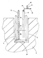
- a geothermal probe 6 is introduced in the borehole 4 .
- a heat transfer medium such as water flow.
- a suspension 24 can be pressed into the borehole 4.
- the level tube 10th is also the level tube 10th
- the outflow opening 12 is not located directly at the upper end of the level tube 10, but at the end of a connecting line 14.
- a mass flow meter 16 is arranged, which determines the volumes of air flowing through the connecting line 14. The measured values determined by the mass flow meter 16 are transmitted to the computer 18 connected thereto. If the suspension 24 is pressed into the borehole 4, the water level 22 of the water 22 located in the borehole 4 rises. If there is no water 22 in the borehole, only the level of the suspension 24 increases during a proper grouting process, but flows in the same way into the level pipe 10 as the water 22.
- the level pipe 10 Since the level pipe 10 is open at the bottom, it changes a change in the level 20 in the well 4 and the level of the water level 22 in the well 22 or the suspension 24.
- the standing on the water column 26 is at a change in the level of the water 22 or the suspension 24 in the well 10 is also moved, and the movement is detected and measured by the mass flow meter 16.
Landscapes
- Physics & Mathematics (AREA)
- Fluid Mechanics (AREA)
- General Physics & Mathematics (AREA)
- Engineering & Computer Science (AREA)
- Signal Processing (AREA)
- Thermal Sciences (AREA)
- Measurement Of Levels Of Liquids Or Fluent Solid Materials (AREA)
Applications Claiming Priority (1)
| Application Number | Priority Date | Filing Date | Title |
|---|---|---|---|
| DE102012016196.4A DE102012016196A1 (de) | 2012-08-16 | 2012-08-16 | Pegelrohr und Verfahren zur Messung des Wasserstands in einem Bohrloch |
Publications (2)
| Publication Number | Publication Date |
|---|---|
| EP2698613A2 true EP2698613A2 (fr) | 2014-02-19 |
| EP2698613A3 EP2698613A3 (fr) | 2018-01-24 |
Family
ID=48793858
Family Applications (1)
| Application Number | Title | Priority Date | Filing Date |
|---|---|---|---|
| EP13003515.7A Withdrawn EP2698613A3 (fr) | 2012-08-16 | 2013-07-11 | Tuyau de niveau et procédé de mesure d'un niveau d'eau dans un trou de forage |
Country Status (2)
| Country | Link |
|---|---|
| EP (1) | EP2698613A3 (fr) |
| DE (1) | DE102012016196A1 (fr) |
Cited By (2)
| Publication number | Priority date | Publication date | Assignee | Title |
|---|---|---|---|---|
| CN108287006A (zh) * | 2018-01-15 | 2018-07-17 | 中国南方电网有限责任公司超高压输电公司广州局 | 基于温度补偿和最小二乘法的阀冷系统轻微渗漏监测方法 |
| CN114810573A (zh) * | 2022-04-29 | 2022-07-29 | 扬州大学 | 一种用于水泵吸气率测定装置 |
Family Cites Families (5)
| Publication number | Priority date | Publication date | Assignee | Title |
|---|---|---|---|---|
| GB2033582B (en) * | 1978-10-31 | 1983-05-11 | Dart Ausschank Rat Tech | Liquid metering method and device |
| RU2104395C1 (ru) * | 1996-02-28 | 1998-02-10 | Валерий Иванович Шмелев | Способ определения уровня в трубах |
| US6952963B2 (en) * | 2003-05-23 | 2005-10-11 | Gambro Dasco S.P.A. | Method for detecting a liquid level in a container in a circuit and a dialysis machine for actuating the method |
| JP2008039770A (ja) * | 2006-07-10 | 2008-02-21 | Mitsuo Ebisawa | 物体検出方法及び物体検出装置 |
| JP2009235666A (ja) * | 2008-03-25 | 2009-10-15 | Takenaka Komuten Co Ltd | 杭形状特定装置及び杭形状特定プログラム |
-
2012
- 2012-08-16 DE DE102012016196.4A patent/DE102012016196A1/de not_active Withdrawn
-
2013
- 2013-07-11 EP EP13003515.7A patent/EP2698613A3/fr not_active Withdrawn
Non-Patent Citations (1)
| Title |
|---|
| None |
Cited By (3)
| Publication number | Priority date | Publication date | Assignee | Title |
|---|---|---|---|---|
| CN108287006A (zh) * | 2018-01-15 | 2018-07-17 | 中国南方电网有限责任公司超高压输电公司广州局 | 基于温度补偿和最小二乘法的阀冷系统轻微渗漏监测方法 |
| CN114810573A (zh) * | 2022-04-29 | 2022-07-29 | 扬州大学 | 一种用于水泵吸气率测定装置 |
| CN114810573B (zh) * | 2022-04-29 | 2023-07-21 | 扬州大学 | 一种用于水泵吸气率测定装置 |
Also Published As
| Publication number | Publication date |
|---|---|
| EP2698613A3 (fr) | 2018-01-24 |
| DE102012016196A1 (de) | 2014-02-20 |
Similar Documents
| Publication | Publication Date | Title |
|---|---|---|
| CN105136638B (zh) | 尾矿坝渗流场相似模拟试验系统 | |
| CN203096683U (zh) | 一种堤防工程渗透破坏发展过程的模型试验装置 | |
| CN103150871A (zh) | 利用地下水位与位移实时监测的滑坡预测方法 | |
| CN102483342A (zh) | 一种确定地面标高的方法和土壤湿度感测器 | |
| CN108196006A (zh) | 一种关于隧道突水防突层厚度的试验装置及方法 | |
| DE112023001795T5 (de) | Vorrichtung zur Messung der desorbierten Gasmenge und Messverfahren | |
| DE102012016196A1 (de) | Pegelrohr und Verfahren zur Messung des Wasserstands in einem Bohrloch | |
| CN106018239A (zh) | 一种测量现场不同深度地层处渗透系数的方法及其装置 | |
| DE102004026381B3 (de) | Verfahren und Vorrichtung zur Messung der Temperatur oder anderen Größen in einer U-förmigen Erdwärmesonde sowie Ausspülanordnung dafür | |
| CN207408280U (zh) | 一种用于覆盖型岩溶区塌陷的土体渗透变形试验装置 | |
| CN105259088A (zh) | 一种用于快速确定非饱和土渗透性函数的方法及装置 | |
| CN203821294U (zh) | 一种模拟水库土坝渗流破坏发展过程的模型试验装置 | |
| CN113203670A (zh) | 一种土石坝心墙土层渗透系数逐层叠加反演方法 | |
| EP3253947B1 (fr) | Procédé et dispositif pour faire fonctionner un transport dans un trou de forage | |
| CN205898625U (zh) | 一种测量现场不同深度地层处渗透系数的装置 | |
| DE102011113541A1 (de) | Messvorrichtung für Wasserzähler und Verfahren zum Betreiben einer batteriebetriebenen Messvorrichtung | |
| CN106198347B (zh) | 岩石渗水率自动测试系统及测试方法 | |
| CN103808448B (zh) | 一种流体渗流环境中压力传导时间的测量方法 | |
| CN114965208B (zh) | 一种原位测量河床含水层渗透系数的方法和装置 | |
| CN203719818U (zh) | 一种流体渗流环境中压力传导时间的测量装置 | |
| EP4001170B1 (fr) | Dispositif de détermination du niveau de remplissage d'un liquide dans un récipient | |
| EP1447329A1 (fr) | Procédé et dispositif pour la distribution de produits fluides | |
| CN207317861U (zh) | 一种灌浆记录系统 | |
| CN116046634A (zh) | 测量土体非饱和渗透特性的装置及方法 | |
| CN207557060U (zh) | 一种研究复杂水流条件下管涌发展的试验装置 |
Legal Events
| Date | Code | Title | Description |
|---|---|---|---|
| AK | Designated contracting states |
Kind code of ref document: A2 Designated state(s): AL AT BE BG CH CY CZ DE DK EE ES FI FR GB GR HR HU IE IS IT LI LT LU LV MC MK MT NL NO PL PT RO RS SE SI SK SM TR |
|
| AX | Request for extension of the european patent |
Extension state: BA ME |
|
| PUAI | Public reference made under article 153(3) epc to a published international application that has entered the european phase |
Free format text: ORIGINAL CODE: 0009012 |
|
| PUAL | Search report despatched |
Free format text: ORIGINAL CODE: 0009013 |
|
| AK | Designated contracting states |
Kind code of ref document: A3 Designated state(s): AL AT BE BG CH CY CZ DE DK EE ES FI FR GB GR HR HU IE IS IT LI LT LU LV MC MK MT NL NO PL PT RO RS SE SI SK SM TR |
|
| AX | Request for extension of the european patent |
Extension state: BA ME |
|
| RIC1 | Information provided on ipc code assigned before grant |
Ipc: G01F 23/22 20060101ALI20171219BHEP Ipc: G01F 23/00 20060101AFI20171219BHEP |
|
| STAA | Information on the status of an ep patent application or granted ep patent |
Free format text: STATUS: THE APPLICATION HAS BEEN PUBLISHED |
|
| STAA | Information on the status of an ep patent application or granted ep patent |
Free format text: STATUS: THE APPLICATION IS DEEMED TO BE WITHDRAWN |
|
| 18D | Application deemed to be withdrawn |
Effective date: 20180725 |