EP2698459A1 - Two-layer weave for non-woven fabric - Google Patents
Two-layer weave for non-woven fabric Download PDFInfo
- Publication number
- EP2698459A1 EP2698459A1 EP12771901.1A EP12771901A EP2698459A1 EP 2698459 A1 EP2698459 A1 EP 2698459A1 EP 12771901 A EP12771901 A EP 12771901A EP 2698459 A1 EP2698459 A1 EP 2698459A1
- Authority
- EP
- European Patent Office
- Prior art keywords
- surface side
- fabric
- weft
- binding
- warp
- Prior art date
- Legal status (The legal status is an assumption and is not a legal conclusion. Google has not performed a legal analysis and makes no representation as to the accuracy of the status listed.)
- Granted
Links
- 239000004745 nonwoven fabric Substances 0.000 title abstract 4
- 239000004744 fabric Substances 0.000 claims abstract description 154
- 239000004033 plastic Substances 0.000 claims description 34
- 229920003023 plastic Polymers 0.000 claims description 34
- YCKRFDGAMUMZLT-UHFFFAOYSA-N Fluorine atom Chemical compound [F] YCKRFDGAMUMZLT-UHFFFAOYSA-N 0.000 claims description 29
- 229910052731 fluorine Inorganic materials 0.000 claims description 29
- 239000011737 fluorine Substances 0.000 claims description 29
- 229920001577 copolymer Polymers 0.000 claims description 7
- BFKJFAAPBSQJPD-UHFFFAOYSA-N tetrafluoroethene Chemical group FC(F)=C(F)F BFKJFAAPBSQJPD-UHFFFAOYSA-N 0.000 claims description 5
- VGGSQFUCUMXWEO-UHFFFAOYSA-N Ethene Chemical compound C=C VGGSQFUCUMXWEO-UHFFFAOYSA-N 0.000 claims description 4
- 239000005977 Ethylene Substances 0.000 claims description 4
- 230000000694 effects Effects 0.000 abstract description 17
- 238000004519 manufacturing process Methods 0.000 abstract description 10
- 239000000835 fiber Substances 0.000 abstract description 9
- 230000003373 anti-fouling effect Effects 0.000 abstract 1
- 230000007774 longterm Effects 0.000 abstract 1
- 238000000034 method Methods 0.000 description 12
- 239000000463 material Substances 0.000 description 9
- -1 ethylene- tetrafluoroethylene Chemical group 0.000 description 6
- XUIMIQQOPSSXEZ-UHFFFAOYSA-N Silicon Chemical compound [Si] XUIMIQQOPSSXEZ-UHFFFAOYSA-N 0.000 description 3
- 239000000853 adhesive Substances 0.000 description 3
- 230000001070 adhesive effect Effects 0.000 description 3
- 239000004566 building material Substances 0.000 description 3
- 238000005516 engineering process Methods 0.000 description 3
- 238000001914 filtration Methods 0.000 description 3
- 229920000139 polyethylene terephthalate Polymers 0.000 description 3
- 239000005020 polyethylene terephthalate Substances 0.000 description 3
- 229920001343 polytetrafluoroethylene Polymers 0.000 description 3
- 239000004810 polytetrafluoroethylene Substances 0.000 description 3
- 239000010703 silicon Substances 0.000 description 3
- 229910052710 silicon Inorganic materials 0.000 description 3
- 239000002033 PVDF binder Substances 0.000 description 2
- 239000002131 composite material Substances 0.000 description 2
- 239000006185 dispersion Substances 0.000 description 2
- 238000005188 flotation Methods 0.000 description 2
- 239000000203 mixture Substances 0.000 description 2
- 229920002981 polyvinylidene fluoride Polymers 0.000 description 2
- XLYOFNOQVPJJNP-UHFFFAOYSA-N water Substances O XLYOFNOQVPJJNP-UHFFFAOYSA-N 0.000 description 2
- JMGNVALALWCTLC-UHFFFAOYSA-N 1-fluoro-2-(2-fluoroethenoxy)ethene Chemical compound FC=COC=CF JMGNVALALWCTLC-UHFFFAOYSA-N 0.000 description 1
- 229920001780 ECTFE Polymers 0.000 description 1
- 239000004593 Epoxy Substances 0.000 description 1
- OFOBLEOULBTSOW-UHFFFAOYSA-N Malonic acid Chemical compound OC(=O)CC(O)=O OFOBLEOULBTSOW-UHFFFAOYSA-N 0.000 description 1
- 239000004952 Polyamide Substances 0.000 description 1
- 239000004734 Polyphenylene sulfide Substances 0.000 description 1
- 239000004743 Polypropylene Substances 0.000 description 1
- 235000019892 Stellar Nutrition 0.000 description 1
- 239000004760 aramid Substances 0.000 description 1
- 229920003235 aromatic polyamide Polymers 0.000 description 1
- 125000003118 aryl group Chemical group 0.000 description 1
- UUAGAQFQZIEFAH-UHFFFAOYSA-N chlorotrifluoroethylene Chemical group FC(F)=C(F)Cl UUAGAQFQZIEFAH-UHFFFAOYSA-N 0.000 description 1
- 238000002788 crimping Methods 0.000 description 1
- 230000003247 decreasing effect Effects 0.000 description 1
- 230000002708 enhancing effect Effects 0.000 description 1
- 229920000840 ethylene tetrafluoroethylene copolymer Polymers 0.000 description 1
- 239000012467 final product Substances 0.000 description 1
- 229920002313 fluoropolymer Polymers 0.000 description 1
- 239000004811 fluoropolymer Substances 0.000 description 1
- HCDGVLDPFQMKDK-UHFFFAOYSA-N hexafluoropropylene Chemical group FC(F)=C(F)C(F)(F)F HCDGVLDPFQMKDK-UHFFFAOYSA-N 0.000 description 1
- 238000002156 mixing Methods 0.000 description 1
- 230000000704 physical effect Effects 0.000 description 1
- 239000000049 pigment Substances 0.000 description 1
- 239000002985 plastic film Substances 0.000 description 1
- 229920006255 plastic film Polymers 0.000 description 1
- 229920001643 poly(ether ketone) Polymers 0.000 description 1
- 229920003207 poly(ethylene-2,6-naphthalate) Polymers 0.000 description 1
- 229920002647 polyamide Polymers 0.000 description 1
- 229920000728 polyester Polymers 0.000 description 1
- 239000011112 polyethylene naphthalate Substances 0.000 description 1
- 229920002959 polymer blend Polymers 0.000 description 1
- 229920000069 polyphenylene sulfide Polymers 0.000 description 1
- 229920001155 polypropylene Polymers 0.000 description 1
- 239000000047 product Substances 0.000 description 1
- 239000007787 solid Substances 0.000 description 1
- 229920002994 synthetic fiber Polymers 0.000 description 1
- 239000012209 synthetic fiber Substances 0.000 description 1
Images


Classifications
-
- B—PERFORMING OPERATIONS; TRANSPORTING
- B32—LAYERED PRODUCTS
- B32B—LAYERED PRODUCTS, i.e. PRODUCTS BUILT-UP OF STRATA OF FLAT OR NON-FLAT, e.g. CELLULAR OR HONEYCOMB, FORM
- B32B5/00—Layered products characterised by the non- homogeneity or physical structure, i.e. comprising a fibrous, filamentary, particulate or foam layer; Layered products characterised by having a layer differing constitutionally or physically in different parts
- B32B5/02—Layered products characterised by the non- homogeneity or physical structure, i.e. comprising a fibrous, filamentary, particulate or foam layer; Layered products characterised by having a layer differing constitutionally or physically in different parts characterised by structural features of a fibrous or filamentary layer
- B32B5/06—Layered products characterised by the non- homogeneity or physical structure, i.e. comprising a fibrous, filamentary, particulate or foam layer; Layered products characterised by having a layer differing constitutionally or physically in different parts characterised by structural features of a fibrous or filamentary layer characterised by a fibrous or filamentary layer mechanically connected, e.g. by needling to another layer, e.g. of fibres, of paper
-
- B—PERFORMING OPERATIONS; TRANSPORTING
- B32—LAYERED PRODUCTS
- B32B—LAYERED PRODUCTS, i.e. PRODUCTS BUILT-UP OF STRATA OF FLAT OR NON-FLAT, e.g. CELLULAR OR HONEYCOMB, FORM
- B32B5/00—Layered products characterised by the non- homogeneity or physical structure, i.e. comprising a fibrous, filamentary, particulate or foam layer; Layered products characterised by having a layer differing constitutionally or physically in different parts
- B32B5/02—Layered products characterised by the non- homogeneity or physical structure, i.e. comprising a fibrous, filamentary, particulate or foam layer; Layered products characterised by having a layer differing constitutionally or physically in different parts characterised by structural features of a fibrous or filamentary layer
- B32B5/024—Woven fabric
-
- B—PERFORMING OPERATIONS; TRANSPORTING
- B32—LAYERED PRODUCTS
- B32B—LAYERED PRODUCTS, i.e. PRODUCTS BUILT-UP OF STRATA OF FLAT OR NON-FLAT, e.g. CELLULAR OR HONEYCOMB, FORM
- B32B5/00—Layered products characterised by the non- homogeneity or physical structure, i.e. comprising a fibrous, filamentary, particulate or foam layer; Layered products characterised by having a layer differing constitutionally or physically in different parts
- B32B5/22—Layered products characterised by the non- homogeneity or physical structure, i.e. comprising a fibrous, filamentary, particulate or foam layer; Layered products characterised by having a layer differing constitutionally or physically in different parts characterised by the presence of two or more layers which are next to each other and are fibrous, filamentary, formed of particles or foamed
- B32B5/24—Layered products characterised by the non- homogeneity or physical structure, i.e. comprising a fibrous, filamentary, particulate or foam layer; Layered products characterised by having a layer differing constitutionally or physically in different parts characterised by the presence of two or more layers which are next to each other and are fibrous, filamentary, formed of particles or foamed one layer being a fibrous or filamentary layer
- B32B5/26—Layered products characterised by the non- homogeneity or physical structure, i.e. comprising a fibrous, filamentary, particulate or foam layer; Layered products characterised by having a layer differing constitutionally or physically in different parts characterised by the presence of two or more layers which are next to each other and are fibrous, filamentary, formed of particles or foamed one layer being a fibrous or filamentary layer another layer next to it also being fibrous or filamentary
-
- D—TEXTILES; PAPER
- D03—WEAVING
- D03D—WOVEN FABRICS; METHODS OF WEAVING; LOOMS
- D03D11/00—Double or multi-ply fabrics not otherwise provided for
-
- D—TEXTILES; PAPER
- D03—WEAVING
- D03D—WOVEN FABRICS; METHODS OF WEAVING; LOOMS
- D03D15/00—Woven fabrics characterised by the material, structure or properties of the fibres, filaments, yarns, threads or other warp or weft elements used
- D03D15/20—Woven fabrics characterised by the material, structure or properties of the fibres, filaments, yarns, threads or other warp or weft elements used characterised by the material of the fibres or filaments constituting the yarns or threads
- D03D15/283—Woven fabrics characterised by the material, structure or properties of the fibres, filaments, yarns, threads or other warp or weft elements used characterised by the material of the fibres or filaments constituting the yarns or threads synthetic polymer-based, e.g. polyamide or polyester fibres
-
- Y—GENERAL TAGGING OF NEW TECHNOLOGICAL DEVELOPMENTS; GENERAL TAGGING OF CROSS-SECTIONAL TECHNOLOGIES SPANNING OVER SEVERAL SECTIONS OF THE IPC; TECHNICAL SUBJECTS COVERED BY FORMER USPC CROSS-REFERENCE ART COLLECTIONS [XRACs] AND DIGESTS
- Y10—TECHNICAL SUBJECTS COVERED BY FORMER USPC
- Y10T—TECHNICAL SUBJECTS COVERED BY FORMER US CLASSIFICATION
- Y10T442/00—Fabric [woven, knitted, or nonwoven textile or cloth, etc.]
- Y10T442/30—Woven fabric [i.e., woven strand or strip material]
- Y10T442/3472—Woven fabric including an additional woven fabric layer
- Y10T442/348—Mechanically needled or hydroentangled
Definitions
- the present invention relates to a fabric used for manufacturing unwoven fabric, in particular, relates to an anti-dirt two-layer fabric for unwoven fabric which can keep the anti-dirt effect for a long time.
- an industrial fabric woven by wefts and warps has been used for a transporting or filtering application in a manufacturing process of papers, unwoven fabric, building material, etc..
- Such industrial fabric needs to possess a high rigidity, a good dimension stability, and anti-dirt characteristics, etc. for any applications.
- the high rigidity is required in order to hold and transport an object such as material, flotation material component, etc..
- the high rigidity is essential for the fabric which deals with the heavy material or the flotation material component.
- the dimension stability is needed in order to constantly run the fabric in a stable manner.
- the anti-dirt characteristics is important for efficient filtering and transportation.
- the anti-dirt characteristics of the fabric is important for an air raid process which is one of the processes of manufacturing unwoven fabric, since it is closely associated with the problem of adhesion of fibers.
- the air raid process is the process in which pulp sheet and synthetic fibers of short fibers are dispersed in air to be formed on an wire.
- a main process of binding fibers is an adhesive type in which the fibers are fused to be bound by suing adhesive fibers, etc..
- the adhesive fibers are fused with the fabric on the wire.
- a rate of an amount of polymer blend with a high rigidity such as PET, etc. only needs to be increased in order to improve the rigidity
- a rate of an amount of fluorine plastic only needs to be increased in order to improve the anti-dirt characteristics.
- the composition of the yarn for attaining the rigidity is not compatible with that for attaining the anti-dirt characteristics, so that it was pointed out that it was technically difficult to sufficiently obtain both of the rigidity and the anti-dirt characteristics required for the industrial fabric only by the composition of the yarn constituting the fabric.
- the object of the present invention is to provide an anti-dirt two-layer fabric for unwoven fabric which is capable of keeping the anti-dirt effect even if its surface gets worn due to its use for a long time in a process of manufacturing the unwoven fabric, while at the same time, enhancing an anti-adhesion effect by adopting fluorine plastic and attaining characteristics required for the fabric for unwoven fabric such as rigidity, etc.,
- the present inventor adopted the following two-layer fabric for unwoven fabric which attains high rigidity and extension, and keeps the anti-dirt effect for a long time.
- anti-dirt two-layer fabric for unwoven fabric of the present invention anti-adhesion effect by which fibers, etc. is prevented from being adhered thereto is enhanced by adopting fluorine plastic and characteristics required for the fabric for unwoven fabric such as rigidity is attained, while at the same time, the anti-dirt effect is kept even if its surface gets worn due to its use for a long time in a process of manufacturing the unwoven fabric.
- the two-layer fabric for unwoven fabric of the present invention is the one which includes at least one upper surface side fabric constituted by upper surface side warps and upper surface side wefts, at least one lower surface side fabric constituted by lower surface side warps and lower surface side wefts, and binding weft yarns each of which binds the upper surface side fabric and the lower surface side fabric.
- one of the technical features of the present invention is that, in the upper surface side fabric, fluorine plastic is adopted for the upper surface side warps and the upper surface side wefts.
- the upper surface side fabric is constituted only by fluorine plastic
- the lower surface side warps and the lower surface side wefts are constituted by general yarns.
- the binding weft yarns are adapted to be woven so as to effect an inner binding in a case where they are bound by the upper surface side warps.
- the inner binding is defined to arrange the binding weft yarns so as not to appear on the surface of the fabric.
- the two-layer fabric for unwoven fabric adopts an on-stack structure in which the upper and lower surface side warps, and the upper and lower surface side wefts are woven to be arranged in a perpendicular positional relation, respectively.
- a complete structure of the fabric is defined to be the minimum unit to be repeated of the fabric structure.
- the fabric is completed by combining any number of such complete structures in the longitudinal direction and the direction perpendicular to the longitudinal direction.
- a knuckle is a portion of a warp which passes above or below one or a plurality of wefts to protrude from the surface.
- a crimp is a long floating structure which is formed on the surface by the wefts passing above or below one or a plurality of warps.
- the on-stack structure is the one in which upper and lower yarns in the same direction are vertically overlapped with each other.
- the fabric in which yarns made of fluorine plastic are used for surface wefts are publicly known.
- the yarns made of fluorine plastic lack in the durability, the rigidity of the fabric is decreased in a case where all the wefts are constituted by the yarns made of fluorine plastic, whereby it becomes technically difficult to use such a fabric for the process of manufacturing unwoven fabric in a practical basis.
- general yarns have been used for the surface which contacts the unwoven fabric, so that the fabric with sufficient anti-dirt characteristics could not be obtained.
- the present inventor created the two-layer fabric for unwoven fabric which adopts the yarns made of fluorine plastic for the yarns constituting the surface contacting the unwoven fabric to be transported, and adopts the yarns made of fluorine plastic for the upper surface side layer, while the general yarns for the lower surface side layer, in order to attain the characteristics required for the fabric for the unwoven fabric, and is constituted by the upper and lower surface side layers woven by the binding weft yarns.
- the two-layer fabric for unwoven fabric of the present invention is the one which attains the characteristics required for the fabric for the unwoven fabric, while at the same time, uses the yarns made of fluorine plastic.
- the two-layer fabric for unwoven fabric of the present invention is constituted by the upper surface side warps, the upper surface side wefts, the lower surface side warps, the lower surface side wefts, and the binding weft yarns which weave the upper surface side warps and the lower surface side warps.
- the yarns made of fluorine plastic are used for the upper surface side warps and the upper surface side wefts constituting the upper surface side layer. Accordingly, in the present invention, the anti-dirt characteristics of the fabric can be obtained by using the yarns made of fluorine plastic for the yarns at the upper surface side directly contacting the unwoven fabric, while the rigidity and the extension characteristics of the fabric can be secured by using the general yarns for the lower surface side warps and the lower surface side wefts constituting the lower surface side layer.
- binding weft yarns are arranged so as not to appear on the surface of the fabric by the inner binding by which the binding weft yarns and the upper surface side warps are woven with each other at a portion where the upper surface side warps are woven inside the fabric.
- the fabric which attains the characteristics required for the fabric for unwoven fabric can be provided by the fact that the upper surface side layer and the lower surface side layer are woven with each other by the binding weft yarns and all of the surface contacting the unwoven fabric is constituted by the yarns made of fluorine plastic.
- the lower surface side fabric is prevented from being exposed due to the cover of the upper surface side fabric, so that only the upper surface side fabric which enhances the anti-dirt effect contacts the unwoven fabric on the surface of the fabric.
- auxiliary wefts with a diameter smaller than that of the upper side surface side weft may be arranged between the upper surface side wefts. For instance, surface properties can be improved by the fact that the upper surface side wefts and the auxiliary wefts are arranged in an alternate manner.
- the fluorine plastic which is material for the upper surface side warps and the upper surface side wefts of the fabric of the present invention may be preferably composite plastic containing fluorine with high anti-dirt.
- at least one material can be selected from a group of polytetrafluoroethylene (PTFE), copolymer of tetrafluoroethylene and hexafluoropropylene (FEP), copolymer of tetrafluoroethylene and fluoro vinyl ether (PFA), polyvinylidene fluoride (PVDF), copolymer of ethylene and tetrafluoroethylene (ETFE), and copolymer of ethylene and chlorotrifluoroethylene(ECTFE).
- ETFE is suitable for the anti-dirt characteristics and cost.
- the fluorine plastic material water dispersion
- the color of the surface of the fabric can be freely changed by adding various kinds of pigment to the fluorine plastic material (water dispersion) .
- the general yarn used for the lower surface side fabric can be polyester, polyamide, polyphenylene sulfide, polypropylene, aramid, polyether ketone, polyethylene naphthalate, polytetrafluoroethylene, etc.
- the configuration of the yarn includes, in addition to monofilaments, multifilaments, spun yarns, finished yarns subjected to crimping or bulking such as so-called textured yarn, bulky yarn and stretch yarn, and yarns obtained by intertwining them.
- As the cross-section of the yarn not only circular form but also square or short form such as stellar form, or elliptical or hollow form can be used.
- the unwoven fabric needs to have a high rigidity, since it is used with being stretched in the warp direction.
- the configuration of the yarn is preferably the monofilaments.
- the fabric of the present invention can be suitably used under the high tension by adopting monofilaments with a high rigidity as the lower surface side warp.
- the structure in which the upper surface side fabric and the lower surface side fabric are woven with each other by arranging the auxiliary weft at the upper surface side of the binding weft yarn may be adopted.
- the auxiliary weft cooperates with the binding weft yarn to form the on-stack structure to improve the surface smoothness.
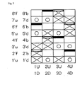
- the design view corresponds to the complete structure of the fabric defining the minimum unit to be repeated of the fabric structure.
- the fabric recited in the claims corresponds to this complete structure.
- the final product is completed by combining any number of such complete structures in the longitudinal direction and the direction perpendicular to the longitudinal direction.
- the warp is indicated by a reference number such as 1,2,3 .
- the upper and lower warps are indicated by the reference number to which U and D are attached, respectively.
- the weft is indicated by a reference number such as 1',2' ,3' .
- the upper surface side weft and the lower surface side weft are indicated by the reference number to which u and d are attached, respectively, such as 1'u, 2' d, etc..
- the binding weft yarn and the auxiliary weft are indicated by the reference number to which b and f are attached, respectively, such as 1'u, 1'd, 2'b, 2' f, etc.
- a symbol “ ⁇ ” indicates that the upper surface side warp is arranged above the upper surface side weft or the auxiliary weft
- a symbol “ ⁇ ” indicates that the lower surface side warp is arranged below the lower surface side weft
- a solid square symbol “ ⁇ ” indicates that the binding weft yarn is arranged above the upper surface side warps
- an open square symbol “ ⁇ ” indicates that the binding weft yarn is arranged below the lower surface side warps.
- the symbols “ ⁇ ” and “ ⁇ ” are depicted as an elongate rectangle at the upper portion of the grid in each of the design views.
- Fig.1 is a design view showing a complete design of the two-layer fabric for unwoven fabric according to the first embodiment.
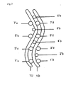
- Fig.2 is a cross section view taken along the warp 1 in Fig.1
- the two-layer fabric for unwoven fabric of the first embodiment in Fig.1 constitute a two-layer fabric including the upper surface side warp U, the lower surface side warp D, the upper surface side weft u, the lower surface side weft d, and the binding weft yarn b.
- a knuckle at the upper surface side is formed by the fact the upper surface side warp 1U passes above the upper surface side weft 1'u, and passes above the upper surface side weft 2'u and the binding weft yarn 4'b. Then, the upper surface side warp 1U passes below the upper surface side weft 5'u and passes below the binding weft yarn 6'b and the upper surface side weft 7'u and passes above the binding weft yarn 8'b.
- a knuckle at the lower surface side is formed by the fact the lower surface side warp 1D passes above the lower surface side weft 1'd, and passes above the binding weft yarn 2'b and the lower surface side weft 3'd, and then, passes below the binding weft yarn 4'b, the lower surface side weft 5'd, the lower surface side weft 7'd and the binding weft yarn 8'b.
- the binding weft yarn 6'b passes above the upper surface side warp 1U to weave the upper surface side layer, and then, passes between the upper surface side warp 2U and the lower surface side warp 2D and between the upper surface side warp 3U and the lower surface side warp 3D and passes below the lower surface side warp 4D to bind the upper and lower surface side layers.
- the binding weft yarn 6'b is shown to be located inside the upper surface side knuckle forming the upper surface side layer and the upper surface side wefts 5'u and 7'u at a portion where the binding weft yarn 6'b weaves the upper surface side layer.
- the inner binding is formed at the binding weft yarn 6'b and the upper surface side warp 1U, so that the upper surface side layer is woven without the binding weft yarn being exposed to the surface.
- the yarns constituting the lower surface side fabric are prevented from directly contacting the unwoven fabric to be transported by the fabric, due to the on-stack structure of the warps and the wefts.
- the two-layer anti-dirt fabric for unwoven fabric in the first embodiment enhances the anti-adhesion effect by which the fibers are not adhered to the fabric, while attains the physical properties required for the fabric such as the rigidity by adopting the fluorine plastic, and keeps the anti-dirt effect even when the surface of the fabric gets worn out.
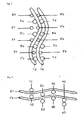
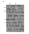
- Fig.3 is a design view showing a complete design of the second embodiment.
- Fig.4 is a cross section view taken from the warp 1 in Fig.3 .
- Fig.5 is a cross section view taken from the weft 2' in Fig.3 .
- Fig.6 is a plane view of the upper surface side in Fig.3 .
- the lower surface side yarns are indicated by a diagonal line in order to show the upper surface side warp constituted by the fluorine plastic and the lower surface side yarns constituted by the general yarns under the upper surface side weft.
- Fig.7 is a photograph of the surface of the fabric of the second embodiment.
- the two-layer fabric for unwoven fabric of the second embodiment in Fig.3 constitute a two-layer fabric including the upper surface side warp U, the lower surface side warp D, the upper surface side weft u, the lower surface side weft d, and the binding weft yarn b.
- a knuckle at the upper surface side is formed by the fact the upper surface side warp 1U passes above the upper surface side weft 1'u, and passes above the binding weft yarn 2'f and the upper surface side weft 3'u. Then, the upper surface side warp 1U passes between the binding weft yarn 4'f and the binding weft yarn 4'b, and passes below the upper surface side weft 5'u, the binding weft yarn 6'b and the upper surface side weft 7'u, and passes between the binding weft yarn 8'f and the binding weft yarn 8'b.
- a knuckle at the lower surface side is formed by the fact the lower surface side warp 1D passes above the lower surface side weft 1'd, and passes above the binding weft yarn 2'b and the lower surface side weft 3'd, and then, passes below the binding weft yarn 4'b, the lower surface side weft 5'd, the binding weft yarn 6'b, the lower surface side weft 7'd and the binding weft yarn 8'b.
- the binding weft yarn 6'f is arranged between the upper surface side wefts.
- the surface properties are improved by the fact that the binding weft yarn 6'f is arranged at the upper surface side of the binding weft yarn 6'b, and adopts the on-stack structure with the binding weft yarn 6'b.
Abstract
Description
- The present invention relates to a fabric used for manufacturing unwoven fabric, in particular, relates to an anti-dirt two-layer fabric for unwoven fabric which can keep the anti-dirt effect for a long time.
- Conventionally, an industrial fabric woven by wefts and warps has been used for a transporting or filtering application in a manufacturing process of papers, unwoven fabric, building material, etc.. Such industrial fabric needs to possess a high rigidity, a good dimension stability, and anti-dirt characteristics, etc. for any applications.
- More specifically, the high rigidity is required in order to hold and transport an object such as material, flotation material component, etc.. In particular, in case of the manufacturing process of the building material, or the filtering process, the high rigidity is essential for the fabric which deals with the heavy material or the flotation material component. Further, the dimension stability is needed in order to constantly run the fabric in a stable manner. In addition, in order to always supply products of papers, unwoven fabric, or the building material with stable quality, the anti-dirt characteristics is important for efficient filtering and transportation.
- In particular, the anti-dirt characteristics of the fabric is important for an air raid process which is one of the processes of manufacturing unwoven fabric, since it is closely associated with the problem of adhesion of fibers. Here, the air raid process is the process in which pulp sheet and synthetic fibers of short fibers are dispersed in air to be formed on an wire. A main process of binding fibers is an adhesive type in which the fibers are fused to be bound by suing adhesive fibers, etc.. However, in the air raid process using the adhesion type, it was pointed out that the adhesive fibers are fused with the fabric on the wire.
- Therefore, recently, yarns and plastic material with a view to attain the anti-dirt effect have been developed, in particular. For instance, a technology in which the yarn constituted by blending fluoro polymer such as copolymer of ethylene- tetrafluoroethylene (referred to as " ETFE " hereinafter) and dicarboxylic acid in aromatic series such as polyethylene terephthalate (referred to as "PET" hereinafter) (refer to Patent Publication 1).
- Nowadays, the above fluorine plastic with a excellent anti-dirt characteristic has been widely used for the anti-dirt application.
- However, high rigidity such as predetermined breaking strength and predetermined tension strength was required in addition to the anti-dirt effect, in order to use the fabric for unwoven fabric. Since the fabric woven only by the above fluorine plastic such as ETFE exhibits a poor rigidity, it was technically difficult to obtain a sufficient strength as the fabric used in the process of manufacturing the unwoven fabric.
- Here, a rate of an amount of polymer blend with a high rigidity such as PET, etc. only needs to be increased in order to improve the rigidity, while on the other hand, a rate of an amount of fluorine plastic only needs to be increased in order to improve the anti-dirt characteristics.
- Accordingly, the composition of the yarn for attaining the rigidity is not compatible with that for attaining the anti-dirt characteristics, so that it was pointed out that it was technically difficult to sufficiently obtain both of the rigidity and the anti-dirt characteristics required for the industrial fabric only by the composition of the yarn constituting the fabric.
- Such being the case, in view of fully obtaining both of the rigidity and the anti-dirt characteristics required for the industrial fabric, the technology related to the fabric for web the surface of which is coated with at least two kinds of plastics among fluorine plastic, silicon plastic, and epoxy plastic was disclosed (refer to Patent Publication 2). In addition, the technology related to an anti-dirt industrial fabric which uses composite yarns forming a film made of silicon or fluorine plastic was developed(refer to Patent Publication 3).
- However, if these fabrics are used for the process of manufacturing the unwoven fabric, as the term for use becomes long, a risk of the plastic film coming away due to the wear of these fabrics arises, so that it is presumed that it becomes technically difficult to keep the anti-dirt effect for a long time.
- Patent Publication 1: Japanese Patent Laid-open Publication
HEI11-189947 - Patent Publication 2: Japanese Patent Laid-open Publication
SHO57-171790 - Patent Publication 3: Japanese Patent Laid-open Publication
2008-133570 - The object of the present invention is to provide an anti-dirt two-layer fabric for unwoven fabric which is capable of keeping the anti-dirt effect even if its surface gets worn due to its use for a long time in a process of manufacturing the unwoven fabric, while at the same time, enhancing an anti-adhesion effect by adopting fluorine plastic and attaining characteristics required for the fabric for unwoven fabric such as rigidity, etc.,
- In order to solve the above technical problems, the present inventor adopted the following two-layer fabric for unwoven fabric which attains high rigidity and extension, and keeps the anti-dirt effect for a long time.
- 1. A two-layer fabric for unwoven fabric comprises an upper surface side fabric at least constituted by an upper surface side warp and an upper surface side weft, and a lower surface side fabric at least constituted by a lower surface side warp and a lower surface side weft, said upper surface side fabric and said lower surface side fabric are bound by weft binding yarns, said weft binding yarns are woven so as to be arranged in an inner binding condition, said upper surface side warp and said upper surface side weft are made of fluorine plastic.
- 2. The two-layer fabric for unwoven fabric according to
claim 1, wherein a pair of said upper surface side warps and a pair of said upper surface side wefts are woven so as to be arranged to be perpendicular to the surface of the fabric to form an on-stack structure. - 3. The two-layer fabric for unwoven fabric according to
claim 1 or claim 2, wherein an auxiliary weft are arranged at the upper surface side of said weft binding yarns so as to weave said upper surface side fabric and said lower surface side fabric. - 4. The two-layer fabric for unwoven fabric according to any of
claims 1 to 3, wherein said fluorine plastic is copolymer of ethylene and tetrafluoroethylene (ETFE). - 5. The two-layer fabric for unwoven fabric according to any of
claims 1 to 4, wherein said lower surface side warp and said lower surface side weft and said weft binding yarns are formed by general yarn. - According to the anti-dirt two-layer fabric for unwoven fabric of the present invention, anti-adhesion effect by which fibers, etc. is prevented from being adhered thereto is enhanced by adopting fluorine plastic and characteristics required for the fabric for unwoven fabric such as rigidity is attained, while at the same time, the anti-dirt effect is kept even if its surface gets worn due to its use for a long time in a process of manufacturing the unwoven fabric.
- Now, the structure and the effect of the two-layer fabric for unwoven fabric of the present invention will be described below. Embodiments of the two-layer fabric for unwoven fabric of the present invention will be described thereafter with reference to the drawings.
- The two-layer fabric for unwoven fabric of the present invention is the one which includes at least one upper surface side fabric constituted by upper surface side warps and upper surface side wefts, at least one lower surface side fabric constituted by lower surface side warps and lower surface side wefts, and binding weft yarns each of which binds the upper surface side fabric and the lower surface side fabric.
- Here, one of the technical features of the present invention is that, in the upper surface side fabric, fluorine plastic is adopted for the upper surface side warps and the upper surface side wefts. As such, the upper surface side fabric is constituted only by fluorine plastic, while, in the lower surface side fabric, the lower surface side warps and the lower surface side wefts are constituted by general yarns. In addition, the binding weft yarns are adapted to be woven so as to effect an inner binding in a case where they are bound by the upper surface side warps. Here, the inner binding is defined to arrange the binding weft yarns so as not to appear on the surface of the fabric. Another of the technical features of the present invention is that the two-layer fabric for unwoven fabric adopts an on-stack structure in which the upper and lower surface side warps, and the upper and lower surface side wefts are woven to be arranged in a perpendicular positional relation, respectively.
- In the present invention, a complete structure of the fabric is defined to be the minimum unit to be repeated of the fabric structure. The fabric is completed by combining any number of such complete structures in the longitudinal direction and the direction perpendicular to the longitudinal direction.
- In the present invention, a knuckle is a portion of a warp which passes above or below one or a plurality of wefts to protrude from the surface. In addition, a crimp is a long floating structure which is formed on the surface by the wefts passing above or below one or a plurality of warps.
- Further, the on-stack structure is the one in which upper and lower yarns in the same direction are vertically overlapped with each other.
- Conventionally, in order to improve the anti-dirt effect, the fabric in which yarns made of fluorine plastic are used for surface wefts are publicly known. However, since the yarns made of fluorine plastic lack in the durability, the rigidity of the fabric is decreased in a case where all the wefts are constituted by the yarns made of fluorine plastic, whereby it becomes technically difficult to use such a fabric for the process of manufacturing unwoven fabric in a practical basis. In addition, it was not feasible to adopt the yarns made of fluorine plastic for the warps which largely influence on the extension characteristics of the fabric. Such being the case, general yarns have been used for the surface which contacts the unwoven fabric, so that the fabric with sufficient anti-dirt characteristics could not be obtained.
- Accordingly, the present inventor created the two-layer fabric for unwoven fabric which adopts the yarns made of fluorine plastic for the yarns constituting the surface contacting the unwoven fabric to be transported, and adopts the yarns made of fluorine plastic for the upper surface side layer, while the general yarns for the lower surface side layer, in order to attain the characteristics required for the fabric for the unwoven fabric, and is constituted by the upper and lower surface side layers woven by the binding weft yarns.
- The two-layer fabric for unwoven fabric of the present invention is the one which attains the characteristics required for the fabric for the unwoven fabric, while at the same time, uses the yarns made of fluorine plastic. The two-layer fabric for unwoven fabric of the present invention is constituted by the upper surface side warps, the upper surface side wefts, the lower surface side warps, the lower surface side wefts, and the binding weft yarns which weave the upper surface side warps and the lower surface side warps.
- The yarns made of fluorine plastic are used for the upper surface side warps and the upper surface side wefts constituting the upper surface side layer. Accordingly, in the present invention, the anti-dirt characteristics of the fabric can be obtained by using the yarns made of fluorine plastic for the yarns at the upper surface side directly contacting the unwoven fabric, while the rigidity and the extension characteristics of the fabric can be secured by using the general yarns for the lower surface side warps and the lower surface side wefts constituting the lower surface side layer.
- In addition, the binding weft yarns are arranged so as not to appear on the surface of the fabric by the inner binding by which the binding weft yarns and the upper surface side warps are woven with each other at a portion where the upper surface side warps are woven inside the fabric.
- The fabric which attains the characteristics required for the fabric for unwoven fabric can be provided by the fact that the upper surface side layer and the lower surface side layer are woven with each other by the binding weft yarns and all of the surface contacting the unwoven fabric is constituted by the yarns made of fluorine plastic.
- In addition, by adopting the on-stack structure, the lower surface side fabric is prevented from being exposed due to the cover of the upper surface side fabric, so that only the upper surface side fabric which enhances the anti-dirt effect contacts the unwoven fabric on the surface of the fabric.
- Further, in the fabric of the present invention, auxiliary wefts with a diameter smaller than that of the upper side surface side weft may be arranged between the upper surface side wefts. For instance, surface properties can be improved by the fact that the upper surface side wefts and the auxiliary wefts are arranged in an alternate manner.
- The fluorine plastic which is material for the upper surface side warps and the upper surface side wefts of the fabric of the present invention may be preferably composite plastic containing fluorine with high anti-dirt. For instance, at least one material can be selected from a group of polytetrafluoroethylene (PTFE), copolymer of tetrafluoroethylene and hexafluoropropylene (FEP), copolymer of tetrafluoroethylene and fluoro vinyl ether (PFA), polyvinylidene fluoride (PVDF), copolymer of ethylene and tetrafluoroethylene (ETFE), and copolymer of ethylene and chlorotrifluoroethylene(ECTFE). In particular, ETFE is suitable for the anti-dirt characteristics and cost.
- In this connection, it is preferable to impregnate silicon plastic in the fluorine plastic material (water dispersion) in order to improve the flexibility. In addition, the color of the surface of the fabric can be freely changed by adding various kinds of pigment to the fluorine plastic material (water dispersion) .
- The general yarn used for the lower surface side fabric can be polyester, polyamide, polyphenylene sulfide, polypropylene, aramid, polyether ketone, polyethylene naphthalate, polytetrafluoroethylene, etc.
- The configuration of the yarn includes, in addition to monofilaments, multifilaments, spun yarns, finished yarns subjected to crimping or bulking such as so-called textured yarn, bulky yarn and stretch yarn, and yarns obtained by intertwining them. As the cross-section of the yarn, not only circular form but also square or short form such as stellar form, or elliptical or hollow form can be used.
- The unwoven fabric needs to have a high rigidity, since it is used with being stretched in the warp direction. In view of this, the configuration of the yarn is preferably the monofilaments. The fabric of the present invention can be suitably used under the high tension by adopting monofilaments with a high rigidity as the lower surface side warp.
- In addition, the structure in which the upper surface side fabric and the lower surface side fabric are woven with each other by arranging the auxiliary weft at the upper surface side of the binding weft yarn may be adopted.
- Here, the auxiliary weft cooperates with the binding weft yarn to form the on-stack structure to improve the surface smoothness.
- Now, the embodiments of the present invention will be described below with reference to the drawings. Here, the design view corresponds to the complete structure of the fabric defining the minimum unit to be repeated of the fabric structure. The fabric recited in the claims corresponds to this complete structure. The final product is completed by combining any number of such complete structures in the longitudinal direction and the direction perpendicular to the longitudinal direction.
- In each of the design views, the warp is indicated by a reference number such as 1,2,3 ...... The upper and lower warps are indicated by the reference number to which U and D are attached, respectively.
- The weft is indicated by a reference number such as 1',2' ,3' ...... The upper surface side weft and the lower surface side weft are indicated by the reference number to which u and d are attached, respectively, such as 1'u, 2' d, etc.. In addition, the binding weft yarn and the auxiliary weft are indicated by the reference number to which b and f are attached, respectively, such as 1'u, 1'd, 2'b, 2' f, etc.
- In each of the design views, a symbol "×" indicates that the upper surface side warp is arranged above the upper surface side weft or the auxiliary weft, and a symbol "○" indicates that the lower surface side warp is arranged below the lower surface side weft. A solid square symbol "■" indicates that the binding weft yarn is arranged above the upper surface side warps, and an open square symbol "□" indicates that the binding weft yarn is arranged below the lower surface side warps. In this connection, the symbols "■" and "□" are depicted as an elongate rectangle at the upper portion of the grid in each of the design views.
-
Fig.1 is a design view showing a complete design of the two-layer fabric for unwoven fabric according to the first embodiment.Fig.2 is a cross section view taken along thewarp 1 inFig.1 - The two-layer fabric for unwoven fabric of the first embodiment in
Fig.1 constitute a two-layer fabric including the upper surface side warp U, the lower surface side warp D, the upper surface side weft u, the lower surface side weft d, and the binding weft yarn b. - As shown in
Fig.1 , a knuckle at the upper surface side is formed by the fact the uppersurface side warp 1U passes above the upper surface side weft 1'u, and passes above the upper surface side weft 2'u and the binding weft yarn 4'b. Then, the uppersurface side warp 1U passes below the upper surface side weft 5'u and passes below the binding weft yarn 6'b and the upper surface side weft 7'u and passes above the binding weft yarn 8'b. - In addition, a knuckle at the lower surface side is formed by the fact the lower
surface side warp 1D passes above the lowersurface side weft 1'd, and passes above the binding weft yarn 2'b and the lower surface side weft 3'd, and then, passes below the binding weft yarn 4'b, the lower surface side weft 5'd, the lower surface side weft 7'd and the binding weft yarn 8'b. - Here, with respect to the binding weft yarn b, the binding weft yarn 6'b passes above the upper
surface side warp 1U to weave the upper surface side layer, and then, passes between the uppersurface side warp 2U and the lowersurface side warp 2D and between the uppersurface side warp 3U and the lowersurface side warp 3D and passes below the lowersurface side warp 4D to bind the upper and lower surface side layers. - As shown in
Fig.2 , the binding weft yarn 6'b is shown to be located inside the upper surface side knuckle forming the upper surface side layer and the upper surface side wefts 5'u and 7'u at a portion where the binding weft yarn 6'b weaves the upper surface side layer. As such, the inner binding is formed at the binding weft yarn 6'b and the uppersurface side warp 1U, so that the upper surface side layer is woven without the binding weft yarn being exposed to the surface. - In addition, the yarns constituting the lower surface side fabric are prevented from directly contacting the unwoven fabric to be transported by the fabric, due to the on-stack structure of the warps and the wefts.
- By the above configuration, the two-layer anti-dirt fabric for unwoven fabric in the first embodiment enhances the anti-adhesion effect by which the fibers are not adhered to the fabric, while attains the physical properties required for the fabric such as the rigidity by adopting the fluorine plastic, and keeps the anti-dirt effect even when the surface of the fabric gets worn out.
-
Fig.3 is a design view showing a complete design of the second embodiment.Fig.4 is a cross section view taken from thewarp 1 inFig.3 .Fig.5 is a cross section view taken from the weft 2' inFig.3 .Fig.6 is a plane view of the upper surface side inFig.3 . InFig.6 , the lower surface side yarns are indicated by a diagonal line in order to show the upper surface side warp constituted by the fluorine plastic and the lower surface side yarns constituted by the general yarns under the upper surface side weft. In addition, the lower surface side warps and wefts are shown to be thinner than the upper surface side warps and wefts in the above Figs, in order to indicate the overlapped yarns. In fact, the diameters of the lower surface side warps and wefts, and the upper surface side warps and wefts may be appropriately selected.Fig.7 is a photograph of the surface of the fabric of the second embodiment. - As shown in
Fig.3 , the two-layer fabric for unwoven fabric of the second embodiment inFig.3 constitute a two-layer fabric including the upper surface side warp U, the lower surface side warp D, the upper surface side weft u, the lower surface side weft d, and the binding weft yarn b. - As shown in
Fig.3 , a knuckle at the upper surface side is formed by the fact the uppersurface side warp 1U passes above the upper surface side weft 1'u, and passes above the binding weft yarn 2'f and the upper surface side weft 3'u. Then, the uppersurface side warp 1U passes between the binding weft yarn 4'f and the binding weft yarn 4'b, and passes below the upper surface side weft 5'u, the binding weft yarn 6'b and the upper surface side weft 7'u, and passes between the binding weft yarn 8'f and the binding weft yarn 8'b. - In addition, a knuckle at the lower surface side is formed by the fact the lower
surface side warp 1D passes above the lowersurface side weft 1'd, and passes above the binding weft yarn 2'b and the lower surface side weft 3'd, and then, passes below the binding weft yarn 4'b, the lower surface side weft 5'd, the binding weft yarn 6'b, the lower surface side weft 7'd and the binding weft yarn 8'b. - Further, in the fabric of the second embodiment, the binding weft yarn 6'f is arranged between the upper surface side wefts. The surface properties are improved by the fact that the binding weft yarn 6'f is arranged at the upper surface side of the binding weft yarn 6'b, and adopts the on-stack structure with the binding weft yarn 6'b.
-
-
Fig.1 is a design view showing a complete structure of the first embodiment according to the present invention. -
Fig.2 is a cross section view taken alongwarp 1 of the first embodiment. -
Fig.3 is a design view showing a complete structure of the second embodiment related to the first embodiment. -
Fig.4 is a cross section view taken alongwarp 1 of the second embodiment. -
Fig.5 is a cross section view taken along warp 1' of the second embodiment. -
Fig.6 is a plain view showing the surface of the upper surface side of the second embodiment. -
Fig.7 is a photograph showing the surface of the two-layered unwoven fabric of the second embodiment. -
- 1U, 2U, 3U, 4U :
- upper surface side warp
- 1D, 2D, 3D, 4D :
- lower surface side warp
- 1' u, 3' u, 5' u, 7' u :
- upper surface side weft
- 1' d, 3' d, 5' d, 7 ' d :
- lower surface side weft
- 2' b, 4'b, 6' b, 8' b :
- weft binding yarn
- 2' f, 4'f, 6' f, 8' f :
- auxiliary weft
Claims (5)
- A two-layer fabric for unwoven fabric comprises an upper surface side fabric at least constituted by an upper surface side warp and an upper surface side weft, and a lower surface side fabric at least constituted by a lower surface side warp and a lower surface side weft, said upper surface side fabric and said lower surface side fabric are bound by weft binding yarns, said weft binding yarns are woven so as to be arranged in an inner binding condition, said upper surface side warp and said upper surface side weft are made of fluorine plastic.
- The two-layer fabric for unwoven fabric according to claim 1, wherein a pair of said upper surface side warps and a pair of said upper surface side wefts are woven so as to be arranged to be perpendicular to the surface of the fabric to form an on-stack structure.
- The two-layer fabric for unwoven fabric according to claim 1 or claim 2, wherein an auxiliary weft are arranged at the upper surface side of said weft binding yarns so as to weave said upper surface side fabric and said lower surface side fabric.
- The two-layer fabric for unwoven fabric according to any of claims 1 to 3, wherein said fluorine plastic is copolymer of ethylene and tetrafluoroethylene (ETFE).
- The two-layer fabric for unwoven fabric according to any of claims 1 to 4, wherein said lower surface side warp and said lower surface side weft and said weft binding yarns are formed by general yarn.
Applications Claiming Priority (2)
| Application Number | Priority Date | Filing Date | Title |
|---|---|---|---|
| JP2011087484 | 2011-04-11 | ||
| PCT/JP2012/057096 WO2012140993A1 (en) | 2011-04-11 | 2012-03-21 | Two-layer weave for non-woven fabric |
Publications (3)
| Publication Number | Publication Date |
|---|---|
| EP2698459A1 true EP2698459A1 (en) | 2014-02-19 |
| EP2698459A4 EP2698459A4 (en) | 2014-11-12 |
| EP2698459B1 EP2698459B1 (en) | 2021-08-11 |
Family
ID=47009175
Family Applications (1)
| Application Number | Title | Priority Date | Filing Date |
|---|---|---|---|
| EP12771901.1A Active EP2698459B1 (en) | 2011-04-11 | 2012-03-21 | Two-layer fabric for the manufacturing of unwoven fabrics |
Country Status (6)
| Country | Link |
|---|---|
| US (1) | US20140127959A1 (en) |
| EP (1) | EP2698459B1 (en) |
| JP (1) | JP5749796B2 (en) |
| CA (1) | CA2832864C (en) |
| DK (1) | DK2698459T3 (en) |
| WO (1) | WO2012140993A1 (en) |
Cited By (1)
| Publication number | Priority date | Publication date | Assignee | Title |
|---|---|---|---|---|
| EP3356597A4 (en) * | 2015-09-30 | 2019-03-13 | AstenJohnson, Inc. | High stability stacked warp dryer fabric |
Families Citing this family (7)
| Publication number | Priority date | Publication date | Assignee | Title |
|---|---|---|---|---|
| WO2015015895A1 (en) | 2013-07-31 | 2015-02-05 | 日本フイルコン株式会社 | Industrial fabric by double-warp and single-weft woven fabric |
| DE102015101449A1 (en) | 2015-02-02 | 2016-08-04 | AstenJohnson PGmbH | Industrial fabric, process for producing a nonwoven fabric and use of an industrial fabric |
| KR20180008538A (en) | 2015-05-18 | 2018-01-24 | 알바니 인터내셔널 코포레이션 | Use of silicon containing and fluoropolymer additives to improve the properties of polymer compositions |
| KR102225991B1 (en) | 2015-10-05 | 2021-03-09 | 알바니 인터내셔널 코포레이션 | Compositions and methods for improved abrasion resistance of polymeric components |
| JP6822782B2 (en) | 2016-04-28 | 2021-01-27 | 日本フイルコン株式会社 | Two-layer woven fabric for non-woven fabric |
| JP7156941B2 (en) * | 2018-12-28 | 2022-10-19 | 日本フイルコン株式会社 | Multi-layer fabric for non-woven fabric |
| CN115094554A (en) * | 2022-07-29 | 2022-09-23 | 厦门厦迪亚斯环保过滤技术有限公司 | High-temperature drying conveying belt and preparation method thereof |
Citations (3)
| Publication number | Priority date | Publication date | Assignee | Title |
|---|---|---|---|---|
| US726677A (en) * | 1902-09-19 | 1903-04-28 | Ira B Hagan | Measuring instrument. |
| WO1998019860A1 (en) * | 1996-11-01 | 1998-05-14 | Albany International Corp. | Paper machine clothings constructed of expanded ptfe |
| US5829489A (en) * | 1995-10-05 | 1998-11-03 | Nippon Filcon Co., Ltd | Two-layer paper-making fabric having auxiliary weft on the paper-making side |
Family Cites Families (15)
| Publication number | Priority date | Publication date | Assignee | Title |
|---|---|---|---|---|
| JPS57171790A (en) | 1980-12-06 | 1982-10-22 | Nihon Felt Kk | Papermaking cloth having anti-stain property |
| US6136437A (en) | 1997-10-07 | 2000-10-24 | Astenjohson, Inc. | Industrial fabric and yarn made from an improved fluoropolymer blend |
| JP3956341B2 (en) * | 2001-06-29 | 2007-08-08 | 日本フイルコン株式会社 | Industrial multilayer fabric |
| JP2006519822A (en) * | 2003-03-07 | 2006-08-31 | メルク シャープ エンド ドーム リミテッド | Tetrahydropyran compounds as tachykinin antagonists |
| JP4400925B2 (en) * | 2004-08-23 | 2010-01-20 | 日本フイルコン株式会社 | Industrial two-layer fabric |
| JP4440085B2 (en) * | 2004-11-26 | 2010-03-24 | 日本フイルコン株式会社 | Industrial two-layer fabric |
| JP4563260B2 (en) * | 2005-06-14 | 2010-10-13 | 日本フイルコン株式会社 | Industrial two-layer fabric |
| JP4819477B2 (en) * | 2005-10-31 | 2011-11-24 | 日本フイルコン株式会社 | Industrial two-layer fabric |
| DE202006008868U1 (en) * | 2006-06-06 | 2006-08-03 | Sefar Ag | Woven fabric made from polytetrafluoroethylene yarn and having at least twice as many warp threads as weft threads, used for textile structures and coverings, e.g. screens, awnings and tents |
| JP4896685B2 (en) | 2006-11-29 | 2012-03-14 | 日本フイルコン株式会社 | Anti-stain industrial fabric |
| US7743795B2 (en) * | 2006-12-22 | 2010-06-29 | Voith Patent Gmbh | Forming fabric having binding weft yarns |
| WO2009018274A1 (en) * | 2007-07-30 | 2009-02-05 | Astenjohnson, Inc. | Warp-tied forming fabric with selective warp pair ordering |
| JP5281877B2 (en) * | 2008-11-28 | 2013-09-04 | 日本フイルコン株式会社 | Industrial two-layer fabric |
| CA2680924A1 (en) * | 2009-09-29 | 2011-03-29 | Richard Stone | Papermakers' forming fabric including pairs of machine side complementary yarns |
| JP5937838B2 (en) * | 2011-07-12 | 2016-06-22 | 日本フイルコン株式会社 | Loop structure for joining industrial multilayer fabrics |
-
2012
- 2012-03-21 EP EP12771901.1A patent/EP2698459B1/en active Active
- 2012-03-21 CA CA2832864A patent/CA2832864C/en active Active
- 2012-03-21 US US14/003,355 patent/US20140127959A1/en not_active Abandoned
- 2012-03-21 DK DK12771901.1T patent/DK2698459T3/en active
- 2012-03-21 WO PCT/JP2012/057096 patent/WO2012140993A1/en active Application Filing
- 2012-03-21 JP JP2013509839A patent/JP5749796B2/en not_active Expired - Fee Related
Patent Citations (3)
| Publication number | Priority date | Publication date | Assignee | Title |
|---|---|---|---|---|
| US726677A (en) * | 1902-09-19 | 1903-04-28 | Ira B Hagan | Measuring instrument. |
| US5829489A (en) * | 1995-10-05 | 1998-11-03 | Nippon Filcon Co., Ltd | Two-layer paper-making fabric having auxiliary weft on the paper-making side |
| WO1998019860A1 (en) * | 1996-11-01 | 1998-05-14 | Albany International Corp. | Paper machine clothings constructed of expanded ptfe |
Non-Patent Citations (1)
| Title |
|---|
| See also references of WO2012140993A1 * |
Cited By (1)
| Publication number | Priority date | Publication date | Assignee | Title |
|---|---|---|---|---|
| EP3356597A4 (en) * | 2015-09-30 | 2019-03-13 | AstenJohnson, Inc. | High stability stacked warp dryer fabric |
Also Published As
| Publication number | Publication date |
|---|---|
| CA2832864C (en) | 2018-11-20 |
| JPWO2012140993A1 (en) | 2014-07-28 |
| EP2698459A4 (en) | 2014-11-12 |
| JP5749796B2 (en) | 2015-07-15 |
| CA2832864A1 (en) | 2012-10-18 |
| WO2012140993A1 (en) | 2012-10-18 |
| US20140127959A1 (en) | 2014-05-08 |
| DK2698459T3 (en) | 2021-10-18 |
| EP2698459B1 (en) | 2021-08-11 |
Similar Documents
| Publication | Publication Date | Title |
|---|---|---|
| EP2698459B1 (en) | Two-layer fabric for the manufacturing of unwoven fabrics | |
| JP5937838B2 (en) | Loop structure for joining industrial multilayer fabrics | |
| US9458559B2 (en) | Multi-layer fabric | |
| CA2909142C (en) | Industrial fabric of double warps-single weft type | |
| KR102104157B1 (en) | Industrial double layer fabric | |
| US11970796B2 (en) | Two-layer fabric for unwoven fabric | |
| US10392729B2 (en) | Binding structure of industrial fabric | |
| US11680342B2 (en) | Industrial two-layered fabric | |
| CN218663674U (en) | Material drying conveyer belt | |
| EP2626455B1 (en) | Two-layer woven fabric with warp thread joining loops | |
| JP2023101975A (en) | Industrial woven fabric | |
| CA3035858A1 (en) | Industrial two-layered fabric |
Legal Events
| Date | Code | Title | Description |
|---|---|---|---|
| PUAI | Public reference made under article 153(3) epc to a published international application that has entered the european phase |
Free format text: ORIGINAL CODE: 0009012 |
|
| STAA | Information on the status of an ep patent application or granted ep patent |
Free format text: STATUS: REQUEST FOR EXAMINATION WAS MADE |
|
| 17P | Request for examination filed |
Effective date: 20131106 |
|
| AK | Designated contracting states |
Kind code of ref document: A1 Designated state(s): AL AT BE BG CH CY CZ DE DK EE ES FI FR GB GR HR HU IE IS IT LI LT LU LV MC MK MT NL NO PL PT RO RS SE SI SK SM TR |
|
| DAX | Request for extension of the european patent (deleted) | ||
| A4 | Supplementary search report drawn up and despatched |
Effective date: 20141015 |
|
| RIC1 | Information provided on ipc code assigned before grant |
Ipc: B32B 5/26 20060101ALI20141009BHEP Ipc: B32B 5/02 20060101ALI20141009BHEP Ipc: B32B 5/06 20060101ALI20141009BHEP Ipc: D03D 11/00 20060101ALI20141009BHEP Ipc: D03D 15/00 20060101AFI20141009BHEP Ipc: D03D 1/00 20060101ALI20141009BHEP |
|
| GRAP | Despatch of communication of intention to grant a patent |
Free format text: ORIGINAL CODE: EPIDOSNIGR1 |
|
| STAA | Information on the status of an ep patent application or granted ep patent |
Free format text: STATUS: GRANT OF PATENT IS INTENDED |
|
| RIN1 | Information on inventor provided before grant (corrected) |
Inventor name: USUKI TSUTOMU |
|
| INTG | Intention to grant announced |
Effective date: 20210423 |
|
| GRAS | Grant fee paid |
Free format text: ORIGINAL CODE: EPIDOSNIGR3 |
|
| GRAA | (expected) grant |
Free format text: ORIGINAL CODE: 0009210 |
|
| STAA | Information on the status of an ep patent application or granted ep patent |
Free format text: STATUS: THE PATENT HAS BEEN GRANTED |
|
| AK | Designated contracting states |
Kind code of ref document: B1 Designated state(s): AL AT BE BG CH CY CZ DE DK EE ES FI FR GB GR HR HU IE IS IT LI LT LU LV MC MK MT NL NO PL PT RO RS SE SI SK SM TR |
|
| REG | Reference to a national code |
Ref country code: GB Ref legal event code: FG4D |
|
| REG | Reference to a national code |
Ref country code: CH Ref legal event code: EP |
|
| REG | Reference to a national code |
Ref country code: DE Ref legal event code: R096 Ref document number: 602012076389 Country of ref document: DE |
|
| REG | Reference to a national code |
Ref country code: IE Ref legal event code: FG4D Ref country code: AT Ref legal event code: REF Ref document number: 1419473 Country of ref document: AT Kind code of ref document: T Effective date: 20210915 |
|
| REG | Reference to a national code |
Ref country code: DK Ref legal event code: T3 Effective date: 20211011 |
|
| REG | Reference to a national code |
Ref country code: SE Ref legal event code: TRGR |
|
| REG | Reference to a national code |
Ref country code: LT Ref legal event code: MG9D |
|
| REG | Reference to a national code |
Ref country code: NL Ref legal event code: MP Effective date: 20210811 |
|
| PG25 | Lapsed in a contracting state [announced via postgrant information from national office to epo] |
Ref country code: HR Free format text: LAPSE BECAUSE OF FAILURE TO SUBMIT A TRANSLATION OF THE DESCRIPTION OR TO PAY THE FEE WITHIN THE PRESCRIBED TIME-LIMIT Effective date: 20210811 Ref country code: LT Free format text: LAPSE BECAUSE OF FAILURE TO SUBMIT A TRANSLATION OF THE DESCRIPTION OR TO PAY THE FEE WITHIN THE PRESCRIBED TIME-LIMIT Effective date: 20210811 Ref country code: BG Free format text: LAPSE BECAUSE OF FAILURE TO SUBMIT A TRANSLATION OF THE DESCRIPTION OR TO PAY THE FEE WITHIN THE PRESCRIBED TIME-LIMIT Effective date: 20211111 Ref country code: FI Free format text: LAPSE BECAUSE OF FAILURE TO SUBMIT A TRANSLATION OF THE DESCRIPTION OR TO PAY THE FEE WITHIN THE PRESCRIBED TIME-LIMIT Effective date: 20210811 Ref country code: ES Free format text: LAPSE BECAUSE OF FAILURE TO SUBMIT A TRANSLATION OF THE DESCRIPTION OR TO PAY THE FEE WITHIN THE PRESCRIBED TIME-LIMIT Effective date: 20210811 Ref country code: RS Free format text: LAPSE BECAUSE OF FAILURE TO SUBMIT A TRANSLATION OF THE DESCRIPTION OR TO PAY THE FEE WITHIN THE PRESCRIBED TIME-LIMIT Effective date: 20210811 Ref country code: PT Free format text: LAPSE BECAUSE OF FAILURE TO SUBMIT A TRANSLATION OF THE DESCRIPTION OR TO PAY THE FEE WITHIN THE PRESCRIBED TIME-LIMIT Effective date: 20211213 Ref country code: NO Free format text: LAPSE BECAUSE OF FAILURE TO SUBMIT A TRANSLATION OF THE DESCRIPTION OR TO PAY THE FEE WITHIN THE PRESCRIBED TIME-LIMIT Effective date: 20211111 |
|
| PG25 | Lapsed in a contracting state [announced via postgrant information from national office to epo] |
Ref country code: PL Free format text: LAPSE BECAUSE OF FAILURE TO SUBMIT A TRANSLATION OF THE DESCRIPTION OR TO PAY THE FEE WITHIN THE PRESCRIBED TIME-LIMIT Effective date: 20210811 Ref country code: LV Free format text: LAPSE BECAUSE OF FAILURE TO SUBMIT A TRANSLATION OF THE DESCRIPTION OR TO PAY THE FEE WITHIN THE PRESCRIBED TIME-LIMIT Effective date: 20210811 Ref country code: GR Free format text: LAPSE BECAUSE OF FAILURE TO SUBMIT A TRANSLATION OF THE DESCRIPTION OR TO PAY THE FEE WITHIN THE PRESCRIBED TIME-LIMIT Effective date: 20211112 |
|
| PG25 | Lapsed in a contracting state [announced via postgrant information from national office to epo] |
Ref country code: NL Free format text: LAPSE BECAUSE OF FAILURE TO SUBMIT A TRANSLATION OF THE DESCRIPTION OR TO PAY THE FEE WITHIN THE PRESCRIBED TIME-LIMIT Effective date: 20210811 |
|
| PGFP | Annual fee paid to national office [announced via postgrant information from national office to epo] |
Ref country code: DK Payment date: 20220323 Year of fee payment: 11 Ref country code: DE Payment date: 20220322 Year of fee payment: 11 Ref country code: AT Payment date: 20220322 Year of fee payment: 11 |
|
| REG | Reference to a national code |
Ref country code: DE Ref legal event code: R097 Ref document number: 602012076389 Country of ref document: DE |
|
| PG25 | Lapsed in a contracting state [announced via postgrant information from national office to epo] |
Ref country code: SM Free format text: LAPSE BECAUSE OF FAILURE TO SUBMIT A TRANSLATION OF THE DESCRIPTION OR TO PAY THE FEE WITHIN THE PRESCRIBED TIME-LIMIT Effective date: 20210811 Ref country code: SK Free format text: LAPSE BECAUSE OF FAILURE TO SUBMIT A TRANSLATION OF THE DESCRIPTION OR TO PAY THE FEE WITHIN THE PRESCRIBED TIME-LIMIT Effective date: 20210811 Ref country code: RO Free format text: LAPSE BECAUSE OF FAILURE TO SUBMIT A TRANSLATION OF THE DESCRIPTION OR TO PAY THE FEE WITHIN THE PRESCRIBED TIME-LIMIT Effective date: 20210811 Ref country code: EE Free format text: LAPSE BECAUSE OF FAILURE TO SUBMIT A TRANSLATION OF THE DESCRIPTION OR TO PAY THE FEE WITHIN THE PRESCRIBED TIME-LIMIT Effective date: 20210811 Ref country code: CZ Free format text: LAPSE BECAUSE OF FAILURE TO SUBMIT A TRANSLATION OF THE DESCRIPTION OR TO PAY THE FEE WITHIN THE PRESCRIBED TIME-LIMIT Effective date: 20210811 Ref country code: AL Free format text: LAPSE BECAUSE OF FAILURE TO SUBMIT A TRANSLATION OF THE DESCRIPTION OR TO PAY THE FEE WITHIN THE PRESCRIBED TIME-LIMIT Effective date: 20210811 |
|
| PGFP | Annual fee paid to national office [announced via postgrant information from national office to epo] |
Ref country code: SE Payment date: 20220321 Year of fee payment: 11 Ref country code: IT Payment date: 20220322 Year of fee payment: 11 Ref country code: FR Payment date: 20220322 Year of fee payment: 11 |
|
| PLBE | No opposition filed within time limit |
Free format text: ORIGINAL CODE: 0009261 |
|
| STAA | Information on the status of an ep patent application or granted ep patent |
Free format text: STATUS: NO OPPOSITION FILED WITHIN TIME LIMIT |
|
| 26N | No opposition filed |
Effective date: 20220512 |
|
| PG25 | Lapsed in a contracting state [announced via postgrant information from national office to epo] |
Ref country code: SI Free format text: LAPSE BECAUSE OF FAILURE TO SUBMIT A TRANSLATION OF THE DESCRIPTION OR TO PAY THE FEE WITHIN THE PRESCRIBED TIME-LIMIT Effective date: 20210811 |
|
| PG25 | Lapsed in a contracting state [announced via postgrant information from national office to epo] |
Ref country code: MC Free format text: LAPSE BECAUSE OF FAILURE TO SUBMIT A TRANSLATION OF THE DESCRIPTION OR TO PAY THE FEE WITHIN THE PRESCRIBED TIME-LIMIT Effective date: 20210811 |
|
| REG | Reference to a national code |
Ref country code: CH Ref legal event code: PL |
|
| GBPC | Gb: european patent ceased through non-payment of renewal fee |
Effective date: 20220321 |
|
| REG | Reference to a national code |
Ref country code: BE Ref legal event code: MM Effective date: 20220331 |
|
| PG25 | Lapsed in a contracting state [announced via postgrant information from national office to epo] |
Ref country code: LU Free format text: LAPSE BECAUSE OF NON-PAYMENT OF DUE FEES Effective date: 20220321 Ref country code: LI Free format text: LAPSE BECAUSE OF NON-PAYMENT OF DUE FEES Effective date: 20220331 Ref country code: IE Free format text: LAPSE BECAUSE OF NON-PAYMENT OF DUE FEES Effective date: 20220321 Ref country code: GB Free format text: LAPSE BECAUSE OF NON-PAYMENT OF DUE FEES Effective date: 20220321 Ref country code: CH Free format text: LAPSE BECAUSE OF NON-PAYMENT OF DUE FEES Effective date: 20220331 |
|
| PG25 | Lapsed in a contracting state [announced via postgrant information from national office to epo] |
Ref country code: BE Free format text: LAPSE BECAUSE OF NON-PAYMENT OF DUE FEES Effective date: 20220331 |
|
| REG | Reference to a national code |
Ref country code: AT Ref legal event code: UEP Ref document number: 1419473 Country of ref document: AT Kind code of ref document: T Effective date: 20210811 |
|
| REG | Reference to a national code |
Ref country code: DE Ref legal event code: R119 Ref document number: 602012076389 Country of ref document: DE |
|
| REG | Reference to a national code |
Ref country code: SE Ref legal event code: EUG |
|
| REG | Reference to a national code |
Ref country code: DK Ref legal event code: EBP Effective date: 20230331 |
|
| REG | Reference to a national code |
Ref country code: AT Ref legal event code: MM01 Ref document number: 1419473 Country of ref document: AT Kind code of ref document: T Effective date: 20230321 |
|
| PG25 | Lapsed in a contracting state [announced via postgrant information from national office to epo] |
Ref country code: SE Free format text: LAPSE BECAUSE OF NON-PAYMENT OF DUE FEES Effective date: 20230322 Ref country code: FR Free format text: LAPSE BECAUSE OF NON-PAYMENT OF DUE FEES Effective date: 20230331 Ref country code: DE Free format text: LAPSE BECAUSE OF NON-PAYMENT OF DUE FEES Effective date: 20231003 Ref country code: AT Free format text: LAPSE BECAUSE OF NON-PAYMENT OF DUE FEES Effective date: 20230321 |
|
| PG25 | Lapsed in a contracting state [announced via postgrant information from national office to epo] |
Ref country code: HU Free format text: LAPSE BECAUSE OF FAILURE TO SUBMIT A TRANSLATION OF THE DESCRIPTION OR TO PAY THE FEE WITHIN THE PRESCRIBED TIME-LIMIT; INVALID AB INITIO Effective date: 20120321 |
|
| PG25 | Lapsed in a contracting state [announced via postgrant information from national office to epo] |
Ref country code: MK Free format text: LAPSE BECAUSE OF FAILURE TO SUBMIT A TRANSLATION OF THE DESCRIPTION OR TO PAY THE FEE WITHIN THE PRESCRIBED TIME-LIMIT Effective date: 20210811 Ref country code: IT Free format text: LAPSE BECAUSE OF NON-PAYMENT OF DUE FEES Effective date: 20230321 Ref country code: DK Free format text: LAPSE BECAUSE OF NON-PAYMENT OF DUE FEES Effective date: 20230331 Ref country code: CY Free format text: LAPSE BECAUSE OF FAILURE TO SUBMIT A TRANSLATION OF THE DESCRIPTION OR TO PAY THE FEE WITHIN THE PRESCRIBED TIME-LIMIT Effective date: 20210811 |